
VAIE 4000 - Alarm system FBT - Free user manual and instructions
Find the device manual for free VAIE 4000 FBT in PDF.


| Product Type | Voice Alarm Control and Indicating Equipment (VACIE) |
| Model Series | VAIE 4000 (VAIE4101, VAIE4102, VAIE4251, VAIE4252) |
| Rated Audio Output (230 VAC) | 100 W or 250 W depending on model |
| Display | 4.3" backlit touch screen, 480x272 pixels |
| Number of Zones / Amplifiers | 1 or 2 zones, 1 or 2 amplifiers (models VAIE4101/VAIE4251: 1 zone; VAIE4102/VAIE4252: 2 zones) |
| Emergency Microphone | Dynamic XLR-F with PTT, sensitivity 20 mV / 10 kΩ, frequency response 110-10000 Hz |
| Paging / Emergency Units Connection | 1 RJ45 connector; supports up to 4 MBT 1106 paging units or 2 FMD 2000 emergency units |
| AUX Input (Line/Music) | Balanced terminals (IN+, IN-, GND, PREC), sensitivity 160 mV / 40 kΩ, programmable modes (Off, On, VOX) |
| Controlled Inputs | 4 inputs (IN1-IN4), programmable for message, reset, external fault, or not used |
| Relay Outputs | 2 relays (R1, R2), each with NO, NC, and changeover contacts, 24 Vdc / 1 A |
| Loudspeaker Outputs | Constant voltage 100V lines; zone A/B, minimum impedance 100 Ω (100W models) or 40 Ω (250W models) |
| Mains Power Supply | 230 VAC 50/60 Hz +10% / -15%, via dedicated thermal-magnetic circuit breaker (10-16A) |
| Secondary Power Supply | 24 Vdc from internal batteries (2x12V, 12Ah or 18Ah) |
| Battery Charger | Integrated EN54-4 certified; charging currents from 2.5A to 11A depending on model |
| Battery Standby Time | 12 Ah: 24 h standby + 30 min alarm; 18 Ah: 72 h standby + 30 min alarm |
| Power Consumption (230 VAC Quiescent / Full Load) | 22 W / 130 W (100W models); 33 W / 330 W (250W models) |
| Dimensions (W x H x D) | 360 x 495 x 193 mm |
| Weight (without batteries) | 11.5 kg |
| Operating Temperature | +5°C to +40°C |
| Relative Humidity | 25% to 75% non-condensing |
| Certifications | EN 54-4:1997 + A1:2002 + A2:2006; EN 54-16:2008 |
| Maintenance | Recommended front panel test every 6 months (test> FRONT PANEL menu) |
| Warranty | FBT warranty covering defects in materials and assembly; does not cover misuse, mechanical damage, or liquid damage |
Frequently Asked Questions - VAIE 4000 FBT
User questions about VAIE 4000 FBT
0 question about this device. Answer the ones you know or ask your own.
Ask a new question about this device
Download the instructions for your Alarm system in PDF format for free! Find your manual VAIE 4000 - FBT and take your electronic device back in hand. On this page are published all the documents necessary for the use of your device. VAIE 4000 by FBT.
USER MANUAL VAIE 4000 FBT
natural_image
Technical line drawing of an electrical cabinet with mounting holes and internal compartments (no text or symbols)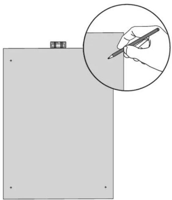
natural_image
Illustration of a hand holding a pencil inside a rectangular frame, with an inset showing the same object (no text or symbols present)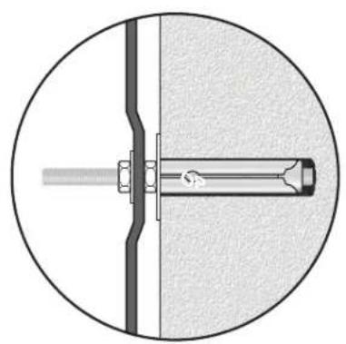
natural_image
Cross-sectional diagram of a mechanical assembly with a central shaft and mounting bracket (no text or labels)4.2 COLLEGAMENTI

IMPORTANTE
Sorgente BGM (BackGroundMusic)
Sorgente PA (Public Address)
Energy save (enabled/disabled)
Emergency password (enabled/disabled)
flowchart
graph TD
    A["Microphone units"] --> B["Escape"]
    C["Emergency units"] --> D["Broadcast units"]
    E["Currently model is emergency units"]
flowchart
graph TD
    A["Microphone units"] --> B["Emergency units"]
    A --> C["Broadcast units"]
    D["Escape"] --> E["Current model is emergency units"]
flowchart
graph TD
    A["Escape"] --> B["Edit Key"]
    C["Change"] --> D["Unit 1 --> 12 key unit"]
    E["Change"] --> F["Unit 2 --> 1 key unit"]
    G["→"] --> H["-->"]
12 key unit = base 12 zone (FMD 2012)
D4) >> Local microphone
Battery charger report
Battery voltage
26.9 V
Battery current
832 mA
Battery charge
90%
Supply voltage
29 V
Ambient temperature
30 C°
Battery impedance
42 mOhm
Escape
Test
Zone impedance report
Zone 1: out of range
Zone 2: out of range
Escape
(Ref. = out of range)
(Ref. = out of range)
report> EVENT LOG Storico eventi
report> EVENT LOG
flowchart
graph TD
    A["Event log menu"] --> B{Escape}
    B --> C["Number of fault events: 104"]
    B --> D["Fault log view"]
    D --> E{Number of alarm events: 0}
    E --> F["Alarm log view"]
    F --> G["Fault log view"]
    G --> H["1 - 01-Jan-12 00:00,06 - Fault on Link 20KHz"]
    G --> I["2 - 01-Jan-12 00:00,05 - Fault on S card Error"]
    G --> J["3 - 01-Jan-12 00:00,02 - Fault on Link 0"]
    G --> K["4 - 01-Jan-12 00:00,01 - Fault on Mic"]
    G --> L["5 - 01-Jan-12 00:00,00 - Rack on"]
    G --> M["6 - 27-Jun-16 14:44,44 - Fault on Unit 1 Serial"]
    G --> N["7 - 27-Jun-16 14:44,44 - Fault on Mic"]
    G --> O["8 - 27-Jun-16 14:44,40 - Rack on"]
    H --> P["Up"]
    H --> Q["Dn"]
Input 2 (not used): not active
Input 3 (not used): not active
Input 4 (not used): not active
Escape
Press dot for touch calibration test
Press emergency to test beep
Press reset key to exit
flowchart
graph TD
    A["set> IMP. REFERENCE"] --> B["Zone impedance settings"]
    B --> C["Set impedance reference"]
    C --> D["Set impedance tolerance"]
    D --> E["Save"]
    E --> F["Saved configuration"]
    G["Zone impedance reference"] --> H["Zone 1 reference: out of range"]
    G --> I["Zone 2 reference: out of range"]
    J["Impedance tolerance set"] --> K["Zone 1: 30% Change"]
    J --> L["Zone 2: 30% Change"]
bar
set> ALARM LEVELS | Alarm source levels | Alarm source levels (dB) | | :--- | :--- | | Emergency unit | -3dB | | Local microphone | -3dB | | Evac | -3dB | | Alert | -3dB |8.7 EMERGENZA MANUALE
DI SEGUITO VERRÀ DESCRITTA LA PROCEDURA PER LA GESTIONE DELLE EMERGENZE CON INTERVENTO MANUALE DA PARTE DI UN OPERATORE AUTORIZZATO.
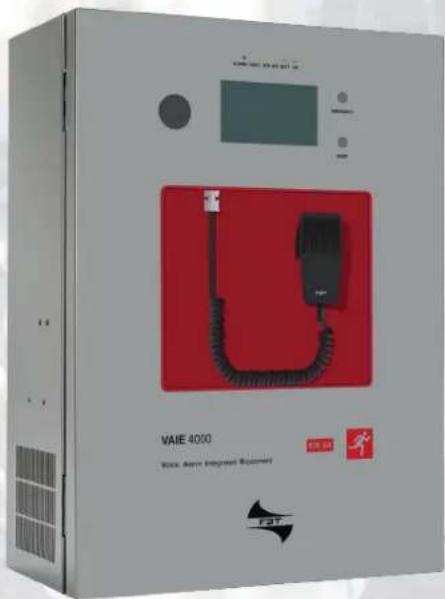
Compact wall-mount evacuation systems
Models:
VAIE 4101
VAIE 4102
VAIE 4251
VAIE 4252
User manual
Version 1.2
CODE: 44624
Cert. EN 54-16: 2008
No. 0068/CPR/163-2021
WARRANTY
This product is warranted to be free from defects in raw materials and assembly. The warranty period is governed by the applicable provisions of law. FBT will repair the product covered by this warranty free of charge if it is faulty, provided the defect has occurred during normal use. The warranty does not cover products that are improperly used or installed, mechanically damaged or damaged by liquids or the weather. If the product is found to be faulty, it must be sent to FBT free of charges for shipment and return. This warranty does not include any others, either explicit or implicit, and does not cover consequential damage to property or personal injury. For further information concerning the warranty contact your local FBT distributor.
Important! Before using the equipment, make yourself aware of all characteristics by reading carefully the instructions included in the printed manual or on the CD, paying particular attention to the safety notes.
MODEL:
SERIAL NUMBER:
PURCHASE DATE:
All FBT equipment is manufactured in accordance with the most stringent international safety standards and in compliance with European Community requisites. In order to use the equipment correctly and effectively, it is important to be aware of all its characteristics by reading these instructions and in particular the safety notes carefully.
TABLE OF CONTENTS
1. WARNINGS 48
1.1 Power supply and earthing 48
1.2 Safety notes 48
1.3 Maintenance 48
2. INTRODUCTION
2.1 Overview of the system 49
2.2 Functional features 49
2.3 Typical configuration 49
3. GENERAL DESCRIPTION
3.1 Front panel 50
3.2 Inside view 51
4. INSTALLATION AND CONNECTIONS
4.1 Wall mounting
4.2 Connections
4.2.1 Connection of auxiliary/music input
4.2.2 Connection of microphone units
4.2.3 Connection of relay outputs
4.2.4 Connection of input contacts
4.2.5 Connection of loudspeaker lines
4.2.6 Connection of the standby amplifier
4.2.7 Connection of the extension card
4.2.8 Connection of power supplies
5. OPERATIONAL CONDITIONS AND TERMINOLOGY
5.1 Signalling of operating conditions
6. DEFINITIONS
7. MENU STRUCTURE
8. USING THE SYSTEM
8.1 Configuration of the system 61
8.2 < MUSIC & PAGING > Menu 64
8.3
9. FAILURE STATUS
9.1 System operation and signalling in a generic failure condition 84
9.2 System operation and signalling with a fault on a loudspeaker line 84
10. TECHNICAL SPECIFICATIONS
85
1. WARNINGS
1.1 POWER SUPPLY AND EARTHING
These items of equipment are intended to work on a 230 VAC +10% / -15%, 50/60 Hz mains voltage and a 24 VDC supply from the internal batteries.
! N.B. – FEATURES OF THE WIRING SYSTEM
The mains AC power MUST be supplied through a two-pole differential thermal-magnetic circuit breaker with a current of 10 to 16A dedicated SOLELY to the equipment.
! N.B.
These devices have been designed to be connected to an earthed power supply.
Make sure that the equipment is always connected to earth in accordance with legal regulations.
1.2 SAFETY NOTES
All FBT equipment is made according to the strictest international standards and complies with European Union requisites. For correct and effective use of the equipment it is important to be aware of all the characteristics by reading carefully these instructions and warnings. While the equipment is in use, it is necessary to ensure adequate ventilation, above all leaving the slits for providing air for the cooling fans free.
REFER TO THE 'INSTALLATION AND CONNECTIONS' SECTION FOR THE RELEVANT PROCEDURES, TO BE CARRIED OUT BY TRAINED SPECIALISED PERSONNEL ONLY.
1.3 MAINTENANCE
It is highly recommended the user interface of the equipment to be checked every six months. To do this, use the test> FRONT PANEL function as shown on p. 26.

Important information for correct disposal of the product in accordance with EC Directive 2002/96/EC his product must not be disposed of as urban waste at the end of its working life. It must be taken to a special waste collection centre licensed by the local authorities or to a dealer providing this service. Separate disposal of electric and/or electronic equipment (WEEE) will avoid possible negative consequences for the environment and for health resulting from inappropriate disposal, and will enable the constituent materials to be recovered, with significant savings in energy and resources. As a reminder of the need to dispose of this equipment separately, the product is
marked with a crossed-out wheeled dustbin.

This product is in keeping with the relevant European Community Directives.
2. INTRODUCTION
2.1 OVERVIEW OF THE SYSTEM
The new VAIE 4000 range of integrated voice evacuation systems for emergency facilities, has been specifically designed for wall-mounting and equipped with control units, certified in compliance with EN 54-16:2008 / EN 54-4 standards.
These models are capable of managing 1 or 2 alarm zones - with an overall power of 100 or 250 W - driven by a single amplifier, as well as remote microphone stations and controlled inputs to be connected to a central fire-fighting system.
2.2 FUNCTIONAL FEATURES
• Rated audio output: 100 W / 250 W.
- Backlit 4.3" display with touch screen for selecting the alert and evacuation zones and enabling navigation for adjusting volume levels, configuring the equipment and viewing failures.
- Handheld fireman's paging microphone.
- Sending out of pre-recorded EVACUATION and ALERT messages.
- 4 off controlled input contacts, configurable for playing the evacuation and/or alert messages to the zone, for resetting the messages or for signalling the failure of an external equipment.
- 1 off auxiliary/music input configurable as a music source, a call with precedence activation or a call with automatic activation (VOX).
• 2 off configurable relay outputs.
- Local button for placing the system in an emergency state, equipped with its own LED.
- Local button for resetting the fault acoustic signal and stopping playing out of alarm messages.
- EN54-4 certified internal battery charger unit for 24Vdc secondary power supply.
- Possibility to connect up to 4 MBT 1000 broadcasting microphone units or - as an alternative - up to 2 Series FMD 2000 remote emergency units.
- Possibility to set a standby amplifier (for VAIE 4102 and VAIE 4252 models only).
- An optional extension card can be used for broadcast general calls towards other connected units or as an additional music input.
2.3 TYPICAL CONFIGURATION
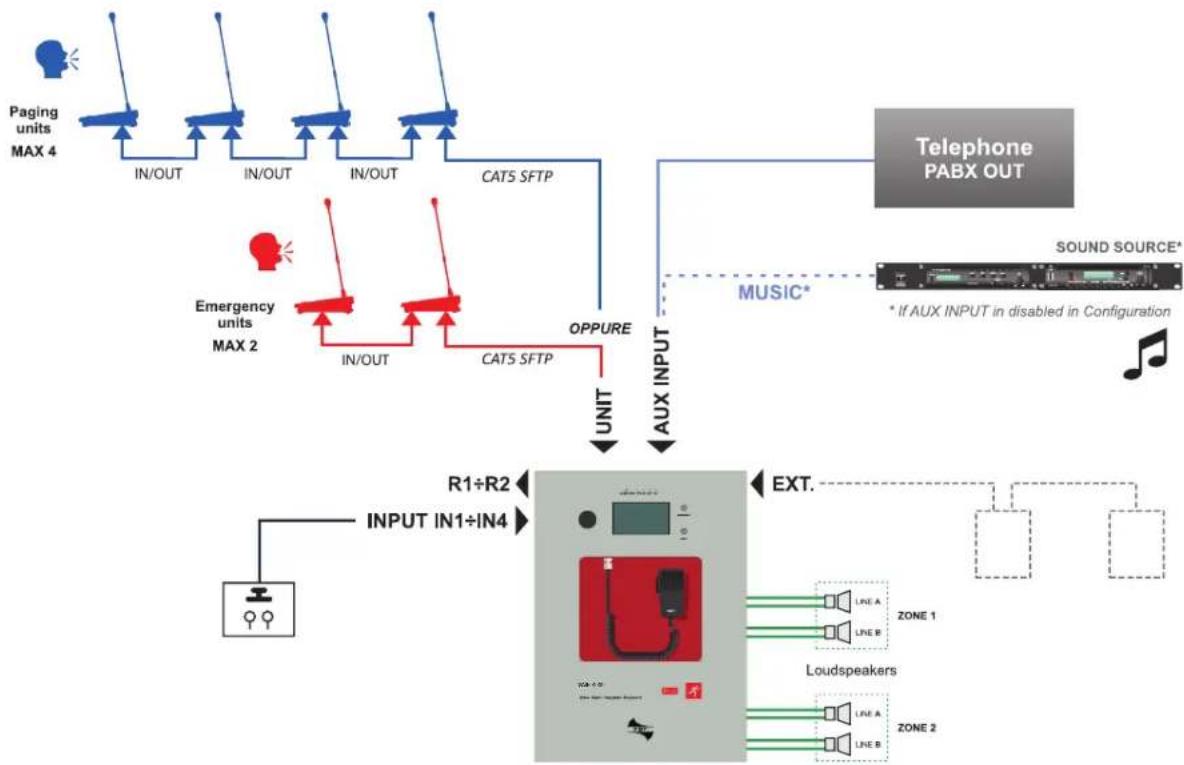
flowchart
graph TD
    A["Paging units MAX 4"] --> B["IN/OUT"]
    B --> C["IN/OUT"]
    C --> D["IN/OUT"]
    D --> E["CATS SFTP"]
    E --> F["AUX INPUT"]
    F --> G["SOUND SOURCE*"]
    G --> H["Telephone PABX OUT"]
    I["Emergency units MAX 2"] --> J["IN/OUT"]
    J --> K["CATS SFTP"]
    K --> L["OPPURE"]
    L --> M["UNIT"]
    M --> N["R1÷R2 INPUT IN1÷IN4"]
    N --> O["Loudspeakers"]
    O --> P["EXT."]
    P --> Q["LINE A ZONE 1"]
    O --> R["LINE B ZONE 2"]
    style A fill:#f9f,stroke:#333
    style B fill:#bbf,stroke:#333
    style C fill:#bbf,stroke:#333
    style D fill:#bbf,stroke:#333
    style E fill:#bfb,stroke:#333
    style F fill:#ffb,stroke:#333
    style G fill:#cfc,stroke:#333
    style H fill:#fcc,stroke:#333
    style I fill:#fff,stroke:#333
    style J fill:#fff,stroke:#333
    style K fill:#fff,stroke:#333
    style L fill:#fff,stroke:#333
    style M fill:#fff,stroke:#333
    style N fill:#ccf,stroke:#333
    style O fill:#ccf,stroke:#333
    style P fill:#cfc,stroke:#333
    style Q fill:#fcc,stroke:#333
3. GENERAL DESCRIPTION
3.1 FRONT PANEL
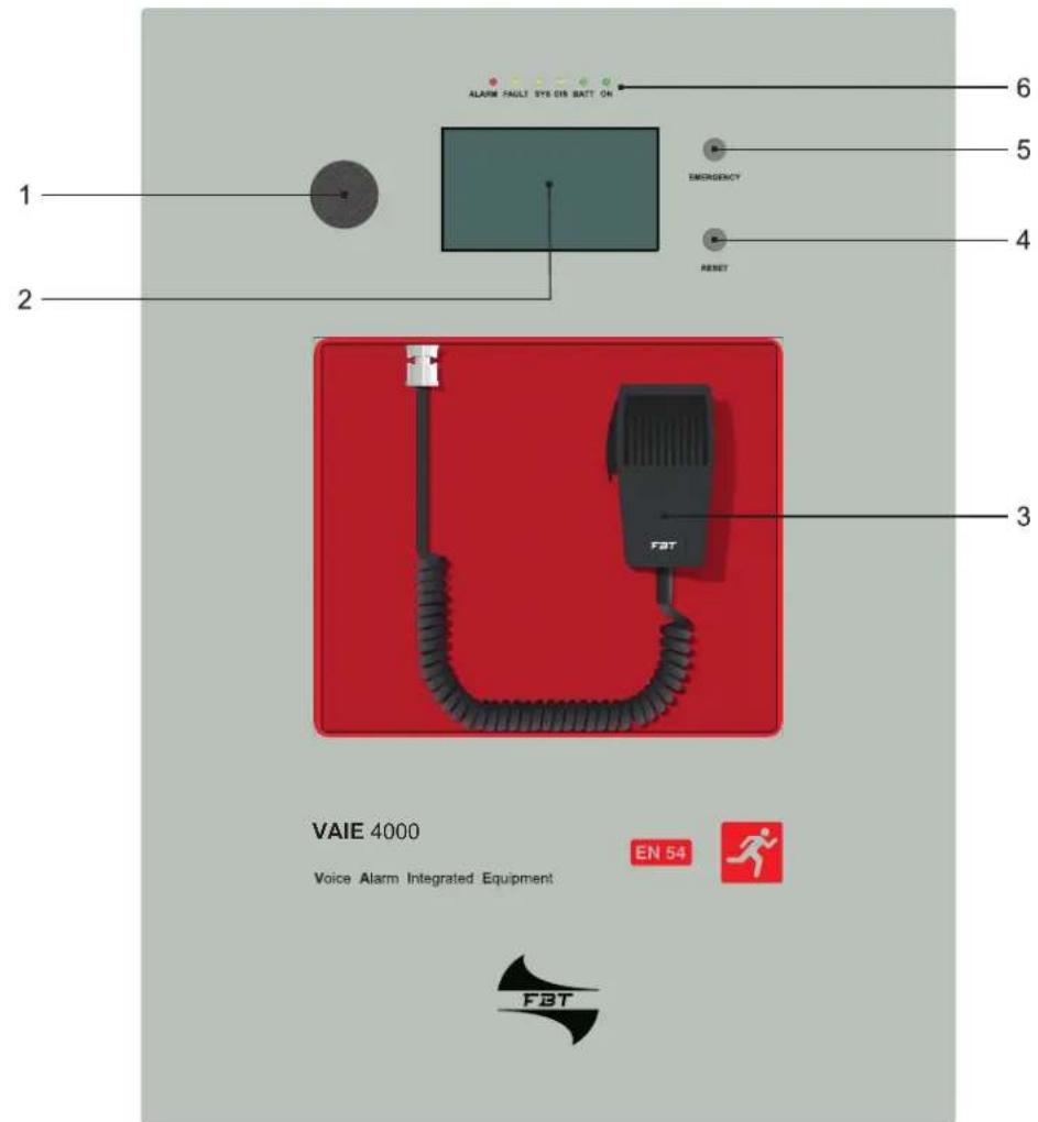
1) Integrated loudspeaker for playing back the output signals from the zones or the signals of the input sources and for replaying the acoustic signal indicating that a failure has been detected (beep). The signalling tone will be automatically muted if the conditions of failure end. Furthermore, in accordance with the regulations, the beep is muted by the system while the Emergency Microphone is being used.
2) Backlit 4.3" display with touchscreen for selecting the Alert/Evacuation zones and for navigation for adjusting volume levels, configuring the equipment and viewing failures.
3) Handheld fireman's paging microphone.
4) RESET button.
5) EMERGENCY button.
6) Status LEDs:
• ALARM (red) Ongoing alarm.
- FAULT (yellow) Fault detected in the system.
- SYS (yellow) Fault of one of the internal processors (DSP / CPU).
• DIS (yellow) Disablement status of some emergency functions status (e.g.: during the SD maintenance).
• BATT (green) Internal batteries power supply.
• ON (green) @230 VAC Mains power supply.
3.2 INTERNAL VIEW
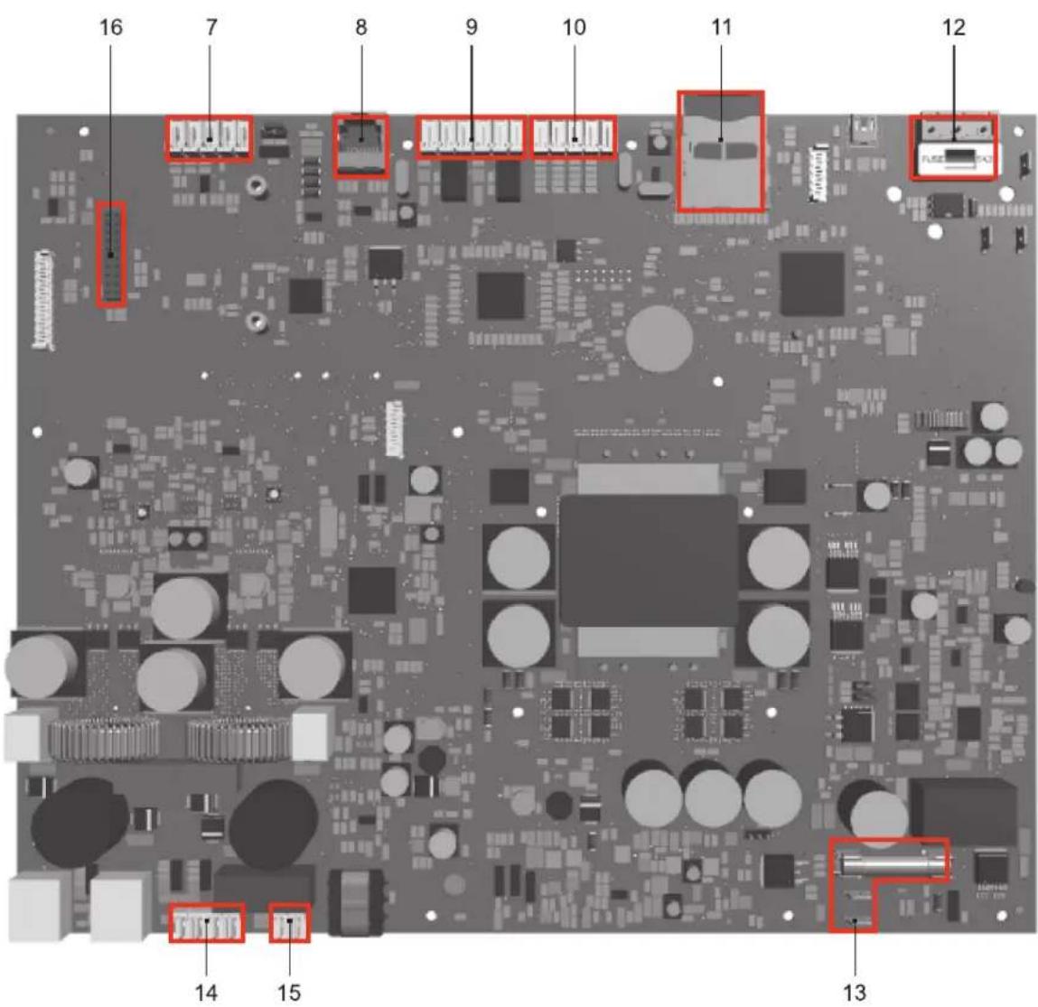
7) Input terminal strip for auxiliary sources with precedence contact. If not used for auxiliary sources, this input can be used for a music source connection (see point set> PAGING CALLS, page 22).
8) Input for microphone units (4 paging units PMB106-G or, as an alternative, 2 emergency units FMD 2000).
9) 2 off relay output contacts (R1, R2).
10) 4 off controlled input contacts (IN1÷IN4).
11) SD card.
12) Connection to 230 VAC power supply. (with T2A, fuse).
13) Connection to 24 Vdc battery power (with T10A fuse).
14) Connection of loudspeakers lines.
15) Connection of standby amplifier.
16) Connection for extension card.
4. INSTALLATION AND CONNECTIONS

N.B.
Please remind that the operations illustrated in this part of the manual must be carried out by specialised personnel ONLY, trained and qualified in the equipment installation and maintenance. When the VAIE is opened, parts entailing a high risk of electric shocks become accessible.
It is advisable to install the equipment in a closed and sheltered place, protected against possible sources of damage (rain, moisture, high temperatures, etc.).
Depending on requirements, the cables can be inserted by eliminating either the plugs sealing the holes in the top or the rear door (in both cases use a flat screwdriver or a cutter to lift them and remove them).

It is important to keep the power cables separate from those dedicated to the other connections.
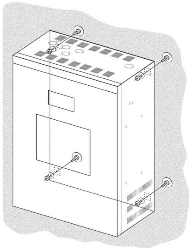
4.1 WALL MOUNTING
Take the cardboard template included in the package and position it at a suitable height so that it is accessible to the user. Ideally, the front display should be at eye level.
Having decided on the position, mark the four points on the wall and fit Fischer wall plugs (min. ∅ 9 mm) equipped with bolts into them.
Using the wall plugs as reference pins, lift the equipment and hook it to the wall. It is advisable for this activity to be carried out by two people.
Tighten the bolts.
natural_image
Technical line drawing of an electrical cabinet with mounting holes and internal compartments (no text or symbols)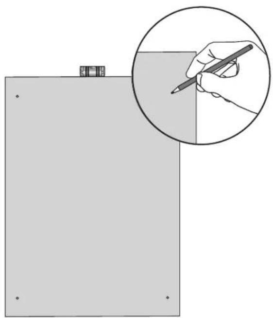
natural_image
Illustration of a hand holding a pencil inside a rectangular frame, with an inset showing the same hand (no text or symbols present)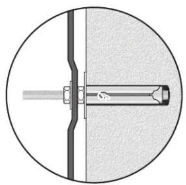
natural_image
Cross-sectional diagram of a mechanical assembly with a central shaft and bolted joint (no text or labels)4.2 CONNECTIONS
! N.B.
Check that the main thermal-magnetic circuit breaker is switched OFF. If it is not, switch it OFF before carrying out any other activities in the cabinet as there is a danger of electric shocks.
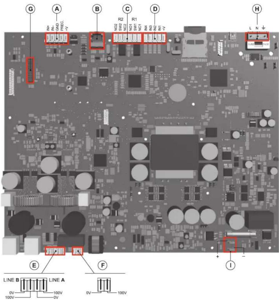
Proceed with connection of the various devices, referring to the appropriate points of the manual:
A) Point 4.2.1 Connection of auxiliary/music input (page 10)
B) Point 4.2.2 Connection of microphone units (page 11)
C) Point 4.2.3 Connection of relay outputs (page 11)
D) Point 4.2.4 Connection of input contacts (page 11)
E) Point 4.2.5 Connection of the loudspeakers lines (page 12)
F) Point 4.2.6 Connection of the standby amplifier (page 12)
G) Point 4.2.7 Connection of the extension card (page 13)
Once the basic connections have been made, it is possible to go on to connect the power supplies: H/I) Point 4.2.8 Connection of power supplies (page 13)
N.B.: It is essential to follow the correct sequence for powering up the equipment, failing which it could be damaged.
4.2.1 CONNECTION OF AUXILIARY/MUSIC INPUT
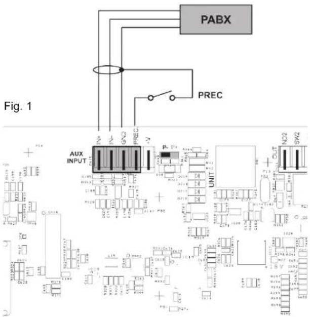
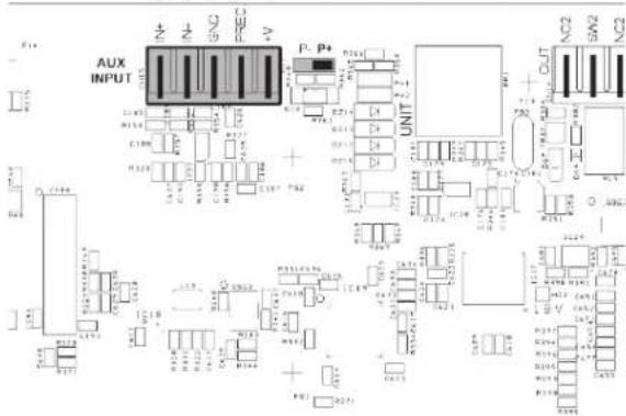
The AUX INPUT terminals (7) are available for connecting auxiliary sources (e.g. a PABX or a base for announcements with a precedence contact). In the first case, it is necessary to fit a jumper in position "P-" (see Fig. 1). In the second case, on the other hand, using a pre-amplified station of the MBT 1101 range, connection between the AUDIO OUT socket of the base
and the AUX terminals has to be made as indicated in the table and the jumper will have to be positioned on "P+" (see (Fig. 2).
NOTE: Selection between modes P- and P+ must be made also via the menu (AUDIO SETTING > set>PAGING CALLS, page 22).
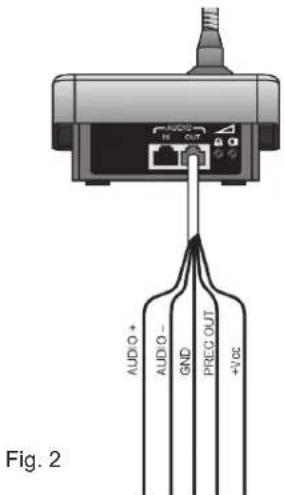
| Pin | Unit AUDIO OUT | VAIE AUX INPUT |
| 1 Audio + IN + | ||
| 2 Audio - IN - | ||
| 3 GND GND | ||
| 4 Precedence OUT PREC | ||
| 5 Not connected | ||
| 6 Vdc +V | ||
| 7 Serial + | ||
| 8 Serial - | ||
| Shield GND GND |
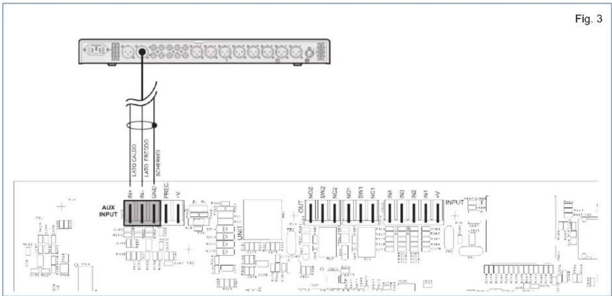
In case the AUX function has not been activated, it is possible to use these terminals to connect a music source (Fig. 3).
4.2.2 CONNECTION OF MICROPHONE UNITS
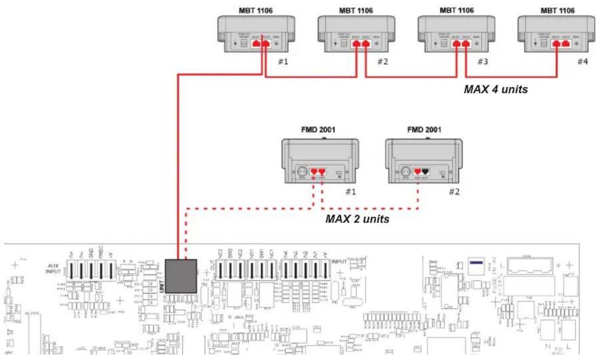
Use a CAT. 5e SF/UTP cable for connecting the UNIT socket (8) to the 'IN/OUT' sockets of the MBT 1106 paging units (up to 4). As an alternative, it is possible to connect up to 2 FMD 2000 range emergency units.
flowchart
graph TD
    A["MBT 1106"] -->|#1| B["MAX 4 units"]
    C["FMD 2001"] -->|#1| D["MAX 2 units"]
    E["FMD 2001"] -->|#2| D
    B --> F["UNIT"]
    D --> F
    style A fill:#f9f,stroke:#333
    style C fill:#f9f,stroke:#333
    style E fill:#f9f,stroke:#333
    style B fill:#ccf,stroke:#333
    style D fill:#ccf,stroke:#333
    style F fill:#cff,stroke:#333
4.2.3 CONNECTION OF RELAY OUTPUTS
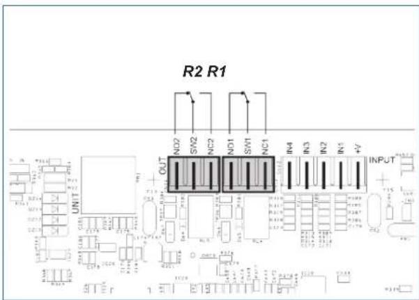
Two relay outputs are available on terminals R1 and R2 (9) for signalling towards outside peripheral units.
For each relay, an exchange state contact (SW), a normally open contact (NO) and a normally closed (NC) contact are available.
4.2.4 CONNECTION OF INPUT CONTACTS
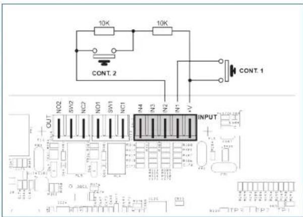
There are 4 input contacts on the INPUT terminal strip (10): the figure shows an example of a connection in which contact 2 is of the monitored type while contacts 1 is not.
In order for the control function of the connection line to the fire-control central unit to be used, the resistors must be placed close to the contacts of the fire-control central unit.
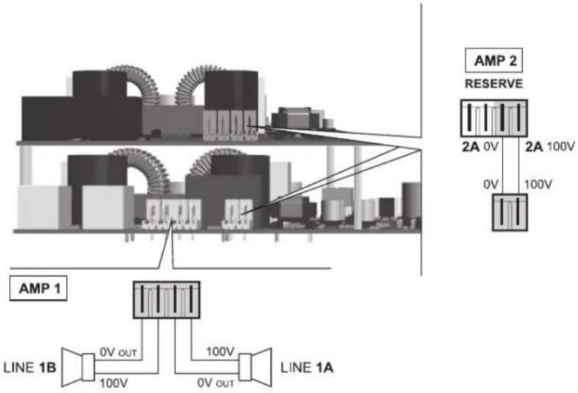
4.2.5 CONNECTION OF LOUDSPEAKER LINES Terminals (14) are dedicated terminals for connection of the loudspeaker lines.
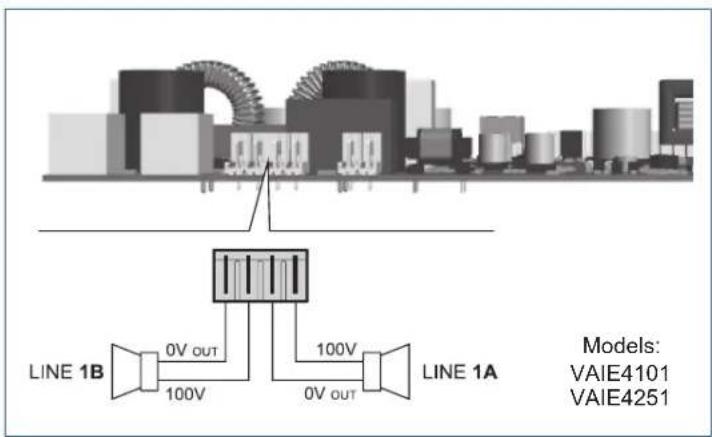
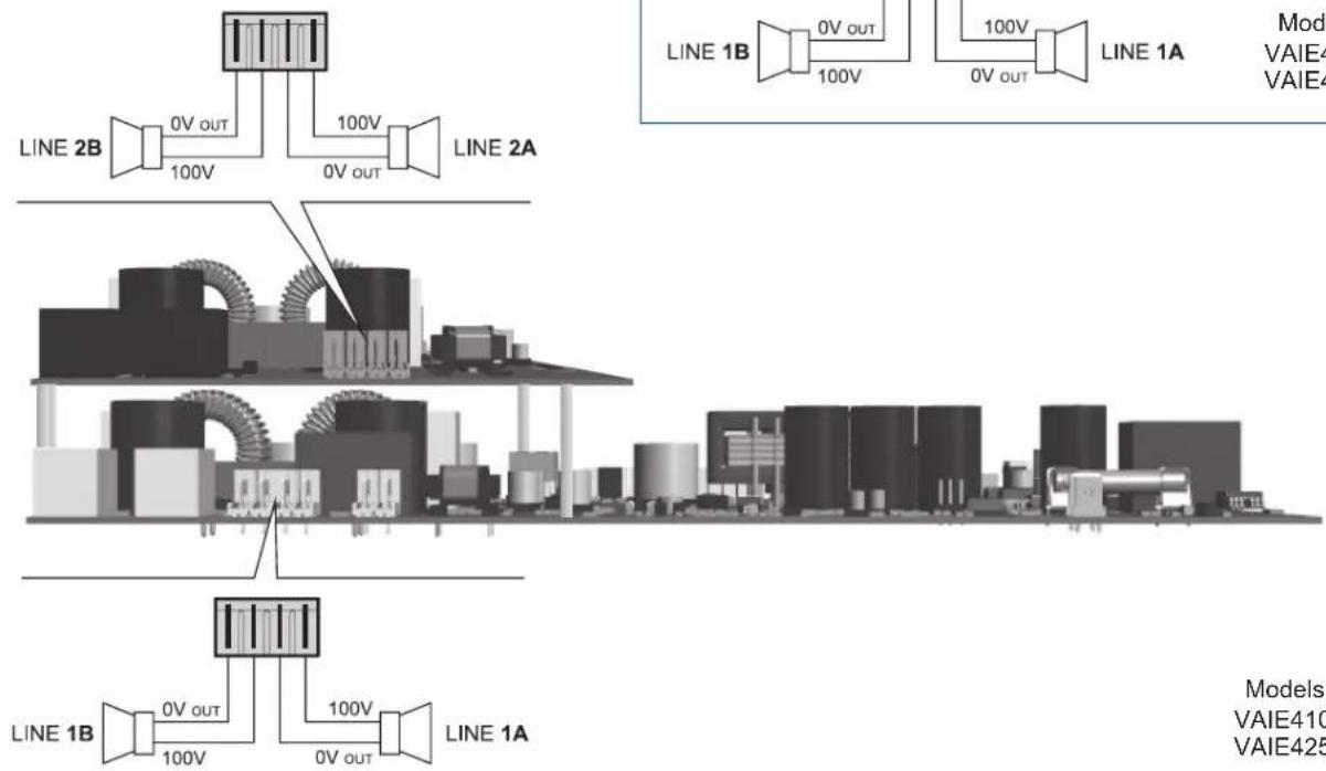
N.B.: Please refer to the local regulations of the country where the product is installed for the type and sizing of the connection cables.
The figures show the connection for the single-aplifier models (VAIE4101 and VAIE4251) and double-amplifier models (VAIE4102 and VAIE4252).
Models:
VAIE4102
VAIE4252
4.2.6 CONNECTION OF THE STANDBY AMPLIFIER
Terminals (15) are dedicated terminals for connection of the standby amplifier (VAIE4102 and VAIE4252 models only).
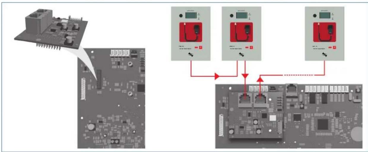
4.2.7 CONNECTION OF THE EXTENSION CARD
The connector (16) is dedicated to connecting the extension card; via this connection broadcast calls rom one VAIE to all the others are allowed (general call). Other VAIE4000 units (up to 32) can be connected to the RJ45 sockets of the board.
flowchart
graph TD
    A["Microcontroller"] --> B["Internet Port 1"]
    A --> C["Internet Port 2"]
    A --> D["Internet Port 3"]
4.2.8 CONNECTION OF POWER SUPPLIES
! N.B.
Check that the main thermal-magnetic circuit breaker is switched OFF. If it is not, switch it OFF before carrying out any other activities in the cabinet as there is a danger of electric shocks.
! N.B.
These devices have been designed to be connected to an earthed power supply.
Make sure that the equipment is always connected to earth in accordance with legal regulations.
It is essential to follow the correct sequence for powering up the equipment, failing which it could be damaged.
The batteries must be placed on the bottom of the device, ensuring their stationariness.
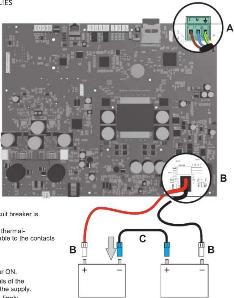
1> Check that the main thermal-magnetic circuit breaker is switched OFF.
2> Connect the power cable coming from the thermal-magnetic circuit breaker and the earth cable to the contacts on the terminal strip (A) - see figure.
3> Connect the external terminals (B) of the batteries, observing the correct polarities.
4> Switch the thermal-magnetic circuit breaker ON.
5> Make a jumper between the inside terminals of the batteries using the cable (C) included in the supply.
6> Close the front door, tightening the screws firmly.
5. OPERATIONAL CONDITIONS AND TERMINOLOGY
Following is a list of how the operating conditions of the system are signalled and of the definitions used on the subsequent pages of the manual, completed by indications of a general nature.
5.1 SIGNALLING OF OPERATING CONDITIONS
The VAIE is designed to signal the different operating conditions as defined below:
Idle state (ALARM, FAULT and SYS LEDs off)
Normal operating condition, with no current faults or emergencies.
Alarm Status (ALARM red LED on)
Operating condition signalling the presence of at least one alarm signal, either pre-recorded or live, on the output zone.
Faulty status (FAULT yellow LED on)
Operating condition signalling the presence of at least one fault detected by the internal diagnostic system, with the relevant LED turning on.
System failure (SYS yellow LED on)
Operating condition signalling that the system has crashed due to temporary or permanent CPU malfunctioning, detected by the watchdog device.
Disable status (DIS yellow LED on)
Operating condition signalling the disablement of an emergency function, such as playing of pre-recorded messages during the maintenance phase of the SD card.
Automatic Emergency (Display showing 'AUTOMATIC EMERGENCY' with active zone)
Sequence of operations performed by an external peripheral (tipically the fire-control unit) connected to the control inputs that, depending on how these are programmed, activates the Alarm Status or resets the alarms.
Manual Emergency (LED of the EMERGENCY button steady ON or flashing)
Procedure of action on the system manual controls by an authorised operator, in order to activate emergency sources. Operations in the Manual Emergency mode have priority over those activated in the Automatic Emergency mode.
6. DEFINITIONS
BGM source (Background Music)
Audio source for background music.
PA source (Public Address)
One of the audio sources that can occupy the zone/s for service announcements.
Emergency Source
One of the audio sources that can occupy the zone/s for voice emergency announcements (pre-recorded messages announcing an Alert and/or Evacuation, live messages from the local microphone, a call from a remote emergency microphone station). Activation of an Emergency Source generates the operational condition of "State of Alarm".
Priority
Occupation of the output zone/s by an audio signal or a reset order is governed hierarchically by the priority level assigned to each active source. The current activation of the zone can be stopped only by another with a higher priority.
NOTA
The menu shown in this manual refers to a device with 2 zones (VAIE4102 and VAIE4252) and the extension card inserted and activated. If the extension card is not used, the menu will show no references about it. In the case of the VAIE4101 and VAIE4251 models, no references to zone 2 will appear in the menu.
7. MENU STRUCTURE
The VAIE allows system functions to be accessed through a series of Management Panels grouped, according to their operational typology and intended use, in Menus lists accessible from the MAIN MENU window. Furthermore, to the following Menus lists have been assigned different levels of access, with reference to the various circumstances requiring different degrees of skill and authorisation of the personnel assigned. In each menu it is possible to browse through the options listed by running a finger over the sidebar or pressing the 'Up' and 'Dn' (Down) buttons. To select an item, press the appropriate button. Similarly, the levels can be adjusted simply by moving the cursor along the indicator bar.
MENU | BASE LEVEL
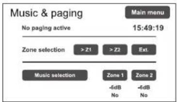
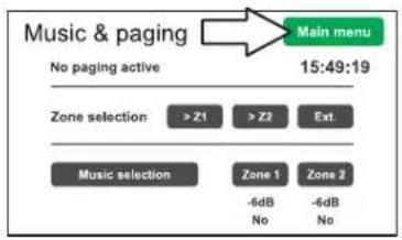
Default window for using the system in its normal Idle conditions; it allows the BGM (Background Music) sources control and volume adjustment. This menu remains inaccessible in a State of Alarm.
At this basic level, the RESET button is not operational.
This panel is shown immediately when the system is switched ON.
To access the Main Menu press the 'Main Menu' button.
For the specific features of the MUSIC & PAGING menu, see page 20.
MENU | BASE LEVEL
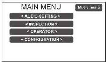
Main menu for selecting the four VAIE operational levels.
At this basic level the RESET button is not operational.
To go back to the MUSIC Menu press the 'Music Menu' button.
To select the required item press the relevant key.
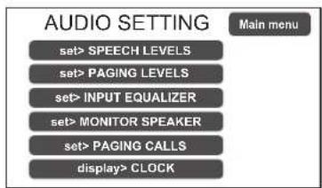
From the MAIN MENU screen, press the
To select the required item press the relevant key.
To return to the main screen press 'Escape'
For the specific features of the AUDIO SETTING menu, see page 21.
First level of access, for inspecting the state of the system.
This is intended for the personnel responsible for initial checking of the causes of a fault or emergency. At this level the function of the RESET button is that of muting the acoustic signal indicating the FAULT.
To select the required item press the relevant key.
To go back to the main menu Press 'Main menu'.
For the specific features of the menu INSPECTION, see page 24.
Second level of access, for instructed personnel authorised to manage the system in emergency, failure and disabled conditions.
The relevant login password must be entered to access this menu.
To go back to the main screen press 'Main menu'.
For the specific features of the OPERATOR menu, see page 27.
Third level of access, for instructed personnel authorised to work on the advanced functions of the system and to alter the configuration parameters, for starting up and altering the system. The relevant login password must be entered to access this menu.
To go back to the main screen press 'Main menu'.
For the specific features of the CONFIGURATION menu, see page 30.
Fourth level of access, included among the options of the CONFIGURATION menu, for technical assistance, firmware up-dating and altering the VAIE system operating parameters. Use is permitted only to personnel of the technical service who have the necessary login password.
To go back to the main screen press 'Main menu'.
NOTE: Once the operation within the password protected menus is done, please take care to restore the access level protection logging out by pressing the Exit> Logout button.
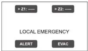
Operational environment for managing Manual Emergencies with top priority. Accessible at all times with the dedicated "EMERGENCY" key, it can be used by authorised personnel only, suitably instructed with regard to the Emergency and Evacuation Plan (PEE).
For the specific features of the EMERGENCY menu, see page 37.
8. USING THE SYSTEM
After making all the connections, observing the indications provided in the relevant chapter, and once the door of the cabinet has been closed, the display lights up and shows the panel of the MUSIC Menu, from which it is possible, by pressing the 'Main Menu' key, to access the main screen for selecting the menus.
If the system is being used for the first time, or if changes have been made to its configuration, proceed as indicated in the CONFIGURATION OF THE SYSTEM section. If, on the other hand, the initialisation procedure has already been completed, continue with the indications for use as provided below.
- For normal use for broadcasting music and microphone announcements, users may limit their activities to the MUSIC & PAGING and AUDIO SETTING menus.
- For management in faulty/emergency conditions and for configuration using advanced functions, see the INSPECTION, OPERATOR and CONFIGURATION menus below.
- For sending emergency messages, see the MANUAL EMERGENCY section.
Configuration activities may be carried out only by qualified personnel, suitably trained for this purpose.
A) Password
rom the MUSIC MENU, go to the MAIN MENU and select < CONFIGURATION >. If access only with a password is enabled, 'Enter configuration password' will appear on the screen.
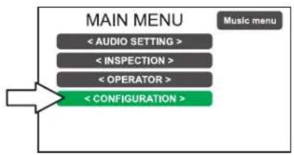
flowchart
graph TD
    A["MAIN MENU"] --> B["< AUDIO SETTING >"]
    A --> C["< INSPECTION >"]
    A --> D["< OPERATOR >"]
    A --> E["< CONFIGURATION >"]
    F["Music menu"] --> A
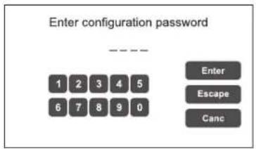
Enter the 4-digit code of the password and confirm by pressing 'Enter' (the factory default password is 3333; see page 30).
B) Muting the BEEP
During the initialisation process, it is possible that faults may be detected due to differences between the configuration of the system being connected and the values set by default. To mute the acoustic signal (beep) temporarily, browse down through the CONFIGURATION menu and select the item 'Beep operation'.
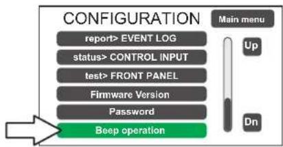
flowchart
graph TD
    A["REPORT> EVENT LOG"] --> B["status> CONTROL INPUT"]
    B --> C["test> FRONT PANEL"]
    C --> D["Firmware Version"]
    D --> E["Password"]
    E --> F["Beep operation"]
    G["Main menu"] --> H["Up"]
    G --> I["Dn"]
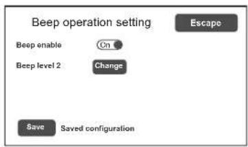
In the 'Beep operation setting' window, move the 'Beep enable' cursor to 'Off'.
Press 'Save' to save this setting.
! N.B.
In order to comply with regulations, before returning the equipment to its normal operation it is necessary to enable the acoustic signalling by returning the 'Beep enable' slider to its 'On' position.
C) Acquisition of impedances
From the CONFIGURATION menu, select the item 'set>IMP. REFERENCE' to access the 'Zone impedance setting' screen page.
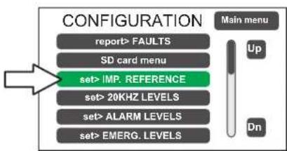
flowchart
graph TD
    A["REPORT> FAULTS"] --> B["SD card menu"]
    B --> C["set> IMP. REFERENCE"]
    C --> D["set> 20KHZ LEVELS"]
    C --> E["set> ALARM LEVELS"]
    C --> F["set> EMERG. LEVELS"]
    G["Main menu"] --> H["Up"]
    G --> I["Dn"]
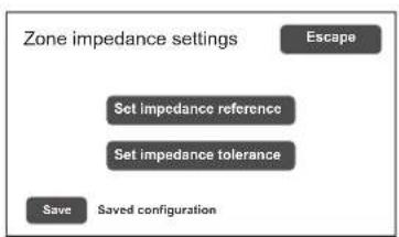
flowchart
graph TD
    A["Zone impedance settings"] --> B["Escape"]
    B --> C["Set impedance reference"]
    C --> D["Set impedance tolerance"]
    D --> E["Save"]
    E --> F["Saved configuration"]
From here it is possible to set the reference impedance and the tolerance for controlling the impedance of the loudspeaker lines (refer to the point on Acquisition of impedance and setting of tolerance on page 32).
In the CONFIGURATION menu, browse through the items and select 'set>RACK CONFIG'.
From here it is possible to configure all the basic settings of the system.
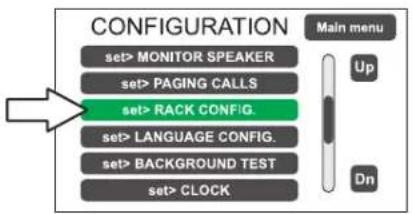
flowchart
graph TD
    A["set> MONITOR SPEAKER"] --> B["set> PAGING CALLS"]
    B --> C["set> RACK CONFIG."]
    C --> D["set> LANGUAGE CONFIG."]
    D --> E["set> BACKGROUND TEST"]
    E --> F["set> CLOCK"]
    G["Main menu"] --> H["Up"]
    G --> I["Dn"]
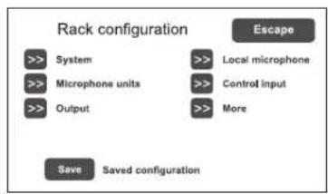
flowchart
graph TD
    A["Rack configuration"] --> B[">> System"]
    A --> C[">> Microphone units"]
    A --> D[">> Output"]
    A --> E[">> Local microphone"]
    A --> F[">> Control input"]
    A --> G[">> More"]
    H["Save"] --> I["Saved configuration"]
    J["Escape"] --> K["->"]
D1) >> System
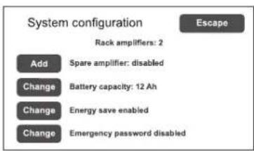
The item 'Rack amplifiers' automatically shows the number of amplifiers present in the system.
Spare amplifier: Press 'Change' to activet/deactivate the spare amplifier function (VAIE4102 and VAIE4252 models only).
Battery capacity: Press 'Change' to select a value: 12 or 18 Ah. Please see page 34 for details.
Energy save (enabled/disabled)
For enabling/disabling the function allowing the batteries to go into the energy saving mode in the absence of the mains power supply.
N.B. In order to comply with the regulations, the "Energy save" function should always be enabled.
Emergency password (enabled/disabled)
For enabling/disabling the password request for the activation of the Emergency status; the password is the same as for accessing the OPERATOR level. If the password is disabled, the EMERGENCY button must be pressed twice consecutively.
D2) >> Microphone units
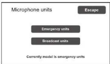
flowchart
graph TD
    A["Microphone units"] --> B["Escape"]
    C["Emergency units"] --> D["Broadcast units"]
    E["Currently model is emergency units"]
On the 'Microphone units' screen page, use the sub-menus to set the configuration of the microphone units connected to the 'UNITS' RJ45 socket of the VAIE. Select 'Emergency units' for FMD 2000 range models or 'Broadcast units' for MBT 1106 models.
Emergency units Configuration of the keys for FMD 2000 range emergency units
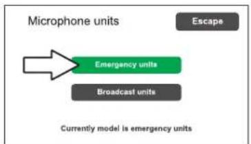
flowchart
graph TD
    A["Current model is emergency units"] --> B["Emergency units"]
    B --> C["Broadcast units"]
    C --> D["Escape"]
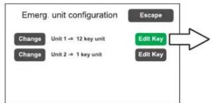
flowchart
graph TD
    A["Escape"] --> B["Edit Key"]
    B --> C["Edit Key"]
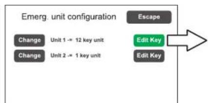
    D["Change"] --> E["Unit 1 -= 12 key unit"]
    F["Change"] --> G["Unit 2 -= 1 key unit"]
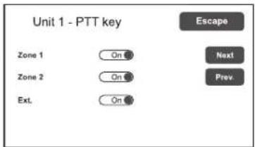
It is possible to connect up to two remote emergency units: click on 'Change' to set the unit type:
1 key unit = single zone unit (FMD 2001)
12 key unit = 12-zone unit (FMD 2012)
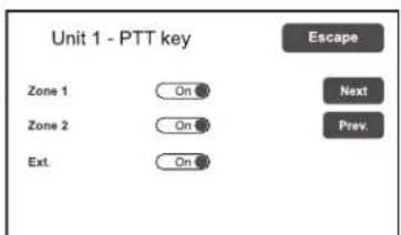
Then, press 'Edit Key' to configure each key (see Microphone units on page 34).
D3) >> Output
flowchart
graph TD
    A["On"] --> B["Fault EviC. Alert M"]
    B --> C["Logic"]
    C --> D["Positive (active high)"]
    D --> E["Of Off"]
    E --> F["Broad"]
    F --> G["Next"]
    G --> H["Prev."]
    I["Escape"] --> J["Off"]
    J --> K["O"]
    K --> L["ff"]
    L --> M["f"]
    M --> N["Of Off"]
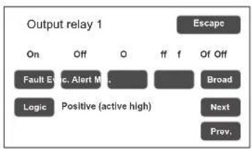
Screen page for setting the outputs (Output 1 / Output 2).
Use the 'Next' and 'Prev.' keys to move from one relay to the other. See Point Output, page 35.
D4) >> Local microphone
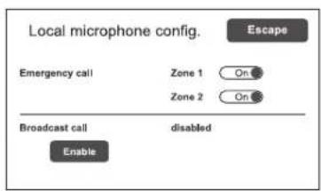
Screen page for setting the default for the broadcasting zone (recall of messages and hands-free calls in emergency conditions, enabling the local microphone to be used for broadcast calls).
See Point Local Microphone, page 35.
D5) >> Control input
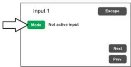
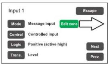
Screen page for managing the inputs being controlled (IN1 to IN4). Use the 'Next' and 'Prev.' keys to move from one input to another.
flowchart
graph TD
    A["Input 1"] --> B["Mode"]
    B --> C["Not active input"]
    C --> D["Escape"]
    C --> E["Next"]
    C --> F["Prev."]
flowchart
graph TD
    A["Mode"] --> B["Message input"]
    C["Control"] --> D["Controlled input"]
    E["Logic"] --> F["Positive (active high)"]
    G["Trans."] --> H["Level"]
    I["Escape"] --> J["Edit zone"]
    K["Next"] --> L["Prev."]
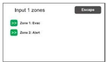
Mode Setting of the operating mode of the input (message, reset, external fault or de-activated) and of the relevant zones (only if the item "Message input" is selected).
Control Enabling/disabling of connection line test of the selected input.
Logic Setting of the logic for input activation.
Trans Enabling of the level or transition activation of the input (in case 'Message input' is selected).
E) Emergency messages
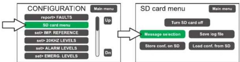
The default messages (Alert, Evacuation and Chime) are stored in the SD card mounted on the main board. To access the SD management, select the item CONFIGURATION > 'SD card menu'. See Point set> SD card menu at page 31 for the relevant operations.
flowchart
graph LR
    A["CONFIGURATION"] --> B["report> FAULTS"]
    A --> C["SD card menu"]
    C --> D["set> IMP. REFERENCE"]
    C --> E["set> 20KHZ LEVELS"]
    C --> F["set> ALARM LEVELS"]
    C --> G["set> EMERG. LEVELS"]
    H["Main menu"] --> I["Up"]
    H --> J["Dn"]
    K["SD card menu"] --> L["Message selection"]
    L --> M["Store conf. on SD"]
    L --> N["Save log file"]
    L --> O["Load conf. from SD"]
    P["Main menu"] --> Q["Turn SD card off"]
8.2 MUSIC & PAGING MENU
SETTING THE AUDIO PARAMETERS OF BGM SOURCES
| Screen page Description of main panel Description of options | ||
| This panel can be divided into three different functional areas:The upper area (A) shows the source that is currently engaging the equipment in a broadcast call.The central area (B) shows the available controls for broadcast calls coming from local microphone, if this function is enabled.In the lower area (C) it is possible to control the music source, if the AUX input is not used or if the optionale extension card is present. | SELECTION OF THE BGM SOURCEIf the AUX inputs is not already configured for other uses (Aux mode = AUX OFF) or the extension card input is not used for the connection to other cabinets, a music source can be connected and controlled.Press ‘Music selection’ to select the music input and then the zone key which you want to select the source.ADJUSTMENT OF THE INPUT MUSIC VOLUMEIt corresponds to the AUX input and ‘Ext in pahing’ volume level (see set> SPEECH LEVELS).ADJUSTMENT OF THE OUTPUT MUSIC VOLUMEPress the zone button: the ‘Zone X output level’ bar will appear on which you can adjust in a similar way to the general volume.The set attenuation value is visible directly on the display (from 0dB to -70dB / Off).The set value is stored and displayed below the relevant button.MUSIC ACTIVATION / DEACTIVATION FOR THE ZONE OUTPUTThe activation of the music on the zone is recognizable by the green color of the relevant button. Otherwise, the button will be blue.To change the activation status, press the zone key once and then press it again before the level bar disappears. | |
8.3
SETTING THE AUDIO PARAMETERS OF THE PA SOURCES
| Screen page Description of the main panel Description of options | ||
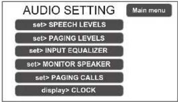 | Music and broadcast source control panel displayed by the VAIE in conditions of normal “Idle” state operation.Access menu to the panels for managing the parameters concerning the music and voice source audio.To select the desired item, press the relevant key.To return to the main screen, press ‘Escape’ | The options of the AUDIO SETTING menu enable access to the following panels:set> SPEECH LEVELSset> PAGING LEVELSset> INPUT EQUALIZERset> MONITOR SPEAKERset> PAGING CALLSdisplay> CLOCK |
| set> SPEECH LEVELS Management of the voice sources Relevant items | ||
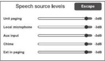 | On this screen page the volume of the voice sources connected to the VAIE can be adjusted.To change the value indicated, move the cursor along the bar next to each source.To return to the <AUDIO SETTING > screen, press ‘Escape’. | Unit pagingBroadcasting calls coming from microphone units connected to the VAIE.Local microphoneBroadcasting calls by local microphone.Aux inputBroadcasting calls by auxiliary input.ChimeWarning signal.Ext in pagingInput signal level of the extension card. |
| set> PAGING LEVELS Management of the output level | ||
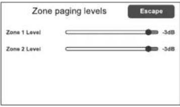 | On this screen page the zone output volume during broadcasting calls can be adjusted.To change the indicated value, move the cursor along the bar.To return to the <AUDIO SETTING > screen, press ‘Escape’. | |
| set> INPUT EQUALIZER Equalization of the input sources | ||
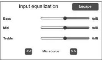 | On this screen page the treble, mid and bass tones level of the input sources can be adjusted.To change the indicated value, slide the cursor along the bar next to each band.Use the << and >> keys to select the source to be equalized among:- Mic source Local microphone- Unit source Microphone unit/s- Aux source Auxiliary input- Ext source Extension card inputTo return to the <AUDIO SETTING > screen, press ‘Escape’. | |
| set> MONITOR SPEAKER Management of monitor speaker Options | ||
| In this panel, besides adjusting the volume of the monitor speaker on the VAIE, input sources, signal on the output zone and Alert / Evac messages can be played back.TheZone monitor speakerenables the output zone to be played back. Press ‘Change’ (A) to select the desired option.TheSource monitor speakerscreen can be opened by clicking on ‘Change’ (B). This screen page enables one of the input sources to be played back; press ‘Change’ (A) to select the desired option.Press ‘Play alarm message’ to open the ‘Alarm Message monitor’ listening screen page. | Selectable zoneOutput on zone 1Output on zone 2Speaker monitor offSelectable sourcesLocal mic.UnitsAuxExtensionEvacAlertChimeSpeaker monitor off | |
| set> PAGING CALLS Management of AUX, MIC and CHIME inputs | ||
| From this panel, it is possible to access the screen page for auxiliary input, local microphone* and warning signal configuration. (see Point set> RACK CONFIG. at page 33).*Only if enabled for broadcasting calls in the system configuration. | ||
| Aux input configuration EscapeOn this screen the configuration of the auxiliary input can be set, selecting the Mode, the hold-on time at the end of a call (Hold on) and the Priority Level of a call.Using the 'Edit zone' button, another screen page is accessed where the call zone can be selected upon activation of the AUX input.NOTE:When the AUX input is set to 'aux input off' mode, it can be used as an input for background music. | ModeAux input offInput VOX level 1÷7Aux input onAux with prec. +Aux with prec.-Hold on0/1/2/4/8/16 sec.Priority level1÷7 | |
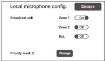 | Local Mic configurationOn this screen, the default output zone for the local microphone broadcasting calls can be set.Press ‘Change’ to select the desired priority level (1+7).NOTE:This screen is available only if this function has been enabled in the system configuration (see Point set>RACK CONFIG. > Local microhone at page 35). | |
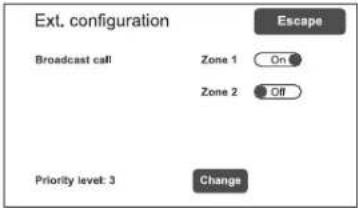 | Ext. configurationBroadcast callIt selects the zone affected by the call coming from the extension card.Priority levelIt selects the priority of calls.If priority is equal to 0, the card doesn't accept external calls and its input can be used as a music source. | |
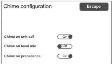 | Chime configurationOn this screen, chimes for calls coming from microphone units, from local microphone or from the precedence contact can be enabled or disabled independently. | Chime on unit call (on/off)Chime on local mic (on/off)Chime on precedence (on/off) |
| display>CLOCK Visualizzazione data e ora | |
| Clock setting Escape Date: 2020 Aug 31, Mon Time: 19:54:06 | Current date and time visualization screen.To set these parameters, please refer to Point set>CLOCK at page 29. |
8.4 MENU
SYSTEM STATUS INSPECTION
This menu is intended for selecting options for system status inspection.
It is for use by the personnel in charge of initial checking of the causes leading to a fault or to an emergency state.
In this menu it is possible to select:
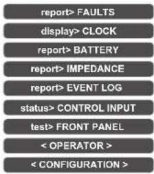
To return to the main screen press Main menu.
| report> FAULTS Investigation on faulty conditions | |
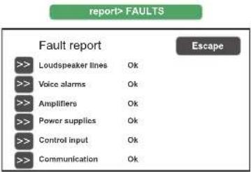 | Six items are listed with a general indication of the fault status.The details of the faulty parts and the status general reporting are shown in the following table.Press the required item to access the chosen sub-menu and view the details of the fault as illustrated on the following screens.To return to the INSPECTION menu press Escape. |
| Label | Category subject to diagnosis | See panel Notes | |
| Loudspeaker lines | Loudspeaker line | 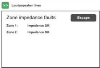 | The diagnosis status is reported for the output line. |
| Voice alarms | Voice emergency sources | 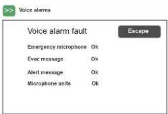 | For each monitored element, the diagnosis status is reported. |
| Amplifiers | Amplifier Loudspeaker line Ground fault | 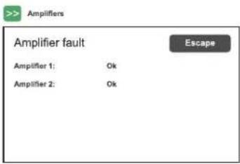 | The diagnosis status is reported for the amplifier. |
| Power supplies | Primary and secondary power suppliesGround fault | Power suppliesPower supply faultEscapeMains OkDC supply Not testedNo gnd fault OkDC/DC converter Ok | The diagnosis status is reported for each monitored element. |
| Control input Local input contacts | Control inputControl input faultEscapeInput 1 FaultInput 2 Ok | The diagnosis status is reported for each monitored element. | |
| Communication | Internal data communication of VAIE | CommunicationCommunications faultsEscapeDSP: communication OKCodec: communication OKDisplay: communication OKFront keys: communication OKSD card: communication OKExt. fault: OK | The diagnosis status is reported for each monitored element. |
report> BATTERY Status of batteries
report>BATTERY
Battery charger report
Battery voltage 26.9 V
Battery current 832 mA
Battery charge 90%
Supply voltage 29 V
Ambient temperature 30 C°
Battery impedance 42 mOhm
Escape
Test
This panel displays all the data relating to power supplies and internal batteries of the VAIE.
The equipment carries out testing of the batteries automatically approximately once an hour. It is in any case possible to start an immediate test manually by pressing the 'Test' key.
To return to the INSPECTION menu, press Escape.
report> IMPEDANCE Impedance of the lines
report>IMPEDANCE
Zone impedance report
Zone 1: out of range
Zone 2: out of range
Escape
(Ref. = out of range)
(Ref. = out of range)
Panel for checking the impedance values measured in real time compared with the value stored during the start-up.
If the tolerance is exceeded, the fault will be reported in the relevant menu together with a too high, too low or short-circuit impedance value.
To return to the INSPECTION menu, press Escape.
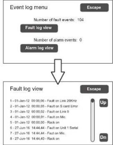
report> EVENT LOG Event log
report> EVENT LOG
Event log menu
Escape
Number of fault events: 104
Fault log view
Number of alarm events: 0
Alarm log view

Fault log view
Escape
1 - 01-Jan-12 00:00,06 - Fault on Link 20KHz 2 - 01-Jan-12 00:00,05 - Fault on S card Error 3 - 01-Jan-12 00:00,02 - Fault on Link 0 4 - 01-Jan-12 00:00,01 - Fault on Mic. 5 - 01-Jan-12 00:00,00 - Rack on 6 - 27-Jun-16 14:44,44 - Fault on Unit 1 Serial 7 - 27-Jun-16 14:44,44 - Fault on Mic. 8 - 27-Jun-16 14:44,40 - Rack on

This panel displays a report showing the total number of faults and alarms recorded during system operation.
Press Fault log view for a detailed view of the faults.
Press Alarm log view for a detailed view of the alarms.
To return to the INSPECTION menu, press Escape.
status> CONTROL INPUT Status of the local input contacts
status>CONTROL INPUT
Control input status
Escape
Input 1 (message): ACTIVE
Input 2 (not used): not active
Input 3 (not used): not active
Input 4 (not used): not active
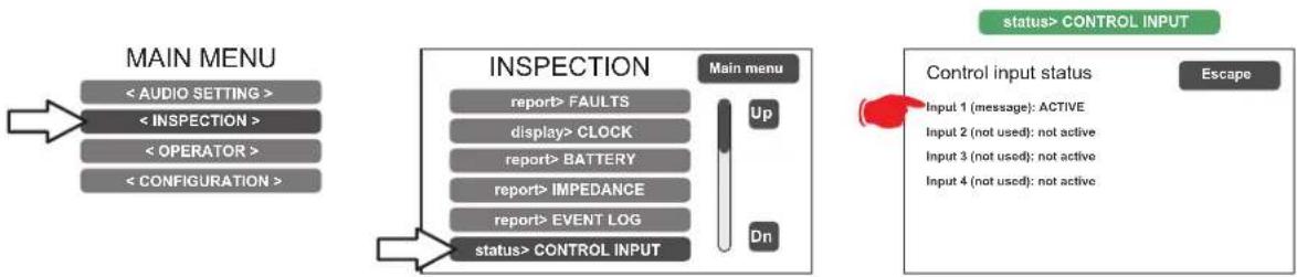
This panel shows a list of the controlled inputs, their types (message, reset, external fault*, not used) and their statuses (input active/not active).
In the event of activation of one of these inputs, the system will enter an "Alarm status", light up the ALARM LED and show automatically the panel indicating which VAIE zones are affected by the emergency (see under Activation of an automatic emergency, page 39).
*The external fault input configuration is useful for reporting the fault of any external equipment to the system.
To return to the INSPECTION menu, press Escape.
test> FRONT PANEL Check of operation of the visual and acoustic signalling devices
test> FRONT PANEL
Press dot for touch calibration test
Press emergency to test beep
Press reset key to exit
Panel for checking operation of the monitor speaker, of the display, of the push buttons, of the touch screen and of the signalling LED for the emergency operations.
All the LEDs, including the emergency button LED, will activate in flashing mode. The screen background colour changes in sequence so as to check correct functioning of all the pixels.
Press the small square that appears on the display to check proper calibration of the touch screen.
Press the EMERGENCY button to test correct sounding of the "beep" by the monitor speaker as well as button efficiency.
Press the RESET button to test correct functioning (return to the INSPECTION menu).
The
8.5 MENU
MANAGEMENT OF EMERGENCY, FAULTY AND DISABLED CONDITIONS
Menu from which to select options, to be used only by the personnel in charge of managing the system in the event of an emergency and/or a fault. If a login password was enabled at the time of configuration, the following panel will appear:
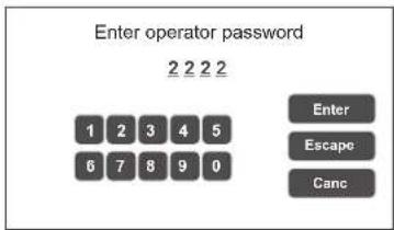
Enter the 4-digit numerical password (it is 2222 by default) and press Enter.
Once the OPERATOR menu is accessed, new items in addition to those already seen will be found.
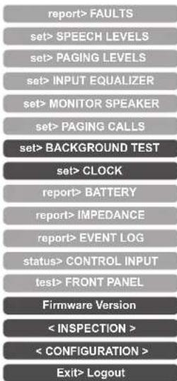
To return to the main screen page press Main Menu.
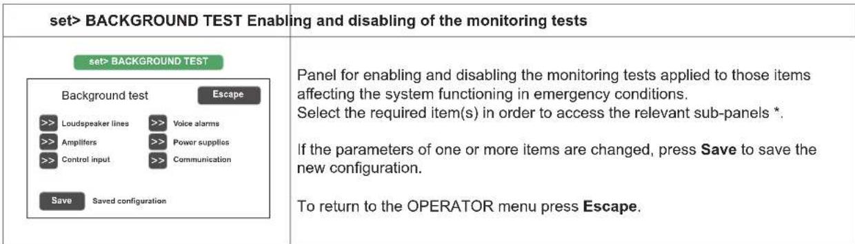
*For details see the table on page 28.
Note:
Upon access to the various panels shown below, the touch screen shows the programming status as currently set. To change this status move the cursors to the desired positions – as indicated in the table - and then press 'Save' on the set> BACKGROUND TEST panel.
| Label Application See panel Notes | |||
| Loudspeaker lines Loudspeaker lines | >> Loudspeaker lines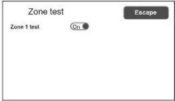 | Panel for testing the loudspeaker line.On = test enabledOff = test disabled | |
| Amplifiers Amplifiers | >> Amplifiers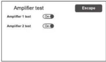 | Panel for testing the local amplifier.On = test enabledOff = test disabled | |
| Control input Controlled input contacts | >> Control input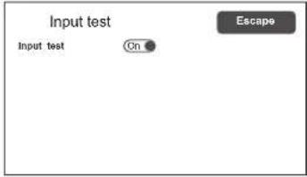 | Panel for testing the input contacts.On = test enabledOff = test disabled | |
| Voice alarms Voice emergency sources | >> Voice alarms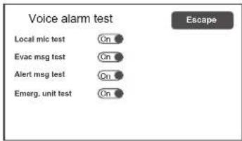 | Panel for testing the incoming emergency sources:- Testing of hand-held micro- Testing of EVAC message- Testing of ALERT message- Test of microphone unitsOn = test enabledOff = test disabled | |
| Power supplies Power supplies | >> Power supplies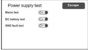 | Panel for testing of power supplies:- Testing of mains supply- Testing of 24 VDC batteries- Testing of GND faultOn = test enabledOff = test disabled | |
| Communication | Internal data communication of VAIE | >> Communication | Panel for testing of internal data communication of VAIE:- Testing of DSP comm.- Testing of codec comm.- Testing of display comm.- Testing of front keys comm.On = test enabledOff = test disabled |
set> CLOCK Setting of system date and time
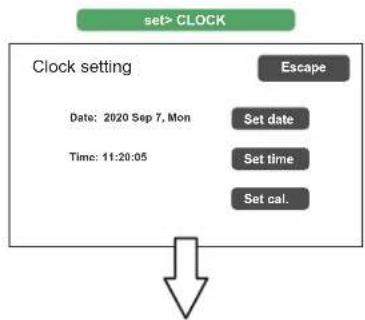
flowchart
graph TD
    A["set> CLOCK"] --> B["Clock setting"]
    B --> C["Escape"]
    B --> D["Set date"]
    B --> E["Set time"]
    B --> F["Set cal."]
    B --> G["Date: 2020 Sep 7, Mon"]
    B --> H["Time: 11:20:05"]
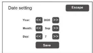
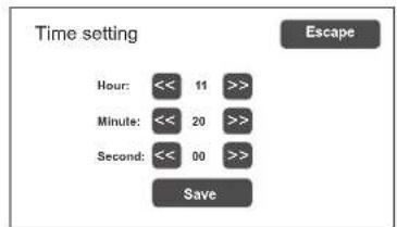
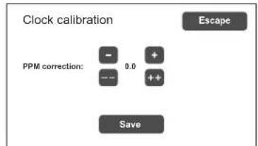
Panel for setting the system date and time.
Press the following buttons:
- Set date
- Set time and
- Set cal. (calibration)
to set these parameters.
To return to the OPERATOR menu press 'Escape'.
After setting the desired date, press 'Save date' before pressing 'Escape' to exit.
After setting the desired time, press 'Save time' before pressing 'Escape' to exit.
The Clock Calibration window enables fine setting of the clock. It is advisable to check the difference in seconds compared with a high-precision clock after a couple of days. Calculate the difference in parts per million (over or under) and enter the result by means of the 'PPM correction' keys. Then press 'Save' to save the setting.
Press 'Escape' to exit.
Firmware Version Viewing the firmware version
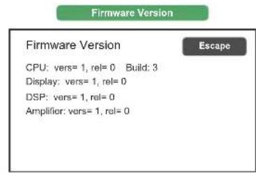
Panel for viewing the version of the firmware installed in the VAIE system.
To return to the OPERATOR menu press 'Escape'.
! N.B.: Upon completion of the operations carried out, before returning to the basic level, that is to say to the MUSIC & PAGING MENU, it is advisable to log out of the system level corresponding to the current menu, so as to reset the required password for future accesses and to prevent unauthorised personnel from accessing the advanced functions of the system.
To do this, select Exit> Logout from the list in the OPERATOR menu.
The system returns to its basic level and shows the MAIN MENU panel. The request for the login password will be reset also for any other levels visited.
8.6 MENU
MANAGEMENT OF ADVANCED SYSTEM FUNCTIONS AND CONFIGURATION CHANGES
This option selection menu is for use only by specifically trained personnel authorised to work on advanced system functions and to modify the configuration parameters, for system start-up and maintenance purposes. If a login password was enabled at the time of configuration, the following panel will appear:
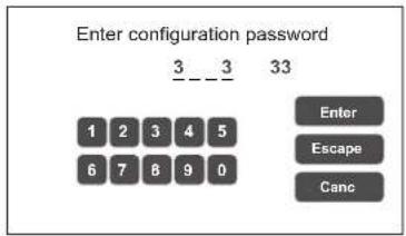
Enter the 4-digit numerical password (it is 3333 by default) and press Enter. Once the CONFIGURATION menu is accessed, additional new items will be seen.
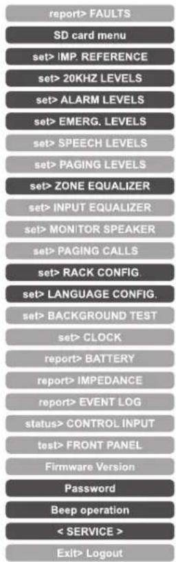
To return to the main screen, press Main Menu.
Fourth access level, included in the CONFIGURATION menu options. Its use is permitted only to those members of the technical service personnel who have appropriate login passwords.
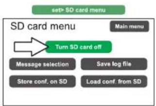
set> SD CARD MENU Setting of emergency messages
flowchart
graph TD
    A["set> SD card menu"] --> B["Main menu"]
    B --> C["Turn SD card off"]
    C --> D["Message selection"]
    C --> E["Save log file"]
    C --> F["Store conf. on SD"]
    C --> G["Load conf. from SD"]
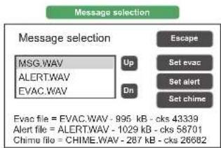
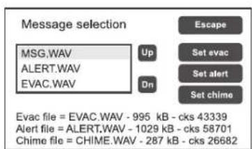
The standard alert and evacuation messages and the broadcast warning signal (chime) are stored at the factory on the SD card mounted on the CPU circuit. In order to customise the system, it is possible, however, to add to and/or update these files. To do so, it is necessary to:
- Place the main thermal-magnetic circuit breaker upstream from the system in the OFF position: the VAIE enters the stand-by mode, exploiting the power supply from the batteries.
- Open the front door of the VAIE by unscrewing the two fixing screws.
- On the display, press the Turn SD card off key: the red LED associated with the card extinguishes. At this point it is possible to extract the SD from the VAIE.
-
Programme the card with the new audio files (max. 20). Following are the requisites of the files, which have to be copied into the root directory of the SD card:
-
Format: *.WAV
• Resolution: 16 bit / mono
• Sampling frequency: 48 kHz - Filename: max 8 characters + .wav extension).
- Once the files have been copied onto the SD card, fit it back onto the CPU circuit and, on the display, press the Turn SD card on key: Check that the red LED lights up again.
- Close the front door of the VAIE, tightening the screws firmly back into place.
- Return the main thermal-magnetic circuit breaker to its ON position.
The SD card is now mounted correctly and the menu on the display shows a list up-dated with the new audio files, which can be browsed using the Up/Dn keys.
To set the new EVACUATION message (EVAC):
Select the desired file and press the Set evac key.
To set the new ALERT message:
Select the desired file and press the Set alert key.
To set the new BROADCAST WARNING SIGNAL (CHIME):
Select the desired file and press the Set chime key.
The names of the files set appear as a reminder at the bottom of the screen, together with the type of use.
The SD card menu screen also shows three other function keys:
- Press the Save log file key to save fault and alarm events file on the SD card (file name: EVENT1.LOG).
- Press the Store conf. on SD key to save the system configuration settings on the SD card.
- Press the Load conf. from SD key to load the previously saved system configuration settings from the SD card.
To return to the SD card menu screen, press Escape once.
To return to the CONFIGURATION menu press Escape twice.
NOTE:
Within the SD card menu, the message playback functions are inhibited; this status is signalled by the fixed lighting of the yellow DIS LED. In order to reactivate the message playback function (DIS led off) it is necessary to exit the SD card menu by pressing Escape.
set> IMP. REFERENCE Impedance acquisition and tolerance setting
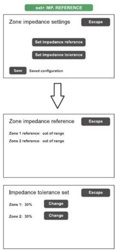
flowchart
graph TD
    A["set> IMP. REFERENCE"] --> B["Zone impedance settings"]
    B --> C["Set impedance reference"]
    C --> D["Set impedance tolerance"]
    D --> E["Save"]
    E --> F["Saved configuration"]
    G["Zone impedance reference"] --> H["Zone 1 reference: out of range"]
    G --> I["Zone 2 reference: out of range"]
    J["Impedance tolerance set"] --> K["Zone 1: 30% Change"]
    J --> L["Zone 2: 30% Change"]
Panel for acquiring line impedance values and setting the tolerance threshold for the diagnostic tests.
Press the appropriate buttons to access the sub-panels.
The Zone impedance reference panel shows the impedance values measured on the output zone, which will constitute the reference values.
Use the Impedance tolerance set panel to define the tolerance, choosing one of the suggested values (press the 'Change' key associated with the desired zone and set one of the following values: 10%, 20%, 30%, 40% or 50%). When the diagnostic system detects a value beyond the tolerance chosen for the reference value, a 'Fault' is activated.
To return to the CONFIGURATION menu, press Escape.
set> 20KHZ LEVELS Setting the test signal level
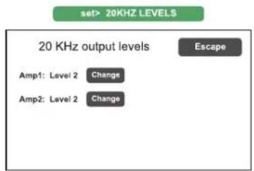
Panel for setting the test signal levels to 20 kHz in the audio channel. Press the Change keys associated with the level to be adjusted and select one of the following options: level 1, level 2, level 3 or Off. The recommended value for the amplifier is 2.
To return to the CONFIGURATION menu, press Escape.
set> ALARM LEVELS Setting the alarm source level
bar
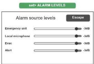
set> ALARM LEVELS | Alarm source levels | Alarm source levels (dB) | | :--- | :--- | | Emergency unit | -3dB | | Local microphone | -3dB | | Evac | -3dB | | Alert | -3dB |Panel for setting the input volume of the alarm sources connected to the VAIE.
- Emergency units.
- Local microphone.
- Evacuation message.
- Alert message.
To return to the CONFIGURATION menu, press Escape.
set> EMERG. LEVELS Setting the zone volume level during emergencies
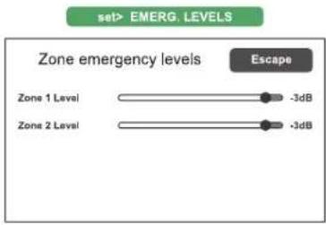
Panel for adjusting the zone volume during emergencies. To return to the CONFIGURATION menu, press Escape.
set> ZONE EQUALIZER Equalisation of the zone tones
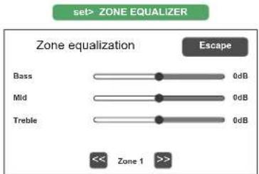
Panel for equalising the bass, mid-range and treble tones in the output zone. To return to the CONFIGURATION menu, press Escape.
set> RACK CONFIG. System configuration
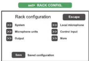
flowchart
graph TD
    A[">> System"] --> B[">> Microphone units"]
    B --> C[">> Output"]
    D[">> Local microphone"] --> E[">> Control input"]
    E --> F[">> More"]
    G["Save"] --> H["Saved configuration"]
    I["Rack configuration"] --> J["Escape"]
This panel contains all the parameters needed for configuring the rack: - System. - Microphone units. - Outputs. - Local microphone. - Controlled inputs. - Optional cards.
Note that any changes whatsoever to any of the sub-panels illustrated on the following page must be saved by pressing the Save button. To return to the CONFIGURATION menu, press Escape.
For the details of the set> RACK CONFIG. panel see the tables on the following pages.
| Label Application See panel Notes | |||
| System | System informationBatteries configuration‘Energy save’ settingEmergency state activation mode | 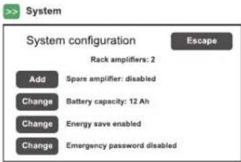 1 AMP (Pmax = 100W)Capacity Duration without mains supply12 Ah 24 h + 30 min*18 Ah 72 h + 30 minN.B.:Regarding particular needs of duration beyondthose foreseen by the current legislation, in 24VDCpower supply conditions, it is possible to use12VDC/26Ah batteries, option selectable from the path:CONFIGURATION > RACK CONFIG >> SYSTEM > BATTERY CAPACITYthen ‘Change’ key to select capacity.However, it is specified that these batteries must bepositioned outside the device as their dimensionsdo not allow them to be housed inside. 1 AMP (Pmax = 100W)Capacity Duration without mains supply12 Ah 24 h + 30 min*18 Ah 72 h + 30 minN.B.:Regarding particular needs of duration beyondthose foreseen by the current legislation, in 24VDCpower supply conditions, it is possible to use12VDC/26Ah batteries, option selectable from the path:CONFIGURATION > RACK CONFIG >> SYSTEM > BATTERY CAPACITYthen ‘Change’ key to select capacity.However, it is specified that these batteries must bepositioned outside the device as their dimensionsdo not allow them to be housed inside. | The total number of amplifierspresent in the system is shown in this panel.By pressing the ‘Change’ keys it is possible to set:- Standby amplifier in place of thesecond zone (VAIE4102 andVAIE4252 models only).- The capacity of the battery(choose 12 or 18 Ah).- ‘Energy save’ mode enabled/disabled. This enables thebatteries to remain in theenergy saving mode whenthere is no mains power.*According to UNI ISO 7240-19,point 5.15.3 requirements:24 h standby plus 30 minutes in vocalalarm condition. |
| Microphone unitsLabel Application See panel Notes | Microphone units configuration | 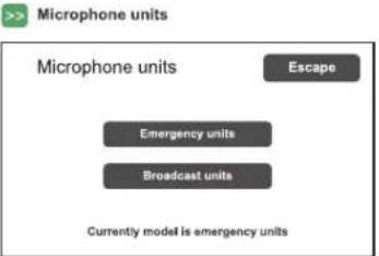 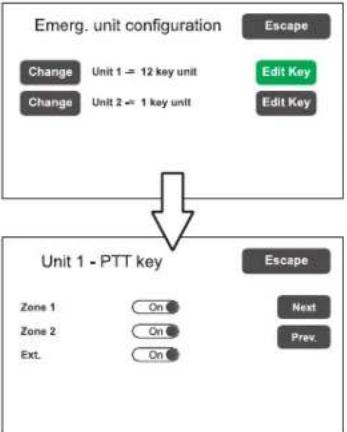 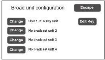 | From this panel it is possible touse the sub-menus to set theconfigurations of the microphoneunits connected to the VAIE:emergency units (max. 2)orbroadcast units (max. 4)To configure the FMD 2000range emergency units, pressEmergency units, then press the‘Change’ key to select the model.(FMD 2001 or FMD 2012).Then press ‘Edit key’ forconfiguring the keys. Use the‘Next’ and ‘Prev.’ keys to passfrom one key to another of theunit.To leave the screen, press‘Escape’.In case the MBT 1106 broadcastunits are connected, press the‘Broadcast unit’ key to accessthe relevant configuration screen. |
| Output Relay outputs | 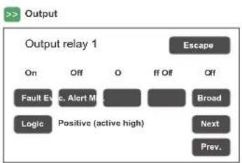 | Panel for configuring the outputs.To go from one output to another(from 1 to 2),press 'Next' or'Prev.'Activate or de-activate (On/Off) the type of event to be associated with the output in question by pressing the appropriate buttons.To leave the screen, press'Escape'. | |
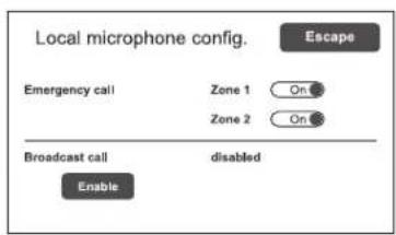
| Local microphone Local microphone | 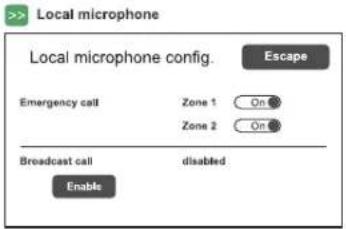 | Panel for configuring the output zone default for emergency messages and emergency or broadcast live calls.Activate or de-activate (On/Off) the emergency calls default.Press 'Enable' to enable the use local microphone for broadcast calls. If enabled, the default setting can be selected in theset>PAGING CALLSmenu (page 23).To leave the screen, press'Escape'. | |
| Control input Controlled input contacts | 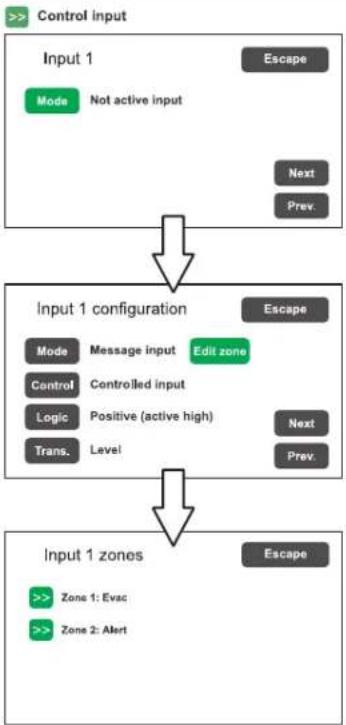 NOTE:The Transition setting can only be enabled ifMessage input mode is on. NOTE:The Transition setting can only be enabled ifMessage input mode is on. | Panel for configuring the controlled inputs. To go from one input to another (from 1 to 4),press Nextor Prev.PressModeto select one of the following modes:-Not active input(not used)-Reset input(reset input)-Message Input >Edit zoneSetting of the messages for the zone (Evac / Alert / No message)-Ext.fault(for the signalling of an external equipment failure to be allowed).PressControlto enable or disable control over the concerned input.PressLogicto set the logic typology attributed to the concerned input, choosing between:-Positive(active high)-Negative(active low)PressTrans.to choose the operating mode:-Level:the messages are activated only for as long as the input is activated.-Transition:activation of the messages starts with activation of the input, but can be stopped only by means of manual resetting or a reset input.Press'Escape' to exit the screen. | |
| More Optional cards selection | 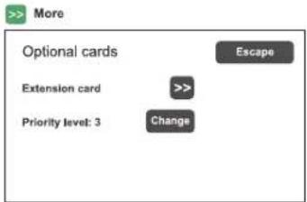 | Press the >> key to enable/ disable the extension card, if present.To set the paramters, refer to set> PAGING CALLS / Ext. configuration on page 23. | |
set> LANGUAGE CONFIG. Selecting the language
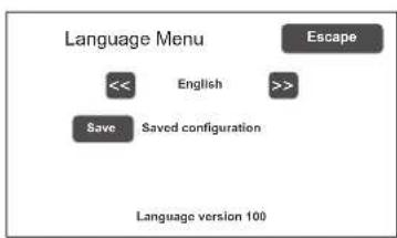
flowchart
graph TD
    A["<<"] --> B["English"]
    B --> C[">>"]
    D["Save"] --> E["Saved configuration"]
    F["Escape"] --> G["Language version 100"]
The factory-set default language is English. The VAIE enables other languages, pre-installed and stored in the internal flash memory, to be chosen.
Use the << and >> keys to browse through the available languages. When the required language is shown, press Save. The new menus will be loaded immediately and the updated screen page will reappear on the display.
To return to the CONFIGURATION menu, press Escape.
Password Setting a password
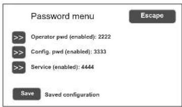
Panel for enabling, disabling and customising the password for logging into the system service levels. The default passwords set are those shown here on the left. To change these settings and enter a new code, press the key associated with the menu in which the change is to be made and, on the next sub-panel, enter the new password.
To correct a typing error, use the Canc key.
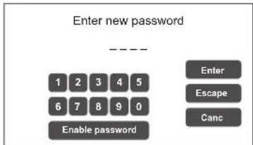
To enable / disable a password, use the Enable password or Disable password keys (as the case may be).
Press Enter to confirm and return to the Password menu panel.
Press Save to save the change made.
To return to the CONFIGURATION menu press Escape.
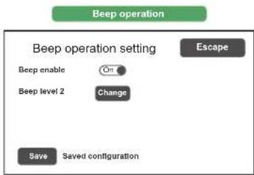
Beep operation Set the control 'beep'
flowchart
graph TD
    A["Beep operation setting"] --> B["Beep enable"]
    A --> C["Beep level 2"]
    A --> D["Change"]
    A --> E["Save"]
    A --> F["Saved configuration"]
    G["Escape"] --> A
From this screen, the acoustic fault (conventionally known as a 'beep') can be set.
- Beep enable / disable:
Move the cursor to the 'On' position (beep enabled) or to the 'Off' position (beep not enabled), as needed (see the "N.B." note below).
- Beep level:
Adjustment of the beep volume, which can be set at one of three different levels (1 / 2 / 3 / Off). Press the Change key until the desired volume is reached.
To return to the CONFIGURATION menu, press Escape.
! N.B.
In order to comply with the regulations, before using the equipment for normal operation it is necessary to enable the acoustic signalling by setting 'Beep enable' to the 'On' position.
8.7 MANUAL EMERGENCY
THE PROCEDURE FOR MANAGING EMERGENCIES IN THE MANUAL MODE (TO BE CARRIED OUT BY AN AUTHORISED OPERATOR) IS DESCRIBED BELOW.
8.7.1 GENERAL INFORMATION
The manual emergency mode can be accessed at any time and has priority both over any pre-recorded messages under way - that may have been activated by an external peripheral unit connected to the controlled inputs (10) - and over any emergency units able to function on the output lines from the VAIE being used.
8.7.2 MANUAL MANAGEMENT OF AN EMERGENCY
The VAIE enables structured management of alarm messages, of their muting and of the selection of zones, as described in greater detail below. Following is a list of operations for a fast approach to manual emergencies.
8.7.3 SENDING OUT OF A LIVE EMERGENCY NOTICE FROM THE VAIE
1) Press the EMERGENCY key (5): when the display shows a confirmation request, press again the EMERGENCY key in order to confirm the emergency state activation (the red LED will light up steadily). The display will now show the output zone of the VAIE. The fact that the system has been placed in a state of emergency is shown simultaneously on any microphone units present in the system.

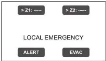
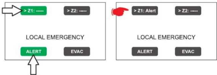
A voice message > Select the zone, then use the hand-held microphone (3) to speak, keeping the button on its side pressed. The red LED ALARM will light up steadily to signal the alarm state (a pre-recorded or live message is present on the zone).
A pre-recorded ALERT message> Select the zone and press ALERT.
A pre-recorded EVACUATION message > Select the zone and press EVAC.
In both cases, the keys on the display will show the type of message being broadcast in the zone.
Note:
If the PTT key of the hand-held microphone or the ALERT or EVAC keys are pressed without selecting any zones beforehand, the message will be sent out as set at the time of system configuration (see set> RACK CONFIG. > Local microphone on page 35). The zones selected at the configuration stage are highlighted by the marker '>' on the keys.
The fault condition of the zone is shown by the yellow colour of the key.
flowchart
graph TD
    A["> Z1: ----"] --> B["LOCAL EMERGENCY"]
    C["> Z2: ----"] --> B
    D["> Z1: Alert"] --> E["LOCAL EMERGENCY"]
    F["> Z2: ----"] --> E
    G["> Z1: Alert"] --> H["LOCAL EMERGENCY"]
    I["> Z2: ----"] --> H
    J["> Z1: Alert"] --> K["LOCAL EMERGENCY"]
    L["> Z2: ----"] --> K
    M["> Z1: Alert"] --> N["LOCAL EMERGENCY"]
    O["> Z2: ----"] --> N
    P["> Z1: Alert"] --> Q["LOCAL EMERGENCY"]
    R["> Z2: ----"] --> Q
    S["> Z1: Alert"] --> T["LOCAL EMERGENCY"]
    U["> Z2: ----"] --> T
    V["> Z1: Alert"] --> W["LOCAL EMERGENCY"]
    X["> Z2: ----"] --> W
    Y["> Z1: Alert"] --> Z["LOCAL EMERGENCY"]
    AA["> Z2: ----"] --> Z
    AB["> Z1: Alert"] --> AC["LOCAL EMERGENCY"]
    AD["> Z2: ----"] --> AC
    AE["> Z1: Alert"] --> AF["LOCAL EMERGENCY"]
    AG["> Z2: ----"] --> AF
    AH["> Z1: Alert"] --> AI["LOCAL EMERGENCY"]
    AJ["> Z2: ----"] --> AI
    AK["> Z1: Alert"] --> AL["LOCAL EMERGENCY"]
    AM["> Z2: ----"] --> AL
    AN["> Z1: Alert"] --> AO["LOCAL EMERGENCY"]
    AP["> Z2: ----"] --> AO
Nota:
A message sent via the hand-held microphone has top priority over the pre-recorded evacuation and alert messages. In the event of simultaneous selection, an EVAC message always has priority over an ALERT message.
The playing out of pre-recorded messages - even if activated by controlled inputs - can be silenced by pressing for more than 3 seconds the RESET key (4).
3) To end the state of emergency, press the EMERGENCY key (5) again.
8.7.4 SENDING OUT OF A LIVE EMERGENCY NOTICE FROM REMOTE STATIONS
1) Lift the safety lid on the station and press the EMERGENCY key once. It lights up steadily. The fact that the system has been placed in a state of emergency by the station is shown also on any other stations and on the VAIE (with a flashing red LED).
2) Select the zones where the message should be sent.
3) Activate the EVAC message or the ALERT message by means of the appropriate button or speak through the microphone keeping the PTT key pressed until the end of the message.
Note: The P.T.T. key has priority over any pre-recorded messages being sent out.
4) If necessary, repeat the sequence of points 2) and 3) above several times.
Note: RESET/ACK key (microphone unit) / RESET key (VAIE fron panel) have the same functional features.
5) To end the state of emergency, press EMERGENCY button again.
8.7.5 EXIT OF THE SYSTEM FROM MANUAL MANAGEMENT OF AN EMERGENCY
At the end of the procedure for managing a Manual Emergency, press the red EMERGENCY key, which will extinguish and – if there is no activation taking place from external peripheral units connected to the controlled input contacts – the system will return automatically to its Idle state, displaying the MUSIC & PAGING screen.
The ALARM LED will extinguish to indicate that the VOICE ALARM has been deactivated.
Once the emergency state is over, all the manually pre-activated messages will be deactivated. The messages related to controlled inputs will remain active: if any of controlled inputs have been activated, the EMERGENCY button will start to flash and the system will remain in a state of Automatic Emergency, resuming the broadcasting of the messages in the zone, depending on how the activated inputs were programmed.
8.8 AUTOMATIC EMERGENCY - ALARM STATUS ACTIVATED BY AN EXTERNAL PERIPHERAL UNIT
THE PROCEDURE FOR MANAGING AN EMERGENCY STATUS SET OFF BY AN EXTERNAL PERIPHERAL UNIT THAT ACTIVATES THE INPUT CONTACTS PROGRAMMED TO ENABLE THE "ALARM STATUS" IS DESCRIBED BELOW.
8.8.1 ACTIVATION OF AN AUTOMATIC EMERGENCY
In the event of activation of a programmed input contact the VAIE stops its 'Idle' state normal activity, mutes the music being broadcast, inhibits operation of the PA sources for broadcasting announcements and shows the AUTOMATIC EMERGENCY screen, which indicates the type of message being sent out to the zones:
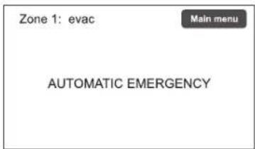
To see rapidly which input is activating the emergency, press the Main Menu key to return to the main panel, then go to the INSPECTION menu and select the item status> CONTROL INPUT:
flowchart
graph TD
    A["MAIN MENU"] --> B["INSPECTION"]
    B --> C["control input status"]
    C --> D["Main menu"]
    D --> E["control input status: Input 1 (message): ACTIVE, Input 2 (not used): not active, Input 3 (not used): not active, Input 4 (not used): not active"]
    B --> F["control input status: control input"]
    B --> G["control input status: control input"]
    B --> H["control input status: control input"]
    B --> I["control input status: control input"]
    B --> J["control input status: control input"]
    B --> K["control input status: control input"]
    B --> L["control input status: control input"]
    B --> M["control input status: control input"]
    B --> N["control input status: control input"]
    B --> O["control input status: control input"]
    B --> P["control input status: control input"]
    B --> Q["control input status: control input"]
    B --> R["control input status: control input"]
    B --> S["control input status: control input"]
    B --> T["control input status: control input"]
    B --> U["control input status: control input"]
    B --> V["control input status: control input"]
    B --> W["control input status: control input"]
    B --> X["control input status: control input"]
    B --> Y["control input status: control input"]
    B --> Z["control input status: control input"]
    B --> AA["control input status: control input"]
    B --> AB["control input status: control input"]
    B --> AC["control input status: control input"]
    B --> AD["control input status: control input"]
    B --> AE["control input status: control input"]
    B --> AF["control input status: control input"]
    B --> AG["control input status: control input"]
    B --> AH["control input status: control input"]
    B --> AI["control input status: control input"]
    B --> AJ["control input status: control input"]
    B --> AK["control input status: control input"]
    B --> AL["control input status: control input"]
    B --> AM["control input status: control input"]
    B --> AN["control input status: control input"]
    B --> AO["control input status: control input"]
    B --> AP["control input status: control input"]
    B --> AQ["control input status: control input"]
    B --> AR["control input status: control input"]
    B --> AS["control input status: control input"]
    B --> AT["control input status: control input"]
    B --> AU["control input status: control input"]
    B --> AV["control input status: control input"]
    B --> AW["control input status: control input"]
    B --> AX["control input status: control input"]
    B --> AY["control input status: control input"]
    B --> AZ["control input status: control input"]
    B --> BA["control input status: control input"]
    B --> BB["control input status: control input"]
    B --> BC["control input status: control input"]
    B --> BD["control input status: control input"]
    B --> BE["control input status: control input"]
    B --> BF["control input status: control input"]
    B --> BG["control input status: control input"]
    B --> BH["control input status: control input"]
    B --> BI["control input status: control input"]
    B --> BJ["control input status: control input"]
    B --> BK["control input status: control input"]
    B --> BL["control input status: control input"]
    B --> BM["control input status: control input"]
    B --> BN["control input status: control input"]
    B --> BO["control input status: control input"]
    B --> BP["control input status: control input"]
    B --> BQ["control input status: control input"]
    B --> BR["control input status: control input"]
8.8.2 VIEWING THE OPERATIONAL STATUS
The condition of active VOICE ALARM - live announcement via the microphone or pre-recorded message under way - is shown by the red ALARM LED lighting up on the front panel of the VAIE.
8.8.3 SYSTEM OPERATION DURING AN AUTOMATIC EMERGENCY
As long as the input contacts remain active, the MUSIC & PAGING MENU panel continues to be deactivated, however it is in any case possible to navigate through the various menus containing options for accessing advanced system functions and to inspect or change their settings.
The current "Alarm Status" due to the Automatic Emergency can be changed by an authorised operator, who can take steps to activate the manual controls for managing the system emergency in order to mute the messages by holding the RESET key (4) down for at least 3 seconds, to change those under way or to send out live announcements with the microphone.
For details concerning the Manual Emergency mode, see the appropriate section (page 37).
8.8.4 EXITING FROM AN AUTOMATIC EMERGENCY
Exit from an Automatic Emergency takes place when no input contact is active.
The system will return to the 'Idle State', displaying the MUSIC & PAGING MENU panel.
Note: The inputs configured in Transition mode can only be stopped by means of MANUAL RESETTING or by a RESET input. This operation can be carried out on the VAIE front panel or via the emergeny unit.
9. FAILURE STATUS
THE VAIE HAS DIAGNOSTIC ROUTINES THAT MONITOR CONTINUOUSLY THE AVAILABILITY OF EMERGENCY SOURCES AND THE INTEGRITY OF CRITICAL PATHS OF THE SIGNALS ENSURING SYSTEM OPERATION IN EMERGENCY CONDITIONS.
9.1 SYSTEM OPERATION AND SIGNALLING IN A GENERIC FAILURE CONDITION
- SYSTEM SIGNALLING DUE TO AN EXISTING "FAILURE CONDITION"
When the monitoring system detects a fault during the normal "Idle State" operation, it promptly activates signalling of the "Failure Condition" as follows:
- the FAULT LED lights up (visual signalling).
- sending out of a beep by the VAIE monitor speaker and by the microphone units buzzer (acoustic signal).
- activation of the local output contacts, if programmed to send signals to an external peripheral unit.
- location of the fault (FAULT): the faulty device and the type of fault are shown on the menu pages under the item report> FAULTS.
- SYSTEM SIGNALLING FOR RESUMPTION FOLLOWING A "FAILURE CONDITION"
If the cause of the fault no longer exists, the system resumes automatically its "Idle State", deactivating all the above signalling and storing the information concerning the last fault. The word RESUMED is shown in the menu pages under the item report>FAULTS referred to operation of the device that was previously faulty.
- CANCELLING THE ACOUSTIC FAULT SIGNALLING AND OPERATION RESUMPTION SIGNALLING To silence the acoustic signalling of a current fault:
- go to the INSPECTION, OPERATOR or CONFIGURATION menus.
- press the RESET button briefly to halt the beep.
To cancel the signalling of the fault of which a report has been stored and that no longer exists (operation has been RESUMED), there must be no faults under way or the beep must already have been stopped. Therefore:
- go to the INSPECTION, OPERATOR or CONFIGURATION menus.
- press the RESET button briefly to reset all the signalling of faults after which operation has been 'RESUMED'.
Note: In the event of a fault of a loudspeaker line due to a short circuit, once the line has been repaired, it is necessary to carry out a MANUAL RESET in order to re-activate the audio signal on the output of the concerned line:
- Go to the OPERATOR menu or to the CONFIGURATION menu.
- Select the report> FAULTS menu followed by >>Loudspeaker line. Then, on the 'Fault zone impedance report' screen, press the RESET key and hold it down for at least two seconds.
9.2 SYSTEM OPERATION AND SIGNALLING WITH A FAULT ON A LOUDSPEAKER LINE
A fault on a loudspeaker line may be due to any of several causes, such as high impedance, low impedance or a short circuit. If it is a matter of a change in the impedance, the VAIE continues to send out the zone output audio signal. If there is a short circuit, an overload protection of the amplifier could occur, while maintaining the failure condition on.
- TECHNICAL SPECIFICATIONS
| MODELLO VAIE4101 VAIE4102 VAIE4251 VAIE4252 | ||||
| Rated audio output @230 VAC | 100 W 250 W | |||
| Rated audio output @24 Vdc | 85 W (THD=10%) 200 W (THD=10%) | |||
| Rated audio output @21,5 Vdc | 68 W (THD=10%) 158 W (THD=10%) | |||
| Display 4.3", backlit with touch screen, 480x272 pixels | ||||
| No. of zones/amplifiers 1 2 1 2 | ||||
| Inputs | ||||
| Emergency microphone• Sensitivity / Impedance• Frequency response• S/N ratio | Dynamic XLR-F w/P.T.T. (Push To Talk) on the front doorSignal level: 20 mV / 10 kΩ110 ÷ 10.000 Hz61 dB | |||
| Paging / Emergency units (UNIT)• Sensitivity / Impedance• Frequency response• S/N ratio | 1 off Rj45 for paging units (PA) or emergency units (VES)Signal level: max. 850 mV / 8 kΩ60 ÷20.000 Hz84 dB | |||
| AUX INPUT (LINE VOX) / MUSIC• Sensitivity / Impedance• Frequency response• S/N ratio | Balanced with terminals (HOT-COM-GND)Programmable in ON / OFF / VOX with A.P.T. modesPrecedence input with contact closing activation160 mV / 40 kΩ40 ÷ 20.000 Hz73 dB | |||
| Outputs | ||||
| Constant voltage outputs | 1 zone A/Bfor 100V linesMinimum 100 Ω | 2 zones A/Bfor 100V linesMinimum 100 Ω | 1 zone A/Bfor 100V linesMinimum 40 Ω | 2 zones A/Bfor 100V linesMinimum 40 Ω |
| Emergency controls• Controlled inputs (IN1÷IN4)• Outputs R1, R2 | Programmable for normally active or normally inactive state4 off inputs with diagnostic2 off relays for signalling, state of emergency and faults (24 Vdc / 1 A each)N.O-N.C-Exchange state | |||
| General information | ||||
| Mains power supplyConsumption @230 VAC | 230 VAC 50/60Hz +10/-15% | |||
| 130 W full load / 22 W quiescent 330 W full load / 33 W quiescent | ||||
| Secondary power supplyConsumption @24 Vdc | 24 Vdc (2x 12 Vdc batteries) | |||
| 4,2 A full load660 mA quiescent0,22 A energy saving | 9,8 A full load940 mA quiescent0,22 A energy saving | |||
| Batteries (see page 34 for details) | 12 Ah - Ri max. 250 mΩ | 24 h in standby + 1/2 h with full power alarm message | ||
| 18 Ah- Ri max. 167 mΩ | 72 h in standby + 1/2 h with full power alarm message | |||
| Charger / Power supply unit | 2.5 A (I max. a)5 A (I max. b) | 9 A (I max. a)11 A (I max. b) | ||
| 21 V (final voltage - detached battery)27,2 V (complete load voltage) | ||||
| Internal fuses V~ 2AT | L / V--- 10ATL | |||
| Environmental operating conditions | Temperature: +5°C ÷ +40°C | Relative humidity: 25% to 75% (non-condensing) | |||
| Type of mounting | Wall mounting | |||
| Dimensions (W x H x D) | 360 x 495 x 193 mm | |||
| Net weight (without batteries) | 11,5 kg | |||
LIST OF OPTIONAL FUNCTIONS
| CLAUSE DESCRIPTION | |
| 7.6.2 Manual muting of voice alarm condition | |
| 7.7.2 Manual resetting of voice alarm condition | |
| 7.9 Output for signalling a voice alarm condition | |
| 8.3 Indication of fault affecting the transmission paths | |
| 8.4 Indication of fault affecting the alarm zones | |
| 10 Manual control of voice alarms | |
| 11 Interface for external control device(s) | |
| 12 Emergency microphone(s) |
LIST OF THE AUXILIARY FUNCTIONS
| DESCRIPTION |
| Broadcast calls |
| Background music |

21
FBT S.p.A.
Via Paolo Soprani 1 - 62019 RECANATI - ITaly
0068
0068/CPR/163-2021
EN54-4:1997 + A1:2002 + A2:2006
EN 54-16:2008
Voice alarm control and indicating equipment for fire detection and fire alarm system with integrated power supply
VAIE2101-V, VAIE2102-V, VAIE2251-V, VAIE2252-V
Provided options:
| 7.6.2 | Manual muting of voice alarm condition |
| 7.7.2 | Manual resetting of voice alarm condition |
| 7.9 | Output for signalling a voice alarm condition |
| 8.3 | Indication of fault affecting the transmission paths |
| 8.4 | Indication of fault affecting the alarm zones |
| 10 | Manual control of voice alarms |
| 11 | Interface for external control device(s) |
| 12 | Emergency microphone(s) |

- COLLEGAMENTI
- IMPORTANTE
- Energy save (enabled/disabled)
- Emergency password (enabled/disabled)
- Escape
- Test
- report> EVENT LOG Storico eventi
- EMERGENZA MANUALE
- Compact wall-mount evacuation systems
- WARRANTY
- TABLE OF CONTENTS
- WARNINGS 48
- INTRODUCTION
- GENERAL DESCRIPTION
- INSTALLATION AND CONNECTIONS
- Wall mounting
- Connections
- OPERATIONAL CONDITIONS AND TERMINOLOGY
- DEFINITIONS
- MENU STRUCTURE
- USING THE SYSTEM
- FAILURE STATUS
- TECHNICAL SPECIFICATIONS
- WARNINGS
- POWER SUPPLY AND EARTHING
- ! N.B. – FEATURES OF THE WIRING SYSTEM
- ! N.B.
- SAFETY NOTES
- MAINTENANCE
- OVERVIEW OF THE SYSTEM
- FUNCTIONAL FEATURES
- TYPICAL CONFIGURATION
- FRONT PANEL
- N.B.
- CONNECTION OF AUXILIARY/MUSIC INPUT
- CONNECTION OF MICROPHONE UNITS
- CONNECTION OF RELAY OUTPUTS
- CONNECTION OF INPUT CONTACTS
- CONNECTION OF THE STANDBY AMPLIFIER
- CONNECTION OF THE EXTENSION CARD
- CONNECTION OF POWER SUPPLIES
- SIGNALLING OF OPERATING CONDITIONS
- Emergency Source
- Priority
- NOTA
- MENU | BASE LEVEL
- A) Password
- B) Muting the BEEP
- C) Acquisition of impedances
- D1) >> System
- D2) >> Microphone units
- Emergency units Configuration of the keys for FMD 2000 range emergency units
- D5) >> Control input
- E) Emergency messages
- MUSIC & PAGING MENU
- MENU
- MENU
- SYSTEM STATUS INSPECTION
- report> BATTERY Status of batteries
- report>BATTERY
- report> IMPEDANCE Impedance of the lines
- report>IMPEDANCE
- report> EVENT LOG Event log
- report> EVENT LOG
- Fault log view
- status> CONTROL INPUT Status of the local input contacts
- status>CONTROL INPUT
- test> FRONT PANEL Check of operation of the visual and acoustic signalling devices
- test> FRONT PANEL
- MENU
- Note:
- set> CLOCK Setting of system date and time
- Firmware Version Viewing the firmware version
- MENU
- set> SD CARD MENU Setting of emergency messages
- set> IMP. REFERENCE Impedance acquisition and tolerance setting
- set> 20KHZ LEVELS Setting the test signal level
- set> ALARM LEVELS Setting the alarm source level
- set> LANGUAGE CONFIG. Selecting the language
- Password Setting a password
- Beep operation Set the control 'beep'
- MANUAL EMERGENCY
- GENERAL INFORMATION
- MANUAL MANAGEMENT OF AN EMERGENCY
- SENDING OUT OF A LIVE EMERGENCY NOTICE FROM THE VAIE
- Nota:
- SENDING OUT OF A LIVE EMERGENCY NOTICE FROM REMOTE STATIONS
- EXIT OF THE SYSTEM FROM MANUAL MANAGEMENT OF AN EMERGENCY
- AUTOMATIC EMERGENCY - ALARM STATUS ACTIVATED BY AN EXTERNAL PERIPHERAL UNIT
- ACTIVATION OF AN AUTOMATIC EMERGENCY
- VIEWING THE OPERATIONAL STATUS
- SYSTEM OPERATION DURING AN AUTOMATIC EMERGENCY
- EXITING FROM AN AUTOMATIC EMERGENCY
- SYSTEM OPERATION AND SIGNALLING IN A GENERIC FAILURE CONDITION
- SYSTEM OPERATION AND SIGNALLING WITH A FAULT ON A LOUDSPEAKER LINE
Brand : FBT
Model : VAIE 4000
Category : Alarm system