
CAFG91X - Oven Artusi - Free user manual and instructions
Find the device manual for free CAFG91X Artusi in PDF.


| Product Type | Freestanding gas cooker with electric oven |
| Brand | Artusi |
| Model | CAFG91X |
| Width | 895 mm |
| Depth | 729 mm |
| Height (overall) | Approx. 900 mm (adjustable legs) |
| Hob Type | Gas (5 burners: Triple Crown, Quick, Semi-quick, Auxiliary) |
| Oven Type | Multifunction electric oven |
| Gas Types | Natural Gas (1.00 kPa) and ULPG (2.75 kPa) – convertible |
| Power Supply | 220–240 V, 15 A, earthed |
| Oven Functions | Fan Oven, Lower, Bake, Fan Bake, Light, Defrost, Fan Grill, Medium Grill, Grill |
| Rotisserie | Optional accessory (rotary spit) |
| Safety Features | Anti-tilt chains (mandatory installation), child safety warnings |
| Cleaning | Hand wash removable burner caps; mild detergent for oven interior; avoid abrasives |
| Oven Door | Removable inner glass for cleaning |
| Warranty | 24 months for freestanding models (900 mm width) |
| Country of Origin | China (manufactured by Guangdong Midea) |
| Standards | AS5601/AG 601, AS/NZS 3000, WEEE compliant |
| Accessories Included | Baking and roasting shelf, enamelled baking tray, rotary spit |
| Installation Requirements | Must be installed by qualified person; adequate ventilation required |
Frequently Asked Questions - CAFG91X Artusi
User questions about CAFG91X Artusi
0 question about this device. Answer the ones you know or ask your own.
Ask a new question about this device
Download the instructions for your Oven in PDF format for free! Find your manual CAFG91X - Artusi and take your electronic device back in hand. On this page are published all the documents necessary for the use of your device. CAFG91X by Artusi.
USER MANUAL CAFG91X Artusi
CAFG9OX
CAFG91X
CAFG91B
Congratulations, you are now the proud owner of an ARTUSI cooking appliance. Thank you for purchasing ARTUSI and welcome to the ARTUSI Family.
This instruction manual has been specially created to inform you of the full range of features your ARTUSI appliance has to offer and serves as an introduction to getting the very best out of your ARTUSI appliance.
We present detailed information on each of the features your ARTUSI appliance consists of. Once you have read this section you will be able to choose the most appropriate settings for your appliance when cooking different types of food.
We ask you to read the instructions in this booklet very carefully as this will allow you to get the best results from using your appliance. KEEP THE DOCUMENTATION OF THIS PRODUCT FOR FUTURE REFERENCE.
TO REGISTER YOUR PRODUCT WITH ARTUSI, PLEASE FILL OUT THE WARRANTY CARD AT THE END OF THIS BOOKLET AND POST IT TO: REPLY PAID 83617
LEICHHARDT NSW 2040
Dear Artusi Customer, please read this user manual carefully before using the product and, keep it permanently at your disposal.
Note: This user manual is prepared for more than one model. Some of the features specified in this Manual may not be available on your appliance.
All our appliances are only for domestic use, not for commercial use. Products marked with (*) are optional.
"THIS APPLIANCE SHALL BE INSTALLED IN ACCORDANCE WITH THE REGULA TIONS FORCE AND ONLY USED IN A WELL VENTILATED SPACE. READ THE INSTRUCTIONS BEFORE INSTALLING OR USING THIS APPLIANCE"
"Conforms with the WEEE Regulations."
RECORD HERE FOR EASY REFERENCE
Model ____ Colour ____
Serial Number ____ Installation Date ____
Dealer's Name and Address ____ ____
GENERAL INFORMATION
ENVIRONMENTAL WARNING
Waste packaging

Do not throw the packaging of your appliance into the dustbin, but pick out the different materials (for instance foil, paperboard, polystyrene) according to the local rules for rubbish elimination.
This appliance must only be used for the purpose of domestic cooking.
Getting to know your new cooker
Thank you for choosing one of our products.
Our cookers are of simple, rational design. They are constructed to the best standards to ensure good service and outstanding safety.
Please read this manual carefully; it will provide all the advice needed to allow you to obtain the best results from the very first day.
ATTENTION:
- Before using the appliance, do not forget to remove the plastic protective film from parts of the appliance.
WARNING
Accessible parts will become hot when in use. To avoid burns and scalds children should be kept away.
WARNING
In order to prevent accidental tipping of the appliance, for example by a child climbing onto the open oven door, the stabilizing means must be installed.
WARNING
This appliance is not intended for use by persons (including children) with reduced physical, sensory or mental capabilities, or lack of experience and knowledge, unless they have been given supervision or instruction concerning use of the appliance by a person responsible for their safety. Children should be supervised to ensure that they do not play with the appliance.
Young children and infirm persons should not be left unsupervised in the vicinity.
WARNING
Before you use the appliance for the first time, check that the plastic films protecting some parts (fascia panel, parts in stainless steel, etc.) have been removed.
WARNING:
A steam cleaner is not to be used cleaning this appliances.
WARNING
DO NOT USE OR STORE FLAMMABLE MATERIALS IN THE APPLIANCE STORAGE DRAWER OR NEAR THIS APPLIANCE.
DO NOT SPRAY AEROSOLS IN THE VICINITY OF THIS APPLIANCE WHILE IT IS IN OPERATION.
WHERE THIS APPLIANCE IS INSTALLED IN MARINE CRAFT OR IN CARAVAN, IT SHALL NOT BE USED AS A SPACE HEATER
DO NOT MODIFY THIS APPLIANCE.
WHEN YOU CALL FOR SERVICE
When you call for service or order parts for your unit, be sure to give:
- MODEL
- SERIAL NUMBER
- COLOUR
- PART NAME and/or description of problem
- YOUR FULL NAME, ADDRESS, and HOME TELEPHONE NUMBER and BUSINESS TELEPHONE NUMBER IF APPROPRIATE.
Servicing shall be carried out only by authorised personnel.
SECTION FOR THE QUALIFIED TECHNICIAN
OVERALL DIMENSIONS
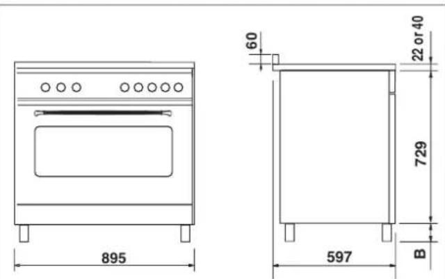
B = adjustable height (100/167mm)
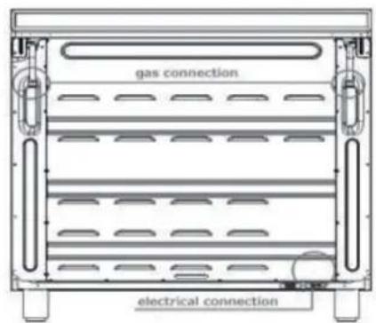
INSTALLATION
PROVISION FOR VENTILATION
The room where the Cooker is installed should have permanent ventilation as follows:
"Ventilation must be in accordance with AS5601/AG 601 - Gas Installations. In general, the appliance should have adequate ventilation for complete combustion of gas, proper flueing and to maintain temperature of immediate surroundings within safe limits. "Do not install in a bed-sitting room, a bathroom or shower room.
If there is another fuel burning appliance in the same room, a higher level of ventilation will be required, you should consult - "the safety requirements".
In addition to the above, during prolonged use, opening a window in the same room is recommended. This will avoid the build up of excessive moisture and condensation.
POSITIONING
Important: Fix the chain located next to the gas connection on both sides of the cooker to the wall to prevent the cooker from tilting. Both chains must be securely fixed.
Make sure that the wall surface behind the Cooker is non-combustable (will not catch fire).
Where a painted surface is adjacent, a fire retardant paint surface is recommended. Wallpaper, wood, or fabric should not be used behind or next to the cooker.
Clearances to combustible materials
"Any adjoining wall surface (side or rear) situated within 200mm of any hob burner must be a suitable non-combustible material from the edge for a height of 150mm for the entire length of the cooker.
Any combustible construction above the cooker must be at least 650mm above the maintop." Ensure that a power and gas supply are nearby. The Cooker should be located carefully so that the heat produced by it has plenty of space to escape. The diagram below shows an ideal configuration.
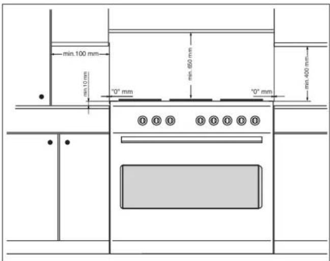
No part of any adjoining wall surface can be made of combustible materials. The protection of combustible materials required by Clause 5.12.1.1 of AS5601-2004 is the fixing of 5 mm thick ceramic tiles to the surface or attaching fire resistant material to the surface and covering with sheet metal with a minimum thickness of 0.4 mm.
Clearances to non-combustible materials
"If the cooker is being fitted next to cupboards or adjoining wall surfaces, which are within 200mm from the edge of the hob burner and of a suitable non-combustible material as specified in AS5601, then ensure that a distance of at least 6cm is left between the edge of the cooker and the non-combustible material. This gap is to allow plenty of space for the heat produced by the cooker to escape on each side of the cooker."
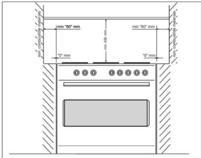
Note:
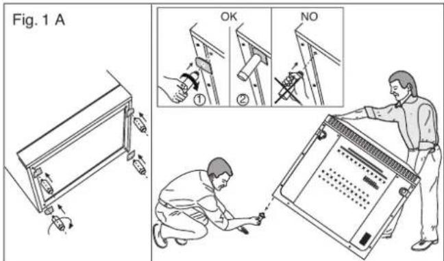
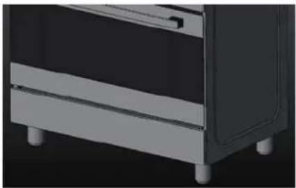
The cooker is fitted with 4 legs for an eventual alignment in height with the furniture (fig. 1 A).
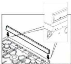
Fitting the splash guard
natural_image
Technical diagram of a mechanical assembly with arrows indicating direction (no text or symbols present)Depending on the model.
Proceed as follows:
- Remove the packaging and the protective film from the splash guard.
- Screw the splash guard onto the rear of the appliance using the 2 bolts.
• Not permitted use with lids or covers aftermarket
To fix the cooker to the rear wall (anti-tilting chain/hose restraining chain)
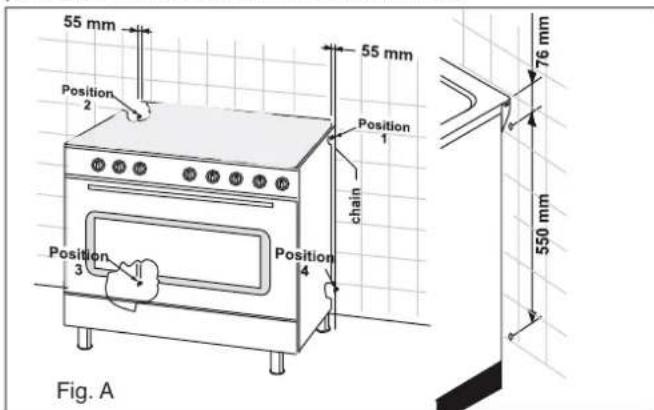
WARNING - For safety reasons and to prevent tipping of the appliance, these stabilizing means must be installed. The cooker is equipped with 2 chains fixed on each side at the rear of the cooker near the top (see Fig. A). The chains are fitted with "spring clips" which must be clipped to the "screw eyes" provided with the cooker. Install the "screw eyes" as follows:
- Drill four 6mm holes (position 1 - 2 - 3 - 4) in the wall as in Fig. A.
- Insert part "R" into the holes then screw in the "screw eyes" part "G" see Fig. B.
Note: If the part provided is not suitable for the wall material please use an appropriate device to ensure secure holding of the "screw eyes" to the wall. - Bring the cooker near the wall and clip the chains on the "screw eyes" as in Fig. C.
IMPORTANT: If the cooker is moved for any reason (e.g. maintenance) resulting in the cooker being unclipped from the wall, the cooker must be re-clipped to the wall at the completion of the task.
A chain should be fitted by the installer within 50mm of the hose e connection point to prevent strain on the hose when the cooker is pulled forward. The chain should restrict the appliance movement to no more than 80% of the hose length. After the chain is installed, check that there is no strain on the hose or gas connections when the cooker is pulled as far forward as the chain allows.
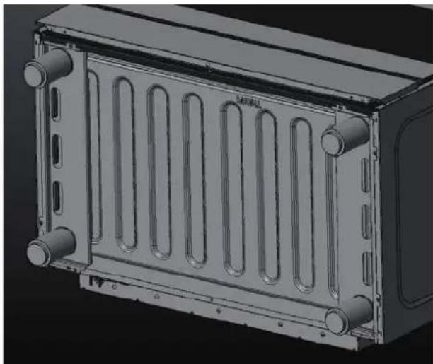
Instruction assembly crossbar reinforced legs
- Recline the cooker on the back as (This must be done by two operators)
- Remove two screws from the front frame.
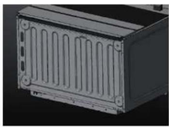
natural_image
3D rendering of a rectangular electronic device with ventilation slots and mounting holes (no text or symbols visible)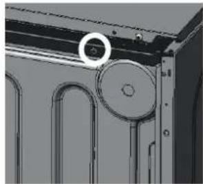
natural_image
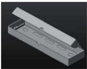
Close-up of a mechanical component with a circular feature and curved cutouts (no visible text or symbols)- Take the two reinforcement bars from the box positioned inside the cavity of the oven
- Place the two reinforcement bars as the image (The two reinforcement bars are ambidextrous)
- Fix the two reinforcement bars with the screws provided (4 screws each reinforcement bars)
natural_image
3D rendering of a mechanical component with mounting holes and a sloped top (no text or symbols)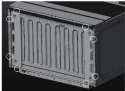
natural_image
3D rendering of a rectangular electronic device with ventilation slots and mounting holes (no text or symbols visible)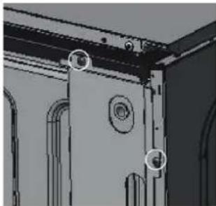
natural_image
Architectural detail of a door frame with mounting fixtures and decorative panels (no text or symbols visible)- Screw the legs into their seats threaded
natural_image
3D rendering of a heat exchanger or radiator unit with multiple cooling fins and mounting tabs (no text or symbols visible)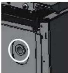
natural_image
Close-up of a mechanical component with a circular inset showing a hexagonal hole (no text or symbols visible)- Place the cooker as the image and adjust the legs through the appropriate adjustments (This must be done by two operators)
natural_image
3D rendering of a mechanical component with mounting feet and a side panel (no text or symbols visible)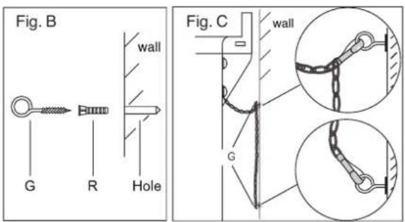
Stability bracket
WARNING: In order to prevent accidental tipping of the appliance, for example a child climbing onto the open oven door, the stabilising means must be installed.
Note: If the wall plug provided is not suitable for the wall material please use an appropriate device to ensure secure holding of the "screw" to the wall.
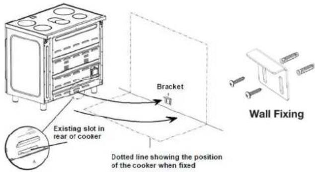
Note: refer to page 15 for installation on a plinth.
GAS CONNECTION
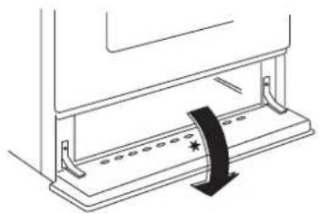
Gas installation must be made in accordance with AS5601; Also refer to rangehood manufacturers recommendation. Check gas pressure, note the correct setting from the data plate sealed inside the front appliance drawer *.
natural_image
Diagram of a mechanical device with a sliding mechanism and a black arrow indicating motion (no text or symbols)Installing the gas cooker:
(Flexible connection are NOT supplied with this appliance)
- An inlet manifold extension pipe must be fitted to the appliance. Part supplied in the drawer of the appliance.
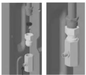
- Ensure that the pipe is connetted using the washer provided and that the braket is screwed to the appliance as shown in the diagram below.
- Fit the supplied pressure regulator (for Natural gas) using the NG test piont adaptor and washer to the inlet manifold. Ensure the arrow is pointing towards the appliance and that pressure testpoint is accessible from the final position.
- Push the cooker back and install the stabilizing chains.
- Connect the appliance inlet manifold to the consumer piping outlet using only fixed piping. This final connection is made when the product is pushed back into position by access under the cooker.
The hose assembly
- Must comply with AS/NZS 1869 Class B or D,
-
With 10 mm internal diameter and be kept as short as possible (less than 1,2 m)
-
It must not be kinked
- It must not be in contact with hot surfaces.
IT IS RECOMMENDED THAT A SERVICE TAP AND UNION BE FITTED ADJACENT TO THE APPLIANCE INLET TO FACILITATE FUTURE SERVICING.
5 burner models: set the burner pressure to 1kPa for Natural Gas and 2.75kPa for U-LPG with the wok burner operating a full rate'. For commissioning of the appliance with the regulator for Natural Gas, the test point pressure should be 1.00kPa with all burners operating on HIGH.
Apply a manometer to the test nipple and reset the regulator if necessary. Do not forget to replace the test nipple screw and to leave the instructions book with the user.
natural_image
Two grayscale images showing mechanical components with no visible text or symbols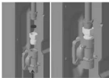
natural_image
Two grayscale industrial pipe fittings with a valve mechanism, shown from different angles (no text or symbols visible)Pressure tst point for ULPG
A test point fitting must be installed between the piping and the appliance for the pressure to be checked to ensure it is operating for ULPG at 2.75 kPa. Be aware that the appliance has two gas inlets (L/R). Before performing the leakage test select which side will be the connection point and cap and pressure test the side that will not be used.
Pressure regulator for natural gas
A test point fitting must be installed between the piping and the appliance for the pressure to be checked to ensure it is operating for NATURAL GAS at 1 kPa.
Be aware that the appliance has two gas inlets (L/R). Before performing the leakage test select which side will be the connection point and cap and pressure test the side that will not be used.
VERY IMPORTANT FOR THE INSTALLER
Do not attempt to turn or stress threaded elbow of the manifold: you risk damage to this part of the gas appliance which may void the manufacturers warranty.
Before Leaving – Check all connections for gas leaks. DO NOT use a naked flame for detecting leaks. Ignite all burners to ensure correct operation of gas valves, burners and ignition. Turn gas taps to low flame position and observe stability of the flame.
When satisfied with the cooker, please instruct the user on the correct method of operation.
In case the appliance fails to operate correctly after all checks have been carried out, refer to the authorised service provider in your area.
GAS CONVERSION AND ADJUSTMENT
When used with natural gas all burners have been preset at our factory and further adjustment should not be necessary. Conversion kits to other gases are available from the place of purchase. Do not attempt to fit the conversion kit yourself. Conversion to U-LPG gas should only be carried out by an authorized technician.
GAS ADJUSTEMENTS
- change the injectors
- adjust the minimum flow
'When conver ting from Natural Gas to U-LPG ensure that the NG regulator is removed and replaced with the Test Point Assembly. A gas regulator suitable for a supply pressure of 2.75kPa should be part of the gas tank supply and should be adjusted with the wok burner operating at maximum.
REPLACEMENT OF THE INJECTORS
When required to operate on other gas replace the injectors in accordance with information referred to in chart below.
TAB.1
| Gas Type | kPa | Jet mm ø | Burners | Power MJ/h |
| Natural | 1.00 | 1.20 | Semi-quick | 7.1 |
| 0.90 | Auxiliary | 4.0 | ||
| 1.50 | Quick | 11.0 | ||
| 1.63 | Triple Crown | 12.7 | ||
| U-LPG | 2.75 | 0.73 | Semi-quick | 7.1 |
| 0.53 | Auxiliary | 3.7 | ||
| 0.95 | Quick | 11.7 | ||
| 1.00 | Triple Crown | 13.0 | ||
| Regulator | NG Regulator | LP Test point adaptor | ||
Adjustments, conversions and gas installations must only be carried out by an authorised person.
After there placement of the injectors, replace also the label of the type of gas.
SPECIAL NOTE
After installation or any servicing operation, always ensure that the appliance is gas sound and that the components are now operating correctly. Items removed during servicing should be replaced in the reverse order to their removal.
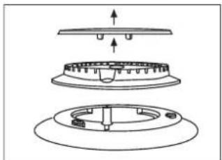
In order to change the work-top injectors, it is necessary to act as follows:
- remove the grids
- remove burners and flame-spreaders.
natural_image
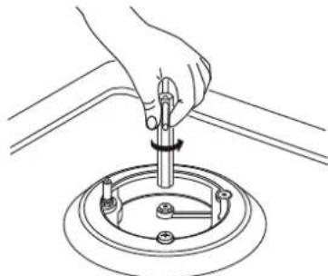
Technical diagram of a mechanical component with three views: top view, middle view, and bottom view (no text or symbols)- change the injector (see Fig. D) and replace it with another one suitable for the new type of gas (see tab. 1)
Fig. D
natural_image
Line drawing of a hand using a tool to adjust or install a mechanical component (no text or symbols present)MINIMUM FLOW ADJUSTMENT FOR HOB-TOPTAPS
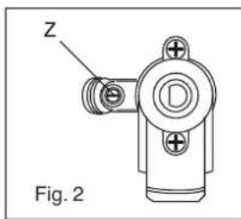
In order to adjust the minimum flame setting proceed as follows: switch the burner on, and set the knob at the minimum position ↑. Remove the knob from the tap.
The minimum adjusting screw «Z» is on the body of the gas tap (fig. 2).
natural_image
Technical line drawing of a mechanical component labeled 'Z' and marked as Fig. 2 (no text or symbols on the diagram itself)Unscrew the adjusting screw in order to increase the flow or screw it to decrease the flow.
The correct adjustment is obtained when the flame has a length of about 3 or 4 mm.
For butane/propane gas, the adjusting screw must be screwed in thigt.
Make sure that the flame does not go out turning quickly from the max. flow to the minimum flow .
Refit the knob again.
ELECTRICAL CONNECTION
The appliance must be installed by a suitably qualified person in accordance with these instructions and with the requirements of the Australian Wiring Rules AS/NZS 3000.
Fixed wired installations are to be provided with suitable isolation means in accordance with the said rules.
Any plug socket installed for the purpose of connecting the appliance to supply must be readily accessible when the appliance is installed.
Before making the connection, make sure that:
1) the safety circuit-breaker and the electrical system are able to withstand the load of the appliance (see nameplate).
2) the power supply system has an earth connection in good working order in accordance with the regulations in force;
IMPORTANT
The wires in the mains lead are coloured in accordance with the following code:
GREEN & YELLOW......EARTH
BLUE NEUTRAL
BROWN LIVE
Electric power 1,5 mm² core cable (15 amp. Fuse required)
Should conform to local authority requirements.
Also refer to rangehood manufacturers recommendations.
This appliance is supplied with a plug & cord, simply plug into a 3 pin household socket outlet witch is properly earthed.
If he supply cord is damaged, it must be replaced by an authorised service agent.
WARNING: THIS APPLIANCE MUST BE EARTHED.
The flexible mains lead and plug must not be in contact with hot surfaces.
2nd SECTION FOR THE USER
WARNING:
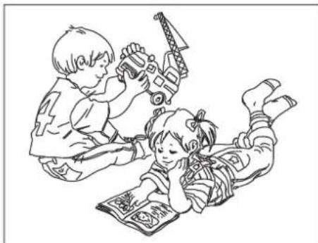
Children should be kept away while the oven or grill is in use since accessible parts become hot.
natural_image
Illustration of two children playing with toys, one lying on the floor and the other holding a hammer and eraser (no text or symbols)- WARNING -
During use, the appliance becomes hot.
Care should be taken to avoid touching heating elements inside the oven.
- Do not use oven base panel as a shelf, make use of the oven shelves.
-
To avoid splattering and smoke, position collecting tray under the grill with some water in it.
-
Always turn pan handles to the side or to the back of the hob. If they are left out into the room they can easily be hit or reached by children, this knocking the pan off the hob.
- Don't let children sit down or play with the oven door. Do not use the drop down door as a stool to reach above cabinets.
- Once your cooking is over make sure to close the main gas supply.
WARNING
* This appliance is not intended for use by young children or infirm persons without supervision.
* Young children should be supervised to ensure that they do not play with the appliance.
- WARNING -
In order to prevent accidental tipping of the appliance, for example by a child climbing onto the open oven door, the stabilizing means must be installed.
- 1 Minute Tour -
Be safe
Please read the rest of the instruction book which contains important information to help you use the appliance safely and efficiently.
Gas and Electricity on
Make sure that the gas supply is turned on and that the appliance is plugged in and switched on. The ignitor needs electricity.
In case there is no electric current, the burner can also be lighted using a match.
It is recommended that pans suitable to the size of the burner should be used as follows:
| BURNERS | PANS | |
| fl min. | fl max | |
| AUXILIARY | 80 mm | 160 mm |
| SEMI-RAPID | 120 mm | 200 mm |
| RAPIDE | 200 mm | 230 mm |
| TRIPLE CROWN | 230 mm | 260 mm |
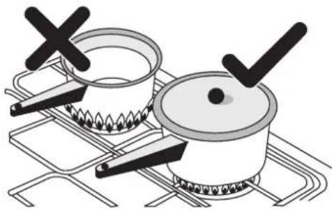
Always use pans with a flat base diameter, which are well balanced and stable in use, a pan which overhangs the hotplate should not be used. Avoid using old, misshapen pans, or pans which are unstable when placed on a flat surface. Do not use "split pans" as they are inherently unstable.
To save gas, always position pans centrally over the burners and adjust the flames so that they do not lick up the sides of the pan and only the base is heated. Always put lids on saucepans and boil only the amount of liquid you use. When the liquid has boiled adjust the setting to maintain a simmer. Do not light the burner until the pan is in position and turn off the burner before removing the pan. In hard water areas, descale kettles regularly. For safety, keep saucepan handles turned to a safe position so they are out of reach of small children and cannot be accidentally knocked.
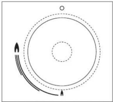
To tunr the burner OFF, turn the control knob clockwise to the OFF setting (marked with a dot ☐)
Automatic electric ignition
To turn on a burner, press the knob corresponding to the selected burner and turn it anticlockwise to the maximum position. Keeping the knob pressed, the electric automatic ignition of the burner will be started up. In case there is not electric current, the burner can also be lighted using a match.
natural_image
Diagram showing concentric circles with arrows indicating direction, no text or symbols presentThe small flame indicates the 'low position'.
Turn the knob to it after the contents of a pan have boiled.
natural_image
Illustration of two cooking pots on a stove with steam rising (no text or symbols)The smaller burners are for smaller pans and simmering. Make sure flames are under the pans. Using a lid will help the contents boil more quickly.
WARNING
It is not recommended to press push button for ignition if all the burners are not located in the proper positions. The burner heads, burner skirts and pan supports are removable for better cleaning: Always ensure that the burner skirts and heads are replaced correctly so that the burners function safely and correctly.
During the use of the appliance pay attention that water or any liquid does not enter into the appliance through the holes of the burners or around the rods of the valves or the push button electronic lighter.
Water or juice will produce dangerous short-circuits and can seriously damage the working of the Hotplate.
HOW TO USE YOUR ELECTRIC OVEN
- Before cooking in the first time we recommend that the oven should be operated at 200°C for 30 minutes to remove any manufacturing greases and odours.
- Do not place items or pan directly on to the oven bottom.
- Foil should only be used to cover food and not oven shelves or party of the oven. When used improperly will obstruct the air circulation causing problems in cooking and/or harmful accidents.
MULTIFUNCTIONAL OVEN
The oven is fitted with:
- a lower heating element;
- an upper heating element;
- a circular heating element surrounding the fan.
N.B.: Always set the temperature on the thermostat knob before selecting any of the functions.
Oven thermostat knob
To obtain an oven temperature between 60^ C and MAX ^ C, turn the knob clockwise.
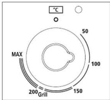
Oven commutator knob
Depending on the type of oven, it is possible to select one of the following functions turning the commutator knob clockwise.
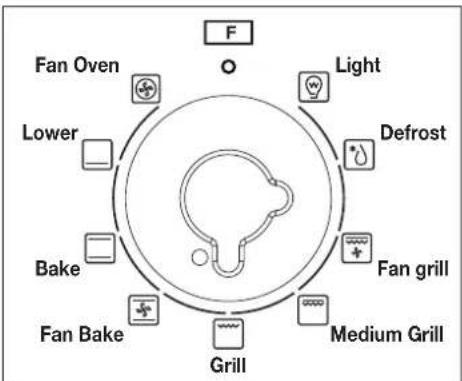
Note:
All the functions mentioned above switch the oven internal light on. A warning light on the control panel will stay lit until the temperature is reached; after it will light up intermittently. Always use the oven with the oven door closed.
Use of the oven
Note: ovens with separate thermostat and commutator.
When the functions Grill and Fun Grill are used, place the thermostat knob between 180 ÷ 200^ as maximum temperature.
ATTENTION:
The temperature shown on the control panel corresponds to the temperature in the oven centre only when the functions selected are Bake or Fan Oven.

Light
When you turn the control knob to this position, the light will be on for all the following operations.

Defrost
The air at ambient temperature is distributed inside the oven for defrosting food very quickly and without proteins adulterations.

Conventional cooking
Top and bottom heating elements are used together. Preheat the oven for about ten minutes.
This method is ideal for all traditional roasting and baking. For sealing red meats, roast beef, leg of lamb game, bread, foil-wrapped food (papillotes), flaky pastry. Mid shield position recommended.

Fan assiste multilevel oven
Cooking of similar or different foods placed on different shelves (up to 2 levels at a time).

Fan cooking
Both top and bottom heating elements are used and the fan circulates the air inside the oven. Recommended for poultry, pastries, fishand vegetables. Heat penetrates the food better and both the cooking and preheating times are reduced. Different foods can be cooked at the same time in one or more positions. This function provides even heat distribution and does not mix the smells. Allow about ten minutes extra when cooking foods at the same time.

Lower element
Using the lower element. Ideal for cooking all pastry based dishes. This allows you to cook dry tart pastry without over cooking the fruit filling. Use this for flans, quiches, tarts, pâté and any cooking that needs more heat and radiation from below.


Grill
Caution: In this function the temperature control knob must be set from 50°C to Grill position. Using the top level element. Five minutes preheating is required to get the element hot. Use the grill when the door is closed.

Fan assisted grilling
Caution: In this function the temperature control knob must be set from 50°C to Gril position. The top heating element is used in conjunction with the fan circulating the air inside the oven. Ideal for cooking thicke food stuffs, whole pieces of meat such as roast pork, poultry, etc. Preheating is necessary for red meats but not for white meats. Place the foof to be grilled directly on the shelf centrally, at the middle level. Slide the driptray under the shelf to collect the juices. Make sure that the food is not too close to the grill. Turn the food over halfway through cooking.

Rotisserie (in option)


The top heating element is used in conjunction with the rotisserie providing the real flavour of a traditional roast.
GENERAL INSTRUCTION
Warning: remember ovens get hot; some parts naturally become very hot, notably the glass oven door and the protective strip. Keep children away from oven at all times and warn them about the danger.
GUIDE FOR CONVENTIONAL COOKING (Bake)
(Outer ring of upper electric element and lower electric element ON) The following Cooking Guides give the recommended shelf positions (counted from the bottom), thermostat settings and approximate cooking times for a range of baked items, using the conventional oven, using one tray only. Cooking results are a matter of personal preference and may easily be adjusted to suit individual requirements by slight adjustment of the temperature and or cooking time.
Preheating of the oven is recommended for 10-15 minutes or until the oven thermostat indicator light switches off to show the selected temperature has been reached.
When using a baking tray it should be placed centrally on the oven shelf with the short sides of the tray parallel to the sides of the oven. Do not use trays, tins or dishes larger than 380 mm (15") long, 356 mm (14") wide, as cooking results may be impaired.
| Food | Thermostat setting °C | Shelf Position (Counted from Bottom) | Cooking Time |
| Small cakes (12 on tray) | 195 | 3 | 20 - 30 mins. |
| Victoria sandwich (2x7"/180mm) | 190 | 3 | 25 - 35 mins. |
| Swiss roll or whisked sponge | 200 | 3 | 20 - 25 mins. |
| Fruit cake (8"/205mm) | 155 | 2 | 2 - 3 hours. |
| Scones | 260 | 3 | 10 - 20 mins. |
| Meringues | 95 | 2 | 2 - 3 hours. |
| Shortcrust Pastry | 210 | 3 | 25 - 45 mins. depending |
| Puff or Flaky Pastry | 220 | 2 | 20 - 35 mins. upon |
| Choux Pastry | 220 | 3 | 25 - 35 mins. dish |
| Biscuits | 200/220 | 3 | 15 - 25 mins. depending upon type |
| Bread | 250 | 2 | 30 - 40 mins. |
| Milk pudding | 165 | 2 | 1 H - 2 hours. |
| Pizza | 270 | 3 | 25 mins. |
| Lasagne | 170 | 3 | 75 mins. |
| Oven noodles | 160 | 3 | 75 mins. |
| BEEF on bone & crusty (rare) | 270 rare | 3 | 12 mins. per 1/b (500 g) plus 12 mins. |
| 220 °C | 3 | 15 mins. per 1/b (500 g) plus 15 mins. | |
| (medium) | 220 °C | 3 | 20 mins. per 1/b (500 g) plus 20 mins. |
| (well done) | 180 °C | 3 | 25 mins. per 1/b (500 g) plus 15 mins. |
| LAMB on bone | 220 °C | 3 | 20 mins. per 1/b (500 g) plus 20 mins. |
| 170 °C | 3 | 27 mins. per 1/b (500 g) plus 27 mins. | |
| Boned and rolled | 220 °C | 3 | 25 mins. per 1/b (500 g) plus 25 mins. |
| 170 °C | 3 | 35 mins. per 1/b (500 g) plus 20 mins. | |
| PORK on bone | 220 °C | 3 | 25 mins. per 1/b (500 g) plus 25 mins. |
| Boned and roller | 180 °C | 3 | 30-35 mins. per 1/b (500 g) plus 35 mins. |
| VEAL on bone | 220 °C | 3 | 25 mins. per 1/b (500 g) plus 25 mins. |
| Boned and roller | 220 °C | 3 | 30 mins. per 1/b (500 g) plus 30 mins. |
| CHICKEN | 220 °C | 3 | 20 mins. per 1/b (500 g) plus 20 mins. |
| 170 °C | 3 | 25 mins. per 1/b (500 g) plus 25 mins. | |
| TURKEY | 220 °C | 3 | 20 mins. per 1/b (500 g) |
| 170 °C | 3 | 25 mins. per 1/b (500 g) | |
| DUCK | 220 °C | 3 | 20 mins. per 1/b (500 g) |
| 170 °C | 3 | 25 mins. per 1/b (500 g) | |
| GOOSE | 220 °C | 3 | 20 mins. per 1/b (500 g) plus 20 |
PLATE WARMING
Ovenproof plates and dishes may be warmed in the oven on a low temperature setting. Remember do not place items directly into the oven base.
Warning: do not use foil to cover the oven shelves, or any part of the oven interior including the oven base. Foil should only be used to cover food and cooking dishes. Always place items which may boil over (e.g. fruit pies) on a baking tray to prevent spillage burning onto the oven base. Foil used improperly is frequent cause of oven problems and painful accidents. Avoid letting grease deposit collect around the upper heating element: it will cause smoking and may start a fire. Remember do not place pan or items directly onto the oven base. Never leave unit unattended at hight heat settings. Boil over causes smoking and greasy spill over that may start a fire. If a grease fire should occur in a pan put out the flame by placing a lid on the pan. Do not throw water on a grease fire.
GUIDE FOR FORCED CONVECTION COOKING
(Back rolled electric element with fan)
The accessories provided with the oven can be slotted in at 5 positions: the following guide concerns cooking times and thermostat settings using N. 2 shelves on the same time (in position N. 2 and N. 4). Cooked results are a matter of personal preference and may easily be adjusted to suit individual requirements by slight adjustment of the temperature and/or cooking time, or when using more or less shelves in the same time. Preheating of the oven is recommended for 10-15 minutes or until the oven thermostat indicator light switches off to show the selected temperature has been reached.
When using a baking tray it should be placed centrally on the oven shelf with the short sides of the tray parallel to the sides of the oven. Do not use trays, tins or dishes larger than 380mm (15") long, 356 mm (14") wide, as cooking results may be impaired.
| Food | Thermostat setting °C | Cooking Time |
| Small cakes (12 on tray) | 175 | 15-25 mins. |
| Victoria sandwich(2x7"/180mm) | 170 | 20-30 mins. |
| Swiss roll or whisked sponge | 180 | 15-20 mins. |
| Fruit cake (8"/205mm) | 135 | 1 H - 2 H hours. |
| Scones | 210 | 8-15 mins. |
| Meringues | 80 | 1 H - 2 H hours. |
| Shortcrust Pastry | 190 | 20-40 mins. depending |
| Puff or Flaky Pastry | 200 | 15-30 mins. upon |
| Choux Pastry | 200 | 20-30 mins. dish |
| Biscuits | 170/180 | 10-20 mins. depending upon type |
| Bread | 200/220 | 25-35 mins. |
| Milk pudding | 150 | 1 H - 2 hours. |
| Pizza | 250 | 20 mins. |
| Lasagne | 165 | 60 mins. |
| Oven noodles | 150 | 60 mins. |
| BEEF on bone | 230 rare & crusty | 9 mins. per 1/b (500 g) plus 9 mins. |
| BEEF on bone | 190 °C (rare) | 15 mins. per 1/b (500 g) plus 8 mins. |
| 190 °C (medium) | 20 mins. per 1/b (500 g) plus 10 mins. | |
| 160 °C (well done) | 25 mins. per 1/b (500 g) plus 8 mins. | |
| Boned and rolled | 190 °C (rare) | 20 mins. per 1/b (500 g) plus 10 mins. |
| 190 °C (medium) | 25 mins. per 1/b (500 g) plus 15 mins. | |
| 160 °C (well done) | 30 mins. per 1/b (500 g) plus 8 mins. | |
| LAMB on bone | 190 °C | 20 mins. per 1/b (500 g) plus 10 mins. |
| 155 °C | 27 mins. per 1/b (500 g) plus 14 mins. | |
| Boned and rolled | 190 °C | 25 mins. per 1/b (500 g) plus 14 mins. |
| 155 °C | 25 mins. per 1/b (500 g) plus 14 mins. | |
| PORK on bone | 200 °C | 25 mins. per 1/b (500 g) plus 14 mins. |
| Boned and roller | 160 °C | 30-35 mins. per 1/b (500 g) plus 18 mins. |
| VEAL on bone | 200 °C | 25 mins. per 1/b (500 g) plus 14 mins. |
| Boned and roller | 200 °C | 30 mins. per 1/b (500 g) plus 14 mins. |
| CHICKEN | 200 °C | 20 mins. per 1/b (500 g) plus 10 mins. |
| 155 °C | 25 mins. per 1/b (500 g) plus 13 mins. | |
| TURKEY | 200 °C | 18 mins. per 1/b (500 g) plus 14 mins. |
| 155 °C | 23 mins. per 1/b (500 g) | |
| DUCK | 200 °C | 18 mins. per 1/b (500 g) |
| 155 °C | 23 mins. per 1/b (500 g) | |
| GOOSE | 180 °C | 18 mins. per 1/b (500 g) plus 20 mins. |
USING THE GRILL
The grill is situated in the top of the oven compartment. The grill pan should be located on the top oven shelf position. Always grill with the door closed.
Warning:
Do not place fatty foods too close to the grill and never leave the grill unattended. If fatty foods are grilled, or roasting has been cooked in the oven at a high temperature the grill element may smoke. This is not dangerous and the smoke is caused by the fat burning off when the grill element is hot. Leave the grill element on until the smoking has stopped t-hen use as normal. If a grease fire should occur in a pan put out the flame by placing a lid on the pan. Do not throw water on a grease fire.
INSTRUCTION FOR USE OF CONTROL DEVICES (Depending on model)
Using the programmer of cooking
Main functions (for some models)
1 Time function, keep the time in 24 hours.
2 Make an reservation for the oven work time, and can set anytime in 24 hours.
3 Set the oven work time, the longest maybe 10 hours.
Operation Panel and Instructions (for some models)
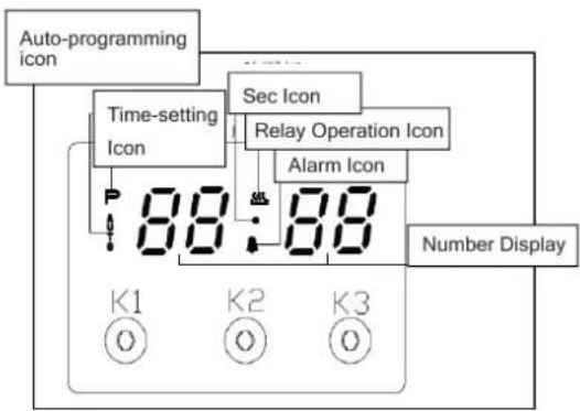
flowchart
graph TD
    A["Auto-programming icon"] --> B["Time-setting Icon"]
    B --> C["88"]
    D["Sec Icon"] --> E["Relay Operation Icon"]
    E --> F["Alarm Icon"]
    F --> G["88"]
    H["Number Display"] --> I["K1 O"]
    H --> J["K2 O"]
    H --> K["K3 O"]
1 List of functions
Instructions from left to right: Key1, Key2, Key3.
Key1 Decrease Key
Key2 Mode Key
Key3 Increase Key
Note: Press Key 1 and Key 3 under the setting mode, which nchanges the time by one minute either up or down. If keep pressing them, the number will be up or down quickly.
2 Icon Instructions
"Auto-programming icon": it will flash when setting automatic program and the end of automatic program. If automatic program has been set, after 5s, it will keep lighting up. At the end of automatic program, the flash will be off when resetting the clock or it will keep lighting up when resetting automatic program after 5s.
"Time-setting Icon" will flash when setting Beijing time.
"Sec Icon" and "Alarm Icon" are flashing under the mode of time setting and alarm setting, after 5s of setting, it will turn to lighting up.
"Relay Operation Icon"b shows the working state of relays. The icon will keep lighting up if contact are connected, and will be off if contacts are disconnected. "Number Display" is LED Nixie Tube.
Control Function and Intructions
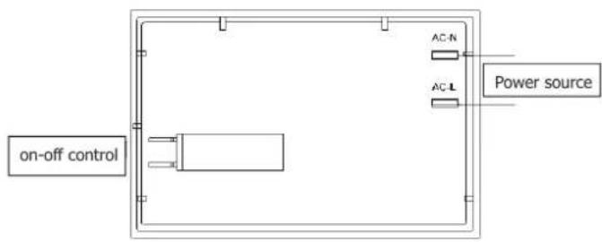
As shown in the picture, on-off control is used to control heating components of oven, the left is power source which can be connected under the 220V.
1 Time Adjustment after Starting up
When the power is on, it shows 12:00 and flashes. The relay contact is disconnected, auto-programming icon keeps lighting up, time setting icon flashes.
Press K1 or K3 to the time or press K2 to get into the present working mode. The relay contact is connected.
Press K2 by 4 times to get into the present time-setting mode under the common mode.
2 Alarm and Buzz Function
Press K2 once under the common mode: "Alarm Icon" flashes."
Press K1 or K3 to adjust the present alarm clock.
5s after adjusting to the time you need, "Alarm Icon" keeps flashing, and will work after setting up. In this case, pressing K1 can know the alarming time( it will show seconds at one ast minute).
When alarm counts down to zero, alarming program ends, alarm icon flashes, and the buzzer os buzzing. Press any key to stop the buzzing or it will turn off automatically after 2 minutes.
3 Auto-programming Setting and Instructions
① Semiautomatic program mode
Use this setting for oven working time, automatic heating switch-off at the end of setting time, buzzer will inform the user.
Press K2 twice or three times to get into the auto-programming time setting, "Auto-programming Icon" flashes. Press K1 and K3 to ajust continuous time and end time.
5s after setting, it will work automatically, "Auto-programming Icon" keeps lighting up. If continuous time is 0, turn off the relay contact, and "Relay Operation Icon" is dark, "Autoprogramming Icon" flashes, the buzzer is buzzing.
This mode's range of continuous time and end time:
Adjustment range for continuous time: >0 but <10 hours
Adjustment range for end time: present time < end time <= present time + 10 hours.
If meet this standard: end time = present time + continuous time.
For example: the present time is 2:00, then the max. end time is adjusted to 12:00 (2:00 10 00 12 00). When the end time is adjusted to 12:00, then the continuous time is 10:00.
5s after adjusted, automatic program is working.
After 10 hours, if continuous time is counting down to 0, turn off the relay contact, and "Relay Operation Icon" is dark, "Auto-programming Icon" flashes, the buzzer is buzzing.
Note:
- only use this setting for either continuous time or end time. For example: the present time is 2:00, and if let the oven work for 3 hours, set the continuous time to 3:00, and the end time will automatically change to 5:00 and vice versa.
- If the continuous time is equal to 0 or the end time is equal to the present time, it means that the automatic program is over.
- When the automatic program is over, the continuous time is 0 and the end time is equal to the present time.
② Automatic Mode
Use this mode for setting oven's starting time and end time, which means make an appointment to boot. When the time is
over, it will automatically turn off the heating and the buzzer is buzzing to inform the user.
Press twice to get into the continuous time setting mode under the common mode, press three times to get into the end time.
When the continuous time setting is ok or the end time setting is ok, then press K2 to get into the other kind of automatic program time setting, "Auto-programming Icon" flashes, press K1 and K3 to ad just continuous time and end time setting mode.
5s after automatic program setting, it will automatically work, and "Auto-programming Icon" keeps lighting up. Turn off the relay contact, and the icon is dark. When work until the starting time, the relay contact is connected, the icon is light. When the continuous time is counting down, if the continuous time is 0, turn off the relay contact, "Relay Operation Icon" is dark, "Auto-programming Icon" flashes, and the buzzer is buzzing.
The continuous time and the end time under this model will be set as follow: Starting time = end time - continuous time
For example, the present time is 2:00, set the continuous time to 3:00, and the end time to 10:00, then the starting time is 7:00 (7:00 10:00 3:00). The relay contact is connected and its icon is light. After working for continuous 3 hours, the continuous time is 0, turn off the relay contact, "Relay Operation Icon" is dark, "Auto-programming Icon" flashes, the buzzer is buzzing.
Note:
1 End time > present time + continuous time, < but 23 hours and 59 minutes
For example: the present time is 2:00, continuous time is 0:01, then the range for end time is 2:02 (2:02 2:00+1).
2 Continuous time > 1 minute, continuous time and end time both will be set.
3 If the continuous time is equal to 0 or the end time is equal to the present time it meas the automatic program is over.
4 When the automatic program is over, the continuous time is 0, and the end time is the same with the present time.
4 Cancel Function
When semiautomatic or automatic function is starting, press K1 and K3 at the same time which can cancel the automatic mode. (to cancel continuous time and end time).
Control knob for minute minder (for same models)
The minute minder is a countdown timer which emits an audible signal when the cooking time has elapsed.
The minute minder runs independently of the oven.
Use this control knob to set the cooking time.
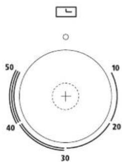
| Setting | Meaning |
| O | Off |
| 1 - 50 | Cooking time in minutes |
Accessories
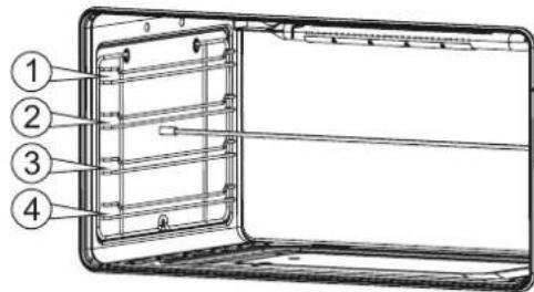
The accessories can be inserted in the oven in 4 different shelf positions.
You can pull the accessories two-thirds of the way out without them tipping. This allows meals to be removed easily.
You can buy accessories from the after-sales service or from specialist retailers.
| Accessory | Description |
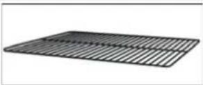 | Baking and roasting shelfFor ovenware, cake tins,roasts, grilling and frozenmeals. |
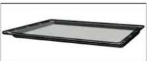 | Enamelled baking trayFor moist cakes, pastries,frozen meals and largeroasts. Can also beinserted underneath thewire rack or rotary spit andused as a drip tray tocollect fat. |
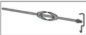 | Rotary spitFor roasts and large piecesof poultry. Use only incombination with theenamelled baking tray. |
USE OF THE ELECTRIC GRILL
USING THE GRILL
Turn the oven knob to the right and place it on the grill position. The grill pan should be located on the top oven shelf position. Always preheat the grill on full for 3-5 minutes before inserting the food.
The user can change the shelves, depending on his personal whishes and on the different food.
To remove the shelves from the oven, pull them forward you, tilt front end upward and pull them out.
To replace it in the opposite manner as before.
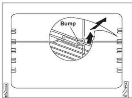
Install shelves by locating them in the horizontal guide rails on the oven walls. The raised portion of the shelf is to be facing the rear wall of the oven.
Using the rotary spit
The rotary spit can be used to cook joints such as rolled joints and poultry with excellent results. The meat is roasted thoroughly and evenly.
Use the rotary spit in conjunction with the grill.
Preparing joints
Place the joint as centrally as possible on the rotary spit and secure it at both ends with the retaining clips.
You can also truss the joint with string. With poultry, bind the ends of the wings underneath the back and the thighs against the body. This will prevent them from becoming too dark.
Pierce the skin on the underside of the wings to allow the fat to escape.
Inserting the rotary spit
Insert the rotary spit as follows:
- Hook the spit holder into the bracket on the ceiling of the cooking compartment.
If you require to preheat the oven, hook in the holder before preheating.
Risk of burns
Never touch the hot surfaces of the cooking compartment or the heating elements.
Children must be kept at a safe distance from the appliance at all times.
Open the appliance door carefully. Hot steam may escape.
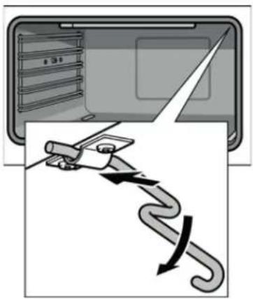
natural_image
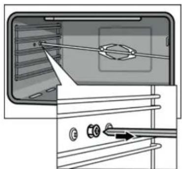
Diagram showing a device with a curved arrow indicating motion or force, next to an open panel (no text or symbols present)- If the oven has been preheated, only attach the rotary spit if you are using an oven cloth or wearing (thermal) oven gloves. To attach the spit, slide one end into the recessed adapter in the left-hand side panel of the cooking compartment.
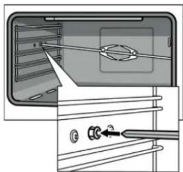
natural_image
Diagram showing a device with a tool interacting with a screen and a close-up of its screen (no text or symbols visible)- Hook the other end into the holder.
- Pour a little bit of water into the baking tray and slide this into shelf position 1 to collect the run-off fat.
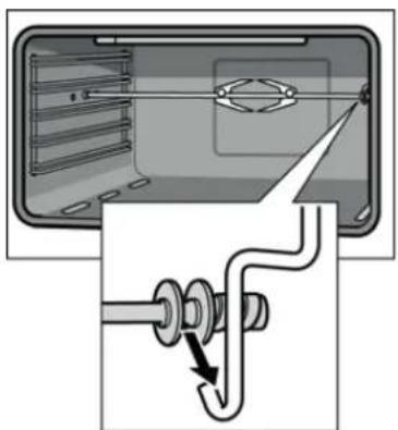
natural_image
Diagram showing a mechanical assembly with a pipe and connector, no text or symbols presentRemoving the rotary spit
Risk of burns.
Never touch the hot surfaces of the cooking compartment or the heating elements.
Children must be kept at a safe distance from the appliance at all times.
Open the appliance door carefully. Hot steam may escape.
Risk of burns.
Never touch the rotary spit or other accessories directly when they are hot.
Always wear oven gloves or heat-resistant gloves when handling hot accessories.
Remove the rotary spit as follows:
- Carefully open the appliance door. Carefully remove the rotary spit from the holder.
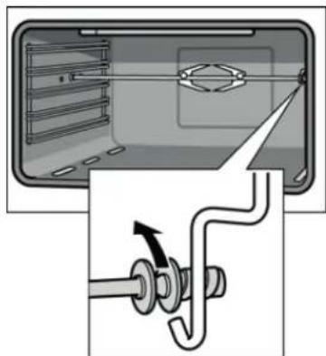
natural_image
Diagram showing a mechanical assembly with a pipe and lever mechanism (no text or symbols)- Carefully withdraw the rotary spit from the recessed adapter in the side panel and remove it rom the oven.
- Take out the baking tray.
natural_image
Diagram showing a device interior with a tool interacting with a screen and a separate view of a device with arrows indicating direction (no text or symbols present)CLEANING
Before cleaning the appliance, close the gas stopcock and unplug appliance or disconnect power at the main circuit breaker of the electrical system.
Do not clean the appliance surfaces when still hot.
Always clean off spillage as quickly as possible to prevent burning on which will make removal more difficult. Wash with a clean cloth soaked in hot soapy water, rinse and dry with a soft cloth.
DO NOT USE ABRASIVES. CAUSTIC PASTES OR SPRAYS. COARSE CLEANING PADS OR POWDERS. DO NOT USE EXCESSIVE WATER WHEN CLEANING YOUR OVEN IN ORDER TO AVOID WATER PRESSING THROUGH CLEFTS INTO THE BACK OF CONTROLS PANEL OR OF THE UNIT.
NOTE: A steam cleaner is not to be used for cleaning this appliance.
Pan supports and burners
The burner heads can be removed for cleaning.
NB Do not drop hot burner caps in cold water.
Because of the rapid cooling they might get damaged.
Lift off and soak for about 10 minutes in hot water with a little detergent. After having cleaned and washed them, dry them carefully.
Make sure that no burner holes are clogged.
Clean the burners once a week or more frequently if necessary.
Make sure you have reassembled the burners correctly.
Pan supports can be washed by hand or in a dishwasher.
Remember to remove rubber feet (if fitted) prior to washing.
Refit them afterwards.
Do not use harsh abrasive cleaners or sharp metal scrapers to clean the oven door glass since they can scratch the surface, which may result in shattering of the glass.
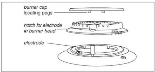
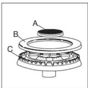
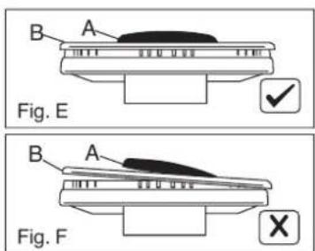
For a triple crown burner, make sure head "C" and covers "A" and "B" are properly placed on their seats as figure E and not off-centered as in figure F
Daily
Regular wiping down directly after use prevents dirt from burning on. Clean the appliance with water and a detergent or all purpose cleaner.
Avoid using too much water to prevent it entering the burner or ventilation openings.
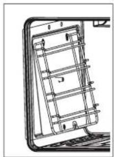
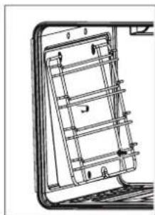
You can remove the hook-in racks in order to clean them separately.
The hook-in racks are all fixed to the walls of the cooking compartment at four points.
To remove the hook-in racks, proceed as follows: (Fig. G)
-
Undo the screw on the bottom the hooking rack. The lower hooks of the hook-in rack are released.
-
Take hold of the top of the hook-in rack and screw. On the screw on the bottom the hook-in rack again.
To reinsert the hook-in racks, proceed as follows: (Fig. H)
- Insert the upper hooks into the drill holes in the side panel.
- Pull the hook-in rack slightly downwards and insert the lower hooks into the drill holes.
Removing the hook-in racks
Inserting the hook-in rack
natural_image
Technical line drawing of a mechanical component with internal grid structure (no text or symbols)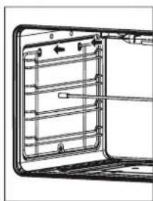
natural_image
Diagram of a refrigerator interior showing internal compartments and door handle (no text or labels)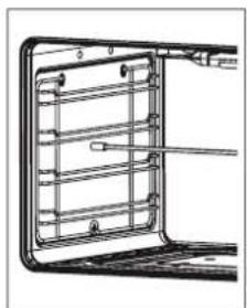
natural_image
Technical line drawing of a door frame with internal compartments and handlebars (no text or symbols)Fig. G
natural_image
Technical line drawing of a mechanical component with internal grid structure (no text or symbols)Fig. H
Oven accessories (shelves, trays etc) should be washed in mild detergent solution and should not be treated with abrasives. The oven interior panels should be cleaned with mild detergent solution, mild cream cleaners or a moist soap pad.
Install shelves by locating them in the horizontal guide rails on the oven walls.
The raised portion of the shelf is to be facing the rear wall of the oven.
IMPORTANT
Do not use excessive water when cleaning the oven and avoid water passing through the fan grill or ducts in the oven back. Avoid letting grease deposit collect around the upper heating element: it will cause smoking and may start a fire.
Cleaning the interior glass of the oven
The interior glass of the oven door can be removed: with the door in the semi-open position, use both hands to remove the glass.
After cleaning, refit the glass by proceeding in reverse order.
Note:
In some models, the glass is screenprinted. In this case, when refitting the glass make sure the screenprinted part is legible when the oven door is opened.
The interior glass of the oven
The interior glass of the oven door can be removed:
1 open the oven door completely.
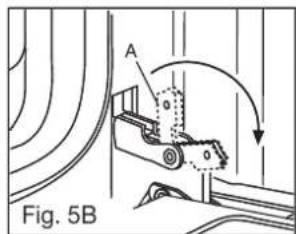
2 flip the hinge hooks "A" outwards (see fig. 5B).
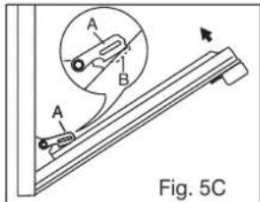
3 shut the oven door slowly until it reaches hooks "A", making sure these are locked into slots "B" of the oven door, as shown in fig. 5C.
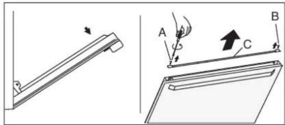
4 with the door in a semi-open position, remove the screws A and B and the profile C as shown in fig. 4.
5 use both hands to remove the glass as shown in figures 4.
6 after cleaning, refit the glass by proceeding in reverse order.
Fig. 4
natural_image
Technical diagram showing a lever mechanism and a slide with labeled points A, B, C (no text or symbols present)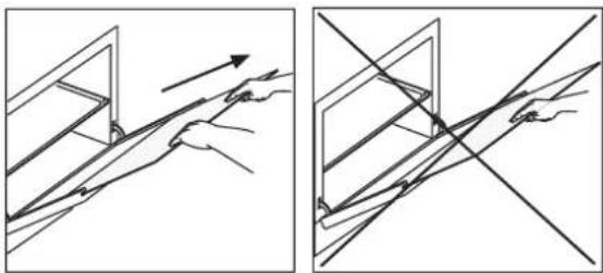
natural_image
Two diagrams showing hand positioning and diagonal line crossing (no text or symbols)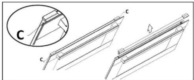
natural_image
Technical line drawing of a mechanical assembly with three views (c, c', and an inset showing a detail labeled 'C') without any text or symbols.The inner glass of the oven with fixing snap (only for the models where is provided)
The inner glass of the oven door can be removed:
1 open the oven door completely.
2 flip the hinge hooks "A" outwards (see fig. 5B).
3 shut the oven door slowly until it reaches hooks "A", making sure that hinges are locked into slots "B" of the oven door, as shown in fig. 5C.
4 with the door in a semi-open position, press the two buttons C on the upper profile, and extract the profile as shown in fig. 4
5 use both hands to remove the glass as shown in figures 4.
6 after cleaning, refit the glass by proceeding in reverse order.
Removal of oven door
In-depth cleaning of the oven becomes more convenient if the door is removed following the instructions below:
open the oven door completely.
2 flip the hinge hooks "A" outwards (see fig. 5B).
3 shut the oven door slowly until it reaches hooks "A", making sure these are locked into slots "B" of the oven door, as shown in fig. 5C. Remove the glass Fig. 5A (only for models where present).
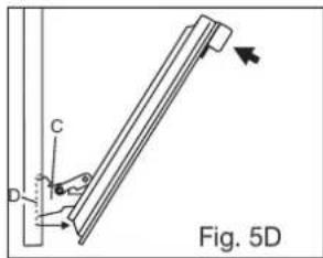
4 Using both hands, push the oven door lightly inwards, to enable the door hinges "C" to come away from the slots "D" (see fig. 5D) and pull the door towards you until it is released from the oven.
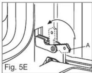
After cleaning it, reposition it correctly following the abovesteps in the reverse order and flipping hooks "A" inwardsbefore you shut the oven door (fig. 5E).
CAUTION:
Do not use rough or abrasive materials or sharp metal scrapers to clean the glass doors of the oven since they may scratch the surface and cause the glass to break.
WARNINGS
Before performing any repair or operation, switch the appliance off and close the gas tap.
The manufacturer declines all responsibility for any damage to persons, animals or things caused by failure to observe the rules indicated above. In case it is necessary to repair or replace the inside components, act as follows:
WARNINGS
Isolate the cooker from the electricity supply before attempting to replace the oven lamp.
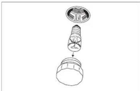
The oven lamp used is of a special type withstanding high temperatures. To replace it, act as follows: disassemble the protecting glass (A) and replace the burnt lamp with one of the same type. Reassemble the protecting glass.
natural_image
Diagram of a light bulb assembly showing internal components and an end cap (no text or labels)OPTIONAL: ONLY FOR THE MODELS EQUIPPED WITH TELESCOPIC RAILS
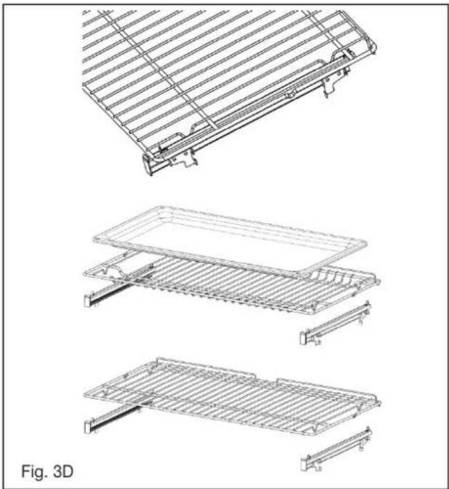
The oven is equipped with telescopic rails to position the pan and wire grid (Fig. 3d).
You can change the position, depending on your personal taste and needs of different foods (Fig. 3e).
natural_image
Technical line drawings of a grid-like mechanical component, showing three views from top to bottom (no text or symbols)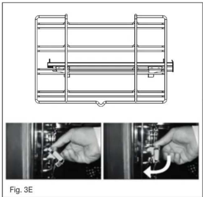
natural_image
Technical line drawing of a mechanical assembly with two views showing hand positioning and a rotation arrow (no text or symbols)Disassembly of the worktop must only be done by a qualified service technician.
DISASSEMBLE OF WORK-TOP
In case it is necessary to repair or replace the inside components, act as follows:
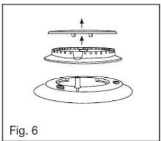
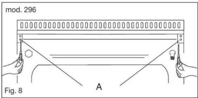
Remove the grids, remove burners and flame-spreaders (see fig. 6), unscrew the visible screws "V" placed on the work-top (see fig. 7). Disassemble the work-top by unscrewing the rear screws "A" (see fig. 8 according to the models). In this way it is possible to lift the work-top and to reach the inside components.
natural_image
Technical diagram of a mechanical assembly with three views (top, front, side) showing internal components and alignment arrows, labeled Fig. 6 (no text or symbols on the diagram itself)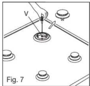
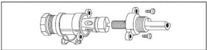
GREASING OF TAPS
If a tap becomes hard to be turned, grease it using a specific grease withstanding high temperatures. Act as follows: open the work-top and disassemble also the control panel as described on the previous paragraph. Unscrew the two fixing screws from the burner body (see picture) and remove the cone.
natural_image
Technical line drawing of a mechanical assembly showing two views of a cylindrical component with threaded ends and mounting holes (no text or symbols)TAPS REPLACEMENT
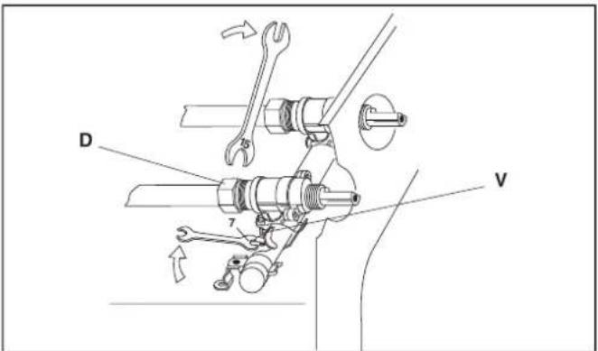
Act as follows: open the work-top and disassemble also the control panel as described on the previous paragraph. Unscrew screw nut D of the gas tube supplying the burner. Unscrew screw V fixing the tap to the bridle and remove it (see picture).
Note: Every time the tap is replaced, it is necessary to replace the seal gasket too check the connection seal by means of soapy water.
Clean the cone and its slot by means of a cloth soaked with solvent. Slightly grease the cone with the relevant grease, put it in its slot, and turn it some times. Remove the cone again, remove the excess grease making sure the gas entries are not obstructed by grease residue. Assemble everything carefully in the opposite direction check the connection seal by means of soapy water.
SOME SAFETY POINT
Do not use the appliance as a space heater.
If you smell gas
Open a window. Do not use any electrical switches. Immediately extinguish naked flames. Isolate appliance from gas mains supplies via the isolation stopcock. Contact local gas authority or emergency services as appropriate. In the event of food fire. Isolate appliance from electric / gas mains supplies if safe to do so. Try to extinguish flames with the appropriate equipment (fire blanket or extinguishing foam). Do not use water on cooking fat / oil fires.
If in difficulty call emergency services.
- Do not store or use flammable products or aerosol containers near the hotplate or burners.
- Never flambe, under an extractor - even if the ventilator is switched off.
The high flames can cause fire.
For your safety and that of your children
- Do not store items that are attractive to children above or near the appliance.
- Keep children well away from the appliance: do not forget that some parts of the appliance or of the pans become very hot and dangerous during use, and will take time to cool down.
- When cooking, do not use clothes that could catch fire and cause serious injury.
- Some "Wok" cooking pots are unstable. Check with the manufacturer before purchasing.
- Avoid using unstable and misshapen pans which may tilt easily and pans with a very small base diameter, e.g. milk pans, single egg poachers. The minimum pan diameter recommended is 125mm (5"). Smaller pans will be unstable.
Very large pans may cause walls or knobs to overheat. Using pans which are too big may deform the control knobs or discolour the walls. This is not covered by the guarantee.
• Carefully place all pans centrally over the burners. - Always position pan handles safely away from the front of the hotplate and out of danger, particularly from small children.
• Never leave a chip pan unattended. - Pans and kettles with down turned base rims should not be used.
- Simmering aids such as asbestos or mesh mats are NOT recommended. They will reduce burner performance and could damage the pan supports.
- Commercially available foil spillage aids are unnecessary on this hotplate.
Installation on a plinth; Removing Legs and placing oven on a plinth. If the legs are removed and the oven is placed on a plinth, then suitable ventilation from the plinth area is required. It is recommended that an air vent 20 mm wide and a length of 100mm less than the width of the oven it is be located at the rear in the base of the plinth. If the area under the plinth is sealed it is also recommended that an additional vent be included at the top of kick panel under the plinth to provide adequate circulation. The vent size should be 10mm high and 100mm less than the width of the oven.
PROBLEM SOLVER
Any of the following are considered to be abnormal operation and may require servicing:
Yellow tipping of the hob burner flame.
Sooting up of cooking utensils.
Burners not igniting properly.
Burners failing to remain alight.
Burners extinguished by oven door.
Gas valves, which are difficult to turn.
Your Installer should be contacted if you have any problems with the installation.
Before you call a service engineer please check if the problem is something you could fix yourself. The cause of the problem is often a simple one.
THINGS TO TRY BEFORE CALLING FOR AN ENGINEER
Burner does not burn well
Is the burner dirty or damp? Try cleaning and/or drying the burner. Appliance not suitable for your gas type? Check the identification plate on the hotplate base.
Burner does not ignite
Do the burners spark when you press the ignition button? If not is the power on? See 'Checking the power supply' section further on. If the power supply is OK then there is probably something wrong with the ignition system.
Are the electrode or burner slots blocked by debris?
Is the burner dirty or damp? Try cleaning and/or drying the burner. Is the burner trim correctly located?
Are the burner caps correctly located?
Check that there is not a problem with your gas supply. You can do this by making sure that other gas appliances you may have are working.
Pan supports
Aluminium pans may cause a metallic marking on the pan supports which does not affect the durability of the enamel and may be cleaned off with a metal cleaner such as 'Brasso'.
Checking the power supply
First check the socket by trying out another piece of electrical equipment in it.
If that works, renew the fuse in the hotplate plug. Use a 10 amp fuse. If the fuse 'blows' again there is a fault on the hotplate. Do not use a fuse with a higher rating. Do not carry out other electrical work. Unplug the hotplate and tell your installer.
Power Failure
In the event of a failure in the electrical supply the hotplate burners may be lit using a match.
Ventilation
The use of a gas cooking appliance results in the production of heat and moisture in the room in which it is installed. Ensure that the kitchen is well ventilated: keep natural ventilation holes open or install a mechanical ventilation device, (mechanical extractor hood). Prolonged intensive use of the appliance may call for
additional ventilation, for example opening a window, or more effective ventilation, for example increasing the level of mechanical ventilation where present. For more detail see the Installation Instructions.
OVEN DOES NOT WORK AT ALL
First, when the oven is equipped with timer, check appliance is not programmed to turn on later. If it is, turn to manual setting (i.e. hand symbol). If the button or scale on the timer remains in the automatic position after use, the power supply to the oven will be interrupted. Also, check your appliance is switched on at the mains.
Next check for an unexpected power strike by switching on adjacent lights etc. Finally, check fuses and plug wiring. If all these prove satisfactory, call engineer.
LIGHT BULB DOESN'T COME ON
Check bulb for looseness or burned out bulb.
Note: bulb replacement is not covered by your guarantee.
SMOKE COMING FROM OVEN
If oven is still relatively new, this problem is invariably due to protective oil on elements. Otherwise, the answer may be oil or fat which has become deposited on the elements during cooking. In either event, continued use should burn away the residues. On future occasions, try to shield food with foil or keep it further away from element, particularly when grilling.
CLOCK/TIMER DOES NOT WORK
Check to be sure range cord is plugged into outlet completely. Check for a blown fuse or tripped circuit breaker. Check for power outage. Check step by step operating Instructions on previous pages.
If, after checking through this section, you cannot resolve your problem please call the number on the data plate fixed to the front cover of these instructions for service and spare parts.
When ordering please quote the appliance name, the colour variant and serial number.
This information can be found on the data plate sealed inside the front appliance drawer.
INFORMATION FOR THE CERTIFICATE HOLDER AND MANUFACTURER:
TG: Think Global Limited, 4/F., Kingpower
Comm Building., 409-413 Jaffe Road.,
Wanchai, Hongkong
MD: Guangdong Midea Kitchen Appliances
Manufacturing Co Ltd No.6 YongAn Road, Beijiao,
Shunde, Foshan, Guangdong, China
Maintenance schedule:
To ensure the appliance continues to operate at peak performance, we recommend a routine service call 2 years for the life of the appliance.
FOR SPARE PARTS OR TO FIND THE ADDRESS OF YOUR NEAREST STATE SPARE PARTS CENTRE IN AUSTRALIA
Distributes by Eurolinx pty Ltd
Street: 48-50 Moore Street, Leichhardt N.S.W 2040
Suburb / City: SYDNEY
State / Country: N.S.W
Postcode: 2040
Telephone: +1 300 85 64 11

ARTUSI
THE ART OF LIVING
Worldwide Appliances Pty Limited
A.B.N. 45868077422
Distributed by Eurolinx pty Ltd
Office:
48-50 Moore Street, Leichhardt N.S.W 2040 Post:
Locked Bag 3000, Annandale, N.S.W 2038
P: 1300 694 583
WARRANTY REGISTRATION
Your ongoing satisfaction with your artusi product is important to us. We ask that you complete the enclosed Warranty Registration Card and return it to us so that we have a record of the artusi product purchased by you.
PRIVACY
Worldwide Appliances respects your privacy and is committed to handling your personal information in accordance with the National Privacy Principles and the Privacy Act 1988 (Cth). A copy of the Worldwide Appliances Privacy Policy is available at www.artusi.com.au. Worldwide Appliances will not disclose any personal information set out in the Warranty Registration Card (“Personal Information”) without your consent unless required by:
-
law;
-
any Worldwide Appliances related company;
-
any service provider which provide services to artusi or assist artusi in providing services (including repair and warranty services) to customers. Our purpose in collecting the Personal Information is
to keep a record of the artusi product purchased by you, in order to provide a better warranty service to you in the unlikely event that there is a problem with your artusi product. Worldwide Appliances may contact you at any one or more of the address, email address or telephone numbers set out in the Warranty Registration Card. Please contact artusi on 1300 694 583 should you not wish to be contacted by Worldwide Appliances.
WARRANTY
1. Warranty
Worldwide Appliances warrants that each artusi product will remain, for a period of either 12 months or 24 months of warranty. All Warranties are valid from the original date of purchase, And warranty claims must be accompanied by the proof of purchase.
24 months warranty products:
All Built-in Appliances – Limited to Ovens, Gas, Induction and Electric Cooktops, and All Rangehoods. Freestanding Cookers - Gas and Electric Models (900mm Width).
Dishwashers - Freestanding, Fully Integrated, Semi Integrated and built-in. All Wine coolers. All Dryers. Freestanding Cookers - Gas and Electric Models in 50cm, 54cm and 60cm Widths
Portable Appliances* – Benchtop Models and Portable Gas Models
- What is not Covered by the Warranty.
The Warranty does not apply if an artusi product is defective by a factor other than a defect arising in the manufacture of the artusi product, including but not limited to:
(a) damage through misuse (including failure to maintain, service or use with proper care), neglect, accident or ordinary wear and tear (including deterioration of parts and accessories and glass breakage);
(b) use for purpose for which the artusi product was not sold or designed;
(c) use or installation which is not in accordance with any specified instructions for use or installation;
(d) use or operation after a defect has occurred or been discovered;
(e) damage through freight, transportation or handling in transit (other than when Worldwide Appliances is responsible);
(f) damage through exposure to chemicals, dusts, residues, excessive voltage, heat, atmospheric conditions or other forces or environmental factors outside the control or Worldwide Appliances;
(g) repair, modification or tampering by the purchaser or any person other than Worldwide Appliances, an employee of Worldwide Appliances or an authorised artusi service contractor*:
(h) use of parts, components or accessories which have not been supplied or specifically approved by artusi.
(i) damage to surface coatings caused by cleaning or maintenance using products not recommended in the artusi product handbook provided to the purchaser upon purchase of the artusi product;
(j) damage to the base of an electric oven due to items having been placed on the base of the oven cavity or covering the base, such as aluminium foil (this impedes the transfer of heat from the element to the oven cavity and can result in irreparable damage); or
(k) damages, dents or other cosmetic imperfections not affecting the performance of the artusi in respect of an artusi product purchased as a “factory second” or from display
The Warranty does not extend to light globes used in artusi products.
3. Domestic Use
Each artusi product is made for domestic use. This Warranty may not extend to artusi products used for commercial purposes.
Continued over...
4. Time for Claim under the Warranty
You must make any claim under this Warranty within twenty eight (28) days after the occurrence of an event which gives rise to a claim pursuant to the Warranty, by booking a service call on the telephone number below.
5. Proof of Purchase
Customers must retain proof of purchase in order to be eligible to make a warranty claim in respect of an artusi product.
6. Claiming under the Warranty
Customers will bear the cost of claiming under this Warranty unless Worldwide Appliances determines the expenses are reasonable, in which case the customer must claim those expenses by providing written evidence of each expense to Worldwide Appliances at the address on the Warranty Registration Card.
7. Statutory Rights
(a) These terms and conditions do not affect your statutory rights.
(b) The limitations on the Warranty set out in this document do not exclude or limit the application of the consumer guarantees set out in the Act or any other equivalent or corresponding legislation in the relevant jurisdiction where to do so would: (i) contravene the law of the relevant jurisdiction; or
(ii) cause any part of the Warranty to be void.
(c) Worldwide Appliances excludes indirect or consequential loss of any kind (including, without limitation, loss of use of the artusi product) and (other than expressly provided for in these terms and conditions) subject to all terms,
conditions and warranties implied by custom, the general law, the Act or other statute.
(d) The liability of Worldwide Appliances to you
Warranty Card tear off
for a breach of any express or non-excludable implied term, condition or warranty is limited at the option of Worldwide Appliances to:
(i) replacing or repairing the defective part of the artusi product;
(ii) paying the cost of replacing or repairing the defective part of the artusi product;
(iii) replacing the artusi product; or (iv) paying the cost of replacing the artusi product.
(e) Our goods come with guarantees that cannot be excluded under the Australian Consumer Law. You are entitled to a replacement or refund for a major failure and for compensation for any other reasonably foreseeable loss or damage. You are also entitled to have the goods repaired or replaced if the goods fail to be of acceptable quality and the failure does not amount to a major failure.
8. Defects
Any part of an artusi product deemed to be defective and replaced by Worldwide Appliances is the property of Worldwide Appliances.
Worldwide Appliances reserves the right to inspect and test artusi products in order to determine the extent of any defect and the validity of a claim under the Warranty.
All warranty service calls must be booked via the customer care department. The team can be contacted on 1 300 85 64 11 option 1 or customercare@eurolinx.com.au
01082016

ARTUSI
THE ART OF LIVING
WARRANTY REGISTRATION CARD 01052016
Please complete and send to ARTUSI at:
REPLY PAID 83617
LEICHHARDT NSW 2040
| Last Name: First Name: | ||
| Address: | ||
| State: Postcode: Email: | ||
| Home Phone: Mobile: | ||
| Purchase Date: / / (Please attach proof of purchase to validate warranty) | ||
| MODEL NUMBER | SERIAL NUMBER(if you cannot locate the serial number please call ARTUSI on 1300 856 411) |
| 1 | |
| 2 | |
| 3 | |
| 4 |

ARTUSI
THE ART OF COOKING
DISCLAIMER
Worldwide Appliances PTY LTD, trading as ARTUSI, is continually seeking ways to improve the design specifications, aesthetics and production techniques of its products. As a result alterations to our products and designs take place continually. Whilst every effort is made to produce information and literature that is up to date, this brochure should not be regarded as an infallible guide to the current specifications, nor does it constitute an offer for the sale of any particular product. Product dimensions indicated in our literature is indicative only. Actual product only should be used to define dimension cutouts. Distributors, and retailers are not agents of ARTUSI and are not authorised to bind ARTUSI by any express or implied undertaking or representation.
ARTUSI OFFICES ARE OPEN DAILY FROM 9AM-5PM AND SATURDAYS 10AM-4PM
NSW & ACT (HEAD OFFICE)
48 50 MOORE STREET
LEICHHARDT
FO285694699
VIC.TAS & SA
1211 TOORAK ROAD
CAMBERWELL
F0398092155
QLD
1/42 CAVENDISH ROAD
COORPAROO
F0733970850
WA&NT
UNIT 10/55 HOWE STREET
OSBORNE PARK
F 08 9201 9188
NZ
PO BOX 11.160
SOCKBURN CHRISTCHURCH
F033445906
- RECORD HERE FOR EASY REFERENCE
- GENERAL INFORMATION
- ENVIRONMENTAL WARNING
- Waste packaging
- Getting to know your new cooker
- ATTENTION:
- WARNING
- WARNING:
- WHEN YOU CALL FOR SERVICE
- SECTION FOR THE QUALIFIED TECHNICIAN
- OVERALL DIMENSIONS
- INSTALLATION
- PROVISION FOR VENTILATION
- POSITIONING
- Clearances to combustible materials
- Clearances to non-combustible materials
- To fix the cooker to the rear wall (anti-tilting chain/hose restraining chain)
- Instruction assembly crossbar reinforced legs
- Stability bracket
- GAS CONNECTION
- Installing the gas cooker:
- The hose assembly
- Pressure tst point for ULPG
- Pressure regulator for natural gas
- VERY IMPORTANT FOR THE INSTALLER
- GAS CONVERSION AND ADJUSTMENT
- GAS ADJUSTEMENTS
- REPLACEMENT OF THE INJECTORS
- SPECIAL NOTE
- MINIMUM FLOW ADJUSTMENT FOR HOB-TOPTAPS
- ELECTRICAL CONNECTION
- IMPORTANT
- WARNING: THIS APPLIANCE MUST BE EARTHED.
- 2nd SECTION FOR THE USER
- - WARNING -
- - 1 Minute Tour -
- Be safe
- Gas and Electricity on
- Automatic electric ignition
- HOW TO USE YOUR ELECTRIC OVEN
- MULTIFUNCTIONAL OVEN
- Oven thermostat knob
- Oven commutator knob
- Note:
- Use of the oven
- Light
- Defrost
- Conventional cooking
- Fan assiste multilevel oven
- Fan cooking
- Lower element
- Grill
- Fan assisted grilling
- Rotisserie (in option)
- GENERAL INSTRUCTION
- GUIDE FOR CONVENTIONAL COOKING (Bake)
- PLATE WARMING
- GUIDE FOR FORCED CONVECTION COOKING
- (Back rolled electric element with fan)
- USING THE GRILL
- INSTRUCTION FOR USE OF CONTROL DEVICES (Depending on model)
- Using the programmer of cooking
- Main functions (for some models)
- Operation Panel and Instructions (for some models)
- List of functions
- Icon Instructions
- Control Function and Intructions
- Time Adjustment after Starting up
- Alarm and Buzz Function
- Auto-programming Setting and Instructions
- ② Automatic Mode
- Cancel Function
- Control knob for minute minder (for same models)
- USE OF THE ELECTRIC GRILL
- Using the rotary spit
- Preparing joints
- Inserting the rotary spit
- Insert the rotary spit as follows:
- Risk of burns
- Removing the rotary spit
- Risk of burns.
- Remove the rotary spit as follows:
- CLEANING
- Pan supports and burners
- Cleaning the interior glass of the oven
- The interior glass of the oven
- The inner glass of the oven with fixing snap (only for the models where is provided)
- Removal of oven door
- CAUTION:
- WARNINGS
- OPTIONAL: ONLY FOR THE MODELS EQUIPPED WITH TELESCOPIC RAILS
- DISASSEMBLE OF WORK-TOP
- GREASING OF TAPS
- TAPS REPLACEMENT
- SOME SAFETY POINT
- Do not use the appliance as a space heater.
- If you smell gas
- If in difficulty call emergency services.
- For your safety and that of your children
- PROBLEM SOLVER
- THINGS TO TRY BEFORE CALLING FOR AN ENGINEER
- Burner does not burn well
- Burner does not ignite
- Pan supports
- Checking the power supply
- Power Failure
- Ventilation
- OVEN DOES NOT WORK AT ALL
- LIGHT BULB DOESN'T COME ON
- SMOKE COMING FROM OVEN
- CLOCK/TIMER DOES NOT WORK
- Maintenance schedule:
- ARTUSI
- THE ART OF LIVING
- WARRANTY REGISTRATION
- PRIVACY
- WARRANTY
- Warranty
- months warranty products:
- Domestic Use
- Time for Claim under the Warranty
- Proof of Purchase
- Claiming under the Warranty
- Statutory Rights
- Warranty Card tear off
- Defects
- THE ART OF COOKING
- DISCLAIMER
Brand : Artusi
Model : CAFG91X
Category : Oven