
FD906WX - Oven BLANCO - Free user manual and instructions
Find the device manual for free FD906WX BLANCO in PDF.


| Product Type | Built-in Electric Oven |
| Brand | BLANCO |
| Model | FD906WX |
| Dimensions (H x W x D) | 595 mm x 595 mm x 575 mm |
| Weight | 35 kg |
| Energy Source | Electric |
| Total Power Consumption | 2.5 kW |
| Usable Capacity | 70 L |
| Temperature Range | 50°C to 250°C |
| Main Functions | Convection, Grill, Bottom Heat, Defrost, Fan-Forced |
| Control Type | Touch control with LED display |
| Door Type | Cool touch, triple-glazed |
| Cleaning System | Hydrolytic cleaning |
| Child Lock | Yes |
| Safety Features | Auto shut-off, residual heat indicator, cool door |
| Installation Type | Built-in under counter or in column |
| Warranty | 2 years |
| Spare Parts Availability | Available through BLANCO service centers |
| User Manual Languages | English, French, German, Spanish, Italian, Dutch |
Frequently Asked Questions - FD906WX BLANCO
User questions about FD906WX BLANCO
0 question about this device. Answer the ones you know or ask your own.
Ask a new question about this device
Download the instructions for your Oven in PDF format for free! Find your manual FD906WX - BLANCO and take your electronic device back in hand. On this page are published all the documents necessary for the use of your device. FD906WX by BLANCO.
USER MANUAL FD906WX BLANCO
Instruction Manual for
Blanco 90cm
Freestanding Cooker
FD906WX
Dear Customer,
Thank you for buying a BLANCO Freestanding Cooker.
Before we continue telling you about this oven, we cordially invite you to become part of the Blanco family by subscribing online. Please visit our website where you can easily register for product/cooking demonstrations, and request Blanco's gourmet recipes. Go to www.blanco-australia.com and fill in the subscription details in the contact us/showrooms section.
You will find that the clean lines and modern look of your Blanco Freestanding Cooker blends in perfectly with your kitchen décor. It is easy to use and performs to a high standard.
Blanco also makes a range of products that will enhance your kitchen such as ovens, cooktops, rangehoods, dishwashers, microwaves, sinks and taps. There are models to complement your new Blanco Freestanding Cooker.
Of course, we make every effort to ensure that our products meet all your requirements, and our Customer Relations department is at your disposal, to answer all your questions and to listen to all your suggestions.
Please complete the warranty card and keep your receipt as proof of purchase. Retain all documents relating to the purchase of this product.
Blanco is committed to providing increasingly efficient products that are easy to use.
READ THE INSTRUCTION BOOKLET BEFORE INSTALLING AND USING THE APPLIANCE.
It is important that you retain these instructions, proof of purchase as well as other important documents about this product for future reference.
The manufacturer will not be responsible for any damage to property or to persons caused by incorrect installation or improper use of the appliance.
Due to continual product development, Blanco reserves the right to alter specifications or appearances without notice.

DO NOT OPERATE THIS APPLIANCE BEFORE READING THE INSTRUCTION BOOK
DO NOT PLACE ARTICLES ON OR AGAINST THIS APPLIANCE
DO NOT STORE CHEMICALS OR FLAMMABLE MATERIALS OR SPRAY AEROSOLS NEAR THIS APPLIANCE
DISPOSAL INFORMATION
- Most of the packing materials are recyclable. Please dispose of those materials through your local recycling depot or by placing them in appropriate collection containers.
- If you wish to discard this product, please contact your local authorities and ask for the correct method of disposal.
CONTENTS
PRODUCT DESCRIPTION
5
INSTALLER TECHNICAL INFORMATION
6
Installing the cooker 6
Room ventilation 8
Appliance gas connection 9
Support legs 12
Anti-tilt system 13
Kick plate installation 15
Adaption to different types of gas 16
Appliance electric connection 18
Appliance Maintenance 20
Replacing parts 21
USE AND MAINTENANCE INFORMATION 22
Gas burner information 22
Control panel description 22
Using burners 23
Using the oven function knob 25
- Oven functions 25
- Using the pre-heating function 27
- Using the pizza function 27
- Using the traditional function 27
- Using the fan assisted function 29
- Using the fan forced function 30
- Using the grill function 31
- Using the fan grill function 31
3 key electronic programmer 32
Other functions 34
Cleaning the appliance 35
- Catalytic self - cleaning liners – rear and sides 35
- Removing oven door 36
- Removing of inside glass 36
- Removing of roof tray 37
Troubleshooting 38
PRODUCT DESCRIPTION
The following is a brief overview of all features that are evident in this product.
- Square stainless steel design
- 6 burner configuration including Dual Control triple ring wok burner:
• 1 x auxiliary burner(4.2 Mj/h ULPG / 4 Mj/h NG)
• 3 x semi rapid burners(7.6 Mj/h ULPG / 6.7 Mj/h NG)
• 1 x rapid burner (12.9 Mj/h ULPG /11.5 Mj/h NG)
• 1 x dual wok burner(17.7 Mj/h ULPG / 17.5 Mj/h NG)
- Flame failure device fitted to each burner
- Dual Control Wok burner – the inner burner can work independently to the outer burner – power details within manual
- Fully programmable touch control timer
- Single welded energy efficient cavity
- Triple glazed thermo-reflective door
- Removable inner glass and door
- Partially extendable telescopic runners x 2
- Catalytic self-cleaning liners – rear and sides
- 11 functions: Pre-heating, Top and bottom elements, Bottom element only, Top element only, Full grill, Full grill with fan, Fan assisted, Fan forced, Bottom element with fan, Light, Defrost
- Full stainless steel kick plate
- 4 shelves/rack levels
- Removable oven roof
- Storage compartment
- Height adjustable feet
-
Included accessories:
-
2 x safety anti tip shelves
- 1 x baking tray
- 1 x grill insert
- Conversion kit
- Splashback
• Stainless steel kick plate
INSTALLER TECHNICAL INFORMATION
Installation measurements
The product dimensions of this freestanding cooker are as follows:
895 W/L x 870-940 H x 600 D mm
Please note that the stainless steel legs are adjustable from a height of 150 mm to 185 mm.
If the kick plate is placed on the freestanding cooker the product will require being at a height of 895 mm. This is the only way the kick plate will fit.
Please read this entire section to ensure that the cooker is installed safely and correctly and please measure the actual product before cutting out for installation.
WARNING: TO BE INSTALLED BY AN AUTHORISED PERSON
WARNING: THIS APPLIANCE HAS BEEN DESIGNED FOR DOMESTIC USE ONLY
Check gas type and specifications plate placed on the bottom face of the unit. All gas fitting work, service and repairs can only be performed by an authorized person and to local gas regulations. Failure to comply with this condition will render the warranty invalid. Always unplug the appliance before carrying out any maintenance operations or repairs. The walls of the units must not be higher than work top and must be capable of resisting temperatures of 75°C above room temperature. Do not install the appliance near flammable materials (e.g. curtains). The final act of any installation or gas type conversion must be the full testing of this appliance, which includes leak testing, ignition of each burner and the functionality of the burners separately and together.
WARNING: Keep all the dangerous packing parts (polystyrene foam, bags, cardboard, staples, etc.) away from children.
WARNING: Young children should be supervised to ensure that they do not play with the appliance.
INSTALLING THE APPLIANCE
The appliance can be installed as a freestanding unit, next to a wall at a distance of no less than 20mm (Fig.2, Class 1 Installation) or inserted between two walls (Fig.1, Class 2 Subclass 1 Installation). A single sidewall that exceeds the height of the work surface is possible. This must be at a minimum distance of 70 mm from the edge of the cooker (Fig.2, Class 1 Installation).
WARNING: Where this appliance is installed in a Marine craft or in Caravans, it shall NOT be used as a space heater.
WARNING: In order to prevent accidental tipping of the appliance, for example by a child climbing on to the oven door, the stabilizing means must be installed according to these instructions.
WARNING: DO NOT MODIFY THIS APPLIANCE.
WARNING: The appliance is not intended for use by persons (including children) with reduced physical, sensory or mental capabilities, or lack of experience and knowledge, unless they have been given supervision or instruction concerning use of the appliance by a responsible person for their safety.
Any walls of the adjacent furniture pieces and the wall behind the cooker must be made of heat-resistant material that can withstand a minimum temperature of 75^ C.

FIG. 1

FIG. 2
ROOM VENTILATION
To ensure that the appliance operates correctly, the room where it is installed must be continuously ventilated. The room volume should not be less than 25m^3 and the quantity of air needed should be based on the regular combustion of gas and on the ventilation of the room. Natural air will flow through permanent openings in the walls of the room to be ventilated. These openings will be connected with the outside environment and should have a minimum cross-section defined by the current national standards regarding room ventilation (Fig. 3).
These openings should be built so that they cannot be clogged. Indirect ventilation is also permitted by taking air from the rooms adjacent to the one to be ventilated.
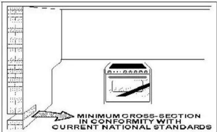
Fig.3
Gas cooking appliances must always evacuate the combustion products by means of hoods connected to chimneys, flues or directly outside (Fig. 4). If a hood cannot be installed, it is possible to use a fan installed on a window or directly facing outdoors, to be operated together with the appliance (Fig. 5), provided that there is strict compliance with the ventilation regulations.
Fig. 4
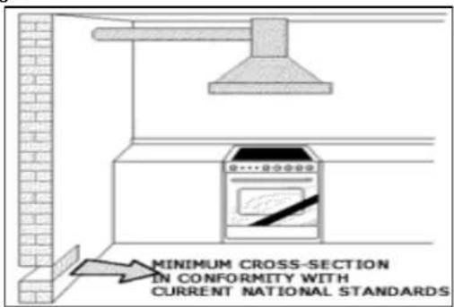
Fig. 5

APPLIANCE GAS CONNECTION
IMPORTANT: This appliance must be installed by an authorized person.
WARNING: The appliance utilizes a threaded 1/2" gas cylindrical male fitting according to UNI-ISO 228-1.
To connect the appliance to the gas network with a flexible rubber hose, a supplemental hose nipple fitting is needed (Fig. 6) which is supplied with the appliance.
This flexible connection can be bought at a hardware store.
Gas regulator
The gas connection is via 1/2" compression. Connect the cooker to the gas supply and check for gas soundness
If using a flexible connection
This appliance is approved for connection with a Flexible Hose, which complies with AS/NZS 1869 (AGA Approved), 10mm ID, class B or D, between 1 - 1.2m long. Connection shall be in compliance with AS 5601, clause 5.12.1.8
When installing the hose restraint device, the appliance anchor point is the rear panel securing.
If using a fixed copper pipe connection
Gas connection
The cooker must be connected to the gas supply with upstream connection of an isolation valve in accordance with the respective valid regulations. We recommend that the isolation valve be fitted prior to the cooker to enable isolation of the cooker from the gas supply. The valve must be easily accessible at all times.
To find out the factory set gas type, see label at rear of cooker.
The gas connection is via 1/2" compression. Connect the cooker to the gas supply and check for gas soundness. NEVER use a naked flame to check for gas leaks.
Gas inlet (mm)- Nat gas
From RH rear side: 35 mm
Up from floor: 590 mm
Gas inlet (mm)- LPG
From RH rear side: 35mm
Up from floor: 675 mm
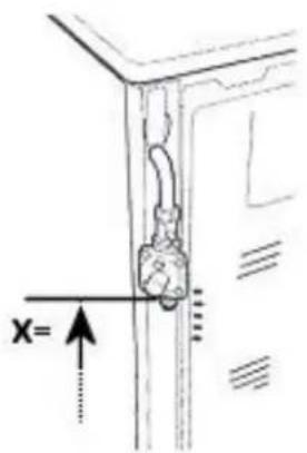
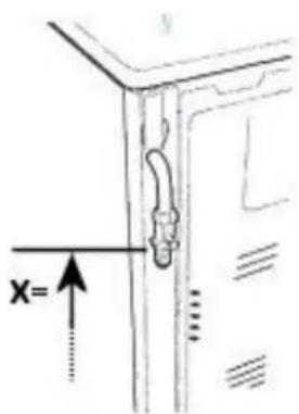
Fig. 6
Gas inlet with different leg heights – X quote in Fig 6 above from the floor in mm.
Min NG: 560 LP: 645
Ref NG: 590 LP: 675
Max NG: 595 LP: 680
TABLE NO. 1
| Energy consumption | FD906WX | ||||
| Burners Gas type | Pressure (kPa) | Injector (mm) | Mj/hr | Watts | |
| Small(Auxiliary) | NaturalU-LPG | 1.02.75 | 0.920.56 | 4.004.2 | 3000 W |
| Medium (semi rapid) | NaturalU-LPG | 1.02.75 | 1.170.73 | 6.77.6 | |
| Large (Rapid) | NaturalU-LPG | 1.02.75 | 1.550.98 | 11.512.9 | |
| *Wok Inner Natural | NaturalU-LPG | 1.02.75 | 0.800.50 | 3.13.2 | |
| *Wok Outer Natural | NaturalU-LPG | 1.02.75 | 1.300.73 | 14.414.5 | |
* The inner & outer wok operates from the same control knob. Please note that the inner wok can operate on its own and the inner and outer wok can also operate together.
Test the operation of the cooker before leaving
Note: These burners have no aeration adjustment
Check correct operation of the ignitions system and operation of burners individually and in combination. Burner flames should be clear blue, with no yellow tipping. If the burners show any abnormality check that the burners are correctly located. If satisfactory performance can not be obtained, contact the local gas utility.
Important
Before leaving instruct the owner in the use of the cooker it should be expressly noted that we cannot accept any liability for direct or indirect damage caused by wrong connection or improper installation. When being repaired, the appliance must always be disconnected from the mains supply; if required, notify our customer service
Support legs
The cookers ore supplied with four transit supports.(One for each corner).
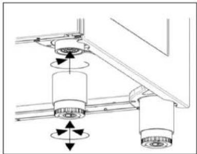
4 support legs ore supplied separately and are fitted on location to the four corners of the lower support frame. Each support leg is pushed over the relevant transit support until flush with the support frame.
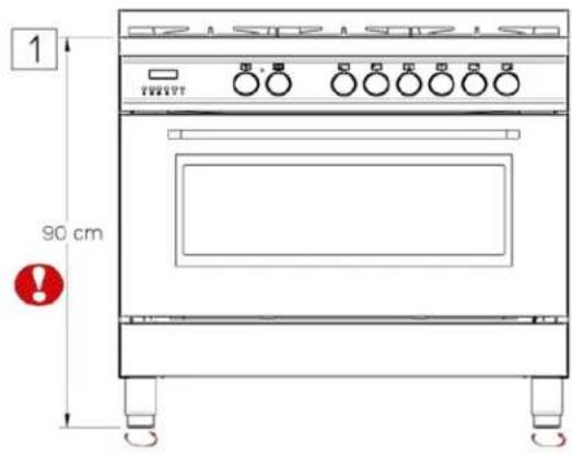
Each leg is adjusted by screwing the lower section in or out as required for fitting to a 900mm bench height. For lower bench tops adjust the height as required. The adjustment range for the leg is 150-185mm. With the legs adjusted to a height of 180mm the hob is located 10mm above the horizontal combustable surface, ref. AS5601
Legs are packed in the top box. Please read the above piece which also relates to the legs.
Legs should be installed with the appliance being near the location of final installation, they are not secure for long transport. After unpacking the range, raise it about a foot to insert the legs in their bases assembled on the lower part of the cooker and lower the range gently to keep any undue strain from legs and mounting hardware. It is recommended to use a pallet or lift jack instead of tilting the unit. Tilting the unit or dragging may easily break the legs.
natural_image
Mechanical assembly diagram showing two cylindrical components connected by rods with directional arrows indicating motion (no text or labels)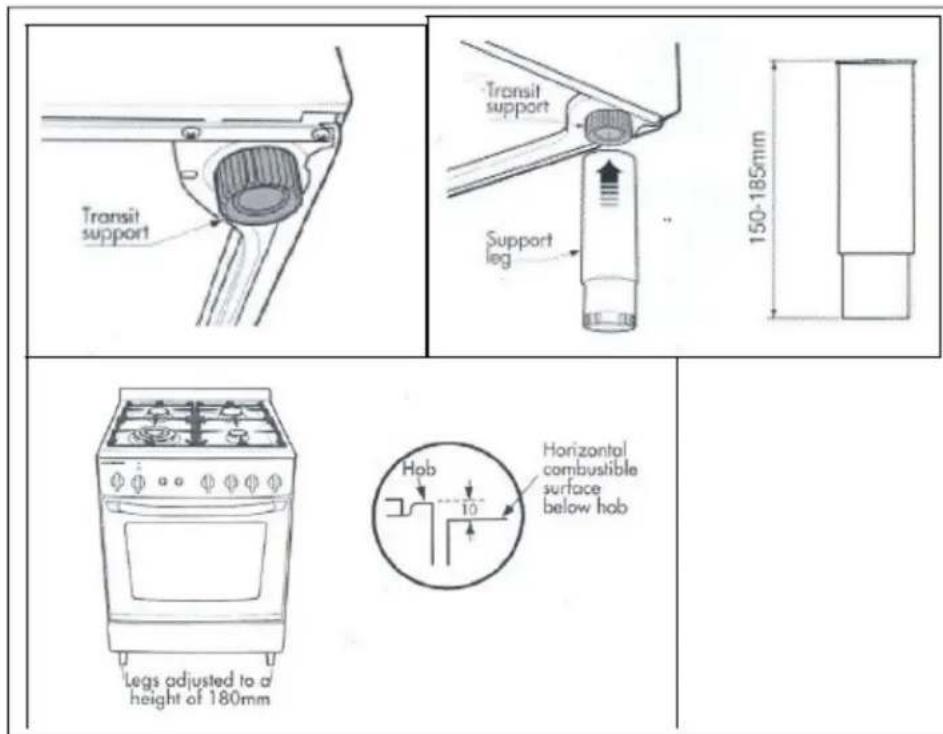
If the legs are not used and the cooker is mounted onto a plinth, fittransit legs to allow for clearance.
Once legs are adjusted to a nominal cooker height of 910 mm, fit the anti-tilt restraint brackets.
ANTI TILT SYSTEM
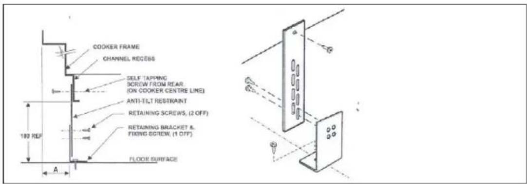
The appliance must be installed using the anti-tipping system provided.
- Fit flat strap to rear of cooker at the center point on lower edge using supplied screws.

- Mark center position of the cooker installed position on floor.

- Measure from rear most pointob to mount pointof strap. (Dimension A), then using Dimension A mark back edge of the bracket on cente line. Use bracket to mark fixing point.
BACKGUARD INSTALLATION INSTRUCTION
Remove the 2 screws that secure the work plan at the rear as shown in below drawing. Arrange the backsplash and secure it to the bottom side with two screws removed. Further secure the Central up stand with the screws supplied with the kit.

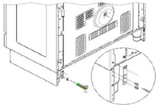
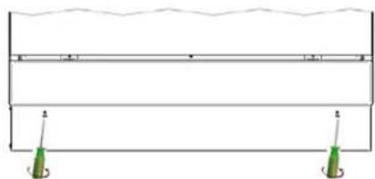
ASSEMBLY INSTRUCTION FOR TOE KICK PANEL
2
natural_image
Technical line drawing of a server rack with a magnified inset showing internal components (no text or symbols)3
LOCATE THE COOKER AND
FIX ANTI-TILT BRACKET

natural_image
Simple line drawing of a rectangular structure with supports and two hanging green objects, no text or symbols present.5
natural_image
Simple line drawing of a rectangular frame with two green supports at the bottom, no text or symbols present.

6

natural_image
Technical diagram showing a mechanical assembly with two views of a bracket and a close-up of a green tool inside (no text or symbols)ADAPTATION TO DIFFERENT TYPES OF GAS
WARNING: Please note that the images below may not be fully correct but are a good guideline as to how the cooktop works.
WARNING: Before performing any maintenance operation, disconnect the appliance from the gas supply and electricity network.
REPLACING THE NOZZLES TO OPERATE WITH ANOTHER TYPE OF GAS
BURNER ADJUSTMENT
Follow the instructions below to change the burner nozzles on the work surface:
1) Pull out the plug from the electric outlet to avoid any type of electric contact.
2) Remove the grids from the work surface (Fig. 7).
3) Remove the burners (Fig. 7).

natural_image
Exploded view diagram of a mechanical assembly showing components like gears and housing (no text or labels)Fig.7
4) Unscrew the nozzles using a 7 mm spanner, and replace them (Fig.8) with those needed for the new type of gas according to what is indicated in Table 1

natural_image
Technical line drawing of a mechanical assembly with no visible text or symbolsFig. 8
Burner "MINIMUM" adjustment:
Work surface burner adjustment: follow the instructions below to adjust the work surface burner minimum:
1) Light the burner and set the knob to the MINIMUM position (small flame).
2) Remove the knob of the valve that is press fit on the rod of that valve.
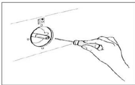
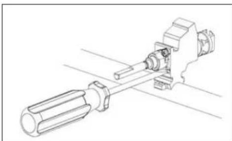
3) If the cooker is not equipped with safety valves on the surface burners, insert a small slotted screwdriver into the hole on the valve rod (Fig. 9) and turn the choke screw to the right or left until the burner flame is adjusted to minimum. If the cooker is equipped with safety valves, the choke valve is not located in the rod hole but on the valve body (Fig. 10).
4) Ensure that the flame does not go out when switching quickly from the MAXIMUM to the MINIMUM position.
natural_image
Hand holding a screwdriver to measure a circular component with a pointer (no text or symbols visible)Fig. 9
natural_image
Technical line drawing of a mechanical assembly with a cylindrical component and a shaft (no text or symbols)Fig. 10
APPLIANCE ELECTRICAL CONNECTION
The electric connection must comply with the current legal standards and regulations.
Before making the connection, check that:
- The system electrical rating and the current outlets are adequate for the maximum power output of the appliance (see the label applied to the bottom of the casing).
- The outlet or the system is equipped with an efficient ground connection in accordance with the current legal standards and regulations. The manufacturer will not be responsible for the non-compliance with these instructions.
Letter L (phase) = brown wire;
Letter N (neutral) = blue wire;
Ground symbol 1- = green-yellow wire;

Fig. 11
- The power cord must be positioned so that a temperature of 75^ C will not be reached at any point.
- Do not use reductions, adapters or splitters since they might cause false contacts and lead to dangerous overheating.
When the connection is made directly to the electric network:
- Use a device that ensures disconnection from the mains in which the contacts are opened to a distance that permits complete disconnection according to the conditions for over-voltage category III.
- Remember that the ground wire must not be interrupted by the circuit-breaker.
- As an alternative, the electric connection can also be protected by a high-sensitivity residual current circuit-breaker but this may be subject to nuisance tripping due to residual humidity in heating elements.
- It is highly recommended to attach the special green-yellow ground wire to an efficient ground system.
WARNING: If the power cord is replaced, the ground wire (yellow-green) connected to the terminal, should be longer than the other wires by about 2 cm.
WARNING: If the supply cord is damaged, it must be replaced by the manufacturer or its service agent or a similarly qualified person in order to avoid a hazard.
TABLE NO. 2: TYPES OF POWER CORDS
| Work surface Operation | Ove n opera- tion | Cross section | |||
| 230V ~ | 230V 3~ | 400V 2N~ | 400V 3N~ | ||
| Only gas burner | Gas oven / Gas grill | 3 × 0.75mm^2 | - | - | - |
| Gas oven / Electric grill | 3 × 1mm^2 | - | - | - | |
| Electric Oven | 3 × 1mm^2 (MH) 3 × 1,5mm^2 (MX M9) | - | - | - | |
| Ventilated Electric Oven | 3 × 1,5mm^2 | - | - | - | |
| Gas burner + 1 hot plate | Gas oven / Gas grill | 3 × 1mm^2 | - | - | - |
| Gas oven / Electric grill | 3 × 1,5mm^2 (MH) 3 × 2,5mm^2 (MX/M9) | - | - | - | |
| Electric Oven | 3 × 1,5mm^2 (MH) 3 × 2,5mm^2 (MX/M9) | - | - | - | |
| Ventilated Electric Oven | 3 × 2,5mm^2 | - | - | - | |
| Gas burner + 2 hot plate | Electric Oven | 3 × 2,5mm^2 | 4 × 1,5mm^2 | 4 × 1,5mm^2 | 5 × 1,5mm^2 |
| Ventilated Electric Oven | 3 × 2,5mm^2 | 4 × 1,5mm^2 | 4 × 1,5mm^2 | 5 × 1,5mm^2 | |
| 4 hot plate | Electric Oven | 3 × 2,5mm^2 | 4 × 1,5mm^2 | 4 × 1,5mm^2 | 5 × 1,5mm^2 |
| Ventilated Electric Oven | 3 × 2,5mm^2 | 4 × 1,5mm^2 | 4 × 1,5mm^2 | 5 × 1,5mm^2 | |
| Ceran | Electric Oven | 3 × 2,5mm^2 | 4 × 1,5mm^2 | 4 × 1,5mm^2 | 5 × 1,5mm^2 |
| Ventilated Electric Oven | 3 × 4mm^2 | 4 × 1,5mm^2 | 4 × 1,5mm^2 | 5 × 1,5mm^2 | |
ATTENTION: The appliance conforms with the regulations AS4551 regarding gas appliances for domestic use and AS/NZS 60335.2.6 regarding electrical safety and CISPR14 regarding electromagnetic compatibility.
THREE-PHASE ELECTRIC CONNECTION
The cookers can also be connected to three-phase systems but normally are factory built for the single-phase 230V connection, and are supplied with a power cord. Based on the connection system used, install the power cord type indicated in table No.2. To use the selected connection system change the jumpers on the terminal strip as indicated in the diagram below. (Fig.12)

Fig. 12
APPLIANCE MAINTENANCE
ATTENTION: IMPORTANT WARNINGS
- For cookers resting on a base ATTENTION: If the cooker rests on a base, take the measures necessary to prevent the cooker from sliding along the support base.
- For cookers with electric ovens ATTENTION: The unit becomes hot during use. Do not touch the heating elements inside the oven.
- For cookers with electric ovens ATTENTION: The accessible parts can become hot during use. Keep children away from the appliance.
- For the food warmer compartment (or drop leaf in our case) ATTENTION: The internal parts of the food warmer can become hot during use.
- For glass doors ATTENTION: Do not use harsh abrasive cleaning products or metal spatulas with sharp edges to clean the oven door's glass since this could scratch the surface and the glass could break.
WARNING: Do not use steam cleaners to clean the appliance.
WARNING: DO NOT MODIFY THIS APPLIANCE
REPLACING PARTS
Before performing any maintenance operations, disconnect the appliance from the gas supply and electricity network.
To replace parts such as knobs and burners, just remove them from the seats without disassembling any part of the cooker.
To replace the oven bulb, just unscrew the protection cap that projects out inside the oven. (Fig.13)

natural_image
Line drawing of a hand holding a small jar with an eye above it, inside a room with shelves (no text or symbols)Fig. 13
WARNING: Before replacing the bulb, disconnect the appliance from the electric power supply.
WARNING: The power cord supplied with the appliance is connected to the appliance with an X type connection (in compliance with standards AS/NZS 60335-1, AS/NZS 60335-2-6 and subsequent amendments) for which it can be installed without the use of special tools, with the same type of cord as the one installed.
If the power cord becomes worn or damaged, replace it based on the information reported in table 2.
WARNING: If the power cord is replaced, the installer shall ensure that the ground cable is longer than the phase cables and also should comply with the warnings regarding the electric connection.
USE AND MAINTENANCE INFORMATION
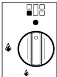
On the control panel, small symbols show the function of each knob or key. Please note that the below control panel drawings are similar to what is placed on your product and that they may not be identical. The operation and below meaning is sufficient to work with and understand your freestanding cooker.
Here are the several controls that a cooker can have:

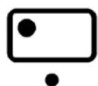


Shows the position of burners on the worktop, the full dot identifies the burner in object.

Shows the running of any oven (Conventional static oven, 9 position switch).

Shows the electric thermostat for the electric fan oven.
WARNING: If the power is cut off, the burners can be lit with matches. When cooking foods with oil and fat, which are very flammable, the user should not leave the appliance unattended. Do not use sprays near the appliance when it is being used. When using the burners, make sure that the handles of the pots are correctly positioned. Keep children away from the appliance.
NOTE: The use of a gas cooking appliance produces heat and humidity in the room where it is installed. Therefore, proper aeration in the room is needed while ensuring that natural ventilation openings remain unobstructed (Fig.3) and activating the mechanical
aeration device/exhaust hood or electric fan (Fig. 4 and Fig.5). Intensive and continuous use of the appliance may require additional aeration, for example by opening a window, or more efficient aeration by increasing the power of the mechanical exhauster, if installed.
USING BURNERS
A diagram is etched on the control panel above each knob which indicates which burner corresponds to that knob. The burners can be ignited in different ways depending on the type of appliance and its specific characteristics.
- Manual lighting (it is always possible even when the power is cut off): Turn the knob anticlockwise that corresponds to the burner selected, setting it to the MAXIMUM position at the etched star (large flame Fig.14) and hold a lit match to the burner.
- Electric ignition: Turn the knob counterclockwise that corresponds to the burner selected, setting it to the MAXIMUM position (large flame Fig.14) and keep on pressing the knob in correspondence with the ignition symbol marked with a star (for cookers equipped with ignition through knob) or press the ignition button marked with a star and release it as soon as the burner has ignited.
natural_image
Pure electrical circuit lines without any symbolsFig. 14
- Burner ignition equipped with safety device (thermocouple) (Fig. 15):
Turn the knob anticlockwise that corresponds to the burner selected, setting it to the MAXIMUM position at the etched star (large flame) Press the knob and activate one of the above-mentioned ignition devices. Once ignited, keep pressing the knob for about 10 seconds to allow the flame to heat the thermocouple. If the burner goes out after releasing the knob, repeat the entire operation.
Note: It is recommended not to try to ignite a burner if the relative flame cap is not in the correct position.

natural_image
Simple line drawing of a three-tiered table with a central bowl and two side bowls (no text or symbols)Fig. 15
Dual Control Wok Burner
The centre burner of the dual wok burner can be used independently of the outer burner to give further flexibility as follows:
To light the central burner, press in the control knob and turn it anti-clockwise to bold single ring position.
- Continue to hold the knob in until the burner lights. Adjust the flame as required. The minimum setting is the lighter single ring position.
- To light the outer burner as well as the central burner, turn the knob to the bold double ring. Adjust the flame as required. The minimum setting for the central and outer burner is the lighter double ring position.
Tips for using burners correctly:
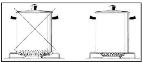
• Use suitable pots for each burner (see tab. 3 and Fig. 16).
natural_image
Two simple line drawings of a portable stove or boiler with heating elements and control knobs (no text or symbols)Fig. 16
- When the liquid is boiling, turn the knob to the MINIMUM position (small flame)
• Always use pots with a cover.
TABLE NO. 3
| BURNER | PAN DIAMETER recommended (cm) |
| Auxiliary | 12 - 14 |
| Semi-rapid | 14-26 |
| Rapid | 18-26 |
| Wok | 22-26 |
ATTENTION: Use pots with a flat bottom (this does not apply to the wok burner)
USING THE ELECTRIC THERMOSTAT
The thermostat supplied with the relative models maintains a constant temperature inside the oven at a specific temperature setting ranging from 50^ C to 250^ C. Please see below image to explain its working.

radar
| Angle (degrees) | Value | |---|---| | 0 | 100 | | 30 | 150 | | 60 | 200 | | 90 | 250 | | 120 | 200 | | 150 | 150 | | 180 | 100 | | 210 | 50 | | 240 | 0 |Turn the knob clockwise and align the selected temperature indicated on the ring with the index etched on the control panel. Thermostat operation is indicated by an orange light which will turn off when the temperature inside the oven is 10^ C greater than the temperature setting, and will turn on when the oven is 10^ C less than the temperature setting. The thermostat can control the oven elements only if the relative switch is in one of the possible oven element operating modes: if the switch is in position 0, the thermostat has not effect on the oven elements, which remain off.
USING THE OVEN FUNCTION KNOB
OVEN FUNCTIONS
Please note that the below images may be different to what is supplied on your freestanding cooker model. However the explanation on how it functions is correct.
This oven has 11 functions as you will see explained below. There are 4 levels in this oven as per the below diagram. (Fig. 17)

Fig. 17
Also there are 2 partially extendable telescopic runners in this model whereby they can be easily glided out for safe use. These extendable racks are not evident in the above picture. Please see your cooker.
The knob on the cooker has 9 functions on it as you can see below (Fig. 18). The '9 switch' installed in the multifunction oven models is used, along with the thermostat, to control the electric fan and the oven elements since they can be turned on by turning the '9 switch' knob and the thermostat knob. Turning just one of the two knobs will not have any effect on the oven except to turn on the oven light or the electric fan when inserted. The electric oven is heated by 4 elements: one on the bottom, two on the top, one circular; turning the switch knob turns on the element relative to the symbol indicated
on the ring but to be activated the thermostat knob must be turned until the orange light turns on indicating that the element has been turned on. Placing the switch knob on any of the nine operating modes turns on the oven light, together with the relative element. Once the temperature and the elements to be used have been set, the oven elements are turned on and off by the thermostat; therefore, it is normal for the orange light to turn on and off while the oven is working.
To turn off the electric oven set the switch knob to position 0 to prevent the thermostat from controlling the elements. Setting the thermostat knob to position 0 turns off the elements but it is still possible, using the switch, to turn on the electric fan and the oven light.
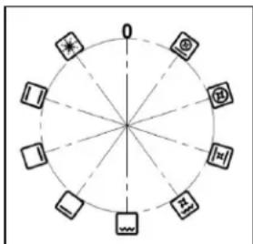
Fig. 18
The switch has 9 different fixed positions corresponding to 9 different types of oven operation:
- the symbol indicates that all the elements and fan have been turned on (pre-heating);
- the symbol 📁 indicates the top and bottom elements have been turned on( traditional);
- the symbol □ indicates that only the bottom element has been turned on;
- the symbol □ indicates that only the top element have been turned on;
- the symbol 📁 indicates that only the grill element has been turned on;
- the symbol 📄 indicates that the top external element, the grill element and the electric fan have been turned on (fan grill);
- the symbol 📄 indicates that the top and bottom elements and the electric fan have been turned on(fan assisted);
- the symbol indicates that the circular element and the electric fan have been turned on( fan forced/ convection);
- the symbol indicates that the bottom element, the circular element and the electric fan have been turned on (pizza function/ fan forced with bottom element)
When the knob is set to one of these nine positions, the oven light is always on, thus indicating that the oven is being energised.
There are also 2 other functions present in these models which do not have an icon but which can be activated as follows:
- Oven Light only: choose a function with the knob, without activating the thermostat.
- Defrost: choose the 'convection' function with the knob, without activating the thermostat.
USING THE PRE HEATING FUNCTION

Pre heating function allow one to reach the preset oven temperature as quickly as possible.
Once it reaches the set temperature, the orange light will go out, select the type of cooking through the switch functions and place the food in to cook.
Note: the preheating function should not be used for cooking but just to preheat the oven.
USING THE PIZZA FUNCTION (FAN FORCED WITH BOTTOM ELEMENT)
When using the oven for the first time it should be operated for a maximum of 30 minutes at a temperature of about 250^ C to eliminate any odours generated by the internal insulation.
Before you start cooking, preheat the oven. After preheating, set the Pizza function, this function ensures homogeneous cooking. Ideal not only for pizzas but also for biscuits and cakes
For cooking the pizza it is recommended that you set the thermostat at the maximum and place the baking try or the grid in positions 3 or 4.
USING THE TRADITIONAL ELEMENT (TOP AND BOTOM ELEMENT)
When using the oven for the first time it should be operated for a maximum of 30 minutes at a temperature of about 250^ C to eliminate any odours generated by the internal insulation. During normal oven use, select the desired cooking temperature using the thermostat knob and wait until the orange light turns off before putting in any food. The oven is equipped with 4 guides at different heights which can be used to insert shelves or the tray. To keep the oven as clean as possible it is recommended to cook meat on the tray or on the shelf that has been inserted inside the tray. Table No. 4 below lists the cooking times and the position of the tray for different types of foods. Personal experience will help to determine any variations in the values reported in the table. In any case, the below table is only a guideline to assist you with your cooking.
TABLE NO. 4: TRADITIONAL FUNCTION - COOKING TABLE
| Temp °C | Height – shelf level | MINUTES | |
| MEAT | |||
| PORK ROAST | 225 | 4/5 | 60-80 |
| BEEF ROAST (YOUNG STEER) | 225 | 4/5 | 60-80 |
| BEEF ROAST | 250 | 4/5 | 50-60 |
| VEAL ROAST | 225 | 4/5 | 60-80 |
| LAMB ROAST | 225 | 4 | 40-50 |
| ROAST BEEF | 230 | 4/5 | 50-60 |
| ROAST HARE | 250 | 4/5 | 40-50 |
| ROAST RABBIT | 250 | 4 | 60-80 |
| ROAST TURKEY | 250 | 4 | 50-60 |
| ROAST GOOSE | 225 | 4 | 60-70 |
| ROAST DUCK | 250 | 4/5 | 45-60 |
| ROAST CHICKEN | 250 | 4/5 | 40-45 |
| FISH | 200-225 | 3 | 15-25 |
| PASTRY | |||
| FRUIT PIE | 225 | 3 | 35-40 |
| TEA CAKE | 175-200 | 3 | 50-55 |
| BRIOCHES | 175-200 | 3 | 25-30 |
| SPONGE CAKE | 220-250 | 3 | 20-30 |
| RING CAKE | 180-200 | 3 | 30-40 |
| SWEET PUFF PASTRIES | 200-220 | 3 | 15-20 |
| RAISIN LOAF | 250 | 3 | 25-35 |
| STRUDEL | 180 | 3 | 20-30 |
| SAVOIA COOKIES | 180-200 | 3 | 40-50 |
| APPLE FRITTERS | 200-220 | 3 | 15-20 |
| SAZOIARDI SANDWICH | 200-220 | 3 | 20-30 |
| TOAST SANDWICH | 250 | 4 | 5 |
| BREAD | 220 | 4 | 30 |
| PIZZA | 220 | 3 | 20 |
USING THE FAN ASSISTED FUNCTION

When using the oven for the first time it should be operated for a maximum of 30 minutes at a temperature of about 250^ C to eliminate any odours generated by the internal insulation.
Before cooking, allow the oven to reach the desired temperature setting waiting for the orange light to turn off. This type of oven is equipped with a fan that creates forced-air circulation in the horizontal direction so that the heat generated by the top and bottom elements is uniformly distributed. Thanks to this type of operation, the oven can be used for different types of cooking at the same time, without changing the taste of each food.
Hot-air circulation guarantees a uniform distribution of heat. Pre-heating the oven is not necessary, but for very delicate pastries, it is recommended to heat the oven before inserting the trays.
The system partially changes the various notions about traditional cooking. Meat no longer needs to be turned while it is cooking and the rotisserie is no longer needed to cook a roast on the spit. Just put the meat directly on the shelf.
TABLE NO. 5
Please note that 'Mar' in the below table refers to the shelf level in the oven
| FAN ASSISTED - COOKING TABLE | |||
| TEMP °C | HEIGHT | MINUTES | |
| MEAT | |||
| PORK ROAST | 210 | 2-Mar | 60/80 |
| BEEF ROAST (YOUNG STEER) | 210 | 2-Mar | 60/80 |
| BEEF ROAST | 230 | 2-Mar | 50/60 |
| VEAL ROAST | 210 | 2-Mar | 60/80 |
| LAMB ROAST | 210 | 2 | 40/50 |
| ROAST BEEF | 215 | 2-Mar | 50/60 |
| ROAST HARE | 230 | 2-Mar | 40/50 |
| ROAST RABBIT | 230 | 2 | 60/80 |
| ROAST TURKEY | 230 | 2 | 50/60 |
| ROAST GOOSE | 200 | 2 | 60/70 |
| ROAST DUCK | 230 | 2-Mar | 45/60 |
| ROAST CHICKEN | 230 | 2-Mar | 40/45 |
| FISH | 180-200 | 2-Mar | 15/25 |
| PASTRY | |||
| FRUIT PIE | 210 | 2 | 35/40 |
| TEA CAKE | 160-180 | 2 | 50/55 |
| BRIOCHES | 160-180 | 2 | 25/30 |
| SPONGE CAKE | 200-230 | 2 | 20/30 |
| RING CAKE | 160-180 | 2 | 30/40 |
| SWEET PUFF PASTRIES | 180-200 | 2 | 15/20 |
| RAISIN LOAF | 230 | 2 | 25/35 |
| STRUDEL | 165 | 2 | 20/30 |
| COOKIES | 165-190 | 2 | 40/50 |
| APPLE FRITTERS | 180-200 | 2 | 15/20 |
| SANDWICH | 180-200 | 2 | 20/30 |
| TOAST SANDWICH | 230 | 2 | 5 |
| BREAD | 200 | 2 | 30 |
USING THE FAN FORCED FUNCTION

When using the oven for the first time it should be operated for a maximum of 30 minutes at a temperature of about 250°C to eliminate any odours generated by the internal insulation.
Before cooking, allow the oven to reach the desired temperature setting waiting for the orange light to turn off. This type of oven is equipped with a circular element around which a fan has been installed that creates forced-air circulation in the horizontal direction. Thanks to this type of operation, the fan forced oven can be used for different types of cooking at the same time, without changing the taste of each food. Hot-air circulation guarantees a uniform distribution of heat. Pre-heating the oven is not necessary, but for very delicate pastries, it is recommended to heat the oven before inserting the trays.
The fan forced system partially changes the various notions about traditional cooking. Meat no longer needs to be turned while it is cooking and the rotisserie is no longer needed to cook a roast on the spit. Just put the meat directly on the shelf.
TABLE NO. 6
| TEMP °C | HEIGHT | MINUTES | |
| MEAT | |||
| PORK ROAST | 160-170 | 2 | 70-100 |
| BEEF ROAST (YOUNG STEER) | 170-180 | 2 | 65-90 |
| BEEF ROAST | 170-190 | 2 | 40-60 |
| VEAL ROAST | 160-180 | 2 | 65-90 |
| LAMB ROAST | 140-160 | 2 | 100-130 |
| ROAST BEEF | 180-190 | 2 | 40-45 |
| ROAST HARE | 170-180 | 2 | 30-50 |
| ROAST RABBIT | 160-170 | 3 | 80-100 |
| ROAST TURKEY | 160-170 | 3 | 160-240 |
| ROAST GOOSE | 160-180 | 3 | 120-160 |
| ROAST DUCK | 170-180 | 2 | 100-160 |
| ROAST CHICKEN | 180 | 2 | 70-90 |
| FISH | 160-180 | 2-Mar | |
| PASTRY | |||
| FRUIT PIE | 180-200 | 2 | 40-50 |
| TEA CAKE | 200-220 | 2 | 40-45 |
| BRIOCHES | 170-180 | 2 | 40-60 |
| SPONGE CAKE | 200-230 | 2 | 25-35 |
| RING CAKE | 160-180 | 2 | 35-45 |
| SWEET PUFF PASTRIES | 180-200 | 2 | 20-30 |
| RAISIN LOAF | 230-260 | 2 | 30-40 |
| STRUDEL | 160 | 2 | 25-35 |
| COOKIES | 150-180 | 2 | 50-60 |
USING THE GRILL FUNCTION

The grill is controlled using the oven's temperature knob, so set switch knob to the relative grill position. The electric grill can be used for grilling on the oven's grill.
The static electric grill must be used with the door closed. The temperature set on the thermostat (when present) must not exceed 150^ C.
Grilling on the shelf: In this case, the shelf supplied is placed on level 1 or 2 and the foods to be grilled are placed on top, while the tray is inserted on the lower levels to collect the cooking juices. Then turn on the grill element switching the thermostat to the relative position (electric oven version).
WARNING: the accessible parts may become very hot while grilling. Keep children away from the appliance while cooking.
USING THE FAN GRILL FUNCTION

The fan assisted electric grill is a special function equipped only on the multifunction oven. Set the function knob switch to the relative position to activate the grill element and the electric fan. Generally, to ensure excellent grilling, place the oven shelf in the middle position while the oven tray should be inserted at the bottom.
IMPORTANT: When using the grill, set the thermostat knob no higher than 175 °C, which is between the 150 °C and 200 °C setting, to avoid overheating the front of the appliance. In fact, fan assisted grilling must be carried out with the door closed.
The cooker is equipped with the cooling fan that starts operation each time a specific temperature of cooker was reached and will stop when the temperature decreases. The fan circulates the air between the control panel and the oven door and also allows the control panel and the oven door stay at a warm temperature during the appliance operation in any condition.
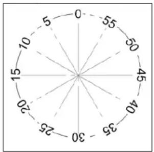
radar
| Angle (degrees) | Value | |---|---| | 0 | 5 | | 30 | 15 | | 60 | 25 | | 90 | 30 | | 120 | 20 | | 150 | 10 | | 180 | 5 | | 210 | 0 | | 240 | -5 | | 270 | -10 | | 300 | -15 | | 330 | -20 | | 360 | -25 | | 390 | -30 | | 420 | -35 | | 450 | -40 | | 480 | -45 | | 510 | -50 | | 540 | -55 |USING THE MINUTE-MINDER
The minute-minder advises the user, with an acoustic signal, when food has been cooked, after a certain time period has elapsed. To use the device, wind the minute-minder by turning the knob clockwise one complete turn. Then turn the knob counterclockwise so that the indicator corresponds with the selected cooking time.
3 KEYS - ELECTRONIC PROGRAMMER
The first start up
The numbers and the A letter on the display are blinking when the oven is switched on for the first time, or after a power cut: the appliance cannot be operated in this condition.
To set the hour and/or to enable the appliance to operate press the M key for at least 2 seconds: the A letter turns off and the numbers now are steady on the display.
The dot (3) starts blinking: press the - or + key to set the hour.
The hour is accepted by the programmer just a few seconds after having released the key. N.B. the appliance can be correctly used for cooking only when you will see on the display the symbol (2).

The symbols on the display:
| 1 | A* | Automatic programme is working. (* in some models there is the writing 'Auto' instead of A). |
| 2 | [W8Z0] | The appliance is ready for manual use (not automatic). |
| 3 | • | When blinking, the programmer is in setting hour mode. |
| 4 |  | Timer set. |
| 5 | - | Decreasing numbers when setting the timer.Also for choosing your desired sound level ( 3 levels available). |
| 6 | M | "Mode" key to access the programming options of the programme. |
| 7 | + | Increasing numbers when setting the timer. |
Timer
The purpose of the timer is a sound signal, which can be set for a max time of 23h59min. once elapsed the set time, the (4) symbol turns off and a sound signal is heard; this sound set off automatically in 7min, or you can stop it by pressing any key of the programmer. To set the timer press the M key for 2 seconds, or to see the (4) symbol blinking. Set the timer by using the + or - keys. Release the + or - key when you have matched your desired time. In a few seconds the current time appears on the display together with the (4) symbol. The countdown starts immediately from now on.
Semi-automatic cooking
Cooking time: Once having selected a cooking function and set the desired temperature, press the M key for a 2 seconds time to access the programming mode. The (4) symbol appears. Release and press again the M key. On the display, the A symbol starts blinking and the "dur" writing appears on the display, then it changes to O'00. Set the cooking time with the - or + keys. (max available time: 10h). The selected time is automatically processed
by the programmer in a few seconds, or you can also touch the M key many times just to see again the current time.
The A and (2) symbols will be on the display. Once the set cooking time is finished, a sound will be heard and the oven automatically switches off. Please see the following paragraphs about how to disable the sound alarm and restarting the oven.
End of cooking
Once having selected a cooking function and set the desired temperature, touch the M key to access the programming mode for at least 2 sec. the (4) symbol switches on. Release and touch again the M key.
On the display the A symbol starts blinking and the writing "dur" appears. Touch again the M key. On the display the writing "End" appears. The last one changes few seconds after with the symbol 0·00.
Set the end of cooking time with the keys - or +. (maximum available time: 10hOOm).
The selected time is automatically processed by the programmer in a few seconds, or you can also touch the M key many times just to see again the current time.
The cooking immediately starts, while on the programmer display the current time is shown again in a few seconds.
The A and (2) symbols will be on the display.
Once the set end of cooking time is finished, a sound will be heard and the oven automatically switches off. Please see the following paragraphs about how to disable the sound alarm and restarting the oven.
Automatic cooking
Set a cooking time following the instructions on the cooking time paragraph, then set the end of cooking time following the instructions on the previous paragraph. (Max available end of cooking time 10h). The oven automatically switches on at a determined time which is the difference between the end of cooking time and the cooking time.
During the waiting time before cooking, which goes from the oven start to the heating, on the display appears the A symbol to show that an automatic program is on and the current time. The oven on is marked by the (2) symbol. Once the set end of cooking time is finished, a sound will be heard and the oven automatically switches off.
Please see the following paragraphs about how to disable the alarm and restarting the oven.
How to disable the sound alarm: To disable the sound just touch one of the keys.
Operating again the oven
Once a semi-automatic or automatic cooking has expired, on the display appear the current time and the blinking A symbol. In this condition, the heating elements and the light bulb of the oven are disabled. To enable again the oven, just touch and keep the M key up to see the symbol (2) on the display and the A symbol disappears.
OTHER FUNCTIONS
How to delete a cooking time (Semi-automatic or Automatic)
To delete a semi-automatic or automatic cooking program, with the A symbol on, touch together the - and + keys for at least 2 seconds or anyway up to see the (2) and the disabling of A symbol.
How to delete the countdown timer
To delete the counting of the timer, which symbol is (4) touch the M key for at least 2 seconds or anyway up to see the (4) symbol blinking. Touch together the - and + keys.
Checking the function settings
The set the remaining time of every cooking function of the programmer can be recalled to the display by entering in program mode with the M key. Touch and keep the M key for almost 2 seconds or anyway up to see the (4) symbol. The remaining time appears on the display, or a series of zero numbers if the timer is disabled. Touch again the M key. On the display appears the "dur" writing, then alternately the remaining time or a series of zero number (disable timer).
By touching again the M key, the end of cooking time appears together with the "End" writing.
How to change the current time or the sound level
With the programmer in standard mode, the (2) symbol is on, touch together the - and + keys for at least 2 seconds or anyway up to see the dot (3) blinking.
To update the hour on the display: touch the + or - keys.
To change the sound level: touch the M key. On the display appears the writing: Ton..followed by a number. Select with the - key your favorite sound level.
Note: number 1 is referred to the highest sound level. The available levels are 3.
Attention: Power cut causes the loss of any program, even the clock; that means the programmer will have to be set again.
CLEANING THE APPLIANCE
CATALYTIC SELF - CLEANING LINERS
The self-cleaning oven differs from the standard one in the fact that its internal surfaces are enamelled with a special microporous material which absorbs and eliminates the greasy particles during the cooking. In case of spillage of greasy liquids, the self-cleaning action becomes not efficient; therefore it will be necessary to clean the oven properly. Proceed in the following way: (a) wipe a humid sponge on the grease stains; (b) heat up the oven to the maximum temperature; (c) wait 5 minutes and then switch off the oven; (d) wait until the oven gets cool again; (e) wipe again the humid sponge on all the surface. Do not use detergent in any case.
WARNING: Before cleaning the appliance, it should be disconnected from the power supply and turn off the main gas feeder valve.
Cleaning the work surface
Periodically clean the burner heads, the enamelled steel grids, the enamelled covers and the flame caps using warm soapy water. Then those parts should be rinsed and thoroughly dried.
Any liquid that overflows from pots must always be removed using a rag.
If it becomes difficult to open or close a valve, do not force it, but immediately request the assistance of the technical service personnel.
Cleaning the enamelled parts
To maintain the original features of the enamelled parts they should be cleaned frequently with soapy water. Never use abrasive powders. Do not leave acidic or alkaline substances on the enamelled parts (vinegar, lemon juice, salt, tomato sauce, etc.) and do not wash the enamelled parts while they are still hot.
Cleaning the STAINLESS steel parts
Clean the parts with soapy water and then dry them with a soft cloth. The shine is maintained by periodically using special products that generally are found in the market. Never use abrasive powders.
Cleaning the burner flame caps
Since the flame caps are resting on the burner, to clean them just remove them from their seat and wash them with soapy water. After they have been thoroughly dried and having checked that the holes are not clogged, they can be replaced in their proper position.
How to remove the door
To thoroughly clean the inside of the oven, it is recommended to disassemble the door by carefully following the instructions described below (Fig. 1 and 3). Insert the hook into the hinged sector. Put the door in a semi-open position and using both hands pull it towards you until it is released from the attachment. To replace the door, do the opposite making sure to insert the two sectors correctly. In addition, the side racks can be removed very easily, by loosening the lock rings that attach them to the oven.
Removing inside glass for cleaning
To remove inside glass door for cleaning follow below fig. 2-3 and 4 and after cleaning the glass reinstall it operating in the reverse way. Use fig. 4-3 and 2.

Removal of roof tray
The roof tray above the grill element can be removed for cleaning.
- Support the grill element with one hand while removing the 2 wing nuts that hold the element in place.
- The element position will drop slightly allowing removal of the top liner.
- Once cleaned and dried, the top liner can be placed back into position, above element, and re-secured with the two wing nuts.
- The liner will only fit into one position so care must be taken to locate it the rear lugs and the front large lip must be facing downwards.
- Do not use the oven unless the liner is fitted and the element has been re-secured with the wing nuts.

natural_image
Technical line drawing of a mechanical device with an inset magnified detail (no text or symbols)TROUBLE SHOOTING
If you have a problem with your appliance check the following before you ring service.
| Problem | What to do |
| Oven or hob not working | Check the electricity is turned on |
| Check your fuses. If the fuse continues to fail please contact service person | |
| Check the circuit breaker | |
| Ensure correct knob is turned | |
| Dry or clean ignition electrodes | |
| Make sure flame ports and ignition areas are clean and dry | |
| Check gas main is on | |
| Ensure cap/crown correctly fitted. | |
| Replace or tighten light globes | |
| Heating up problems | Oven not pre-heated – Pre-heat oven for 30 minutes |
| Check oven door is closed properly | |
| Remove foil or trays from bottom of oven | |
| Change set oven temperature | |
| Preheat your oven before you put the food in to be cooked | |
| Unit smoking/odours | Turn the oven on high to remove protective oils |
| Persistent gas smell – do not operate the oven. Contact service person. | |
| CondensationNote: some condensation is normal and is to be expected during cooking | Reduce the amount of water used for cooking |
| Leave the door open after cooking if food remains in cooker for warming | |
| Oven shelves are tight | Remove oven shelf and re-insert, check correct alignment on runners |
Recommended maintenance schedule for this appliance is 24 months
Affix spare rating plate of the product here or on easily accessible area or in an adjacent cupboard or similar.

natural_image
Empty rounded rectangle with gray border (no text or symbols)We appreciate your feedback.
Please review our products on www.blanco-australia.com
AUSTRALIAN & NEW ZEALAND PRODUCT WARRANTY STATEMENT OF STANDARD WARRANTY CONDITIONS
AUSTRALIAN CUSTOMERS
Our goods come with guarantees that cannot be excluded under the Australian Consumer Law. You are entitled to a replacement or refund for a major failure and for compensation for any other reasonably foreseeable loss or damage. You are also entitled to have the goods repaired or replaced if the goods fail to be of acceptable quality and the failure does not amount to a major failure.
NEW ZEALAND CUSTOMERS
Nothing herein contained shall be construed in any way as excluding or limiting your rights under the Consumer Guarantee Act 1993.
OUR WARRANTY
This product is also covered by the manufacturer's warranty set out in this document (Our Warranty).
Our Warranty is for a period of twenty four (24) months from the date of purchase and for dishwasher & refrigeration appliances will have an additional thirty six (36) months after the first twenty four (24) months on the wash motor for dishwashers & on the Sealed System (PARTS only Compressor & condenser etc) for refrigeration appliances. The labour cost to replace these parts is the responsibility of the customer.
This is in addition to (and does not exclude, restrict or modify) any rights or remedies to which you may already be entitled under the Australian consumer Law or the New Zealand Consumer Guarantee Act 1993 relating to this product.
Our Warranty (which is subject to the conditions below) covers rectification free of charge of any fault arising from defective materials or components, or faulty workmanship. The product will be repaired or replaced at the option of Blanco, and all costs of installation, removal, cartage, freight travelling expenses and insurance are to be paid by the customer.
Our Warranty is subject to the following conditions:
-
That the purchaser contact Blanco prior to any product repair.
-
That the purchaser carefully follows all instructions provided with the product and complies with all relevant electrical & plumbing regulations in their State when installing the product.
-
That the purchaser carefully follows the instructions provided in the owner's handbook relating to the proper use and care of the product and does not use the product for any purpose other than the DOMESTIC use for which it has been designed. If the appliance is used in commercial applications or for rental purposes, Our Warranty is limited to a warranty of Twelve (12) months covering all parts with Three (3) months on any labour cost of service or repair.
SERVICE AREA
The provision of service under Our Warranty is limited by the boundary / territory area of the nearest service centre. Travelling cost incurred for service outside this area is not covered by Our Warranty and service will incur commercial cost to be paid by the customer regulated by the number of kilometres travelled beyond the service area. These costs will be disclosed to you for acceptance by you prior to your claim being processed.
Microwave ovens must be returned to your nearest Authorised Service Centre for repair as they are a carry in serviceable appliance.
WHAT IS COVERED: By Our Warranty
During the warranty period, Blanco or its authorised Service Centre will at no extra charge, if your appliance is readily accessible without the need of special equipment and subject to the terms and conditions of this warranty, repair or replace any parts which it considers defective.
WHAT IS NOT COVERED: By Our Warranty
- Products installed damaged or incomplete or not in compliance with the relevant electrical & plumbing regulations in their State.
- Normal wear and tear e.g. cleaning, light globes, filters etc.
- Failure resulting from power surges and electrical storms.
- Insect or vermin infestation.
- Unauthorised repairs or use of non genuine Blanco parts.
- Any failure caused by the product not being used in accordance with the instruction and the installation manual provided with the product.
- Misuse or abuse, including failure to properly maintain or service.
- The clearing of blockages in pumps and hoses.
- Damage which occurs during delivery or installation.
- Claims to product surface coating due to liquid or solid spill-overs, accidental damage or damage caused from cleaning products not recommended by Blanco.
HOW TO CLAIM OUR WARRANTY
You will need to contact Blanco in Australia or New Zealand by using the contact details below.
IN AUSTRALIA
Blanco is distributed by Shriro Australia Pty Ltd
Locked Bag 5002, Kingsgrove, NSW, 2208
Phone: 1300 795 572 Fax: 1800 686 413
Email: customercare@shriro.com.au
Web: http://www.blanco-australia.com/
IN NEW ZEALAND
Blanco is distributed by Monaco Corporation
(Member of Shriro Australia Pty Ltd)
PO Box 4399, Shortland St, Auckland, 1140
Phone: 09 415 6000 Fax: 09 415 7060
Email: service@shriro.com.au
Web: http://www.blanco-australia.com/
Note: Please complete the following details when you have unpacked the product and staple this card with the purchase invoice or sales docket.
Model No.
Date of Purchase
Serial No.
Retailer.

- Instruction Manual for
- Blanco 90cm
- Freestanding Cooker
- FD906WX
- DISPOSAL INFORMATION
- CONTENTS
- PRODUCT DESCRIPTION
- INSTALLER TECHNICAL INFORMATION
- USE AND MAINTENANCE INFORMATION 22
- INSTALLING THE APPLIANCE
- ROOM VENTILATION
- APPLIANCE GAS CONNECTION
- Gas regulator
- If using a flexible connection
- If using a fixed copper pipe connection
- Gas connection
- Test the operation of the cooker before leaving
- Important
- Support legs
- ANTI TILT SYSTEM
- BACKGUARD INSTALLATION INSTRUCTION
- ASSEMBLY INSTRUCTION FOR TOE KICK PANEL
- ADAPTATION TO DIFFERENT TYPES OF GAS
- REPLACING THE NOZZLES TO OPERATE WITH ANOTHER TYPE OF GAS
- BURNER ADJUSTMENT
- APPLIANCE ELECTRICAL CONNECTION
- When the connection is made directly to the electric network:
- THREE-PHASE ELECTRIC CONNECTION
- APPLIANCE MAINTENANCE
- ATTENTION: IMPORTANT WARNINGS
- REPLACING PARTS
- USE AND MAINTENANCE INFORMATION
- USING BURNERS
- Dual Control Wok Burner
- Tips for using burners correctly:
- USING THE ELECTRIC THERMOSTAT
- USING THE OVEN FUNCTION KNOB
- OVEN FUNCTIONS
- USING THE PRE HEATING FUNCTION
- USING THE PIZZA FUNCTION (FAN FORCED WITH BOTTOM ELEMENT)
- USING THE TRADITIONAL ELEMENT (TOP AND BOTOM ELEMENT)
- USING THE FAN ASSISTED FUNCTION
- USING THE FAN FORCED FUNCTION
- USING THE GRILL FUNCTION
- USING THE FAN GRILL FUNCTION
- USING THE MINUTE-MINDER
- KEYS - ELECTRONIC PROGRAMMER
- The first start up
- Timer
- Semi-automatic cooking
- End of cooking
- Automatic cooking
- Operating again the oven
- OTHER FUNCTIONS
- How to delete a cooking time (Semi-automatic or Automatic)
- How to delete the countdown timer
- Checking the function settings
- How to change the current time or the sound level
- CLEANING THE APPLIANCE
- CATALYTIC SELF - CLEANING LINERS
- Cleaning the work surface
- Cleaning the enamelled parts
- Cleaning the STAINLESS steel parts
- Cleaning the burner flame caps
- How to remove the door
- Removing inside glass for cleaning
- Removal of roof tray
- TROUBLE SHOOTING
- We appreciate your feedback.
- Please review our products on www.blanco-australia.com
- AUSTRALIAN & NEW ZEALAND PRODUCT WARRANTY STATEMENT OF STANDARD WARRANTY CONDITIONS
- AUSTRALIAN CUSTOMERS
- NEW ZEALAND CUSTOMERS
- OUR WARRANTY
- SERVICE AREA
- WHAT IS COVERED: By Our Warranty
- WHAT IS NOT COVERED: By Our Warranty
- HOW TO CLAIM OUR WARRANTY
- IN AUSTRALIA
- IN NEW ZEALAND
Brand : BLANCO
Model : FD906WX
Category : Oven