
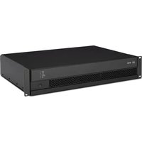
IPS 1700 - Receiver RCF - Free user manual and instructions
Find the device manual for free IPS 1700 RCF in PDF.


| Brand | RCF |
| Model | IPS 1700 |
| Product Type | Receiver |
| Dimensions (H x W x D) | 2U rack mount, approx. 88 x 483 x 250 mm |
| Weight | Approx. 5.5 kg |
| Power Supply | 100-240 V AC, 50/60 Hz |
| Power Consumption | 40 W (max) |
| Frequency Response | 20 Hz - 20 kHz (±1 dB) |
| Input Connectivity | XLR, 1/4" TRS, RCA |
| Output Connectivity | XLR, 1/4" TRS, speakON |
| Cooling System | Variable speed fan |
| Protection Features | Short circuit, thermal, overcurrent |
| Compliance | CE, RoHS |
| Cleaning | Use dry cloth; avoid solvents |
| Maintenance | Check ventilation grilles monthly |
| Spare Parts | Contact RCF authorized service |
| Repairability | Modular design, serviceable by qualified technician |
Frequently Asked Questions - IPS 1700 RCF
User questions about IPS 1700 RCF
0 question about this device. Answer the ones you know or ask your own.
Ask a new question about this device
Download the instructions for your Receiver in PDF format for free! Find your manual IPS 1700 - RCF and take your electronic device back in hand. On this page are published all the documents necessary for the use of your device. IPS 1700 by RCF.
USER MANUAL IPS 1700 RCF
USER MANUAL MANUALE D'USO
IPS 700 IPS 1700 IPS 2700 IPS 3700
- AMPLIFIERS
- AMPLIFICATORI
TABLE OF CONTENTS INDICE

ENGLISH
SAFETY PRECAUTIONS 4
DESCRIPTION 6
UNPACKING AND INSTALLATION 6
FRONT PANEL 7
REAR PANEL 8
OPERATION MODES 9
SPEAKON CONNECTOR WIRING 11
COOLING REQUIREMENTS 11
SPECIFICATIONS 12
ITALIANO
AVVERTENZE PER LA SICUREZZA 14
DESCRIZIONE 16
Before connecting and using this product, please read this instruction manual carefully and keep it on hand for future reference.
The manual is to be considered an integral part of this product and must accompany it when it changes ownership as a reference for correct installation and use as well as for the safety precautions.
RCF S.p.A. will not assume any responsibility for the incorrect installation and / or use of this product.
WARNING: To prevent the risk of fire or electric shock, never expose this product to rain or humidity.
This device is intended for indoor use only.
SAFETY PRECAUTIONS
- All the precautions, in particular the safety ones, must be read with special attention, as they provide important information.
2. POWER SUPPLY FROM MAINS
- The mains voltage is sufficiently high to involve a risk of electrocution: never install or connect this product when its power cord is plugged in.
- Before powering up, make sure that all the connections have been made correctly and the voltage of your mains corresponds to the voltage shown on the rating plate on the unit, if not, please contact your RCF dealer.
- The metallic parts of the unit are earthed by means of the power cord.
- An apparatus with CLASS I construction shall be connected to a mains socket outlet with a protective earthing connection.
- Protect the power cord from damage. Make sure it is positioned in a way that it cannot be stepped on or crushed by objects.
- To prevent the risk of electric shock, never open this product: there are no parts inside that the user needs to access.
-
The mains plug is used as the disconnect device and it shall remain readily operable.
-
Make sure that no objects or liquids can get into this product, as this may cause a short circuit.
This apparatus shall not be exposed to dripping or splashing. No objects filled with liquid (such as vases) and no naked sources (such as lighted candles) shall be placed on this apparatus.
- Never attempt to carry out any operations, modifications or repairs that are not expressly described in this manual.
Contact your authorized service centre or qualified personnel should any of the following occur:
- The product does not function (or functions in an anomalous way).
- The power cord has been damaged.
- Objects or liquids have got into the product.
-
The product has been subject to a heavy impact.
-
If this product is not used for a long period, disconnect its power cord from mains.
-
If this product begins emitting any strange odours or smoke, switch it off immediately and disconnect its power cord.
IMPORTANT

WARNING

-
The terminals marked with the symbol are HAZARDOUS LIVE and their connection is to be made by an INSTRUCTED PERSON or the use of ready-made cables is required.
-
Do not connect this product to any equipment or accessories not foreseen.
For suspended installation, only use the dedicated anchoring points and do not try to hang this product by using elements that are unsuitable or not specific for this purpose.
Also check the suitability of the support surface to which the product is anchored (wall, ceiling, structure, etc.), and the components used for attachment (screw anchors, screws, brackets not supplied by RCF etc.), which must guarantee the security of the system / installation over time, also considering, for example, the mechanical vibrations normally generated by transducers.
To prevent the risk of falling equipment, do not stack multiple units of this product unless this possibility is specified in this user manual.
- RCF S.p.A. strongly recommends this product is only installed by professional qualified installers (or specialised firms) who can ensure correct installation and certify it according to the regulations in force.
The entire audio system must comply with the current standards and regulations regarding electrical systems.
- Supports and trolleys
The equipment should be only used on trolleys or supports, where necessary, that are recommended by the manufacturer. The equipment / support / trolley assembly must be moved with extreme caution.
Sudden stops, excessive pushing force and uneven floors may cause the assembly to overturn.
-
Mechanical and electrical factors need to be considered when installing a professional audio system (in addition to those which are strictly acoustic, such as sound pressure, angles of coverage, frequency response, etc.).
-
Hearing loss
Exposure to high sound levels can cause permanent hearing loss. The acoustic pressure level that leads to hearing loss is different from person to person and depends on the duration of exposure. To prevent potentially dangerous exposure to high levels of acoustic pressure, anyone who is exposed to these levels should use adequate protection devices.
When a transducer capable of producing high sound levels is being used, it is therefore necessary to wear ear plugs or protective earphones.
See the technical specifications in loudspeaker instruction manuals to know their maximum sound pressure levels.
-
Do not obstruct the ventilation grilles of the unit. Situate this product far from any heat sources and always ensure adequate air circulation around the ventilation grilles.
-
Do not overload amplifiers. Check that amplifier outputs are not shorted.
-
Never force the control elements (keys, knobs, etc.).
-
Do not use solvents, alcohol, benzene or other volatile substances for cleaning the external parts of this product.
Use a dry cloth.
NOTES ABOUT AUDIO SIGNAL CABLES
To prevent the occurrence of noise on microphone / line signal cables, use screened cables only and avoid putting them close to:
- Equipment that produces high-intensity electromagnetic fields.
- Mains cables.
- Loudspeaker lines.
DESCRIPTION

IPS series includes four models of two-channel power amplifiers designed for professional use in touring racks and installed sound systems.
The four models only differ in their rated power:
- IPS 700 delivers up to 2 x 300 W into 4 Ω (bridged: 600 W into 8 Ω)
- IPS 1700 delivers up to 2 x 450 W into 4 Ω (bridged: 900 W into 8 Ω)
- IPS 2700 delivers up to 2 x 1100 W into 4 Ω (bridged: 2200 W into 8 Ω)
- IPS 3700 delivers up to 2 x 1500 W into 4 Ω (bridged: 3000 W into 8 Ω).
MAIN FEATURES:
- Fast response and low distortion
- Easy to configure in STEREO / PARALLEL (mono) / BRIDGE modes
- Extensive protective circuits ensure high reliability and operating safety
- Front panel SIGNAL / CLIP / FAULT LED indicators
- XLR input connectors
- SPEAKON output connectors
- Limiter on each channel.
UNPACKING AND INSTALLATION


Check the carton box and its contents to see if there is any sign of damage (should the amplifier be damaged, immediately inform your local distributor / dealer and the forwarder). It is always advisable to keep the packing materials, even if the amplifier has arrived in good condition.
Input and output cables are not included.
Each amplifier needs 2 units of a standard 19" rack cabinet.
Four holes for rack mounting are on the front panel ears.
Rear mounting ears give additional support.
The amplifier should not be installed in a place with:
- Too high temperature, dust or excessive humidity.
- Fog machine outputs oriented towards the amplifier.
- Exhaust air ventilators.
- Permanent vibrations.
- High-intensity electromagnetic fields (due to transformers, transmitters, etc.).

1 POWER switch
Push to turn on / off the amplifier.
Before switching the amplifier on, check all cables and turn fully counterclockwise both channel level controls 3.
2 POWER LED
When lit, the amplifier is switched on.
3 Control (one per channel) to adjust the output level of the respective amplifier channel.
Turn clockwise to increase the output level (0 dB = max. level), turn counterclockwise to decrease.
IF THE AMPLIFIER IS SET TO BRIDGE MODE, USE THE CHANNEL 1 CONTROL ONLY.
4 FAULT LED (one per channel)
When lit, it indicates the internal protection intervention (due to overload, short-circuit, thermal drift, fault) and the respective channel is muted.
As soon as the problem is solved, this LED will be dark.
When turning the amplifier on, this LED stays lit for three seconds.
5 CLIP LED (one per channel)
It blinks when the signal level reaches the clipping point, causing the limiter intervention of the respective channel.
If it stays lit continuously, the input signal level is excessive.
6 SIGNAL LED (one per channel)
When lit, it indicates the signal presence (above -40 dBu) at the respective input.


PIEDINATURA CONNETTORE XLR: 1 MASSA, 2 SEGNALE AUDIO (+), 3 SEGNALE AUDIO (-)

7 CH1 INPUT
Channel 1 balanced audio input (female XLR connector).
8 CH1 LINK
Channel 1 balanced parallel audio output (male XLR connector).
This output is linked in parallel with the channel 1 input and is useful to link another amplifier.
9 CH2 INPUT (STEREO MODE ONLY)
Channel 2 balanced audio input (female XLR connector).
10 CH2 LINK
Channel 2 balanced parallel audio output (male XLR connector).
This output is linked in parallel with the channel 2 input and is useful to link another amplifier.
11 MODE switch
Before turning the amplifier on, set the amplifier mode selector to the right position among BRIDGE, PARALLEL (mono) and STEREO.
See the 'Operation modes' manual section.
12 SENSITIVITY switch
Set the sensitivity switch to either 0.775 V or 1.4 V, which is input signal voltage required to get the maximum power output from the amplifier.
13 CH 1 OUTPUT
Channel 1 output to loudspeakers (SPEAKON connector).
If the amplifier is set to BRIDGE mode, only connect this output.
See both 'Operation modes' and 'SPEAKON connector wiring' manual sections.


CH 2 OUTPUT
Channel 2 output to loudspeakers (SPEAKON connector).
Do not use this output if the amplifier is set to BRIDGE mode.
See both 'Operation modes' and 'SPEAKON connector wiring' manual sections.

Power cord input.
Connect the power cord only to a mains socket outlet with a protective earthing connection.

RESET push-button
Push this button to (try to) reset the amplifier when is muted due to the thermal protection.
OPERATION MODES

STEREO MODE
Make sure the amplifier is switched off before setting the MODE switch 11 to STEREO In stereo mode, both channels operate independently and each front panel level control affects its respective output.
Minimum load impedance is 4 Ω per output.
Loudspeakers shall be connected to the outputs 1 (left channel) and 2 (right channel).

PARALLEL (MONO) MODE
Make sure the amplifier is switched off before setting the MODE switch 11 to PARALLEL.
In mono mode, both channels are linked to input 1 (therefore receiving the same signal). Each front panel level control affects its respective output, allowing you to set (if necessary) different levels.
Minimum load impedance is 4 Ω per output.
Loudspeakers shall be connected to the outputs 1 and 2.
NOTE THAT ONLY THE AMPLIFIER INPUTS ARE LINKED IN PARALLEL. THIS IS NOT AN OUTPUT PARALLEL MODE. NEVER CONNECT BOTH OUTPUTS IN PARALLEL!


BRIDGE MODE
Make sure the amplifier is switched off before setting the MODE switch 11 to BRIDGE. In 'bridge' (mono) mode, both amplifier channels work with the same input signal, but with inverse phases. The result is a doubling of the output voltage in order to get a double power (on a double impedance load).
Connect the CH 1 input and output only.
The output level is adjusted only by the channel 1 front panel control.
Pay attention to the output SPEAKON wiring: pin 1+ positive, pin 2+ negative.
Minimum load impedance is: 8 Ω.

STEREO / PARALLEL (MONO) MODE
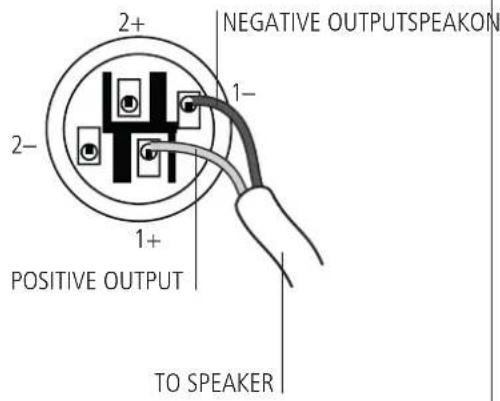
BRIDGE MODE

COOLING REQUIREMENTS

IPS amplifiers have a forced air cooling system to maintain a low operating temperature. Make sure there is enough space around the front of all amplifiers (to allow air to enter) and around to allow the heated air to exit. If amplifiers are rack-mounted, do not use doors or covers on the front and the rear of the rack cabinet(s).
| IPS 700 IPS 1700 | IPS 2700 IPS 3700 | ||||
| RATED OUTPUT POWER | 4 Ω - stereo (per channel) | 300 W 450 W 1100 | W 1500 W | ||
| 8 Ω - stereo (per channel) | 150 W 330 W 700 W | W 1200 W | |||
| 8 Ω - bridged 600 W | 900 W 2200 W 3000 | W | |||
| Frequency response 20 Hz ÷ 20 kHz (+0 -1 dB, 1 W) | |||||
| Total harmonic distortion < 0.5% (20 Hz ÷ 20 kHz) | |||||
| Damping factor > 200 (8 Ω, 10 ÷ 400 Hz) | |||||
| Slew rate > 10 V / μs | |||||
| Signal / noise ratio > 100 dB | |||||
| Crosstalk -75 dB (1 kHz) | |||||
| Input sensitivity for full rated power (8 Ω) | 0.775 V / 1.4 V | ||||
| Input impedance 20 kΩ (balanced), 10 kΩ (unbalanced) | |||||
| Protections | DC, internal fault, input overload, RF interference, unmatched load, output short-circuit, thermal drift, power supply over-current | ||||
| Cooling | Internal heat sinks and forced ventilation (speed regulated fan) | ||||
| Operating voltage | 115 V / 230 V (according to the model), 50-60 Hz | ||||
| Power consumption | 350 W 350 W 700 W | W 800 W | |||
| Inrush current | 8 A | 11 A | 15 A | 22 A | |
| Power cord input | IEC 10 A | IEC 10 A | IEC 16 A | IEC 16 A | |
| Dimensions (19" rack, 2 U) | width | 482 mm | 482 mm 482 mm | 482 mm | |
| height | 88 mm | 88 mm | 88 mm | 88 mm | |
| depth | 255 mm | 255 mm 255 mm | 324 mm | ||
| Net weight | 9.5 kg | 11.2 kg | 12.2 kg | 16.6 kg | |
AVVERTENZE PER LA SICUREZZA

IMPORTANTE
Except possible errors and omissions.
RCF S.p.A. reserves the right to make modifications without prior notice.

- USER MANUAL MANUALE D'USO
- IPS 700 IPS 1700 IPS 2700 IPS 3700
- TABLE OF CONTENTS INDICE
- ENGLISH
- ITALIANO
- SAFETY PRECAUTIONS
- POWER SUPPLY FROM MAINS
- IMPORTANT
- WARNING
- NOTES ABOUT AUDIO SIGNAL CABLES
- DESCRIPTION
- MAIN FEATURES:
- UNPACKING AND INSTALLATION
- POWER switch
- POWER LED
- Control (one per channel) to adjust the output level of the respective amplifier channel.
- FAULT LED (one per channel)
- CLIP LED (one per channel)
- SIGNAL LED (one per channel)
- CH1 INPUT
- CH1 LINK
- CH2 INPUT (STEREO MODE ONLY)
- CH2 LINK
- MODE switch
- SENSITIVITY switch
- CH 1 OUTPUT
- CH 2 OUTPUT
- OPERATION MODES
- STEREO MODE
- PARALLEL (MONO) MODE
- BRIDGE MODE
- COOLING REQUIREMENTS
- AVVERTENZE PER LA SICUREZZA
- IMPORTANTE
Brand : RCF
Model : IPS 1700
Category : Receiver