
SI 7120 - Monitor RCF - Free user manual and instructions
Find the device manual for free SI 7120 RCF in PDF.


| Product Type | Monitored Logical Input Board |
| Brand | RCF |
| Model | SI 7120 |
| Category | Monitor (Accessory for MU 7100) |
| Compatible With | RCF MU 7100 Unit |
| Number of Boards per MU 7100 | Up to 2 |
| Monitored Input Channels | 2 (control inputs 1 and 2) |
| Normal State Line Resistance | 10 kΩ |
| Alarm State Line Resistance | 470 Ω |
| Fault Detection Range | Open line >20 kΩ, short <400 Ω |
| Fault Indication | Red LED on board, system fault report |
| Connector | Fits MU 7100 control input connector |
| Operating Voltage | 24 V DC (supplied by MU 7100) |
| Safety Precautions | Install by qualified personnel; avoid exposure to rain or humidity |
| Maintenance | Keep dry; clean with a dry cloth; no user-serviceable parts |
| Repairability | Contact authorized RCF service center for repairs |
| Typical Application | Fire alarm or emergency system line monitoring |
Frequently Asked Questions - SI 7120 RCF
User questions about SI 7120 RCF
0 question about this device. Answer the ones you know or ask your own.
Ask a new question about this device
Download the instructions for your Monitor in PDF format for free! Find your manual SI 7120 - RCF and take your electronic device back in hand. On this page are published all the documents necessary for the use of your device. SI 7120 by RCF.
USER MANUAL SI 7120 RCF
OWNER MANUAL MANUALE D'USO
DXT 7000
AC 7212
SI 7120
RO 7102
SYSTEM
- SPARE AMPLIFIER CHANGE-OVER BOARD FOR LT 7208
- SCHEDA COMMUTAZIONE AMPLIFICATORE DI RISERVA PER LT 7208
- MONITORED LOGICAL INPUT BOARD FOR MU 7100
- SCHEDA INGRESSI LOGICI MONITORATI PER MU 7100
- DRY OUTPUT CONTACT BOARD FOR MU 7100
- SCHEDA CON RELÈ E CONTATTI "PULITI" PER MU 7100
INDEX INDICE

ENGLISH
SAFETY PRECAUTIONS
AC 7212 - SPARE AMPLIFIER CHANGE
OVER BOARD FOR LT 7208
SI 7120 - MONITORED LOGICAL INPUT
BOARD FOR MU 7100
RO 7102 - DRY OUTPUT CONTACT
BOARD FOR MU 7100
ITALIANO
AVVERTENZE PER LA SICUREZZA
AC 7212 - SCHEDA COMMUTAZIONE
AMPLIFICATORE DI RISERVA PER LT 7208
SI 7120 - SCHEDA INGRESSI LOGICI
MONITORATI PER MU 7100
RO 7102 - SCHEDA CON RELÈ E
CONTATTI "PULITI" PER MU 7100
4
6
9
10
14
16
19
20
SAFETY PRECAUTIONS

IMPORTANT NOTES
Before connecting and using these products, please read this instruction manual carefully and keep it on hand for future reference. The manual is to be considered an integral part of these products and must accompany them when changing ownership, as a reference for correct installation and use as well as for the safety precautions.
RCF S.p.A. will not assume any responsibility for the incorrect installation and / or use of these products.
WARNING: To prevent the risk of fire or electric shock, never expose these products to rain or humidity.
SAFETY AND OPERATING PRECAUTIONS
- All the precautions, in particular the safety ones, must be read with special attention, as they provide important information.
- Loudspeaker lines can have a sufficiently high voltage (i.e. 100 V) to involve a risk of electrocution: complete the installation and all connections before turning the system on.
- Assure all connections have been made correctly.
- Protect all cables from damage; make sure they are positioned in a way that they cannot be stepped on or crushed by objects.
- Never attempt to carry out any modifications or repairs. Contact your authorized service centre or qualified personnel when any product does not work properly.
- Should any product emit a strange odour or even smoke, turn the system off immediately.
- Do not connect any equipment or accessories not foreseen.
- RCF S.p.A. strongly recommends these products are only installed by professional qualified installers (or specialised firms) who can ensure a correct installation and certify it according to the regulations in force. The entire audio system shall comply with the current standards and regulations regarding electrical systems.
- There are numerous mechanical and electrical factors to be considered when installing a professional audio system (in addition to those which are strictly acoustic, such as sound pressure, angles of coverage, frequency response, etc.).
IMPORTANT NOTES

WARNING

10. Hearing loss
Exposure to high sound levels can cause permanent hearing loss. The acoustic pressure level that leads to hearing loss is different from person to person and depends on the duration of exposure. To prevent potentially dangerous exposure to high levels of acoustic pressure, anyone who is exposed to these levels should use adequate protection devices. When a transducer capable of producing high sound levels is being used, it is therefore necessary to wear ear plugs or protective earphones.
- To prevent inductive effects from causing hum, noise and a bad system working, loudspeaker lines should not be laid together with other electric cables (mains), microphone or signal cables connected to amplifier inputs.
- All loudspeaker lines shall have wires with a suitable section (twisted, if possible, to reduce inductive effects due to surrounding electro-magnetic fields) and a sufficient electrical insulation.
Refer to local regulations since there may be additional requirements about cable characteristics.


AC 7212 boards can be used in DXT 7000 systems.
Each board has 2 main 70-100V loudspeaker line inputs, spare amplifier input and output, 2 relays.
AC 7212 'X2' terminal shall be directly connected to a pair of LT 7208 loudspeaker 50-70-100 V outputs. A board can control 2 outputs (in pairs: 1-2, 3-4, 5-6 or 7-8).
The LT 7208 override voltage output is used to activate the AC 7212 relay in case of the main amplifier is faulty and switch the spare amplifier output to the respective loudspeaker line.
BLOCK DIAGRAM
![graph TD A["Amp 1"] --> C["Node"] B["Spare Amp"] --> C C --> D["Zone 1"] E["Amp 2"] --> F["Node"] G["Zone 2"] --> H["Node"] F --> I["to next AC 7212"] H --> I](/content/2026/05/939254/images/dcf4d3ef8e05f3b6b323988392416c963eb271447f16c0f594a458957c09a580.jpg)
BLOCK DIAGRAM

pin X1 terminal (to be wired)
- zone 1 loudspeaker line out +
- zone 1 loudspeaker line out –
- ground
- input for the spare amplifier out +
- input for the spare amplifier out -
- zone 2 loudspeaker line out +
- zone 2 loudspeaker line out —
- ground
- spare amplifier link output +
- spare amplifier link output –
pin X2 terminal (directly connected to LT 7208)
- zone 1 loudspeaker line out +
- zone 1 loudspeaker line out –
- ground
- zone 1 spare amp. control +
- zone 1 spare amp. control –
- zone 2 loudspeaker line out +
- zone 2 loudspeaker line out –
- ground
- zone 2 spare amp. control +
- zone 2 spare amp. control –
X1 TERMINAL WIRING DIAGRAM
X1 TERMINAL WIRING DIAGRAM
![graph LR A["MU 7100 SYSTEM / LOCAL BUS OVERRIDE AUDIO OUT"] -->|audio| B["SPARE AMP."] B --> C["AC 7212"] C --> D["ZONE 1"] C --> E["ZONE 2"] C --> F["SPARE AMP. LINK OUT TO NEXT AC7212"] style A fill:#f9f,stroke:#333 style B fill:#ccf,stroke:#333 style C fill:#cfc,stroke:#333 style D fill:#fcc,stro…](/content/2026/05/939254/images/623c1acac801c6c0f478a7f44b092a2bac8fac9030718839b5cbf0a136c9ca70.jpg)
The spare amplifier audio input is to be connected to either the MU 7100 system bus override audio out (when the spare amplifier serves the entire system) or the MU 7100 local bus override audio out (when the spare amplifier is for a single MU 7100 only).


MU 7100 - SYSTEM / LOCAL BUS OVERRIDE AUDIO OUT
RJ-11 CONNECTOR
Pins: 1 ground, 2 audio (+ hot), 3 audio (- cold), 4-5 relay contact
There can be up to four AC 7212 connected to a single LT 7208 unit.
The LT 7208 override voltage output is used to control the AC 7212 relay control, so it is not available as override command for attenuator relays. If override commands are needed, these can be obtained by using MU 7100 control outputs and external relays.
Use the DXT 7000 configuration software (open the 'Amplifiers' window) to set the 'CTRL LT 7208 Function' of each respective output to 'Change-Over Amp CTRL'.

![graph LR subgraph RCF_LT7208 direction TB A["0V"] --> B["10"] C["24V"] --> D["9"] E["GND"] --> F["8"] G["-"] --> H["7"] I["+"] --> J["6"] K["0V"] --> L["5"] M["24V"] --> N["4"] O["GND"] --> P["3"] Q["-"] --> R["2"] S["+"] --> T["1"] end subgraph AC_7212 direction TB U["10"] --> V["-"] W["9"] --> X["…](/content/2026/05/939254/images/872a256b71d95f4c90f3064362cc0d4ba9f5e54447594fdc999e29b197f776d8.jpg)
SI 7120 – MONITORED LOGICAL INPUT BOARD FOR MU 7100

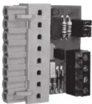
For instance, a fault on the first line (control input 1) returns the activation of the control input 3; a fault on the second line (control input 2) returns the activation of the control input 4.
If one or both lines are in the fault state, the board red LED will turn on.
The SI 7120 board fits the MU 7100 unit control input connector.
Each MU 7100 can be equipped with two SI 7120 boards.
The other end of the control line shall be equipped with two resistors.
The normal state resistance to be inserted is 10 kΩ.
When an alarm command is active, the resistance shall be 470 Ω.
If the line resistance value gets out of the proper range, the SI 7120 board will return a fault indication to the system.

![graph TD A["Normal"] -->|10k| B["SI 7120"] C["Alarm"] -->|470| B D["Normal"] -->|10k| E["SI 7120"] F["Alarm"] -->|470| E B --> G["MU 7100"] E --> G H["DETECTOR"] --> I["SI 7120"] H --> J["SI 7120"] H --> K["SI 7120"] L["DETECTOR"] --> M["MU 7100"] N["Line fault in 1 (C.I. 3/7)"] --> O["SI 7120"] P["…](/content/2026/05/939254/images/3c34d4887805cfa9abe07efeb7a16ec01f9c8ec841af80e57a22ea212bdac469.jpg)

RO 7102 – DRY OUTPUT CONTACT BOARD FOR MU 7100

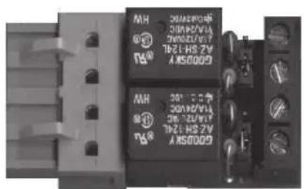
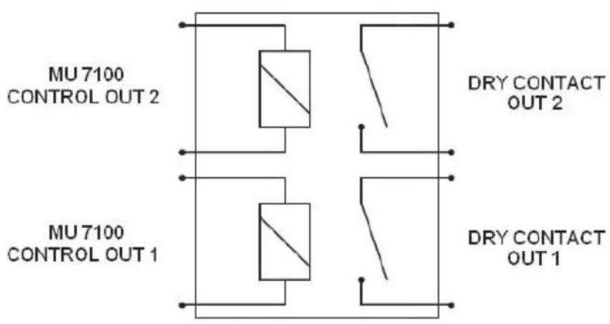
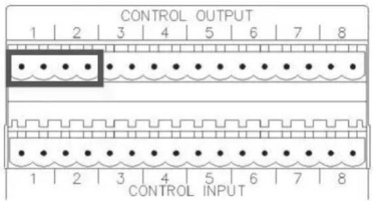
A RO 7102 board can be directly connected to a pair of MU 7100 control outputs.
It converts the 2 MU 7100 open-collector 'control outputs' to 2 dry closing contacts that can be used as commands for external devices. It also has resistors needed for monitored alarm lines.
Each screw terminal is suitable for a wire having a 0.4 ÷ 1.5 mm2 section.
Max. voltage and current applicable on a contact: 24 V dc - 0.5 A.
The MU 7100 unit has 8 control outputs, so it is possible to connect up to 4 RO 7102 boards.

MU 7100 CONTROL OUTPUTS 1 – 2
MONITORING
The RO 7102 board includes 2 pairs of resistors needed for line monitoring. Normally, a 10 kΩ resistor is inserted into the line.
When the contact is closed, the line is switched to a 470 Ω resistor. If line resistance is higher than 20 kΩ, the line is considered 'open' (fault); if the resistance is lower than 400 Ω, the line is considered a short-circuit.
Each line can be either 'monitored' or 'non-monitored'. This selection is made through the JP1 jumper (for the first dry closing contact) and the JP2 jumper (for the second dry contact).
JP1 AND JP2 JUMPERS
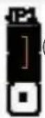
JP1: 1-2 Dry contact output 1 non-monitored line (off: open line, on: short)
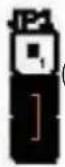
JP1: 2-3 Dry contact output 1 monitored line (off: 10 kΩ, on: ca. 450 Ω)

JP2: 1-2 Dry contact output 2 non-monitored line (off: open line, on: short)

JP2: 2-3 Dry contact output 2 monitored line (off: 10 kΩ, on: ca. 450 Ω)
MONITORING
JP1 AND JP2 JUMPERS
![graph TD subgraph_MU_7100_control_out["MU 7100 control outputs"] A["Component 1"] --> B["Component 2"] B --> C["Component 3"] C --> D["10k"] C --> E["470"] end subgraph_Non_Monitored_line["Non-monitored line"] F["Component 1"] --> G["Component 2"] G --> H["Component 3"] H --> I["10k"] H --> J["470"]…](/content/2026/05/939254/images/30d6d9383d77ebd28c13a6265302281b5222e029939356e31e6e73f64b16405b.jpg)
AVVERTENZE PER LA SICUREZZA

IMPORTANTE

![graph LR subgraph RCF_LT7208 direction TB A["0V"] --> B["10"] C["24V"] --> D["9"] E["GND"] --> F["8"] G["LINE 2 OUT"] --> H["7"] I["+"] --> J["6"] K["0V"] --> L["5"] M["24V"] --> N["4"] O["GND"] --> P["3"] Q["LINE 1 OUT"] --> R["2"] S["+"] --> T["1"] end subgraph AC 7212 direction TB U["10"] --> V["…](/content/2026/05/939254/images/53f25dbc3005af06f2a1fd2499989580722a79637a2e98481c1de55230f4e038.jpg)
SI 7120 – SCHEDA INGRESSI LOGICI MONITORATI PER MU 7100




- OWNER MANUAL MANUALE D'USO
- DXT 7000
- AC 7212
- SI 7120
- RO 7102
- SYSTEM
- INDEX INDICE
- ENGLISH
- ITALIANO
- SAFETY PRECAUTIONS
- IMPORTANT NOTES
- SAFETY AND OPERATING PRECAUTIONS
- WARNING
- HEARING LOSS
- X1 TERMINAL WIRING DIAGRAM
- MU 7100 - SYSTEM / LOCAL BUS OVERRIDE AUDIO OUT
- SI 7120 – MONITORED LOGICAL INPUT BOARD FOR MU 7100
- RO 7102 – DRY OUTPUT CONTACT BOARD FOR MU 7100
- MONITORING
- JP1 AND JP2 JUMPERS
- AVVERTENZE PER LA SICUREZZA
- IMPORTANTE
- SI 7120 – SCHEDA INGRESSI LOGICI MONITORATI PER MU 7100
Brand : RCF
Model : SI 7120
Category : Monitor