
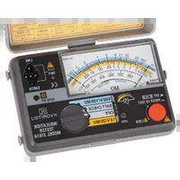
KEW 5410 - Measurement Kyoritsu - Free user manual and instructions
Find the device manual for free KEW 5410 Kyoritsu in PDF.


| Product Type | Digital Multimeter (True RMS) |
| Model | KEW 5410 |
| Brand | Kyoritsu |
| Display | 6000 counts LCD with backlight |
| DC Voltage Range | 600mV to 1000V (5 ranges) |
| AC Voltage Range | 600mV to 1000V (5 ranges, True RMS) |
| DC Current Range | 600µA to 10A (5 ranges) |
| AC Current Range | 600µA to 10A (5 ranges, True RMS) |
| Resistance Range | 600Ω to 60MΩ (7 ranges) |
| Capacitance Range | 40nF to 1000µF |
| Frequency Range | 10Hz to 1MHz |
| Continuity Test | Audible buzzer |
| Diode Test | Yes |
| Safety Rating | CAT IV 600V, CAT III 1000V |
| Power Supply | 2 x AA batteries (1.5V) |
| Dimensions | 180 x 87 x 47 mm |
| Weight | Approx. 370g (including batteries) |
| Auto Power Off | Yes (approx. 15 minutes) |
| Data Hold | Yes |
| Relative Mode | Yes |
| Backlight | Yes |
| Maintenance | Clean with dry cloth; replace batteries when low |
| Spare Parts | Test leads, batteries, fuse (F500mA/600V) |
| Repairability | User replaceable fuse and batteries; refer to manual for other repairs |
Frequently Asked Questions - KEW 5410 Kyoritsu
User questions about KEW 5410 Kyoritsu
0 question about this device. Answer the ones you know or ask your own.
Ask a new question about this device
Download the instructions for your Measurement in PDF format for free! Find your manual KEW 5410 - Kyoritsu and take your electronic device back in hand. On this page are published all the documents necessary for the use of your device. KEW 5410 by Kyoritsu.
USER MANUAL KEW 5410 Kyoritsu
2-1MethodofremovingtheCover....4
2-2MethodofstoringtheCover....4
3.Feature....5
4. Specification....6
5.InstrumentLayout....9
6. Measurementprinciple....11
7.Preparation....12
7-1ConnectionofTestLeads....12
7-2SettingofMeasurementRange....12
7-3SettingofI n .....13
7-4SettingofTestPolarity....13
7-5Backlight....13
8.Measurements....14
8-1Connection....14
8-2VoltageMeasurement....14
8-3RCDTest....15
8-4Re moteTest....15
8-5Operatingtime....19
9.BatteryReplacement....20
10.StrapBelt Assembly....21
1. SafetyWarnings
This instrument has been designed, manufactured and tested according to following standards, and delivered in the best condition after passing quality control tests.
IEC61010-1
Measurement Category CAT III 300V / CAT II 400V Pollution degree 2
IEC61010-2-030
IEC61010-031
IEC61557-1, 6
IEC60529 IP54
Thisinstructionmanualcontainswarningsandsafetyruleswhichhave tobeobservedby theusertoensuresafeoperationoftheinstrument andtomaintainitinsa fecondition.Therefore,readthroughthese operatinginstructionsbeforeusingtheinstrument.
⚠ WARNING
- Read through and understand the instructions contained in this manual before using the instrument.
- Keep the manual at hand to enable quick reference whenever necessary.
● The instrument is to be used only in its intended applications.
● Understand and follow all the safety instructions contained in the manual. It is essential that the above instructions are adhered to. Failure to follow the instructions may cause injury, instrument damage and/or damage to equipment under test. Kyoritsu is by no means liable for any damage resulting from the instrument in contradiction to this cautionary note.
● The symbol ⚠ indicated on the instrument means that the user must refer to the related parts in the manual for safe operation of the instrument. It is essential to read the instructions wherever the ⚠ symbol appears in the manual.

DANGER is reserved for conditions and actions that are likely to cause serious or fatal injury.

WARNINGis reserved for conditions and actions that can cause serious or fatal injury.

CAUTION is reserved for conditions and actions that can cause injury or instrument damage.
⚠️ DANGER
● This instrument is designed to measure the earth-to-line voltage 90 \~ 264V and the line-to-line voltage up to 440V (50/60Hz). Do not exceed the maximum allowable input of any measuring range.
- Do not attempt to make measurement in the presence of flammable gasses. Otherwise, the use of the instrument may cause sparking, which can lead to an explosion.
- Keep your fingers and hands behind the protective fingerguard during measurement.
- Set the Function Switch to any desirable Range before making a measurement. Do not power on the instrument with it being connected to the live circuit.
● Never attempt to use the instrument if its surface or your hand are wet.
● Never open the Battery Cover during a measurement.
- Verify proper operation on a known source before use or taking action as a result of the indication.
● The instrument should be used only in its intended applications or conditions. Otherwise, safety functions equipped with the instrument do not work, and instrument damage or serious personal injury may be caused.
WARNING
● Never attempt to make any measurement if any abnormal conditions, such as a broken cover or exposed metal parts are present on the Instrument and test leads.
- Do not install substitute parts or make any modification to the instrument. Return the instrument to your local KYORITSU distributor for repair or re-calibration in case of suspected faulty operation.
- Set the Function Switch to the OFF position when removing the Battery Cover for battery replacement.
- If the overheat symbol “ 📋 ” appears on the display, disconnect the instrument from the measuring point and allow to cool down.
- Stop using the test lead if the outer jacket is damaged and the inner metal or color jacket is exposed.
CAUTION
- Do not expose the instrument to the direct sun, extreme temperatures or dew fall.
● Firmly insert the plugs of test leads to the appropriate terminals. - Set the Function switch to the OFF position after use, and remove the batteries if the instrument is to be stored and will not be in use for a long period.
- Use a damp cloth with neutral detergent for cleaning the instrument. Do not use abrasives or solvents.
- Do not store the instrument if it is wet.
Symbols used on the instrument
The following symbols are used and marked on the instrument and in the instruction manual. Please carefully check before starting to use the instrument.
 | Protected throughout by DOUBLE INSULATION or REINFORCED INSULATION |
 | User must refer to the explanations in the instruction manual. |
 | Earth Ground |
 | This instrument satisfies the marking requirement defined in the WEEE Directive (2002/96/EC). This symbol indicates separate collection for electrical and electronic equipment. |
Measurement categories (Over-voltage categories)
To ensure safe operation of measuring instruments, IEC 61010 establishes safety standards for various electrical environments, categorized as O to CAT IV, and called measurement categories.
Higher-numbered categories correspond to electrical environments with greater momentary energy, so a measuring instrument designed for CAT III environments can endure greater momentary energy than one designed for CAT II.
O : Circuits which are not directly connected to the mains power supply.
CAT II : Primary electrical circuits of equipment connected to an AC electrical outlet by a power cord.
CAT III : Primary electrical circuits of the equipment connected directly to the distribution panel, and feeders from the distribution panel to outlets.
CAT IV : The circuit from the service drop to the service entrance, and to the power meter and primary overcurrent protection device (distribution panel).

2. Procedure of removing Cover
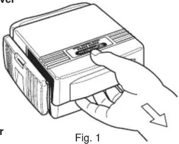
KEW5410 has a dedicated Cover to protect against impacts from the outside and prevent the operation part, the LCD and the Connector Block from becoming dirty. The Cover can be detached and put on the backside of the main body during measurement.
2-1 Method of removing the Cover
Slide and pull the Cover in the direction of an arrow.
natural_image
Line drawing of a hand inserting a device into a device labeled 'Fig. 1' (no text or symbols on the device itself)2-2 Method of storing the Cover
Turn the Cover, slide and push it in the direction of arrow.

natural_image
Line drawing of a hand inserting a digital multimeter into a device (no text or symbols visible)Fig. 2
3.Feature
ThisinstrumentisadigitalRCDTestertomeasurethetriptimeandtripout currentofRCDs.Italsoequipsthefunctiontomeasurethevoltage.
● MeasurementofRCDtriptime
Conductingtestingofratedresidualnon-operatingcurrentsatx1/2Range, measuringRCDtriptimeatx1andx5Ranges.
● Measurementoftripoutcurrent
Measuring tripout current by varying current automati cally.
RemoteTest
EnablingausertoholdtheTestLeadswithhisbothhandsbylockingt the TestButton.
● VoltageMeasurement
Carryingoutaconstantmeasurementofvoltageinthestand-bymodeat eachRange.
● Auto-detectionofContactvoltage
DetectingthevoltagetoearthofEarthelectrodesorProtectiveconductors duringRCDtest - whenapplyingtestcurrents - atmeasurementusing EARTHinordertopreventelectricalshockscausedbythedamaged earth.
MeasurementwillbeceasedatAC50V(AC100V "x5rangeonly)ormore.
● Dust-andWater-proof
Dust-andWater-proofconstruction(designedtoIEC60529IP54)
- Backlight
Facilitatingworkingatdimlyilluminatedlocations.
4. Specification
● Measuring range and accuracy
(23°C±5°C, relative humidity 75% or less)
| Range | Rated Voltage | Test current IΔn | Measuring range | Accuracy |
| x 5 | 100V±10%200V+32%/-10%400V±10%50 / 60Hz | 15 / 30 / 50/ 100mA | Testing time0ms ~ 200ms | Trip Time±(1%rdg+3dgt) |
| Test Current+2% ~ +8% | ||||
| x 1 | 15 / 30 / 50/ 100 / 200/ 500mA | Testing time0ms ~ 2000ms | Trip Time±(1%rdg+3dgt) | |
| Test Current+2% ~ +8% | ||||
| x 1 / 2 | Testing time0ms ~ 2000ms | Trip Time±(1%rdg+3dgt) | ||
| Test Current-8% ~ -2% | ||||
| AUTO RAMP (mA) | 15 / 30 / 50/ 100 / 200/ 500mA | 40%~110% of IΔn (goes up by 5%)Testing time300ms x 15steps | Test Currentat each step-4% ~ +4% |
* Only the RCD type G (without trip out time-delay) can be tested at Auto Ramp Test; type S (time-delay) cannot be tested.
Voltage Measurement
| Measuring range | Accuracy |
| 80V ~ 450V50 / 60Hz | ±(2%rdg+4dgt) |
● Applied standards
: IEC61010-1, -2-030 Measurement Category CAT III 300V / CAT II 400V, Pollution degree 2
IEC61010-031
IEC61557-1, 6
IEC60529 IP54
EN61326-1 (EMC)
EN50581 (RoHS)
● Display
: 1999counts (3 1/2digits), Large LCD
● Used location : Altitude up to 2000m, indoor use
● Operating temperature : 0^ C \~ 40^ C , relative humidity 85% & humidity (no condensation)
● Storage temperature : -20^ 60^ , relative humidity 85% & humidity (no condensation)
● Withstand Voltage : AC3470V / 5 sec. (between electrical circuit and enclosure)
● Insulation resistance : 50MΩ or more / 1000V (between electrical circuit and enclosure)
- Sleep Function : 1. Automatically enters Sleep mode in 3 min after the last switch operation (current consumption 75uA). This function doesn't work at voltage measurements. To exit from the Sleep mode, set the Function switch to OFF position once, and re-set it to the Range at which a measurement to be conducted.
- Backlight turns off in 1 min after it lights up.
● Dimension : 186mm x 167mm x 89mm
● Weight : 965g
● Power Source : DC12V / Size AA battery R6P (SUM-3) x 8pcs
● Possible number of Measurements : 1200 times or more (measure every 30sec at x1/2 Range, IΔn =100mA)
● Accessories : Instruction manual x 1pce Strap belt x 1pce Test lead M7128 x 1set (red & black cords) Test lead with alligator clip M7129 x 1 set Cord case x 1pce Long pin M8017 x 2pcs Size AA battery R6P(SUM-3) x 8pcs
- Operating error
Operating error (B) is an error obtained under the nominal operating conditions, and calculated with the intrinsic error (A), which is an error of the instrument used, and the error (En) due to variations.
$$ B = \pm (A | + 1. 1 5 \sqrt {E _ {1} ^ {2} + E _ {2} ^ {2} + E _ {3} ^ {2} + E _ {5} ^ {2} + E _ {8} ^ {2}}) $$
A : Intrinsic error
E_1 : Variation due to changing the position
E_2 : Variation due to changing the supply voltage
E_3 : Variation due to temperature
E_5 : Variation due to the resistance of Probe *
E_8 : Influence by the variation in System Voltage
* Probe = auxiliary Earth electrode to be used for the sampling of electric potentials during measurements
| IΔn Probe resistance | |
| 15mA Less than | 200 Ω |
| 30mA Less than | 100 Ω |
| 50/100/200/500mA Less than 20 Ω | |
KEW5410 Max Operating Error (IEC61557)
| Range Max Operating Error | |
| x 5 | test current 0% ~ +10% |
| time measurement ±10% | |
| x 1 | test current 0% ~ +10% |
| time measurement ±10% | |
| x 1/2 | test current -10% ~ 0% |
| AUTO RAMP (mA) | ±6% |
5. Instrument Layout

- LCD
- 0° / 180° Button (Polarity change)
- IΔn Button
- Test Button
- Backlight Button
- Function Switch

2. Test lead with alligator clip M7129A
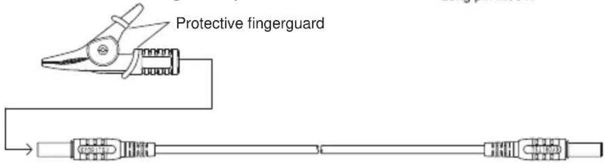
Fig. 4
Protective figerguard :
It is a part providing protection against electrical shock and ensuring the minimum required air and creepage distances.
\* Long pin for M7128
The Tip pin of M7128 can be replaced with the Long pin M8017.
(1) Unscrew and remove ① shown in Fig.4 and remove the Tip pin.
(2) Install the Long pin and tighten ①.
6. Measurement principle
This instrument has a constant current circuit, and drives leakage currents (I) between LINE-NEUTRAL as illustrated in Fig.5 to activate RCDs, moreover, can output and measure leakage currents flowing to the earth as shown in Fig.6.
- Trip time measurement:
Measure and display the time between the start of driving leakage currents (I) and trip of the RCD.
● Trip out current measurement:
Increase the leakage current gradually from the 40% of IΔn, the current value when RCD trips is displayed.
Influence of the fluctuations in system voltages is less on this instrument due to the incorporated constant current circuit.

Fig. 5 Fig. 6
7. Preparation
7-1 Connection of Test Leads
Connect the test lead properly.
- Connect the test lead M7128; red cord to the load of the Connector block and black cord to the power supply.
- When using the test lead with Alligator clip, connect the test lead M7128 (red) to the load of Connector block and M7129 to the power.
7-2 Setting of Measurement Range
Turn the Function Switch and power on the in strument, then select any appropriate Ranges.
Range construction: There are 4 Ranges on this instrument.
| x 5 | For trip time measurement :Apply a current 5 times bigger than IΔn to measure RCD trip time. |
| x 1 | For trip time measurement :Apply IΔn to measure RCD trip time. |
| x 1/2 | For the test - rated residual non-operating current :Apply a half of IΔn to confirm the RCD under test doesn't trip. |
| AUTO RAMP | For trip out current measurement :Vary a testing current in the range of 40% ~ 110% of IΔn to measure the trip out current on the RCD. |
WARNING
Do not power on the instrument with it being connected to the live circuit. Stop using the test lead if the outer jacket is damaged and the inner metal or color jacket is exposed.
⚠️ DANGER
Keep your fingers and hands behind the protective fingerguard during measurement.
7-3 Setting of IΔn
Balance the IΔn of the instrument and of the RCD by using the IΔn Button.
● Default value : 30mA
- Selectable values at x 5 Range are 15, 30, 50 and 100mA; 200 and 500mA are not available (Black arrow mark “▼” on the LCD indicates the selected value). In case that 200 or 500 mA is selected at any Ranges other than x 5 Range and set the Function Switch to x 5 Range, the value automatically restores to 30mA.
7-4 Setting of Test Polarity
Press the 0^/180^ Button and select the polarity for test.
When the instrument is connected as illustrated in Fig.7, 8; current flows from the load to power in positive half cycle at 0^ and flows from the load to power in negative half cycle at 180^ , and when it is connected as illustrated in Fig.9; current flows from the load to earth in positive half cycle at 0^ and flows from the load to earth in negative half cycle at 180^ .
● Default polarity : 0°
7-5 Backlight
Press the Backlight Button and turns on the backlight to facilitate working at dimly illuminated location.
● Backlight turns off automatically in 1 min after it lights up. Press the button again to turn it on.
8. Measurements
8-1 Connection
Connect the instrument according to Fig. 7, 8, 9.
⚠️ DANGER
This instrument is designed to measure the earth-to-line voltage 90 \~ 264V and the line-to-line voltage up to 440V (50/60Hz). Do not exceed the maximum allowable input of any measuring range.
WARNING
● Power on the instrument before connecting to the measuring point.
- Prior to a measurement, confirm that the instrument isn't in the Sleep mode. If it is in the sleep mode, set the Function Switch to OFF position first and do preparation for measurement according to “Chapter 7. Preparation”.
Then connect the instrument to the measuring point.
CAUTION
Disconnect the load of the RCD to be tested before connecting the instrument. Otherwise, it may influence on the test results.
8-2 Voltage Measurement
The instrument automatically measure voltages when it detects input of voltage.
⚠️ DANGER
Indication of “Lo V” is displayed on the LCD when the measured voltage is less than 80V; “Hi V” is displayed with audible warning when the measured voltage is 450V or higher. Disconnect the instrument from the measuring point immediately when “Hi V” is displayed on the LCD, and stop further measurements. The Test Button is disabled while “Lo V” or “Hi V” is displayed on the LCD, and RCD test cannot be performed.
8-3 RCD test
Press the Test Button while voltage is displayed on the LCD, then RCD test starts.
● x1/2, x1, x5 Ranges
Measured RCD trip time will be displayed on the LCD. When the RCD under test doesn't trip, "OL ms" will be displayed instead.
Test results must be matched with the operating times mentioned at clause 8.5.
● AUTO RAMP Range
Measured trip out current will be displayed on the LCD. When the RCD under test doesn't trip, "OL mA" will be displayed instead.
Measured results are kept displayed until the Function Switch, I△n Button or 0° /180° Button is operated. Restore the tripped RCD and apply voltages; then a Voltage measurement can be re-started.
8-4 Remote Test
Connect the instrument as illustrated in Fig.7, 8, 9 with the Test Button pressed down & locked.
Then voltage measurement is conducted for about 1 sec and RCD test starts automatically.
Restore the tripped RCD with the Test Button on the instrument turned & locked, and apply voltages. Then the instrument measures voltages for about 1 sec and starts RCD test automatically again.

DANGER
Voltage to earth of Earth electrodes or Protective conductors is automatically detected during RCD test - when applying test currents - at measurement using EARTH in order to prevent electrical shocks caused by the damaged earth. When the detected voltage at RCD test exceeding AC50V (AC100V "x5 range" only), "Uf Hi V" is displayed after pressing the Test Button and halt the measurements.

WARNING
- When overheat symbol “☐” appears on the LCD, disconnect the instrument from the measuring point and allow to cool down.
- Replace the batteries with new ones immediately when the Low battery warning “B” starts flashing.
- Setting of IΔn may not be proper or the instrument isn't connected to the object under test correctly when “no” is displayed on the LCD. The IΔn of the instrument and the RCD under test should be the same. Check the connection prior to measurements.

CAUTION
- Measured results may be influenced by a presence of voltage between protective conductors and EARTH at measurement using protective conductors. When testing the circuit with earthed Neutral wire, check the connection between Neutral and Earth before starting measurements. Measured results may be influenced by a presence of voltage between Neutral and EARTH.
● Measured results may be influenced by a presence of leakage current in the circuit under test. Presence of leakage current may be doubt if any electric field exists in the other earth equipments. - Resistance of earthed electrodes in the circuit under test with a Probe - auxiliary earthed electrode - should be 200 (I n = 15mA ) / 100 (I n = 30mA ) / 20 (I n = 50/100/200/500mA ), or less.
● Equipment following the RCD, e.g. capacitors or rotating mashinery, may cause a significant lengthening of the measured trip time.
- Restore the tested RCD after measurements.
● Neutral - Line
Connect the “PRIMARY” of the Connector Block to the Neutral of the power of RCD, and the “SECONDARY” of the Connector Block to the Line of the load of RCD.

Fig. 7
! DANGER
This instrument is designed to measure the earth-to-line voltage 90 \~ 264V and the line-to-line voltage up to 440V (50/60Hz). Do not exceed the maximum allowable input of any measuring range.
● Line - Line
Connect the “PRIMARY” of the Connector Block to L2 of the power of RCD, and the “SECONDARY” of the Connector Block to L1 of the load of RCD.

Fig. 8
DANGER
This instrument is designed to measure the earth-to-line voltage 90 \~ 264V and the line-to-line voltage up to 440V (50/60Hz). Do not exceed the maximum allowable input of any measuring range.
- Earth - Line
Connect the “PRIMARY” of the Connector Block to Earth, and the “SECONDARY” of the Connector Block to Line of the load of RCD.
Connection using Earth

Fig. 9

Leakage currents may flow to RCD (A), which is installed in the power supply of the RCD (B) under test, when current flows to the EARTH; so RCD (A) may trip as well.
Fig. 10
DANGER
Extra caution should be taken when applying current to EARTH for tests since the other RCDs (see Fig.10) may operate and damage the devices connected to the instrument and cause accidents.
8-5 Operating time
Tripping time is the time needed by the RCD to trip at a rated residual operating current of IΔn. The standard values of tripping time are defined by IEC 61009 and IEC 61008 are listed in the table below for IΔn and 5IΔn.
| Type of RCD IΔn (x1) 5IΔn (x5) | ||
| General(G) | 300msmax allowed value | 40msmax allowed value |
| Selective(S) | 500msmax allowed value | 150msmax allowed value |
| 130msmin allowed value | 50msmin allowed value | |
9. Battery Replacement

DANGER
- Do not open the Battery Cover if the instrument is wet.
● Never replace the batteries during measurements. Set the Function switch to the OFF position and disconnect the test leads from the instrument, when replacing batteries, in order to prevent electrical shocks.

CAUTION
● Do not mix new and old batteries.
● Install batteries in the orientation as shown inside the battery compartment, observing correct polarity.
- Set the Function switch to the OFF position, and disconnect the Test leads from the Connector Block.
- Loosen 2 pcs of Battery Cover fixing screws, and remove the Battery Cover.
- Replace all 8 pcs of batteries. Install new batteries observing correct polarity. Battery : R6P (size AA) x 8 pcs
- Install the Battery Cover, and tighten up the screws.
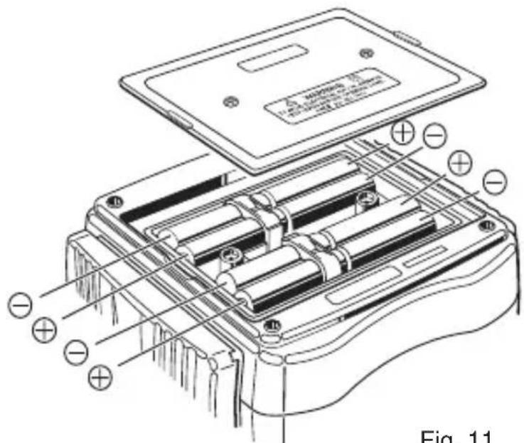
Fig. 11
10. Strap Belt Assembly
Correct assembly is shown in Fig.12. By hanging the instrument round the neck, both hand let free for testing.
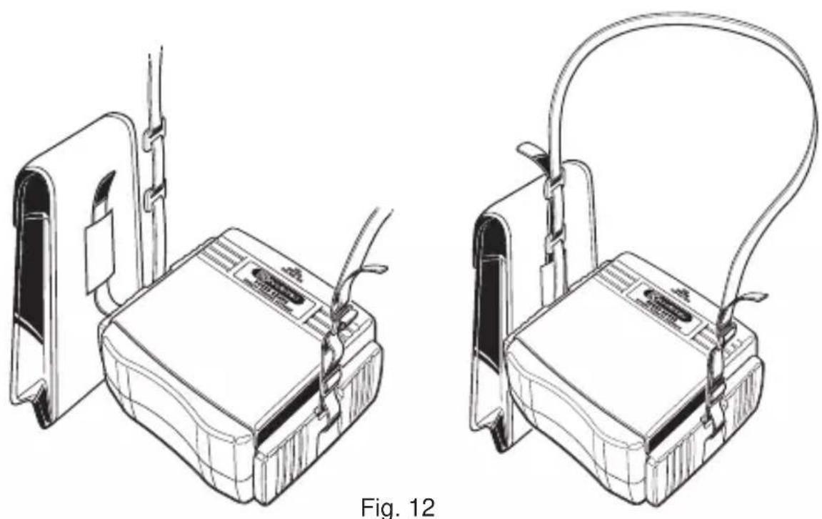
Pass the Strap belt down through the side panel of the main body from the top, and up through the slots of the Probe case from the bottom.
Pass the Strap through the buckle, adjust the strap for length and secure.
DISTRIBUTOR
9-1892-1900C
Kyoritsureservestherightstochangespecificationsordesigns describedinthismanualwithoutnoticeandwithoutobligations.

natural_image
Abstract black arrow symbol pointing left within a rectangular frame (no text or numbers)Factory: Ehime, Japan
www.kew-ltd.co.jp
- SafetyWarnings
- ⚠ WARNING
- ⚠️ DANGER
- WARNING
- CAUTION
- Symbols used on the instrument
- Procedure of removing Cover
- 2-1 Method of removing the Cover
- 2-2 Method of storing the Cover
- 3.Feature
- Specification
- ● Measuring range and accuracy
- ● Applied standards
- ● Display
- - Operating error
- Instrument Layout
- Test lead with alligator clip M7129A
- Protective figerguard :
- \* Long pin for M7128
- Measurement principle
- Preparation
- 7-1 Connection of Test Leads
- 7-2 Setting of Measurement Range
- 7-3 Setting of IΔn
- 7-4 Setting of Test Polarity
- 7-5 Backlight
- Measurements
- 8-1 Connection
- 8-2 Voltage Measurement
- 8-3 RCD test
- 8-4 Remote Test
- DANGER
- ● Neutral - Line
- ! DANGER
- ● Line - Line
- 8-5 Operating time
- Battery Replacement
- Strap Belt Assembly
Brand : Kyoritsu
Model : KEW 5410
Category : Measurement