LKZ-1000 - Detector Sonel - Free user manual and instructions
Find the device manual for free LKZ-1000 Sonel in PDF.


| Product Type | Cable & Pipe Locator (Detector) |
| Model | LKZ-1000 (Locator LKO-1000) |
| Weight | 2.7 kg (6 lbs) including batteries |
| Power Supply | 6 x LR6 (AA) alkaline batteries |
| Battery Life | Approximately 40 hours intermittent use at 20°C |
| Operating Modes | Power, Radio, 8 kHz, 33 kHz, Auto (Power + Radio) |
| Depth Range (Power/Transmitter Mode) | Up to 3 m (10 ft) |
| Depth Accuracy | ±10% of depth (0.3 to 3.0 m range) |
| Frequency Ranges | Power: 50/60 Hz; Radio: 15-60 kHz; Active: 8.192 kHz, 32.768 kHz |
| Display | 48-segment bar graph, backlit LCD with mode and depth indicators |
| Audio Output | Dual speakers, 85 dBA at 30 cm, different tones per mode |
| Hazard Zone Alarm | Additional warning for close proximity of services in Power, 8 kHz, 33 kHz, Auto modes |
| Peak Hold | Adjustable 0-5 seconds for pinpointing |
| Environmental Protection | IP54 (dust-protected, splash-proof) |
| Operating Temperature | -20°C to +50°C (-4°F to +122°F) |
| Storage Temperature | -40°C to +70°C (-40°F to +158°F) |
| Humidity | 95% RH non-condensing |
| Bluetooth (optional) | Class 2, up to 30 m range |
| Memory Capacity | 32 MB |
| Maintenance | Clean and dry at <40°C; keep plugs clean; replace batteries when low; periodic calibration every 12 months |
| Spare Parts / Repair | Replaceable battery hatch, case foot; service by authorized Sonel workshop; use only alkaline batteries |
| Safety | Hazard zone alarm; warnings for live services; depth compensation required for large diameter pipes; use with caution near electrical lines |
| Included Accessories | Locator LKO-1000, transmitter LKN-1000, case L-6, earth contact pin probe |
| Compliance | FCC Part 15, European R&TTE Directive 1999/5/EC (Class 1) |
Frequently Asked Questions - LKZ-1000 Sonel
User questions about LKZ-1000 Sonel
0 question about this device. Answer the ones you know or ask your own.
Ask a new question about this device
Download the instructions for your Detector in PDF format for free! Find your manual LKZ-1000 - Sonel and take your electronic device back in hand. On this page are published all the documents necessary for the use of your device. LKZ-1000 by Sonel.
USER MANUAL LKZ-1000 Sonel
Cable & Pipe Locator LKZ-1000
v2.4 10.07.2023
USER MANUAL
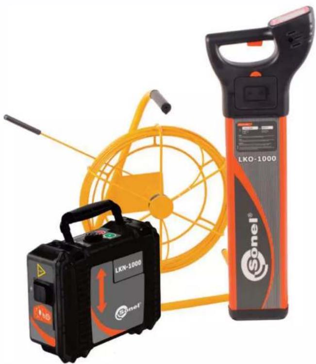
natural_image
Exterior view of a LKN-1000 and Sonel detector with orange coil and orange arm (no text or symbols on main objects)Introduction
Purchase
Congratulations on your purchase of a LKZ-1000 instrument


Product identification
This manual contains important safety directions as well as instructions for setting up the product and operating it. Refer to "9 Safety Directions" for further information. Read carefully through the User Manual before you switch on the product.
The serial numbers of your products are indicated on the type plate. Enter the serial numbers in your manual and always refer to this information when you need to contact your agency or Sonel S.A. authorised service workshop.
Serial No. LKO-1000:
LKN-1000:
Conductive Rod:
Signal Clamp N-2:
Connection Set AS-1:
Sonde NAD-1: ____
Symbols
The symbols used in this manual have the following meanings:
| Type Description | ||
 | Danger | Indicates an imminently hazardous situation which, if not avoided, will result in death or serious injury. |
 | Warning | Indicates a potentially hazardous situation or an unintended use which, if not avoided, could result in death or serious injury. |
 | Caution | Indicates a potentially hazardous situation or an unintended use which, if not avoided, may result in minor or moderate injury and/or appreciable material, financial and environmental damage. |
 | Important paragraphs which must be adhered to in practice as they enable the product to be used in a technically correct and efficient manner. | |
Validity of this manual
This manual applies to Sonel locator and transmitter instruments LKO-1000 and LKN-1000 and accessories. Differences between the various instruments and models are marked and described.
Table of Contents
| In this manual | 1 General Information 7 | |
| 1.1 How to Use this Manual 7 | ||
| 1.2 General Information 8 | ||
| 1.3 Instruments and Accessories 10 | ||
| 2 How to Use the Locator 11 | ||
| 2.1 General Information 11 | ||
| 2.2 Locator Overview 12 | ||
| 2.3 Locator Setup and Information 14 | ||
| 2.4 Hazard Zone 16 | ||
| 2.5 How to Locate a Service 18 | ||
| 3 How to Use the Transmitter 30 | ||
| 3.1 General information 30 | ||
| 3.2 Transmitter Overview | 31 | |
| 3.3 How to Locate a Service Using the Transmitter | 33 | |
| 4 How to Use the Conductive Rod | 37 | |
| 4.1 General Information | 37 | |
| 4.2 Conductive Rod Overview | 37 | |
| 4.3 How to Locate a Service Using the Conductive Rod | 38 | |
5 How to Use the Signal Clamp 40
5.1 General Information 40
5.2 Signal Clamp Overview 40
5.3 How to Locate a Service Using the Signal Clamp 41
6 How to Use the Property Connection Set 43
6.1 General Information 43
6.2 Property Connection Set Overview 43
6.3 How to Locate a Service Using the Property Connection Set 44
7 How to Use the Sonde 46
7.1 General Information 46
7.2 Sonde Overview 46
7.3 How to Locate a Service Using the Sonde 49
8 Care and Transport 51
8.1 Transport 51
8.2 Storage 51
8.3 Cleaning and Drying 52
9 Technical Data 53
9.1 Locator Technical Data 53
9.2 Transmitter Technical Data 57
9.3 Conductive Rod Technical Data 60
9.4 Sonde Technical Data 62
9.5 Property Connection Set Technical Data 64
9.6 Signal Clamp Technical Data 66
Appendix A Functional Checks 69
A.1 Locator Functional Check 69
A.2 Transmitter Functional Check 73
A.3 Conductive Rod Functional Check 78
A.4 Sonde Functional Check 80
Appendix B World Frequency Zones 83
1. General Information
1.1 How to use this manual

Index
Instrument label
It is recommended to set up the product while reading through this manual.
The index is at the back of the manual.
On the Locator and Transmitter you will find a label that shows some important information by means of illustrations. You will find some of these illustrations in this manual too. This should help to get a clear connection between the instrument label and the information in this manual.
1.2 Sonel - General Information
Description
Locators are used to detect buried conductive services emitting an electromagnetic signal which is generated by a current passing through the service.
Transmitters are used to apply a distinct signal to conductive services, which may not radiate electromagnetic signals or may need to be traced for a specific purpose. The Transmitter is required to make a depth measurement.
The Locators and Transmitters described within this manual will greatly increase the detection process and help to reduce the dangers and costs associated with service strikes. But the very nature of electromagnetic location is dependent on the services being conductive (metallic) and radiating a signal as current flows through them.
It is important to remember that a Locator on its own will not detect all services and care should be taken when excavating. It is generally accepted that a safe system of work should be adopted which would include planning the work in advance, the use of utility maps, the use of Locators and Transmitters, and the use of safe digging practices.

Caution
The absence of a positive indication does not guarantee the non-existence of a service. Services without a detectable signal may be present.
The Locators can only locate non-metallic services such as plastic pipes, typically used by the water and gas utilities, with the use of appropriate accessories.
Precautions:
Always excavate with care.
Accessories
Designed to increase the detection of services with no (or little) signals on them. Generally work in conjunction with the Locator and Transmitter.
Functional Check
Designed to demonstrate the equipment is working satisfactorily in between service intervals. Refer to "Appendix A Functional Checks" for more information.
1.3 Instruments and Accessories
General information
This is a collection of products used to locate buried metallic and nonmetallic services.
a) Locator LKO-1000
(WMGBLKO1000)
b) Transmitter LKN-1000
(WMGBLKN1000)
c) Case L-6
(WAFUTL6)
d) Earth contact pin probe
(WASONG15)
Instruments Overview
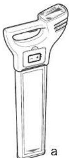
natural_image
Line drawing of a handheld electronic device with a rectangular body and handle (no text or symbols)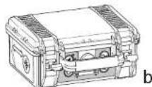
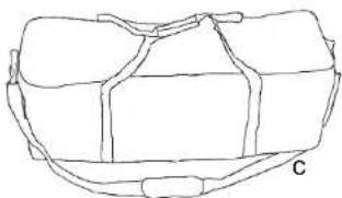
natural_image
Line drawing of a rectangular object with internal bands and a labeled point C (no text or symbols on the object itself)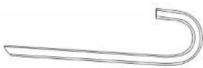
d
Accessories Overview
natural_image
Technical line drawing of a mechanical device with a central rotating wheel and a separate inset showing a labeled component (a) and 'b' (no text or symbols on the diagram itself)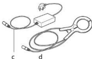
natural_image
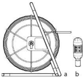
Diagram of a medical or laboratory setup with labeled parts (c and d), no readable text or symbols present.a) Conductive Rod (non metallic service tracer):
-30m (WAPRZPN30)
-50m (WAPRZPN50)
-80m (WAPRZPN80)
b) Sonde NAD-1 (WASONNAD1)
c) Property Connection Set AS-1
Europe („French“) standard(WAADAAS1PL)
Switzerland standard (WAADAAS1CH)
US standard (WAADAAS1US)
Australia standard (WAADAAS1AU)
d) Signal Clamp N-2 (WACEGN2)
2. How to Use the Locator
2.1 General Information
| Operating Modes | Passive modes (Power and Radio)Active modes (8kHz and 33kHz)Auto mode (Combined Power and Radio modes) |
| Electromagnetic signals | An electromagnetic signal radiates from buried conductive services as an electrical current flows through them. The Locator processes these signals and displays their presence. |
| Passive signals | Some signals are already present on buried services and can be readily detected by the Locator. We call these passive signals. These signals are generated by power distribution systems and radio transmitters. |
| Active tracing | Some conductive services do not emit passive signals. These services may be traced by applying a signal to the service by using a transmitter. |
| Depth indication | Depth indication is only available with the Locator when used in conjunction with the Transmitter or Sonde. The displayed depth is to the centre of the service or to the Sonde. |
| Hazard zone | Provides an additional alarm, indicating the close proximity of a service emitting a Power, 8kHz or 33kHz signal. |
| Peak hold | Assists in pinpointing a service by displaying the peak reading for a short period of time. |
2.2 LKO-1000 Locator Overview
Locator main parts
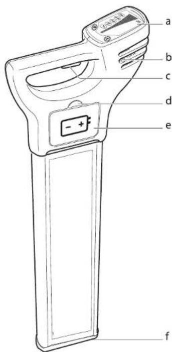
a) Display Panel
Contains the operational controls.
b) Speakers (mounted internally left and right)
Active at power on and when a signal is detected.
c) On/Off Trigger
Press and hold the trigger to activate the Locator.
Release the trigger to deactivate.
d) Battery Hatch Release
Pressing the yellow release button unlocks the battery hatch allowing access to the battery compartment.
e) Battery Compartment
6 x LR6 (AA) alkaline batteries are used. Replace all batteries when indicated.
f) Case Foot

The case foot can be replaced if it is worn. Contact your agency or Sonel S.A. authorised service workshop.
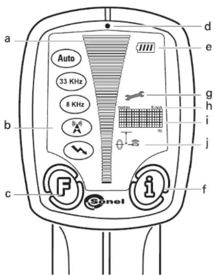
Display panel overview
a) Signal Strength Indicator
Indicates the response of the Locator to a signal (service).
b) Mode Indicators
Displays the selected mode: Power, Radio, 8kHz, 33kHz, Auto (as shown, from bottom to top).
c) Function Button
Selects operating mode.
d) Light Sensor
Automatically switches the displays backlight on or off to suit light conditions.
e) Battery Indicator
Indicates the battery condition. Segment illumina-tion decreases as battery condition declines. Replace the batteries when the battery indicator is empty.
f) „i” Button
Used to access the user settings and to provide a depth readout.
g) Wrench
Indicates that the Locator requires periodic service.
It is recommended to perform periodic calibration of the device every 12 months.
h) Measurement Unit
Indicates depth indication is in metric or feet and inches.
i) Display Readout
Alpha numeric matrix indicates system set up and depth indication.
j) Depth Mode Indicators
Indicates a depth reading to a service or a Sonde. Service depth icon used to indicate 'Hazard Zone' status.
2.3 Locator Setup and Information
The Locators offer a range of settings which the operator can adjust to their own preference. It also displays additional service and contact information as detailed
| Setting Description | |
| EST | Performs a function check on the locators hardware and software, displaying PAS if the Locator is within predefined tolerance or ERR if the locator it is not. |
| H.Z Switches ‘Hazard Zone’ on or off. | |
| VOL Adjust volume level (0 - 10). | |
| HLD Adjust peak hold duration (0 - 5 seconds). | |
| SSI Displays a numeric signal strength indicator. | |
| CST Adjusts display’s contrast (0 - 15). | |
| M/I Displays unit of measurement. | |
| CAL Displays the next service date DD/MM/YY. | |
| TEL Displays supplier/company telephone number. | |
| I.D. Displays the operator’s name. | |
| PWR | Displays the power mode regional setting. Refer to "Appendix B World Frequency Zones" for more information. |
| SR# Displays unit serial number. | |
| VER Displays software version | |
| CLK Displays the date held within the locators memory. Format DD/MM/YY/HH/MM/SS | |
| Accessing and adjusting the settings | 1. Switch the Locator on.2. Ensure the Locator is in Power mode. If required, press Function Button to select mode.3. Depress „i” Button for 2 seconds. The user settings will be displayed in the display readout.4. Press Function Button to toggle through to desired setting.5. Press „i” Button to select the setting.6. Press Function Button to activate/adjust.7. Press „i” Button to store and exit. | |
| Danger | The Locator may fail to detect electrical services in Power mode if an incorrect power setting is used.Precautions:Before use, verify the Locator is setup to be compatible with mains frequency supply in your country. Options are 50 or 60Hz. Refer to Appendix B „World Frequency Zones" for more information.Contact your agency or Sonel S.A. authorised service workshop if your unit is incorrectly configured for your region. | |
| Changing the battery | 1. Replace or recharge the batteries when the battery status indicator is empty.2. Press the release button to unlock the Battery Hatch. Remove the battery holder from the Locator.3. Replace all batteries with six new LR6(AA) batteries, or remove and recharge the battery pack if rechargeable batteries are fitted. | 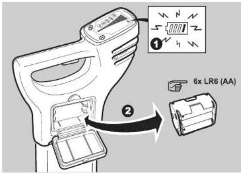 |
 | Alkaline batteries should be used. | |
SONEL Locator & Transmitter, How to Use the Locator 15
2.4 Hazard Zone
Description
Provides an additional warning to the close proximity of buried services and functions in the following modes:
- Power
• 8 kHz
• 33 kHz
• Auto mode (Power mode only)
Hazard zone status indicators
| Status Indicator Description | |
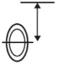 | Hazard zone is switched on. |
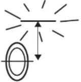 | Hazard zone on and is alarming. |
 | Hazard zone is switched off. |

Caution
The absence of a positive indication does not guarantee the non-existence of a service. Services without a detectable signal may be present. The Locators can only locate non-metallic services such as plastic pipes, typically used by the water and gas utilities, with the use of appropriate accessories.
Precautions:
Always excavate with care.
2.5 How to Locate a Service
Start up test
The following test sequence will take place every time the Locator is activated.
| On test Test pattern Info on label | ||
| Audio Output | On throughout test sequence | 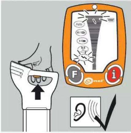 |
| Signal Strength indicator | Scrolls through in sequence once | |
| Mode indicators Briefly illuminated | ||
| Battery indicator On throughout | ||
| Measurement unit, display readout, depth mode indicator | Briefly illuminated | |
Locating process
The unit will then go into Power mode maximum sensitivity.
The locating process is split into three steps:
- Sweep Search
- Pinpointing the service
• Direction of the service
Sweep Search T
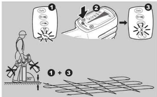
he unit will automatically select Power mode and maximum sensitivity
Auto mode combines the benefit of simultaneous detection in Power and Radio modes and helps to confirm the presence of services upon initial site occupation. Improved definition of the service will be provided by single mode operation.

- Define the area to be excavated.
- In Power mode cross the site from left to right keeping the Locator LKO-1000 upright, taking care not to swing the unit. Turn through 90 degrees and repeat.
Ensure that the Locator is held in an upright position and close to the ground. - Continue the sweep until either a signal is located or you are satisfied that the area has been adequately tested.
In the presence of a service emitting a traceable signal a tone will be emitted and the signal strength indicator will rise and fall as you pass over it. - Repeat the Sweep Search process in Radio mode.
The Sweep Search must be conducted in Power and Radio modes as a minimum, as not all services (including some electrical ones) emit a power signal. These services may be found using Radio mode or active modes.

Hazard zone can be operated in Power, 8kHz, 33kHz and Auto modes and provides an additional alarm to the presence of buried services which may be within close proximity.
Pinpointing the service
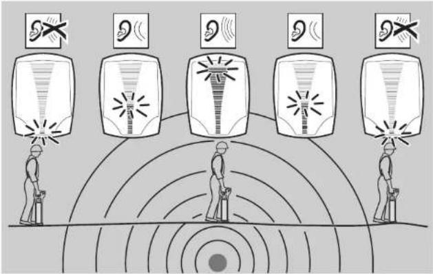
Retrace your steps to the area where the highest signal reading (peak response) was obtained. The service is directly below the Locator when the signal strength indicator is at its maximum. The audio output will automatically adjust to facilitate pinpointing over the service, and automati-cally reset when the signal strength indicator drops to its minimum position.

• Always use chalk or paint to mark services, never pegs.
- The signal strength indicator does not indicate the size, depth or type of a service.
Peak hold
When activated peak hold will show the highest peak reading obtained during the pinpoint process. The displayed reading can be adjusted between 0 to 5 seconds.
Detecting direction of the service
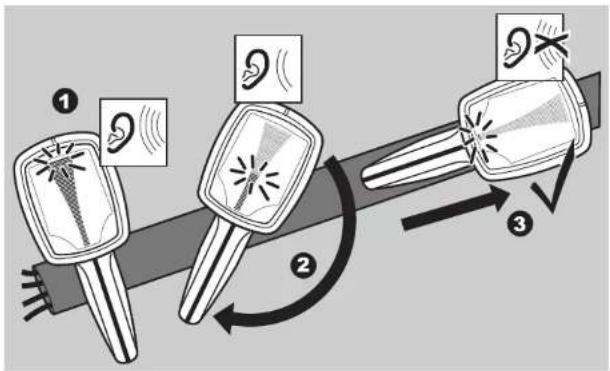
- Position the Locator directly over the service.
- Rotate the Locator on its axis.
- The blade of the Locator will be in line with the service when the signal strength indicator is at its minimum.
Depth Indication
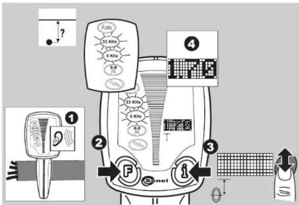
- Apply a signal to the service. Refer to Chapter 3 "How to Use the Transmitter" for more information.
- Select either 33kHz or 8kHz modes to suit the the Transmitter's output. Position the Locator directly over, and at 90 degrees to the direction of the service.
- Press and release the i Button.
- The display readout will indicate the depth of the service and the Line mode icon will be displayed.

- Activating Sonde depth will provide an inaccurate readout.
• Always use chalk or paint to mark services, never pegs or other material which are driven into the ground.
• Additional services may be within the excavation zone, as well as the service you are taking a depth reading from. - The reading will be more accurate when taken over a straight run, where the service does not bend, or have a service crossing it or coming off it.
- An additional depth reading should be taken with the locator lifted off the ground by approximately 100 mm (4 inches). The reading obtained should confirm the addition of this height.
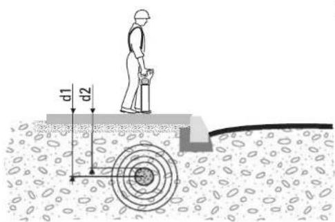
Depth shown and actual depth:
d1 Depth shown on the Sonel = depth to the centre of the line.
d2 Actual depth of the service.
Note the difference between d1 and d2!

Warning
The depth reading might not reflect the real depth if your Locator picks up the signal induced into the service by the Transmitter. This signal is radiated from the centre of the service.
This is even more important when the signal is produced by a Sonde, lying in a large diameter conduit!
Precautions:
Always compensate depth reading for service size.
Measuring Sonde depth
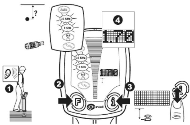
1 Switch on the sonde and set to the required frequency. Refer to Chapter 7 "How to Use the Sonde" for more information.
2. Select either 33kHz or 8kHz mode to suit the Sonde's output. Position the Locator directly over, and in line with the Sonde. Refer to Chapter 7 "How to Use the Sonde" for more information.
3. Press and hold down the iButton for 2 seconds until the dashed lines have scrolled through once.
4. The display readout will indicate the depth of the Sonde and the Sonde mode icon will be displayed.
-
An additional depth reading should be taken with the locator lifted off the ground by approximately 100 mm (4 inches). The reading obtained should confirm the addition of this height.
-
Activating line depth will provide an inaccurate readout.
• Always use chalk or paint to mark services, never pegs or other material which are driven into the ground.
• Additional services may be within the excavation zone, as well as the service you are taking a depth reading from.

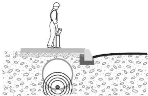
Depth shown and diameter:
natural_image
Illustration of a person standing on a platform with circular patterns and a central circular object (no text or symbols)Take special care when the signal is produced by a sonde, lying in a large diameter conduit!

Warning
The depth reading may not indicate the real depth of the service, especially if the sonde is lying at the base of a large diameter duct.
Precautions:
Always compensate depth reading for service size.
Depth code information
| Information code | Description | Information on instrument label | |
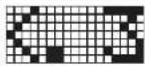 | metres | The service is too shallow to register properly. | 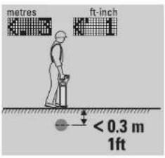 |
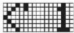 | ft-inch | ||
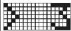 | metres | The service is too deep. | 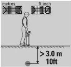 |
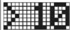 | ft-inch | ||
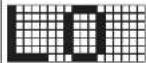 | The signal received by the Locator is too small to register properly. | 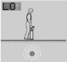 | |
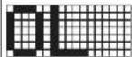 | The signal received by the Locator is too large to register properly. | 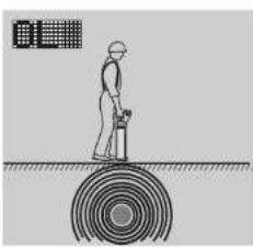 | |
| Information code | Description | Information on instrument label |
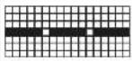 | Depth function not available. The Locator is set to the wrong mode for a depth reading to be taken. | 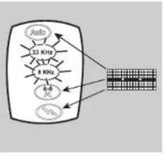 |
SONEL Locator & Transmitter, How to Use the Locator 27
3. How to Use the Transmitter LKN-1000
3.1 General Information
| Tracing signal | The Transmitter applies an electrical current signal onto a buried metallic service, which enables the service to be traced and identified by the Locator operating in the same mode. |
| Operating mode | There are three operating modes for onsite flexibility:8kHz for congested site operation33kHz for general usageCombined 8kHz and 33kHz available in Connection mode, enabling rapid selection and convenience on congested sites. The Locator can be used in either mode. |
| Description | Active tracing is a term frequently used when a Transmitter is used to apply a signal to a service enabling it to be traced. The use of a Transmitter will greatly improve the detection of services especially ones which may not have a signal on them.The signal from the Transmitter can be applied to services in two ways:Induction mode (8kHz or 33kHz):Induction is a quick and simple way to apply a signal to a service without the need to make any physical connection to it. The Transmitter uses an internal aerial to transmit the signal, therefore it should be noted that the signal will apply itself to additional services within close proximity to the Transmitter.Connection mode (8kHz or 33 kHz or combined 8kHz and 33kHz):This is the most efficient way of applying a signal to a service, and should be used whenever possible. The Transmitter's cable set or any of the available accessories are connected to the service which is to be traced or identified.8kHz is less likely to apply itself to additional services making tracing in areas of multiple services easier.33kHz is suitable for general site use.Combined 8 and 33kHz (Connection mode only) is useful in congested areas when either 8 or 33kHz may provide a better result. The best results can be simply achieved by switching modes on the Locator. |
 |
3.2 Transmitter Overview
Transmitter LKN-1000 main parts
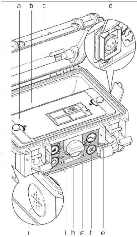
a) Battery Cover
b) Accessory Compartment
c) Earth Pin
d) Connection Socket
Used to connect accessories directly to metallic services. (Standard: crocodile clip cable set.)
e) Frequency Control and Indicator
Used to set the Transmitters frequency output.
LED illuminates to indicate selection.
f) Mute Control
Used to silence the Transmitter.
g) Mode Display
Indicates which mode is selected; Induction or Connection
h) Power Output Control and Indicator
Press the control to set the Transmitters power output.
Level 1, minimum power output indicated by the bottom LED illuminated.
Level 4, maximum power output indicated by all LED's illuminated. Default setting Level two.
i) On - Off control
Press to switch the transmitter on and off.
j) Speaker
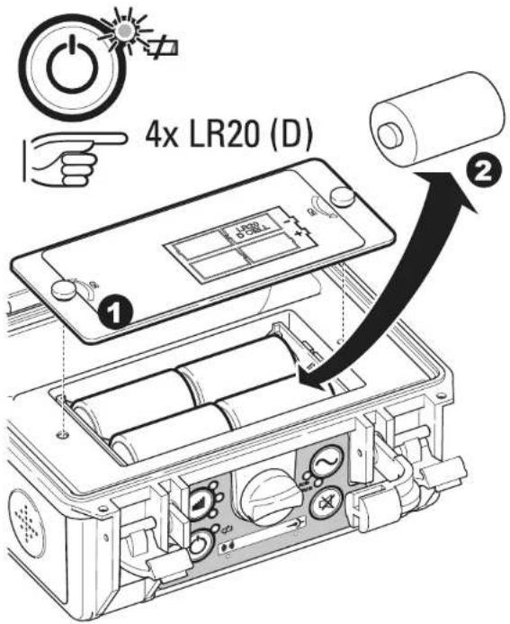
Changing the battery
The battery indicator flashes to indicate a poor battery condition.
- Unscrew the two fasteners and remove the cover.
- Replace all batteries with four new LR20 (D) type alkaline batteries, or remove and recharge the battery pack if rechargeable batteries are fitted.

Risk of electric shock when removing the Transmitter's battery pack.
Precautions:
Before removing the battery pack switch the transmitter off and remove any cable set or accessories from the connection socket.
3.3 How to Locate a Service Using the Transmitter LKN-1000
Start up test
The following test sequence will take place every time the Transmitter is activated.
| On test Test pattern | |
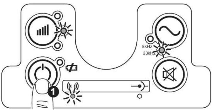 | |
| Audio output On throughout test sequence. | |
| LEDs LEDs are all lit throughout the test sequence | |
| Default mode selection | 33 kHz and power output level two is automatically selected. Induction mode is selected unless the Transmitter's cable set or accessories are connected. |
Using the Transmitter in Induction mode
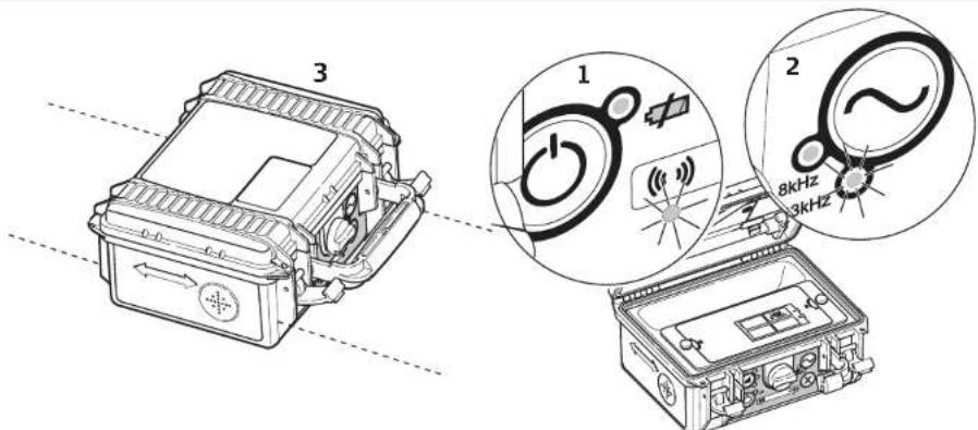

- Switch the Transmitter on, observe the Induction mode LED is illuminated and the battery level is adequate. Change batteries when indicated.
- Select the required power output level and frequency output.
- Place the Transmitter over the service with the arrows running in line with the suspected direction of the service.
- The tracing signal is induced directly onto the service from the internal aerial.
- Trace the suspected path of the service using the Locator set to the same frequency. Refer to Chapter 2 "How to Use the Locator" for more information.
- Work at least 10m / 33ft away from the Transmitter to avoid airborne signals. Reposition the Transmitter if required.
• Coupling efficiency is best at 33kHz. - The signal will couple to adjacent services dependent on depth and direction.
- Reducing the signal output can help to increase the battery life and the Transmitter is less likely to apply a signal to an adjacent service.
Using the Transmitter in Induction mode
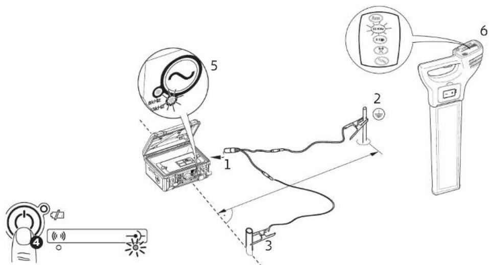
- Plug the Transmitter's cable set into the connection socket.
- Connect the black cable to the Earth Pin, ensuring that no services are below push the Earth Pin into the ground.
- Connect the red cable to the service.
- Switch the Transmitter on, observe the Connection mode LED is illuminated and the battery level is adequate. Change batteries when indicated.
- Select the required power output level and frequency output. A good level of tracing signal is indicated when the power output LED & audible tone changes from pulsed to continuous.
- Trace the signal using the Locator set to the same operating mode. Refer to Chapter 2 "How to use the Locator" for more information.

Danger

Warning

Warning

Connecting the cable set to a live service can result in an electric shock.
Precautions:
The connection cable set should never be connected directly to a live service.
The transmitter is capable of outputting potentially lethal voltages.
Precautions:
Care should be taken when handling exposed or non-insulated connections including;
the connection cables sets, the Earth Pin and the connection to the service.
Notify others who may be working on or around the service.
The transmitter is capable of outputting potentially lethal voltages.
Precautions:
Care should be taken when using the maximum power output level.
- Ensure there are no services below the ground when using the earth pin. Use the Locator in advance.
- The black cable can be connected to other metallic structures which go into the ground.
- In dry conditions it may be necessary to add water around the earth point to get a good connection.
- Examine connection points and remove contamination if a continuous audible output is not achieved.
- An extension cable is available to extend the red or black cable sets.
4. How to Use the Conductive Rods: 30 meters (WAPRZPN30), 50 meters (WAPRZPN50) or 80 meters (WAPRZPN80)
4.1 General Information
Description
The Conductive Rod is a service tracer enabling small diameter non-conductive pipes or ducts to be traced. It can be used in Line mode or Sonde mode.
4.1 Conductive Rod Overview
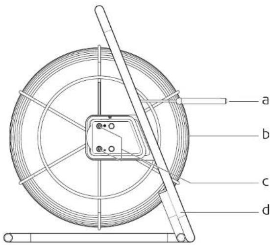
a) End of Coil: Sonde mode Used to accurately pinpoint the end point of the rod.
b) Rod: Line mode Flexible, Glass Fibre sheathed, which incorporates copper wires to conduct the signal.
c) Signal connection socket Used to connect to the Transmitter.
d) Frame Houses the flexible rod. Can be used in both vertical (shown) and horizontal orientation.
4.3 How to Locate a Service Using the Conductive Rod
Using the Conductive Rod in Line mode
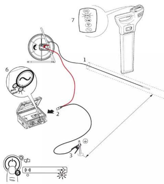
- Insert the rod into the pipe, duct, conduit or drain until the desired length is in place.
- Plug the Transmitter's cable set into the connection socket
- Connect the black cable to the Earth Pin, ensuring that no services are below push the Earth Pin into the ground
- Connect the red cable to the positive (+) terminal on the conductive rod.
- Switch the Transmitter on, observe the Connection mode LED is illuminated and the battery level is adequate. Change batteries when indicated.
- Select the required power output level and frequency output. A good level of tracing signal is indicated when the power output LED & audible tone changes from pulsed to continuous
- Trace the length of the rod using the Locator set to the same frequency.

- Ensure there are no services below the ground when using the earth pin. Use the Locato r in advance.
- At least half the Conductive Rod needs to be uncoiled when in use.
Using the Conductive Rod in Sonde mode
-
Insert the rod into the pipe, duct, conduit or drain until the desired length is in place.
-
Plug the Transmitter's cable set into the connection socket. Connect the red cable to the positive (+) terminal on the conductive rod, connect the black cable to the negative (-) terminal.
-
Switch the Transmitter on and select the required power output level and frequen cy output. A good level of tracing signal is indicated when the power output LED & audible tone changes from pulsed to continuous. The signal applies itself along the length of the Conductive Rod.
-
Trace the length of the rod using the Locator set to the same frequency.

- At least half the Conductive Rod needs to be uncoiled when in use.
5. How to Use the Signal Clamp N-2
5.1 General Information
Description
The Signal Clamp N-2 provides a safe technique of applying a signal to services such as telecom cables, etc. It is connected to the Transmitter and then clipped around the service. Supply is not interrupted by the applied signal.
5.2 Signal Clamp N-2 Overview
Signal Clamp main parts
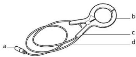
a) Transmitter plug connector
b) Jaws
c) Handle
d) Cable
5.3 How to Locate a Service Using the Signal Clamp
Using the Signal Clamp
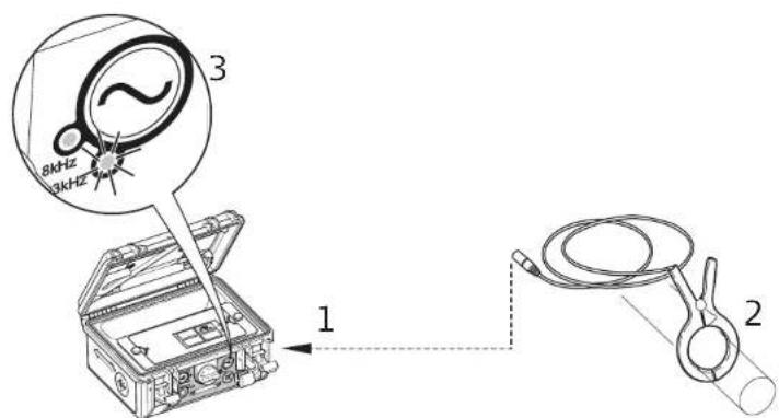
- Connect the Signal Clamp to the Transmitter.
- Open the jaws of the Signal Clamp and place around the service to be traced.
- Switch the Transmitter on and select the required power output level, set the frequency output to correspond with the clamp. A good level of tracing signal is indicated when the audible tone and power output LED are continuous.
- Trace the length of the service using the Locator set to the same frequency.


- Ensure the clamp jaws are fully engaged.
- Works best in 33kHz mode.
A hazardous signal may be present on the connection plug of the Signal Clamp when clipped over a live service.
Precautions:
The clamp should be connected to the Transmitter before clamping around a live service.

Danger A hazardous signal may be present on the service causing personal harm.
Precautions:
Do not use on electrical services which have impaired, or no insulation. If in doubt do not use.
6. How to Use the Property Connection Set AS-1
6.1 General Information
Description
The Property Connection Set provides a safe technique of applying a traceable signal to live electricity cables. It is connected to the service via a mains plug outlet and provides a traceable signal. Supply is not interrupted by the applied signal and the risk of serious injury is greatly reduced.
6.2 Property Connection Set Overview
Property Connection Set main parts
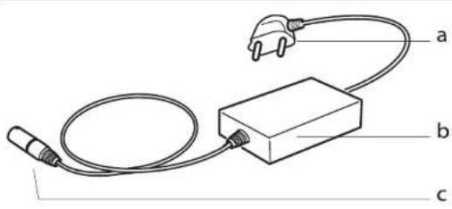
a) Mains plug connector
b) In line isolator
c) Transmitter plug connector
Available different plug connectors:
Europe („French“) standard WAADAAS1PL
Switzerland standard WAADAAS1CH
Australian standard WAADAAS1AU
US standard WAADAAS1US
UK standard WAADAAS1UK
6.3 How to Locate a Service Using the Property Connection Set
Using the Property Connection Set
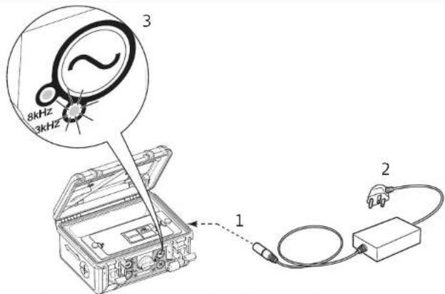
- Connect the Property Connection Set to the Transmitter.
- Connect the Property Connection Set to a live mains outlet. Ensure the switch on the mains is on.
- Switch the Transmitter on and select the required power output level, set the frequency output to correspond with the Property Connection Set. A good level of tracing signal is indicated when the audible tone and power output LED are continuous.
- Trace the length of the service using the Locator set to the same frequency.

- The mains supply must be live and switched on for correct operation.
- Ensure the Transmitter's frequency output is comparable to that of the Property Connection Set.
- Check the Property Connection Set type plate for the frequency rating.
• Works best with 33kHz.

Danger
A hazardous signal may be present on the connection plug of the Property Connection Set when connected to the mains supply.
Precautions:
The Property Connection Set should be connected to the Transmitter before connecting to the mains supply.

Danger
A hazardous signal may be present on the service or mains outlet causing personal harm. Precautions:
Do not use on electrical services which have impaired, or no insulation. If in doubt do not use.
7. How to Use the Sonde NAD-1
7.1 General Information
Description
The Sonde is a dual frequency signal transmitter used to trace drains, sewers and other non conductive services. It can be attached to a range of equipment including drain rods, boring tools and inspection cameras. It is powered by a 1.5V LR6 (AA) battery, so unlike other accessories this does not require a connection to the transmitter. The signal pattern transmitted from the Sonde is different to that which is radiated from a service; transmitting a peak signal over its main body, with a ghost signal at the front and back. This requires the Sonde to be traced with its own unique method. The i-Series Locators feature a numeric signal strength indicator (user setting SSI set to ON) which will greatly improve the locating process.

The numeric signal strength indicator is shown in the display readout on the Locator.
7.2 Sonde Overview
Sonde main parts
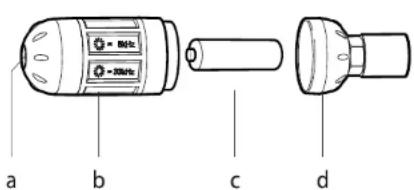
a) LED
b) Sonde body
c) LR6 (AA) battery
d) End cap and M10 connection point

The thread on the Sonde is a male M10, and comes with adaptors to both British and European drain rods.
Changing the frequency output
Changing to 33kHz mode:
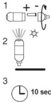
- Unscrew and remove end cap. Insert battery, positive end first. Refit end cap securely.
- Hold Sonde upright. Confirm green LED is continuous.
- Wait approximately 10 seconds for the green LED to start flashing.
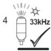
- With the green LED flashing, the Sonde is ready for use at 33kHz.
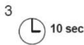
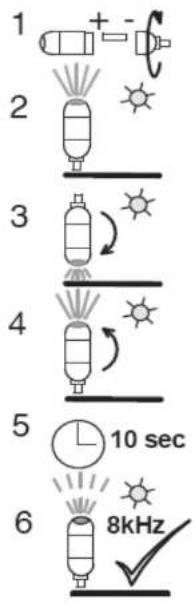
Changing to 8kHz mode:
-
Unscrew and remove end cap. Insert battery, positive end first. Refit end cap securely.
-
Hold Sonde upright. Confirm green light is continuous.
-
Rotate Sonde so the LED points down and wait approximately 1second.
-
Rotate Sonde upright. Confirm the amber coloured LED is continuous. If LED remains green repeat from step 1.
-
Wait approximately 10 seconds for the amber LED to start flashing.
-
With the amber LED flashing, the Sonde is ready for use at 8kHz.

Once the function of the Sonde has been checked with a Locator set to the same operating mode it can be attached to drain rods or other means of guiding it into the service being traced.
7.3 How to Locate a Service Using the Sonde
Locating the Sonde
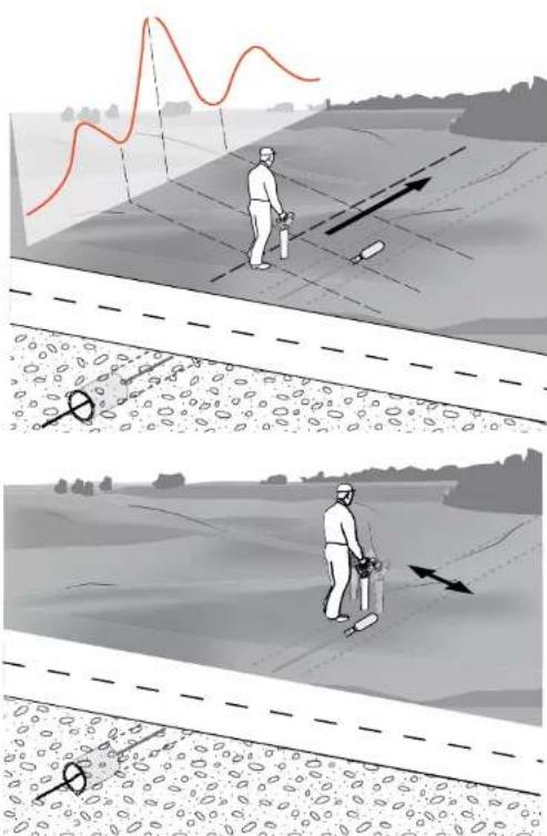
- Walk in line with the suspected direction of travel observing the display. The signal strength indicator will rise and fall as you pass over the ghost signal at the back of the Sonde, the peak signal directly over the Sonde and the ghost signal at the front. The numeric signal strength indicator will display its highest value when detecting the peak signal.
- Retrace your steps and position the locator directly over the peak signal. Move the locator left and right until the highest numeric reading is obtained. This reading will indicate the Sonde's precise location.
3. Depth indication
Depth indication can be used with a suitable depth locator. The locator must be positioned directly over the Sonde and in line with it (rotate the locator on its axis to find the highest reading). Press and hold the i Button for 2 seconds. The depth of the Sonde will be displayed in the depth readout window and the Sonde mode icon will be visible beneath the display.
- For ease and convenience mark the ground every 3 to 4 metres.
- For ease of use practice the process above ground
Tracing a "walk through" sewer
natural_image
Illustration of a person using a tool on a circular platform over water, with no visible text or symbols
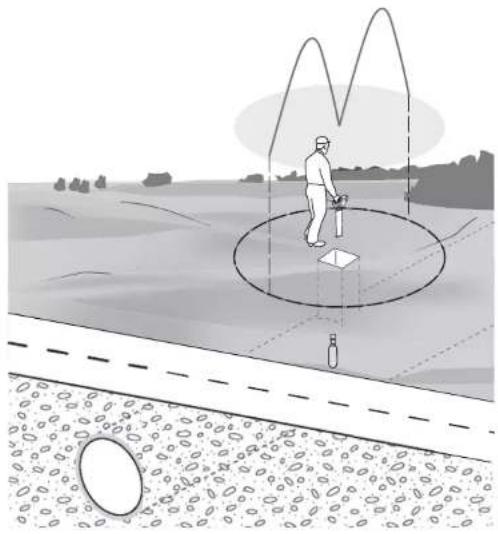
If a "walk through" sewer is being traced, another method is to place the Sonde vertically, for example to pinpoint a buried manhole. The Locator will pick up a pool of signal with a null point at the centre. This is an accurate method, but it is essential to ensure the Sonde is vertical.
8. Care and Transport
8.1 Transport
| Transport in the field | When transporting the equipment in the field, always make sure that you carry the product in its original transport container. |
| Transport in a road vehicle | Never carry the product loose in a road vehicle, as it can be affected by shock and vibration. Always carry the product in its transport container and secure it. |
| Shipping | When transporting the product by rail, air or sea, always use the complete original Sonel packaging, transport container and cardboard box, or its equivalent, to protect against shock and vibration. |
| Shipping, transport of batteries | When transporting or shipping batteries, the person in charge of the product must ensure that the applicable national and international rules and regulations are observed. Before transportation or shipping, contact your local passenger or freight transport company. |
| 8.2 Storage | |
| Product | Respect the temperature limits when storing the equipment, particularly in summer if the equipment is inside a vehicle. Refer to Chapter 10 "Technical Data" for information about temperature limits. |
| If the equipment is to be stored for a long time, remove the alkaline batteries from the product in order to avoid the danger of leakage. |
8.3 Cleaning and Drying
Dry the product, the transport container, the foam inserts and the accessories at a temperature not greater than 40^ C / 104^ F and clean them. Do not repack until everything is completely dry.
Keep plugs clean and dry. Blow away any dirt lodged in the plugs of the connecting cables.
9. Technical Data
9.1 Locator LKO-1000 Technical Data
Typical detection range
| Mode Distance along conductor | |
| Power Mode length of conductor | |
| Radio Mode length of conductor | |
| Conductive Rod Mode length of unwound rod |
Operating depth range
| Mode Range | |
| Power Mode to 3m / 10ft | |
| Radio Mode to 2m / 7ft | |
| Transmitter Mode to 3m / 10ft |
Typical depth accuracy
| 10% of depth in line or Sonde |
| 0.3 to 3.0m (1 to 10 ft) depth range |
Operating frequencies
| Mode Frequency | |
| Power Mode 50Hz or 60Hz | |
| Radio Mode 15kHz to 60kHz | |
| 8kHz Mode 8.192 (8) kHz |
Operating frequencies
| Mode Frequency | |
| 33kHz mode 32.768(33)kHz | |
| Auto mode Power mode and Radio mode |
Additional Extras
| Feature Specification | |
| Bluetooth (when fitted) Class 2, Nom 30metres | |
| Memory Capacity 32Mb |
Display Panel
| • 48 segment bar graph | • Bluetooth indicator |
| • 5 mode indicators | • Integrated backlight |
| • Battery status indicator | • Annual service indicator |
| • Line depth indicator | • 3 alpha numeric dot matrix displays 5x7 |
| • Sonde depth indicator |
Keypad
| 2 membrane push buttons |
| • Dual speakers:Audio volumes: 85 dBA @ 30 cmTone: Power, Radio and Auto mode: continuous tone (different pitch for each tone),8kHz and 33kHz mode: pulsed tone (different pitch for each tone). All five tones are different. |
| • Pneumatic headphone sockets are integrated |
Speakers
Internal battery
Type: 6 x LR6 (AA) alkaline
Typical operating time: 40hrs intermittent use at 20°C / 68°F; in 8kHz mode or 33kHz mode
Instrument dimensions
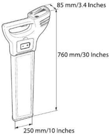
Weight
Instrument: 2.7kg / 6lbs
(including batteries)
Environmental specifications
| Type Description | ||
| Temperature Operating | Storage | -20°C to +50°C-4°F to +122°F-40°C to +70°C-40°F to +158°F |
| Protection against Water, Dust and Sand | IP54 (IEC 60529)Dust-protected | |
| Humidity 95% RH non condensing | The effects of condensation are to be effectively counteracted by periodically drying out the product. | |
Conformity to national regulations
• FCC Part 15 (applicable in US)
• Hereby, Sonel S.A. declares that the Locator LKO-1000 is in compliance with the essential requirements and other relevant provisions of Directive 1999/5/EC. Class 1 equipment according European Directive 1999/5/EC (R&TTE) can be placed on the market and be put into service without restrictions in any EEA member state.
- The conformity for countries with other national regulations not covered by the FCC part 15 or European directive 1999/5/EC has to be approved prior to use and operation.
Frequency band
50Hz to 60kHz
Output power
Receive only
9.2 Transmitter Technical Data LKN-1000
| Typical detection range | Mode Distance | |
| Induction mode 150m / 490ft | ||
| Connection mode 250m / 820ft | ||
| Operating transmission frequencies | • 8.192(8)kHz• 32.768(33)kHz | |
| Display panel | • 2 LED Mode Indicators• 2 LED Frequency Indicators• LED Battery Status Indicator• 3 LED Power Output Indicators | |
| Keypad | 4 membrane push buttons | |
| Integral Speakers | Audio volumes: 85 dBA @ 30 cmTone: 8kHz mode: Low pitched tone33kHz mode: Higher pitched toneInduction mode: Pulsed toneConnection mode: Pulsed tone when poor or no current output, continuous tone when good connection | |
| Internal battery | Type: 4 x LR20(D) alkaline, supplied; or recharcheable battery D typeTypical operating time: 30hrs intermittent use at 20°C / 68°F | |
Instrument dimensions
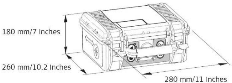
Weight
Instrument: 2.4kg / 5.3lbs (including batteries)
Environmental specifications
| Type Description | ||
| Temperature Operating | Storage | -20°C to +50°C-4°F to +122°F-40°C to +70°C-40°F to +158°F |
| Protection against Water, Dust and Sand | With cover open IP$4 (IEC 60529) Dust-protected | |
| With cover closed and secured | IP65 (IEC 60529)Dust tightWaterproof to 1m temporary immersion | |
| Humidity 95% RH non condensing. The effects ofcondensation are to be effectivelycounteracted by periodically drying out the product. | ||
Conformity to national regulations
• FCC Part 15 (applicable in US)
• Hereby, Sonel S.A. declares that the transmitter LKN-1000 is in compliance with the essential requirements and other relevant provisions of Directive 1999/5/EC. Class 1 equipment according European Directive 1999/5/EC (R&TTE) can be placed on the market and be put into service without restrictions in any EEA member state.
- The conformity for countries with other national regulations not covered by the FCC part 15 or European directive 1999/5/EC has to be approved prior to use and operation.
Output power
1W maximum, when directly connected to a buried service with a ground impedance of 100 Ohm or less.
9.3 Conductive Rods Technical Data
| Typical detection range | Both modes, Line and Sonde: Typical 3.0m / 10ft |
| Tracing distance | max: 30m/99ft (WAPRZPN30); 50m/165ft (WAPRZPN50); 80m/263ft (WAPRZPN80).Reel length dependant |
| Operating transmission frequencies | • 8.192(8)kHz or• 32.768(33)kHz |
| Instrument dimensions | 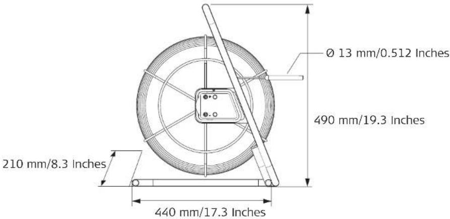 |
| Weight | Instrument: 7.3kg / 16.1lbs |
Environmental specifications
| Type Description | ||
| Temperature Operating | Storage | -20°C to +50°C-4°F to +122°F-40°C to +70°C-40°F to +158°F |
| Protection against Water, Dust and Sand | Frame IP54 (IEC 60) | 529)Dust-protected |
| Rod Fully submersible | ||
| Humidity 95% RH non condensingThe effects ofcondensation are to be effectivelycounteracted by periodically drying out the product. | ||
Conformity to national regulations
• FCC Part 15 (applicable in US)
• Hereby, Sonel S.A. declares that the Conductive Rod is in compliance with the essential requirements and other relevant provisions of Directive 1999/5/EC.
Class 1 equipment according European Directive 1999/5/EC (R&TTE) can be placed on the market and be put into service without restrictions in any EEA member state.

- The conformity for countries with other national regulations not covered by the FCC part 15 or European directive 1999/5/EC has to be approved prior to use and operation.
9.4 Sonde NAD-1 Technical Data
Operating transmission frequencies
• 8.192(8)kHz
• 32.768(33)kHz
Type: 1 x LR6 (AA) alkaline
Typical operating time: 40 hrs intermittent use at 20°C / 68°F; in 8 kHz mode or 33 kHz mode
Instrument dimensions
∅38 mm/1.5 Inches
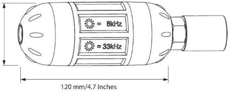
Weight
Instrument: 0.18 kg / 0.4 lbs (including batteries)
Environmental specifications
| Type Description | ||
| Temperature Operating | Storage | -20°C to +50°C-4°F to +122°F-40°C to +70°C-40°F to +158°F |
| Protection against Water, Dust and Sand | Fully submersible | |
| Humidity 95% RH non condensing | The effects of condensation are to be effectively counteracted by periodically drying out the product. | |
Conformity to national regulations
• FCC Part 15 (applicable in US)
• Hereby, Sonel S.A. declares that the Sonde is in compliance with the essential requirements and other relevant provisions of Directive 1999/5/EC.
Class 1 equipment according European Directive 1999/5/EC (R&TTE) can be placed on the market and be put into service without restrictions in any EEA member state.
- The conformity for countries with other national regulations not covered by the FCC part 15 or European directive 1999/5/EC has to be approved prior to use and operation.

9.5 Property Connection Set AS-1 Technical Data
Operating transmission frequencies
• 8.192(8)kHz
• 32.768(33)kHz
Instrument dimensions
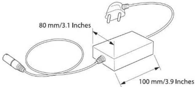
Weight
Instrument: 0.15 kg / 0.3 lbs
| Type Description | ||
| Temperature Operating | Storage | -20°C to +50°C-4°F to +122°F-40°C to +70°C-40°F to +158°F |
| Protection against Water, Dust and Sand | IP54 (IEC 60529)Dust-protected | |
| Humidity 95% RH non condensing | The effects of condensation are to be effectively counteracted by periodically drying out the product. | |
Conformity to national regulations
• FCC Part 15 (applicable in US)
- Hereby, Sonel S.A. declares that the Property Copnlection Set is in compliance with the
essential requirements and other relevant provisions of Directive 1999/5/EC. Class 1 equipment according European Directive 1999/5/EC (R&TTE) can be placed on the market and be put into service without restrictions in any EEA member state.
- The conformity for countries with other national regulations not covered by the FCC part 15 or European directive 1999/5/EC has to be approved prior to use and operation.

Available different plug connectors:
Europe („French“) standard WAADAAS1PL
Switzerland standard WAADAAS1CH
Australian standard WAADAAS1AU
US standard WAADAAS1US
UK standard WAADAAS1UK
9.6 Signal Clamp N-2 Technical Data
Operating transmission frequencies
32.768(33)kHz (recommended) when used with a signal transmitter set in 33kHz mode.
Instrument dimensions
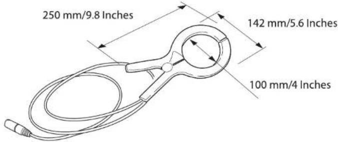
Weight
Instrument: 0.354kg / 0.76lbs
| Type Description | ||
| Temperature Operating | Storage | -20°C to +50°C-4°F to +122°F-40°C to +70°C-40°F to +158°F |
| Protection against Water, Dust and Sand | IP54 (IEC 60529)Dust-protected | |
| Humidity 95% RH non condensing | The effects of condensation are to be effectively counteracted by periodically drying out the product. | |
Conformity to national regulations
• FCC Part 15 (applicable in US)
- Hereby, Sonel S.A. declares that the Signal Clamp N-2 is in compliance with the essential
requirements and other relevant provisions of Directive 1999/5/EC.
Class 1 equipment according European Directive 1999/5/EC (R&TTE) can be placed on the market and be put into service without restrictions in any EEA member state.
- The conformity for countries with other national regulations not covered by the FCC part 15 or European directive 1999/5/EC has to be approved prior to use and operation.

Appendix A Functional Checks
A.1 Locator Functional Check
Checking the Function
Before any tests can be carried out it is vital to check the status of the unit, its batteries and basic functionality.
The following list is used to achieve this.
1. Inspection
- Casing The casing should be free of significant damage.
- Labels Body labels must be legible and intact. Display label must be free of damage and tears.
- Battery hatch The hatch must lock into place.
- Battery holder All the battery contacts and springs on the holder must be free of corrosion and the holder in good condition.
- Battery contacts The battery contacts must be free of corrosion.
Once the general condition of the Locator is established the Audio Visual test can be performed.
2. Audio / Visual display test
Upon depressing the trigger the Locator should test the display and speakers by illuminating each segment in the bar display, the mode and function indicators and depth display, the battery indicator light will illuminate throughout the display test. All LCDs must be operative and an audible output must be heard.
| 3. Battery / Functional self checkIf there is no response when the trigger is activated or the low battery illuminates (or flashes) after the Audio / Visual display test, the batteries will have to be replaced. Use alkaline batteries. Replace all of the batteries at the same time. | |
| Checking the Performance | The purpose of the following procedure is to verify the performance of the Locator. It is important that the test is conducted away from areas of electromagnetic interference or over buried services with a large signal radiating off them.1. Switch the Locator on.2. Whilst in Power mode hold down the i Button, until the settings are displayed.3. Using the Function Button toggle through the settings until EST is displayed.4. Press the i Button to activate the test.5. Observe the displayed output:PAS means unit is within set tolerances.ERR means unit is outside set tolerances and may need servicing |
| Checking depth indication | Repeat the test in a different location if the units displays ERR.The Locator will automatically repeat the function test if it fails.Repeated failure will indicate a faulty unit, which must be returned for service.This test can be carried out provided the depth of a service on the test area is known.1. Switch the Locator on and ensure that it is in 33kHz mode.2. Position the Locator directly over and at right angle to the service.3. Press and release the i Button to activate the depth measurement.4. Record the depth.If the depth reading deviates from the normal value or an error code is displayed, the Locator should be returned for service. |

Functional test check list
If any of these tests give no response or a significantly different response from normal, the Locator should be returned for service.
| Functional test check list | |||||
| Unit: Locator... | Serial Number: Comments: | ||||
| Test Operative Fail analysis Notes | |||||
| 1. Casing Return for repair/ | Replace | Casing should be free of damage. | |||
| 2. Labels Return for repair/ | Replace | Body labels must be legible and intact. Display label must be free of damage and tears. | |||
| 3. Battery hatch Return for repair/ | Replace | Hatches must be free of corrosion. | |||
| 4. Battery holder Replace Holder must be free of corrosion. | |||||
| 5. Battery contacts | Return for repair | Contacts must be free of corrosion. | |||
| 6. Audio/Visual display test | Return for repair | LCD is illuminated and an audible output must be heard. | |||
| 7. Batteries Replace Replace | place | alkaline batteries | if pack is exhausted (no response) or if the battery indicator light is illuminated or flashing after display test.Replace all batteries! | ||
| 8. Power mode Return for repair | repair Response width and peak | value similar to test unit. | |||
| 9. Radio mode Return for repair | repair Response width and peak | value similar to test unit. | |||
| 10. 8 kHz Return for repair | repair Response width and peak | value similar to test unit. | |||
| 11. 33 kHz Return for repair | repair Response width and peak | value similar to test unit. | |||
| 12. Depth Mode 8kHz and 33kHz | Return for repair Gives same result as test unit (10% accuracy). | ||||
| Tested by: Date: | |||||
A.2 Transmitter Functional Check
Checking the Function
The purpose of the following procedure is to verify the performance of the Signal Transmitter.
Before any tests can be carried out it is vital to check the status of the unit, its batteries and basic functionality.
To carry out this test the following are required:
- A Locator to detect the signals.
- A test area free of services as illustrated.
- Inspection
- Casing The casing should be free of significant damage.
- Labels Body labels must be legible and intact. Display label must be free of damage and tears.
- Battery hatch The hatch must lock into place.
- Battery holder All the battery contacts and springs on the holder must be free of corrosion and the holder in good condition.
- Battery contacts The battery contacts must be free of corrosion.
Once the general condition of the Transmitter is established the Audio Visual test can be performed.
- Audio / Visual display test
Turn on the Transmitter. The LED display will illuminate and the speakers will emit a tone, the battery/output level indicator will illuminate throughout the test. All LEDs must be operative and an audible output must be heard.
Checking the performance
3. Battery check
The battery indicator flashes to indicate a poor battery condition. Replace all batteries with four new LR20 (D) type alkaline batteries, or remove and recharge the battery pack if rechargeable batteries are fitted.
The purpose of the following procedure is to verify the performance of the Transmitter. It is important that the test is conducted away from areas of electromagnetic interference.
-
Plug the Transmitter's cable set into the connection socket.
-
Connect the black and red cable clips together, ensuring good metal to metal contact.
-
Hold down Frequency Control Button and switch the Transmitter on. Note, Hold the frequency control button down until the Extended Self Test has commenced.
-
Observe the displayed output:
Induction Mode Test Mode Display: Induction LED illuminated.
Frequency Display: Frequency LED illuminates showing the frequency on test.
Mode Display: Induction LED off.
Connection Mode Test Mode Display: Connection LED illuminated.
Frequency Display: Frequency LED's illuminates showing the frequency on test.
Mode Display: Connection LED off.
- The transmitter will display the outcome:
Pass Battery indicator: LED Flash (if tested with poor batteries).
Audible Output: High - Low pulsed tone emitted three times.
Fail Battery indicator: LED Flash (if tested with poor batteries).
Audible Output: Low pitch tone emitted.
Mode Display: Induction or Connection LED illuminated to show failure mode.
Frequency Display: Frequency LED illuminated to show frequency failure.


Warning
- If the unit fails check the Transmitter's cable set is fully engaged and the clips are connected.
- Repeated failure will indicate a faulty unit, which must be returned for service.
If any of these tests give no response or a significantly different response from normal, the Transmitter should be returned for service.
The transmitter is capable of outputting potentially lethal voltages.
Precautions:
Care should be taken when handling exposed or non-insulated connections including; the connection cables sets, the Earth Pin and the connection to the service.
Notify others who may be working on or around the service.
Functional test check list
| Functional test check list | |||||
| Unit:Transmitter... | Serial Number: Comments: | ||||
| Test Operative Fail analysis Notes | |||||
| 1. Casing Return for repair/ | Replace | Casing should be free of damage. | |||
| 2. Labels Return for repair/ | Replace | Body labels must be legible and intact. Display label must be free of damage and tears. | |||
| 3. Battery cover and accessory cover | Return for repair/Replace | Hatches must lock into place. | |||
| 4. Battery contacts Replace Contacts must be free of corrosion. | |||||
| 5. Audio/Visual display test | Return for repair All | LEDs must illuminate and an audible output must be heard. | |||
| 6. Batteries | Return for repair Replace alkaline batteries if exhausted (no response) or if the battery indicator light is illuminated or flashing after display test.Replace all batteries! | ||||
| 7. Induction mode Return for repair / | Replace | Reduced or no output signal. | |||
| 8. Connection mode; no change in audio indication | Return for repair / Replace | Faulty cable. | |||
| 9. Connection mode; no change in audio indication | Return for repair / Replace | No output signal. | |||
| Tested by: Date: | |||||
A.3 Conductive Rod Functional Check
Checking the Function
The purpose of the following procedure is to verify the performance of the Conductive Rod.
To carry out this test the following are required:
- A Transmitter for generating the signal in the Sonde and Line mode tests
- The cable set for the Conductive Rod.
Plug the Transmitter's cable set into the connection socket. Connect the red cable to the positive (+) terminal on the conductive rod, connect the black cable to the negative (-) terminal.
Switch the Transmitter on and adjust the power output on the Transmitter to minimum, the audible output must be constant. Disconnect the black cable from the negative (-) terminal, the audible output must be pulsed.

If any of these tests give no response or a significantly different response from normal, the Conductive Rod should be returned for service.
Functional test check list
| Functional test check list | |||||
| Unit:Conductive Rod... | Serial Number: | Comments: | |||
| Test Operative Fail analysis Notes | |||||
| 1. Sonde mode:Transmitter audio output does not go continuous | Return or replace cable set | Faulty cable. | |||
| 2. Sonde mode: Locator does not detect signal | Return for repair/Replace | One or both internal wires are open or short circuit. | |||
| 3. Line mode: Locator does not detect signal | Return for repair/Replace | One or both internal wires are open or short circuit. | |||
| Tested by: Date: | |||||
A.4 Sonde Functional Check
Checking the Function
The purpose of the following procedure is to enable a user to verify the performance of the Sonde.
To carry out this test the following are required:
• A Locator to detect the signal.
- A work area free of services as illustrated.
1. Inspection
- Casing The casing should be free of significant damage, with the sealing ring and the screw thread intact
Once the general condition of the Sonde is established the self test can then be used to indicate the basic unit function and state of the batteries.
2. LED test
Turn on the sonde, the led display will illuminate.
3. Battery check
A dull LED, and lack of detection range will indicate poor battery condition. Use alkaline batteries.
- Switch sonde on and activate 33kHz mode.
- Set Locator to 33kHz mode and aim at Sonde (see diagram).
- At 2m/6.56ft the Locator must be at maximum.
- Repeat this with Sonde and Locator in 8kHz.
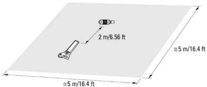

If any of these tests give no response or a significantly different response from normal, the Sonde should be returned for service.
Functional test check list
| Functional test check list | |||||
| Unit:Conductive Rod... | Serial Number: Comments: | ||||
| Test Operative Fail analysis Notes | |||||
| Yes | No N/A | ||||
| 1. Casing Fail Casing should be free of | damage. | ||||
| 2. Screw thread and seal | Fail Screw thread must be intact and seal in place. | ||||
| 3. Battery contacts Fail Contacts must be free of | corrosion.maximum display at 2metres. | ||||
| 4. 33 kHz mode Fail | LED must be illuminated brightly and pulse fast. Locator must provide maximum display at 2 metres. | ||||
| 5. 8 kHz mode Fail | LED must be illuminated brightly and pulse slowly. Locator must provide maximum display at 2metres. | ||||
| Tested by: Date: | |||||
Appendix B
World Frequency Zones
North America
Canada 120 V / 60 Hz
United States 120 V / 60 Hz
Mexico 120 V / 50 Hz, 60 Hz
Central America
Bahamas 115 V / 60 Hz
Barbados 115 V / 50 Hz
Belize 110-220 V / 60 Hz
Bermuda 115 V / 60 Hz
Costa Rica 120 V / 60 Hz
Cuba 115-120 V / 60 Hz
Dominican Republic 110-220 V / 60 Hz
El Salvador 120-240 V / 60 Hz
Guatemala 115-230 V / 60 Hz
Haiti 110-220 V / 60 Hz
Honduras 110-220 V / 60 Hz
Jamaica 220 V / 50 Hz
Netherland Antilles 110-127 V / 50 Hz
Nicaragua 120 V / 60 Hz
Panama 120 V / 60 Hz
Puerto Rico 120 V / 60 Hz
Trinidad & Tobago 115-230 V / 60 Hz
Virgin Islands 120 V / 60 Hz
South America
Argentina 230 V / 50 Hz
Bolivia 110 V / 50 Hz
Brazil 110-127-220 V / 60 Hz
Chile 220 V / 50 Hz
Colombia 110-220 V / 60 Hz
Ecuador 110-220 V / 60 Hz
French Guiana 220 V / 50 Hz
Guyana 110-240 V / 60 Hz
Paraguay 220 V / 60 Hz
Peru 220 V / 60 Hz
Surinam 110-127 V / 60 Hz
Uruguay 220 V / 50 Hz
Venezuela 120-240 V / 60 Hz
Australia, Oceania
Australia 240 V / 50 Hz
Fiji Islands 240 V / 50 Hz
New Zealand 230 V / 50 Hz
Solomon Island 240 V / 50 Hz
Tonga 230 V / 50 Hz
Europe
Albania 230 V / 50 Hz
Austria 230 V / 50 Hz
Belgium 230 V / 50 Hz
Belarus 230 V / 50 Hz
Bulgaria 230 V / 50 Hz
Croatia 230 V / 50 Hz
Czech Republic 230 V / 50 Hz
Denmark 230 V / 50 Hz
Estonia 230 V / 50 Hz
Finland 230 V / 50 Hz
France 230 V / 50 Hz
Germany 230 V / 50 Hz
Greece 230 V / 50 Hz
Hungary 230 V / 50 Hz
Iceland 230 V / 50 Hz
Ireland 230 V / 50 Hz
Italy 230 V / 50 Hz
Latvia 230 V / 50 Hz
Lithuania 230 V / 50 Hz
Luxemburg 230 V / 50 Hz
Moldavia 230 V / 50 Hz
Netherlands
Norway 230 V / 50 Hz
Poland 230 V / 50 Hz
Portugal
230 V / 50 Hz
Romania 230 V / 50 Hz
Russia 230 V / 50 Hz
Slovakia 230 V / 50 Hz
Slovenia
230 V / 50 Hz
Spain
230 V / 50 Hz
Sweden 230 V / 50 Hz
Switzerland
230 V / 50 Hz
Ukraine
230 V / 50 Hz
United Kingdom
230 V / 50 Hz
Yugoslavia
230 V / 50 Hz
Africa
Algeria 127-220 V / 50 Hz
Angola 220 V / 50 Hz
Benin 220 V / 50 Hz
Botswana 220 V / 50 Hz
Burkina Faso 220 V / 50 Hz
Burundi 220 V / 50 Hz
Cameroon 127-220 V / 50 Hz
Central Africa Rep. 220 V / 50 Hz
Chad 220 V / 50 Hz
Congo 220 V / 50 Hz
Dahomey 220 V / 50 Hz
Egypt 220 V / 50 Hz
Ethiopia 220 V / 50 Hz
Gabon 220 V / 50 Hz
Gambia 230 V / 50 Hz
Ghana 240 V / 50 Hz
Ivory Coast 220 V / 50 Hz
Kenya 240 V / 50 Hz
Lesotho 220-240 V / 50 Hz
Liberia 120 V / 60 Hz
Libya 115-220 V / 50 Hz
Malawi 230 V / 50 Hz
Mali 220 V / 50 Hz
Mauritania 220 V / 50 Hz
Mauritius 230 V / 50 Hz
Morocco 127-220 V / 50 Hz
Mozambique 220 V / 50 Hz
Namibia 220 V / 50 Hz
Niger 220 V / 50 Hz
Nigeria 230 V / 50 Hz
Rwanda 220 V / 50 Hz
Senegal 110 V / 50 Hz
Sierra Leone 230 V / 50 Hz
Somalia 220 V / 50 Hz
South Africa 220-240 V / 50 Hz
Sudan 240 V / 50 Hz
Swaziland 220 V / 50 Hz
Tanzania 230 V / 50 Hz
Togo 127-220 V / 50 Hz
Tunisia 127-220 V / 50 Hz
Uganda 240 V / 50 Hz
Zaire 220 V / 50 Hz
Zambia 220 V / 50 Hz
Zimbabwe 220 V / 50 Hz
Asia
Abu Dhabi 230 V / 50 Hz
Afghanistan 220 V / 50 Hz
Armenia 220 V / 50 Hz
Azerbaijan 220 V / 50 Hz
Bahrain 110-230 V / 50 Hz, 60 Hz
Bangladesh 230 V / 50 Hz
Brunei 240 V / 50 Hz
Cambodia 220 V / 50 Hz
China 220 V / 50 Hz
Cyprus 240 V / 50 Hz
Georgia 220 V / 50 Hz
Hong Kong 220 V / 50 Hz
India 230-250 V / 50 Hz, 60 Hz
Indonesia 127-220 V / 50 Hz
Iran 220 V / 50 Hz
Iraq 220 V / 50 Hz
Israel 230 V / 50 Hz
Japan 100-220 V / 50 Hz, 60 Hz
Jordan 220 V / 50 Hz
Kazakhstan 220 V / 50 Hz
Kirgizstan 220 V / 50 Hz
Korea (North) 220 V / 50 Hz
Korea (South) 110-220 V / 60 Hz
Kuwait 240 V / 50 Hz
Laos 220 V / 50 Hz
Lebanon 110-220 V / 50 Hz
Malaysia 240 V / 50 Hz
Myanmar 240 V / 50 Hz
Oman 240 V / 50 Hz
Pakistan 230 V / 50 Hz
Philippines 110-220 V / 60 Hz
Qatar 240 V / 50 Hz
Saudi Arabia 127-220 V / 50 Hz
Singapore 230 V / 50 Hz
Sri Lanka 230 V / 50 Hz
Syria 220 V / 50 Hz
Taiwan 110-220 V / 60 Hz
Tajikistan 220 V / 50 Hz
Thailand 220 V / 50 Hz
Turkey 220 V / 50 Hz
Turkmenistan 220 V / 50 Hz
United Arab Emirates 220 V / 50 Hz
Uzbekistan 220 V / 50 Hz
Vietnam 120-220 V / 50 Hz
Yemen 220 V / 50 Hz

natural_image
Abstract geometric pattern with diagonal gray stripes on a white background (no text or symbols)SONELS.A.
Wokulskiego 11
58-100 Świdnica
Poland
Customer Service
tel. +48 74 884 10 53
e-mail: customerservice@sonel.com
www.sonel.com
Made in the United Kingdom
- Cable & Pipe Locator LKZ-1000
- Introduction
- Purchase
- Product identification
- Symbols
- Validity of this manual
- How to Use the Signal Clamp 40
- How to Use the Property Connection Set 43
- How to Use the Sonde 46
- Care and Transport 51
- Technical Data 53
- Appendix A Functional Checks 69
- Appendix B World Frequency Zones 83
- General Information
- How to use this manual
- Index
- Instrument label
- Sonel - General Information
- Description
- Caution
- Accessories
- Functional Check
- Instruments and Accessories
- General information
- Instruments Overview
- Accessories Overview
- How to Use the Locator
- General Information
- LKO-1000 Locator Overview
- Locator main parts
- Display panel overview
- Locator Setup and Information
- Hazard Zone
- Hazard zone status indicators
- How to Locate a Service
- Start up test
- Locating process
- Sweep Search T
- Pinpointing the service
- Peak hold
- Detecting direction of the service
- Depth Indication
- Warning
- Measuring Sonde depth
- Precautions:
- Depth code information
- How to Use the Transmitter LKN-1000
- General Information
- Transmitter Overview
- Changing the battery
- Risk of electric shock when removing the Transmitter's battery pack.
- How to Locate a Service Using the Transmitter LKN-1000
- Using the Transmitter in Induction mode
- How to Use the Conductive Rods: 30 meters (WAPRZPN30), 50 meters (WAPRZPN50) or 80 meters (WAPRZPN80)
- General Information
- Conductive Rod Overview
- How to Locate a Service Using the Conductive Rod
- Using the Conductive Rod in Sonde mode
- How to Use the Signal Clamp N-2
- General Information
- Signal Clamp N-2 Overview
- Signal Clamp main parts
- How to Locate a Service Using the Signal Clamp
- Using the Signal Clamp
- How to Use the Property Connection Set AS-1
- General Information
- Property Connection Set Overview
- Property Connection Set main parts
- Available different plug connectors:
- How to Locate a Service Using the Property Connection Set
- Danger
- How to Use the Sonde NAD-1
- General Information
- Sonde Overview
- Sonde main parts
- Changing the frequency output
- How to Locate a Service Using the Sonde
- Locating the Sonde
- Depth indication
- Care and Transport
- Transport
- Cleaning and Drying
- Technical Data
- Locator LKO-1000 Technical Data
- Internal battery
- Instrument dimensions
- Weight
- Environmental specifications
- Conformity to national regulations
- Frequency band
- Output power
- Transmitter Technical Data LKN-1000
- Sonde NAD-1 Technical Data
- Operating transmission frequencies
- Property Connection Set AS-1 Technical Data
- Signal Clamp N-2 Technical Data
- Appendix A Functional Checks
- A.1 Locator Functional Check
- Checking the Function
- Inspection
- Audio / Visual display test
- Functional test check list
- A.2 Transmitter Functional Check
- Checking the performance
- Battery check
- A.3 Conductive Rod Functional Check
- A.4 Sonde Functional Check
- LED test
- Appendix B
- World Frequency Zones
Brand : Sonel
Model : LKZ-1000
Category : Detector