LKZ-720 - Detector Sonel - Free user manual and instructions
Find the device manual for free LKZ-720 Sonel in PDF.


| Product Type | Wire and cable locator / detector system |
| Model | LKZ-720 |
| Brand | Sonel |
| Transmitter Dimensions (L x W x H) | 221 x 102 x 62 mm (8.7 x 4.0 x 2.4 in) |
| Receiver Dimensions (L x W x H) | 245 x 77 x 52 mm (9.6 x 3.0 x 2.0 in) |
| Transmitter Weight | Approx. 0.7 kg (1.5 lb) |
| Receiver Weight | Approx. 0.4 kg (0.9 lb) |
| Transmitter Power Supply | 4 x AA alkaline or NiMH rechargeable batteries (1.5 V each) |
| Receiver Power Supply | 1 x 9 V 6LR61 alkaline battery |
| Transmitter Max Operating Voltage | 500 V RMS (707 V peak), CAT III 600 V |
| Receiver Protection Rating | IP40 |
| Transmitter Protection Rating | IP67 |
| Operating Temperature | -10°C to +50°C (14°F to 122°F) |
| Storage Temperature | -20°C to +60°C (-4°F to 140°F) |
| Max Detection Depth (Current Mode) | 2 m (6.6 ft) |
| Max Cable Length (Current/Power Mode) | 500 m (1640 ft) |
| Main Functions | Locating live/dead cables, identifying breaks, short-circuits, fuses, phase identification, tracing pipes, multi-transmitter operation |
| Modes | Current (I), Voltage (U), Voltage-Current (UI), Power (Pr), Phase (P3), Clamp (CL), Fuse, Neon |
| Accessories Included | Transmission clamps, reception clamps, contact probe, non-contact probe, headphones (optional) |
| Cleaning and Maintenance | Clean with soft damp cloth and mild detergent; do not use solvents |
| Safety Standards | Double insulation, EN 61010-1, EN 61326-1 (EMC) |
| Manufacturer | SONEL S.A., Wokulskiego 11, 58-100 Świdnica, Poland |
Frequently Asked Questions - LKZ-720 Sonel
User questions about LKZ-720 Sonel
0 question about this device. Answer the ones you know or ask your own.
Ask a new question about this device
Download the instructions for your Detector in PDF format for free! Find your manual LKZ-720 - Sonel and take your electronic device back in hand. On this page are published all the documents necessary for the use of your device. LKZ-720 by Sonel.
USER MANUAL LKZ-720 Sonel
LKZ-720 meter is a modern, easy and safe measuring device. Please acquaint yourself with this manual in order to avoid measuring errors and prevent possible problems in operation of the meter. Movie materials placed on www.sonel.pl/lkz720en make the use of particular functionalities easier to understand.
TABLE OF CONTENTS
1 Safety 5
2 Description of the system....6
2.1 Transmitter LKN-720 7
2.1.1 Front panel....7
2.1.2 LCD Display....8
2.1.3 Operation....9
2.2 LKO-720 receiver 11
2.2.1 Front panel....11
2.2.2 Display....12
2.2.3 Operation....13
3 Principle of system operation 15
3.1 Transmitter LKN-720 15
3.2 Receiver LKO-720.... 15
3.3 Synchronization of the transmitter with the receiver.... 16
3.4 Modes of system operation 18
3.4.1 Current mode I....18
3.4.2 Voltage mode U 18
3.4.3 Voltage-current mode UI 19
3.4.4 Mode of detecting P3 phase....19
3.4.5 Power mode - Pr 20
3.4.6 The mode of detecting safety devices - FUSE....20
3.4.7 Clamp mode - CL....21
3.4.8 Mode for detecting 50Hz/60Hz electric field - NEON....21
3.5 Operation in IT networks 22
4 Operation....23
4.1 Replacing the power supply 23
4.1.1 Receiver....23
4.1.2 Transmitter 23
4.2 Energy-saving function: AUTO-OFF 25
4.2.1 Transmitter....25
4.2.2 Receiver....26
4.3 Setting audio path gain.... 26
4.4 Setting the transmitter code 28
5 Measurements....29
5.1 Detecting cables in ceilings, walls and floors 29
5.1.1 Live cables....29
5.1.2 Conductors without voltage 35
5.1.3 Voltage-current mode UI 37
5.2 Locating breaks in cables.... 39
5.3 Identification of cables.... 39
5.4 Locating short-circuits in multicore cables 42
5.5 Identifying fuses in a switchboard 44
5.6 Routing a cable line – Power mode "Pr" 46
5.7 Locating non-conductive pipes.... 49
5.8 Phase identification.... 50
5.9 "Neon" mode 52
5.10 Multi-transmitter operation.... 53
5.10.1 Multi-transmitter operation - locating breaks 53
5.10.2 Multi-transmitter operation – identifying cores in a multicore cable ....55
6 Accessories....60
6.1 Transmission clamps.... 60
6.2 Reception clamps.... 62
6.3 Contact probe.... 63
6.4 Non-contact probe.... 64
6.5 Headphones.... 65
7 Software update....66
7.1 Restoring firmware version 1.00....68
8 Cleaning and maintenance 68
9 Storage....68
10 Dismantling and disposal 68
11 Technical specifications ....69
12 Manufacturer 69
1 Safety
In order to provide conditions for correct operation and the correctness of the obtained results, the following recommendations must be observed:
•
Before you proceed to operate the meter, acquaint yourself thoroughly with the present manual and observe the safety regulations and specifications provided by the producer.
- Any application that differs from those specified in the present manual may result in a damage to the device and constitute a source of danger for the user.
- LKZ-720 sets must be operated only by appropriately qualified personnel with relevant certificates authorising the personnel to perform works on electric systems. Unauthorized use of the set may result in its damage and may be a source of serious hazard to the user.
- Using this manual does not exclude the need to comply with occupational health and safety regulations and with other relevant fire regulations required during the performance of a particular type of work. Before starting the work with the device in special environments, e.g. potentially fire-risk/explosive environment, it is necessary to consult it with the person responsible for health and safety.
- It is unacceptable to operate the device when:
⇒ it is damaged and completely or partially out of order,
⇒ its cords and cables have damaged insulation,
it has been stored for an excessive period of time in disadvantageous conditions (e.g. excessive humidity). If the meter has been transferred from a cool to a warm environment with a high level of relative humidity, do not start measurements until the meter is warmed up to the ambient temperature (approximately 30 minutes).
- Do not leave unconnected conductor, while the other is connected to the tested network.
- Do not leave unattended device connected to the tested circuit.
- Do not operate the transmitter with open or incorrectly closed battery compartment and do not power it from other sources than those specified in this manual.
- Repairs may be performed only by an authorised service point.
CAUTION!
The transmitter of the set is designed to operate at a nominal voltage of 230/400 V. Connecting the device to a voltage higher than 500 V AC may cause its damage.
WARNING:
Disconnecting the protective conductor is a life hazard for the staff tracing the wires and also for bystanders. Wherever possible you must first disconnect the supply voltage and the phase cable(s). Be particularly careful when removing the protective conductor or the grounding of neutral wire from the system, which must be energized. Ensure that there are no bystanders in the danger area. When the tracing is completed, the connection of the protective conductor or grounding of the neutral conductor MUST be reconnected.
Note:
Due to continuous development of the tracer's software, the actual appearance of the display, in case of some of the functions, may slightly differ from the display presented in this operating manual.
2 Description of the system
LKZ-720 wire tracer is designed primarily for detecting conductors in buildings in different environments (concrete, brick, wood). It may be also used for tracing cables, however, system capabilities are limited only to the routing of the cable. The device may detect cables and wires, both live (without the need to disconnect any devices from the tested network) and without voltage.
LKZ-720 wire tracer has the ability to detect 50/60 Hz electric field (non-contact voltage tester), identification of the system safety devices such as circuit breakers, differential switches. An additional feature of LKZ-720 is the ability to recognize and identify the phase voltage.
Key features of the tracer:
• detecting cables in ceilings, walls and floors,
- locating breaks in cables, switches and fuses,
- locating routes of shortened circuits,
- locating defects in grounding conductors of three-phase systems,
- identification of cables in the system,
- identification of phase voltage in multiphase circuits,
- identifying overcurrent circuit breakers, differential switches, system circuit breakers,
- tracing conductive water or heating pipes,
- tracing cable routes (in a limited extent).
The system of LKZ-720 wire tracer consists of LKO-720 receiver and at least one LKN-720 transmitter.
2.1 Transmitter LKN-720
2.1.1 Front panel
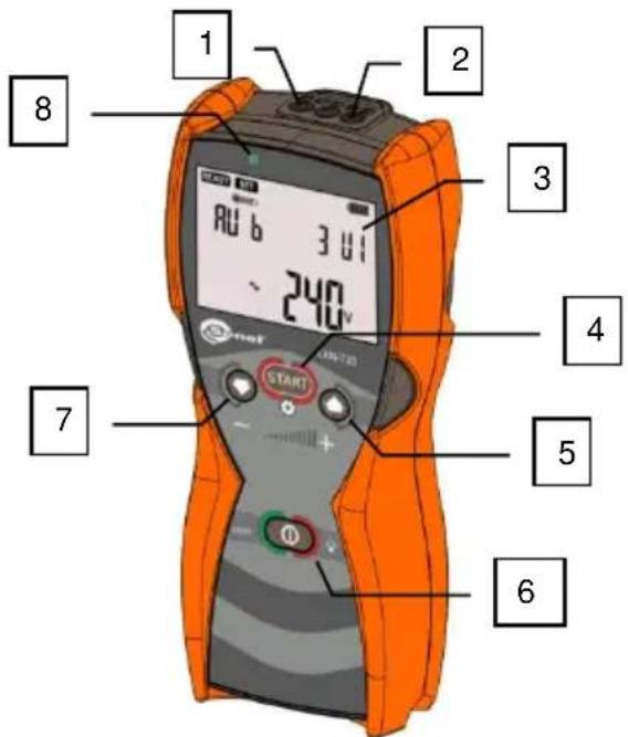
Fig. 1 Front panel.
| No. | Designation | Function Description |
| 1 | N | N banana socket of the transmitter. |
| 2 | L | L banana socket of the transmitter. |
| 3 | LCD | Display of the transmitter status and the connected object. |
| 4 |  | Start/Stop of signal transmission.Accessing the menu settings.Confirmation. |
| 5 |  | Increasing the level of the transmitted signal.Navigating in Menu. |
| 6 |  | Switching the power supply ON/OFF.Force switching the power supply OFF (approx. 10 s).Switching LCD ON and selecting its backlight brightness. |
| 7 |  | Decreasing the level of the transmitted signal.Navigating in Menu. |
| 8 | LED | Two-colour LED indicator:Green: correct signal transmission,Red: incorrect or missing signal transmission. |
2.1.2 LCD Display
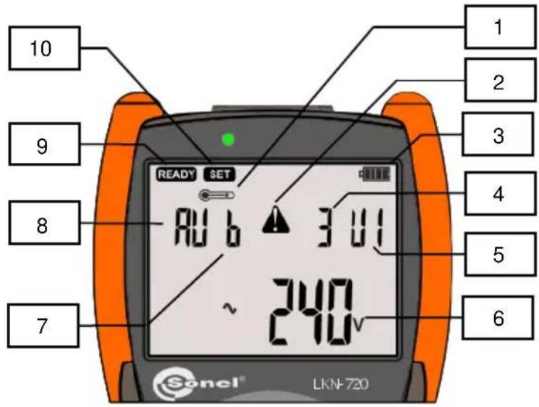
Fig. 2 Transmitter - LCD display.
| No. | Figure | Function Description |
| 1 |  | Temperature exceeded. |
| 2 |  | Warning! High voltage. |
| 3 |  | Battery/accumulator charge status. |
| 4 | Strength of the transmitted signal. | |
| 5 | Mode of the transmitted signal. | |
| 6 | Voltage present on tested object.Menu mnemonics. | |
| 7 | Code of the transmitted signal. | |
| 8 | Automatic mode enabled. | |
| 9 |  | The meter is ready for work |
| 10 |  | Menu of transmitter settings |
2.1.3 Operation
2.1.3.1 Turning the power ON
Press ON/OFF button to turn the device ON. The display will show the test screen and software version number.
2.1.3.2 Turning the power OFF
Press ON/OFF button and hold it until the display shows OFF.
2.1.3.3 Selecting the operating mode or entering the transmitter settings
Press MENU/START START button and hold it until the display shows the name of operation mode or the transmitter settings.
Use UP DOWN buttons to select the operation mode or menu settings of the transmitter.
Confirm the selection of the mode by pressing MENU/START .
a) Transmitter settings SET
After confirming, the following settings of the transmitter are available. Selection is made using UP

DOWN

| Code | Selecting the transmission code. |
| Sync | Synchronization of the transmitter with the receiver. |
| UPGr | Transmitter software update. |
| RoFF | Time after which the transmitter turns off. |
b) Measurement mode Auto
Automatic operation mode of the transmitter. After connecting the wires, the transmitter automatically selects the operation mode depending on the electrical conditions in the traced object.
Use the UP DOWN buttons to set the level of the transmitted signal.
c) Measurement mode
Voltage mode of the transmitter. Traced object is an open circuit. No voltage in the circuit.
Use the UP DOWN buttons to set the level of the transmitted signal.
d) Measurement mode Current mode of the transmitter. Traced object is live. Use the UP DOWN buttons to set the level of the transmitted signal.
e) Measurement mode U I Voltage-current mode of the transmitter. Traced object is a closed circuit. Use the UP DOWN buttons to set the level of the transmitted signal.
f) Measurement mode P_r Power mode of the transmitter. Traced object requires strong signal. The object is a closed circuit.
g) Measurement mode P3 The transmitter operates in identification mode. Use UP DOWN buttons to set the reference phase, basing on which the receiver determines the tested phase.
h) Measurement mode CLP Operating mode of the transmitter with transmission clamps. Use the UP DOWN buttons to set the strength of the transmitted signal.
2.1.3.4 Switching the transmitted signal ON - OFF
Briefly press MENU/START START to start signal transmission. Flashing green LED indicates successful start of the signal transmission. LED flashing red indicates that signal transmission is impossible in the selected mode.
Use the UP DOWN buttons to change the level of the transmitted signal during transmission. Pressing button START again disables the signal transmission.
CAUTION!
When pictogram is displayed, it means that the internal transmitter modules responsible for transmitting the signal heated up above the allowable threshold. Wait until the device cools down and the then the pictogram will disappear. During the transmission blockade, you can use other functions, e.g. you can change the transmission mode, transmission code, the time for auto shutdown, etc.
2.1.3.5 Switching LCD display ON and selecting its backlight brightness.
When button is pressed at any time of transmitter operation, it will activate its backlight. Subsequent presses increase the brightness of the display twice and then turn off the backlight.
The backlight automatically turns off, after 30 seconds when keyboard is not used, to save power.
2.2 LKO-720 receiver
2.2.1 Front panel
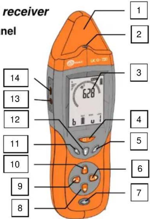
| No. | Designation | Name | Function Description |
| 1 | ANTENNA | Antenna of magnetic and electric fields. | |
| 2 | LED | Flashlight. | |
| 3 | LCD | The display of the receiver. | |
| 4 |  | 3D/2D | Changing the tracing mode. |
| 5 |  | MODE | Selecting the operating mode of the receiver. |
| 6 |  | ABS/REL | Changing the signal display mode - absolute (ABS) / relative (REL) values. |
| 7 |  | ON/OFF | Functions:Switching the receiver ON/OFF.Switching display ON and selecting its backlight brightness. |
| 8 |  | DOWN | Turning down the sound signal level. |
| 9 |  | SOUND | Changing the sound signal. |
| 10 |  | UP | Increasing the sound signal level. |
| 11 |  | SET | Receiver settings. |
| 12 |  | FLASHLIGHT. | Flashlight. Switching ON and selecting the brightness.Hold down the button of maximum brightness mode. |
| 13 | SOCKET 1 | Headphones socket. | |
| 14 | SOCKET 2 | USB slot. | |
| 15 | SOCKET 3 | Socket for accessories. | |
| 16 | COVER | Battery cover. |
2.2.2 Display
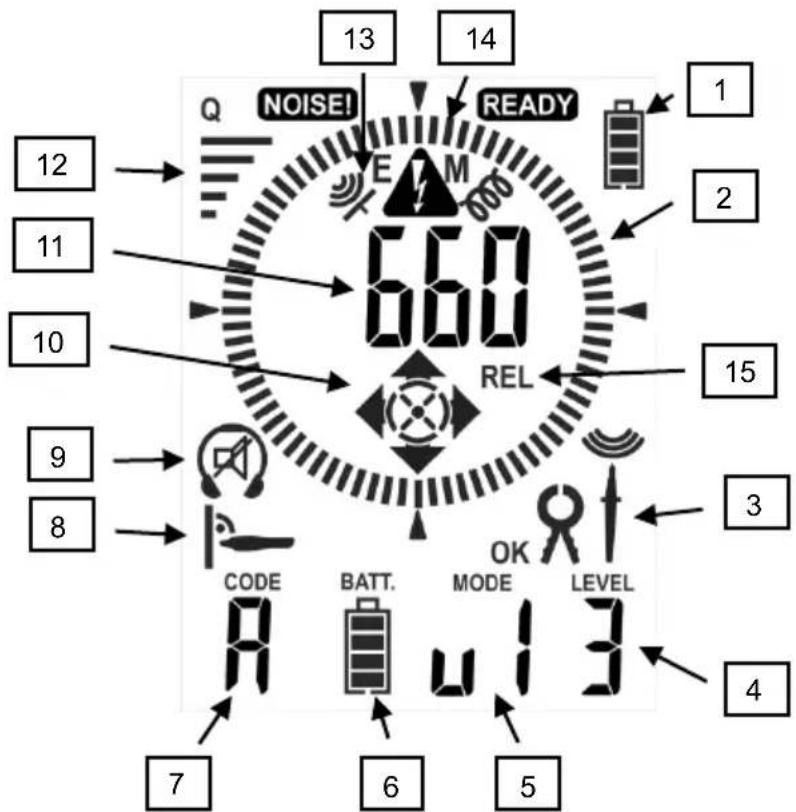
Fig. 4 Rreceiver - LCD display.
| No. | Fig. | Function | No. | Fig. | Function |
| 1 | 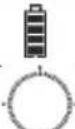 | Battery charge status. | 9 | Headphones connected to the receiver. | |
| 2 | Bar graph - orientation of the traced object. | Sound signals OFF. | |||
| 3 |  | Measuring clamps | 10 | Direction of incoming signal in the traced object: Left - Right. | |
| [8CCO] | Contact probe. | Direction of incoming signal in the traced object: Up - Down. | |||
 | Non-contact probe. | Direction of incoming signal in the traced object: "Arrow head" above, "Tail" - below. | |||
 | The direction of the signal in accordance with marking on the accessories. | 11 | Received signal strength. | ||
| 4 |  | The level of the transmitter signal. | 12 | Received signal quality. | |
| 5 |  | Operation mode of the transmitter. | 13 | Signal detection using the built-in magnetic field antenna | |
| 6 |  | Status of batteries/rechargeable batteries in the transmitter. | Signal detection using the built-in electric field antenna | ||
| 7 |  | Code of the transmitted signal. | 14 | Detecting high voltage in the traced object. | |
| 8 |  | Recommended position in relation to the traced object. | 15 | Relative indication of the received signal. |
2.2.3 Operation
2.2.3.1 Switching the receiver ON
Press ON/OFF button. The test screen will be displayed with software version of the receiver.
2.2.3.2 Switching the receiver OFF
Press ON/OFF button and hold it until the display shows OFF.
2.2.3.3 Selecting the operating mode of the receiver
Select the operating mode of the receiver by pressing sequentially MODE button.
a) Operating mode

Detection of the magnetic field of traced signal. A signal from a synchronized transmitter is required. In this mode, two methods may be used for tracing the object.
The method is selected by using 3D/2D

- Method 2D

Pictogram shows the received signal strength. In this mode, search for the strongest signal level and after locating the object, you can switch to 3D method.
- Method 3D
It is indicated on the display by pictogram of the recommended position in relation to the traced object.

Pictogram indicates the position of the object in relation to the antenna.
Pictograms ◀, ▶, ▲, ▼, ⊙, ⊗ indicate the location of the transmitter.
b) Operating mode

Detection of the magnetic field of traced signal. A signal from a synchronized transmitter is required. In this mode, similarly to the previous one, two methods may be used for tracing the object - 3D/2D.
This mode differs from the previous one: in 3D method the receiver must be held in parallel to the traced conductor - not in perpendicular. This facilitates locating conductors and cables installed in the ground.
c) Operating mode

Detection of the electric field of traced signal. A signal from a synchronized transmitter is required.
d) Operating mode

Indicator of 50-60 Hz electric field from the mains.
e) Operating mode

Identification of the electrical network phase in reference to the phase specified by the transmitter.
f) Operating mode FUSE
The identification of circuit breakers in electric circuits. The transmitter is connected to the circuit, in which the circuit breaker must be located. The receiver locates fuse indicating the maximum signal level and activated the flashlight in the place of identified the fuse.
2.2.3.4 Changing the sound signal.
Change the sound signal by pressing sequentially SOUND button.

2.2.3.5 Adjusting the sound signal strength
Adjust the strength of the sound signal using
UP+ and DOWN

buttons.
2.2.3.6 Changing the displayed value of signal strength in relation to signal reference value
The change is made using ABS/REL button. After pressing the button, the display will prompt you to activate the relative mode. The signal level displayed on the screen will have the value related to the reference value at the moment of activating the mode.
Return to the absolute mode by pressing ABS/REL button until the message is displayed (absolute) Abs
2.2.3.7 Receiver settings.
Receiver settings include controls for increasing the buzzer and headphones signals, setting the time for automatic shutdown after a period of inactivity (auto off).
Set the receiver in settings menu, which is accessed by pressing SET button. By each press you may select between settings.
2.2.3.8 Switching and adjusting backlight brightness.
Switch the LCD backlight by pressing ON/OFF button. Pressing the button twice sequentially change the backlight brightness or disable it.
2.2.3.9 Turning the flashlight ON and OFF

button. Pressing the button twice sequen-
Turn the flashlight ON by pressing FLASHLIGHT button. Pressing sequentially the button you may change the brightness of the flashlight. By holding down the flashlight button you may activate its maximum brightness.
3 Principle of system operation
LKZ-720 set consists of two devices: LKN transmitter and LKO receiver. The transmitter connected to the traced circuit forces respective field around the circumference of the circuit: magnetic field(current mode) or electrical field (voltage mode).
The magnetic field is generated by the flow of appropriately modulated current through the tested (closed) circuit. The electric field is generated by producing respectively modulated voltage in the tested (open) circuit (the flow and shape of this field depends largely on the environment in which it is produced). The receiver placed along the tested circuit detects the modulated field and inform the user about it. Tracing the routing circuit or its damage is possible by observing the level of the detected signal.
3.1 Transmitter LKN-720
Electromagnetic signals sent by the transmitter are appropriately modulated. This enables distinguishing these signals from other signals that may be present in tested circuit or in its close environment. The signal is also characteristic for respective transmission modes to enable the receiver remotely interpret the signal. Transmission modes are switched automatically depending on the connected circuit, which is traced. The transmission mode may be also selected using the following sequence:
| No. | Button | Description |
| 1 |  | Press and hold START button for approx. 1 sec. |
| 2 |  | Use UP and DOWN buttons to select the desired mode. |
| 3 |  | Confirm. |
| 4 |  | Start the transmission. |
| 5 |  | Adjusting the transmission power. |
Starting the transmission will activate LED. The green colour of the signalling LED indicates the correct transmission of tracing signal, while red colour of LED red indicates the incorrect choice of the operating mode for the type of the circuit connected with the transmitter.
3.2 Receiver LKO-720
The receiver head Fig. 3 has two detectors: one for electric and one for magnetic field. The electric field detector is a planar antenna designed to detect changes in the electric field in accordance with the signal generated by the transmitter. The magnetic field detector is an antenna designed in 3 planes, which allows detecting the direction of signal transmission. Strength of the electric or magnetic field is depicted by "tilting" the indicator bar graph (Fig. 4ref. 2) and the display shows the numerical value of the received signal level.
3.3 Synchronization of the transmitter with the receiver.
The frequency of the clock signal of transmitter (transmitters), which is used for generating the locating signal must be the same as the frequency of the clock signal of the receiver.
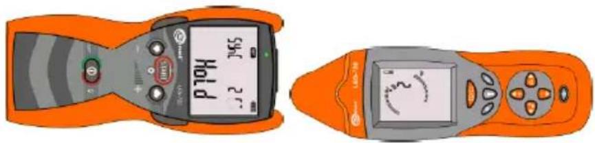
natural_image
Illustration of two orange handheld devices with digital displays and control knobs (no text or symbols)Fig. 5 Positioning the transmitter and receiver during synchronization
Synchronization procedure of the transmitter with the receiver.
| Transmitter setting:. | |||
| No. | Button | Operation | Screen |
| 0 | Arrange the units as illustrated. | ||
| 1 |  | Turn the transmitter ON. | |
| 2 |  | Press and hold START button. | |
| 3 |  | Use UP and DOWN buttons to select the menu settings of the transmitter. | SET |
| 4 |  | Confirm your selection. | |
| 5 |  | Use UP and DOWN buttons to select the synchronization mode. | SYNC |
| 6 |  | Confirm your selection. | |
| Receiver settings: | |||
| 7 |  | Hold 2D/3D button and switch on the receiver by pressing ON/OFF. | CLSYNC |
| 8 |  | Confirm your selection of synchronization by using FLASHLIGHT button. | |
The synchronization should be carried out in case of incorrect operation of the system, which is indicated by a lack of clear information about the status of the transmitter obtained from strong detected signal. Information about the operational status of the transmitter may be obtained in magnetic mode (3D) and electric mode (uAnt).
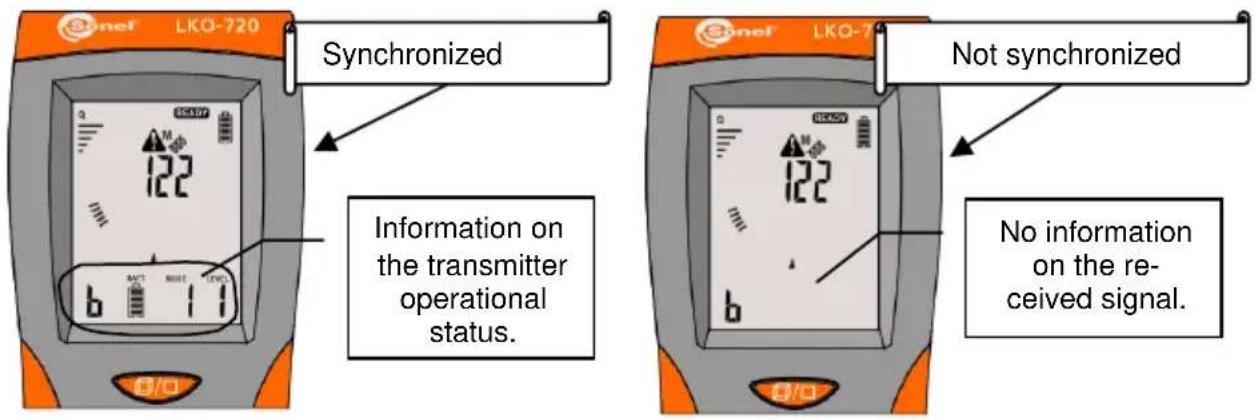
Fig. 6 Synchronization and its absence.
If the received signal is strong, but the signal indications are unstable, the synchronization must be also carried out.
Remember to use the receiver at a distance of more than 1m from the transmitter when locating the objects.
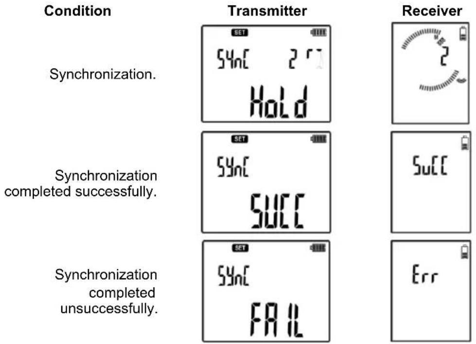
During the synchronization, the screens of devices show messages about the synchronization progress.
other
| Condition | Transmitter | Receiver | | --- | --- | --- | | Synchronization. | Sync | 2 | | Synchronization completed successfully. | Sync | 10 | | Synchronization completed unsuccessfully. | Succ | 10 | | Synchronization completed unsuccessfully. | Fail | Err |After starting the synchronization, LKN and LKO screens display the progress of the synchronization in three steps numbered from 0 to 2. "HOLD" message displayed by the transmitter means that the transmitter should not be moved at this time in relation to the receiver. After the process, the receiver and transmitter must be turned off. The whole process takes about 3 minutes.
In the case of unsuccessful synchronization, the process must be repeated after changing the position of the transmitter in relation to the receiver. Err message indicates errors in the radio communication between devices due to external interference. Fail message indicates insufficient signal strength for the synchronization, e.g. when the receiver is not placed near the transmitter.
3.4 Modes of system operation
The system may work in one of the available modes: current, voltage or voltage-current, phase identification, power, system security location, clamp and neon lamp.
In "AUTO" mode, the transmitter connected to the circuit, selects the most favourable mode, basing on the conditions in the tested line.
In the receiver, use MODE button to change the operation mode, i.e. select the voltage path (connected to electric field antenna) or current path (connected to magnetic field antenna) or to switch the receiver into the other modes. In most cases, the path voltage is switched at the voltage mode of the transmitter, while the current path at the current or voltage-current mode of the transmitter. However, in certain circumstances, another field may be stronger than it is indicated by the operation mode of the transmitter, therefore you have the possibility to choose.
3.4.1 Current mode I
Operation in current mode "I" may be performed on undamaged conductors being under voltage of at least 9V.

Fig. 7 Diagram of the current mode.
One output of the transmitter is connected to the phase conductor for AC network or positive conductor for DC network of the tested circuit, while the other to the neutral conductor. Voltage existing in the circuit it is used by the transmitter to generate a current signal (max. 40mA) as a high-frequency pulses distributed in time in the manner typical of the current mode. The magnetic component of the field generated in this way is detected by the receiver.
Operation in voltage mode "U" is used for cables without voltage, when it is impossible to create a closed circuit (e.g. break in the conductor).
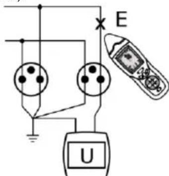
Fig. 8 Diagram of the voltage mode.
One output of the transmitter is connected to the tested conductor, while the other is connected to the ground, along with other cores of traced cable. The transmitter generates a voltage signal in the form of high-frequency pulses distributed in time in the manner typical of the voltage mode. The generated electric field is detected by the receiver.
3.4.3 Voltage-current mode UI
Operation in voltage-current mode "UI" is used for cables without voltage, when a closed circuit is created (e.g. unbroken line without voltage, shorted line).
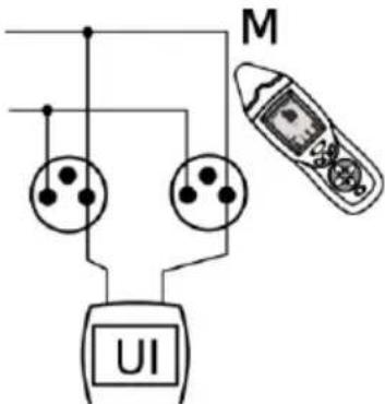
Fig. 9 Diagram of the voltage-current mode.
One output of the transmitter is connected to the phase conductor or neutral conductor of the tested circuit, while the other respectively to the phase conductor or neutral conductor. The transmitter, using own supply voltage, generates a current signal (max. 40mA) in the form of pulses distributed in time in the manner typical of the voltage-current mode. The magnetic component of the field generated in this way is detected by the receiver.
3.4.4 Mode of detecting P3 phase
LKZ-720 may operate in P3 mode, which is called "phase" mode. It involves the transmitter set in mode P3, which is connected to a live circuit - between the phase conductor L and a neutral conductor N or PE grounding.
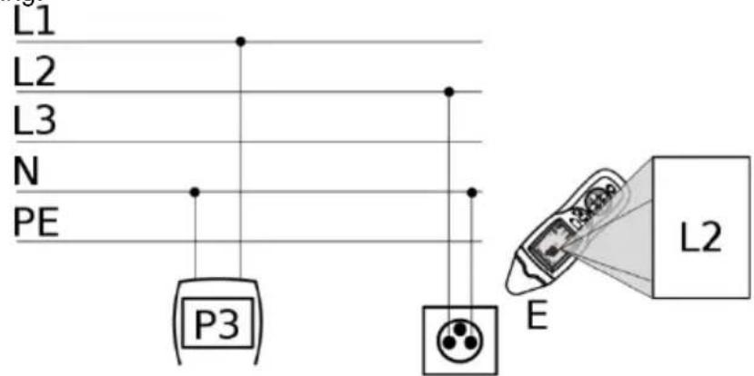
Fig. 10 Diagram of detecting P3 phase.
The user specifies the number of the reference phase, connected to the transmitter. Set P3 mode in the receiver. The receiver identifies the phase of the tested conductor, using information provided by transmitter via radio and basing on the voltage crossing zero.
3.4.5 Power mode - Pr
LKZ-720 may operate in "Pr" mode, which is called "Power" mode. It involves the transmitter set in "Pr" mode and connected to the closed circuit without voltage.
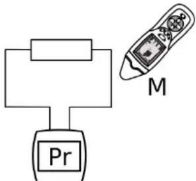
Fig. 11 Diagram of the power mode.
In the circuit, the transmitter forces the current flow limited by circuit impedance. The received signal is proportional to the current flow, which translates into a significant increase in the object detection range.
This mode is particularly suitable for tracing the cable routes.
Note
Due to the high power consumption in Power mode, take into account rapid discharge of batteries/rechargeable batteries that supply the transmitter.
Note
When the impedance is too low, transmission may not possible in this mode. Then, use the voltage-current mode (UI.
3.4.6 The mode of detecting safety devices - FUSE
This set allows the location of system safety devices. It involves the transmitter, which is connected to a live circuit - between the phase conductor L and a neutral conductor N - and which generates current waveforms in the tested circuit.
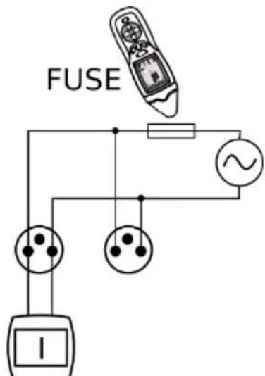
Fig. 12 Diagram of the mode of detecting safety devices.
Move the receiver or a non-contact probe connected to the receiver along the safety devices. The location of detected circuit will be indicated on the receiver.
3.4.7 Clamp mode - CL
Clamp mode "CL" is used for introducing signal into circuit, where it is impossible to disconnect the line.
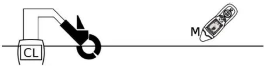
Fig. 13 Diagram of the clamp mode.
Transmission clamps are used in closed circuits, which may carry AC up to 15A.
Remember that the current value in the tested system of 50/60Hz must not cause the saturation of clamps (in such case characteristic buzz is heard in the clamps).
If possible, fix the clamps on a multi-core cable, not on the individual cores (conductors).
3.4.8 Mode for detecting 50Hz/60Hz electric field - NEON
Using only the receiver you may use non-contact "Neon" mode to locate wires under voltage with a frequency of 50Hz/60Hz. Remember that the electric field is deformed by various conductors e.g. reinforcement bars, steel or copper pipes etc. If a conductor with 230V AC of 50Hz runs near a conductive tube, a voltage with frequency of 50Hz may be induced in the pipe causing false results.
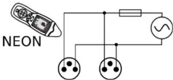
Fig. 14 Diagram of detecting 50Hz/60Hz electric field.
3.5 Operation in IT networks
Despite the differences between the power supply systems, the device is fully functional in IT networks. Non-voltage modes always work applying the same principle, regardless of network type. In turn, the operation of voltage modes is not influenced by the additional impedance present in the earthing location of neutral / central point.
The only mode that requires the user to remember about differences between networks is P3 function of identification of phases. The determination of the reference phase requires a transmitter connected between the tested phase and the neutral conductor N or protective earthing conductor PE of the network.
Non-contact phase detection with the receiver may be adversely affected by the close proximity of:
- current circuits of individual phases in electrical sockets.
- current circuits in two-pole overcurrent protection devices,
- other interfering factors.
Therefore, in such cases it is recommended to use a contact probe.
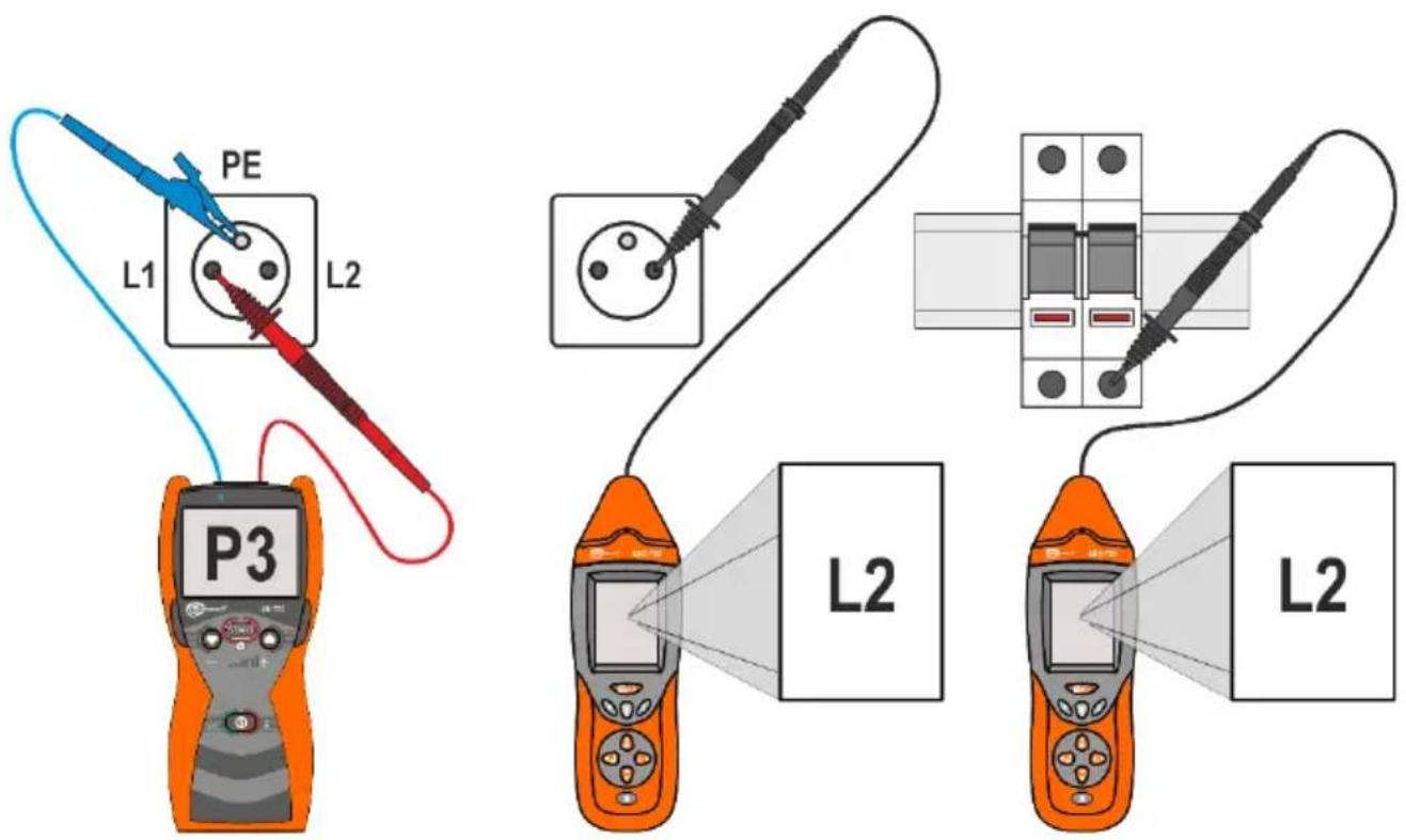
Fig. 15 Identification of phases in IT networks.
4 Operation
Before the measurements, make sure that the condition of the battery or rechargeable batteries in the transmitter and the receiver is sufficient for performing tasks related to the operation of the device.
When the screen of the receiver starts to alternately display words "Lo" and "bAtt" which is followed by switching off the receiver - it means that the battery is completely discharged.
When the transmitter displays "bAtt" it means that batteries/rechargeable batteries are discharged - the meter may be only turned off.
4.1 Replacing the power supply
4.1.1 Receiver
The receiver should use batteries with the following parameters:
- Size: 6LF22
- Rated voltage: 9V
Battery replacement procedure:
- turn the receiver OFF,
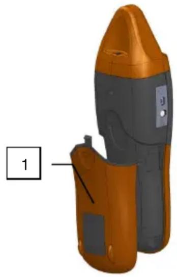
- remove the battery cover 1 - Fig. 16,
- replace the battery,
- insert the battery compartment cover taking care that the side guides and central cover latch are in the right place.
natural_image
3D model of a handheld device with orange and gray casing, labeled with number 1 (no text or symbols on the device itself)Fig. 16 Replacing the power supply.
CAUTION! Have the meter serviced in case of battery leakage inside the compartment.
4.1.2 Transmitter
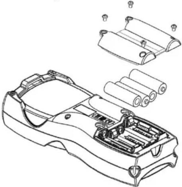
In the transmitter, the power may be supplied by 4 batteries (size AA) or by NiMH rechargeable batteries with voltage not exceeding 1.5V per cell. Replacing batteries/rechargeable batteries must be performed in the device not connected to any object.
Due to the high energy consumption in some transmission modes, it is recommended to use rechargeable batteries.
After each replacement of batteries/rechargeable batteries, enter the information about the installed energy source: batteries - rechargeable batteries - .
natural_image
Technical line drawing of a car body panel assembly with exploded view (no text or symbols)Fig. 17 Transmitter - battery replacement.
Battery replacement procedure:
| No. | Operation | Screen / Comments |
| 1 | Disconnect the unit from the object! | |
| 2 | Turn off the transmitter and use a screwdriver to unscrew the battery cover (four M3 screws M3 with cross head). | Fig. 17 |
| 3 | Replace the batteries or rechargeable batteries. | |
| 4 | Close the lid. | |
| 5 |  Turn the transmitter ON. Turn the transmitter ON. | |
| 6 |  select type of applied energy source select type of applied energy source  or or  |   |
| 7 |  Confirm. Confirm. |
CAUTION! Have the meter serviced in case of battery leakage inside the compartment.
Rechargeable batteries must be recharged in an external charger, which is not provided with the set.
4.2 Energy-saving function: AUTO-OFF
4.2.1 Transmitter
Due to a significantly high energy consumption from the installed sources, a system of automatic switch-off was installed in the device.
The transmitter will turn off after a time defining the condition in which the device was active but not used - no button was pressed. The maximum auto-off time is 300 minutes in 10 minute-steps.
The procedure for setting auto-off time in the transmitter.
| No. | Operation | Screen / Comments |
| 1 |  Turn the transmitter ON. Turn the transmitter ON. | 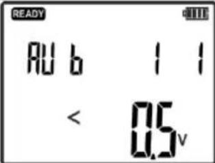 |
| 2 |  Press and hold. Press and hold. | 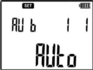 |
| 3 |  select settings. select settings. | 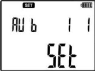 |
| 4 |  Approve Approve | |
| 5 |  | 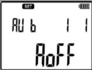 |
| 6 |  Confirm. Confirm. | |
| 7 |  set timeSTARTand confirm. set timeSTARTand confirm. | 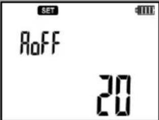 |
4.2.2 Receiver
In the receiver, the AUTO-OFF system will switch off the device after the time specified by parameter. The time is counted from the last pressing of any button. Time is specified in minutes.
The procedure for setting Auto-OFF time.
| No. | Operation | Screen / Comments | |
| Receiver: | |||
| 1 |  Turn the receiver ON. Turn the receiver ON. | ||
| 2 |  Press and hold SET button. Press and hold SET button. | 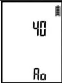 | |
| 3 |  select the auto-off time. select the auto-off time. | ||
| 4 |  Single pressor Single pressor | Saving AutoOFF values and moving tothe next parameteror | |
| 5 |  press and hold press and hold | save the values and exit the menu. | |
4.3 Setting audio path gain.
The receiver is equipped with a sound information system in the detected object. Strength and frequency of sound signals are used by the receiver to inform the user about the level and change in the signal received during the search/tracing of the object.
During receiver operation in modes IAnt, Cabl, uAnt, Neon user may press SOUND to select the appropriate signal type, which helps in locating and identifying an object.


Use UP and DOWN buttons to change the intensity of the generated sound in audio path of the buzzer or headphones. For each audio path available in the menu, an additional separate gain control is available for the buzzer and headphones.
The procedure for setting an additional gain control.
| No. | Operation | Screen / Comments | |
| Receiver: | |||
| 1 |  Turn the receiver ON. Turn the receiver ON. | ||
| 2 |  Press and hold SET button. Press and hold SET button. | 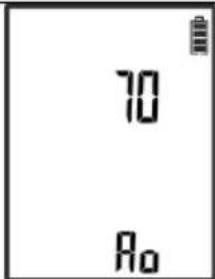 | |
| 3 |  Press repeatedly to select (headphones) for gain settings of headphones or buzzer) for gain settings of the buzzer. Press repeatedly to select (headphones) for gain settings of headphones or buzzer) for gain settings of the buzzer. | 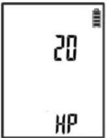 | |
| 4 |  orset the gain of the selected path orset the gain of the selected path | Changing gain value from 0 to 20.Setting "0"- no sound signal.Setting "20"- maximum gain. | |
| 5 |  Single pressor Single pressor | Saving gain values and moving to the next parameteror | |
| 6 |  press and hold press and hold | save the values and exit the menu. | |
4.4 Setting the transmitter code
Each transmitter has the ability to set a code that is recognized by the receiver. Available codes: A, B, C, D. The setting of the code is recommended during the identification and tracing processes that use many transmitters.
The procedure for setting code of the transmitter.
| No. | Operation | Screen / Comments | |
| 1 |  Turn the transmitter ON. Turn the transmitter ON. | 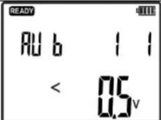 | |
| 2 |  Press and hold. Press and hold. | 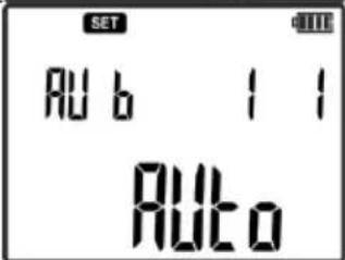 | |
| 3 | 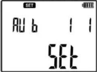 | ||
| 4 |  Approve Approve | ||
| 5 |  orselect menu of code selectionCode orselect menu of code selectionCode | 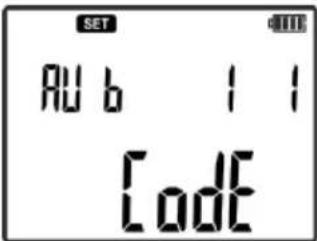 | |
| 6 |  Confirm. Confirm. | ||
| 7 |  orset the required code. orset the required code. | 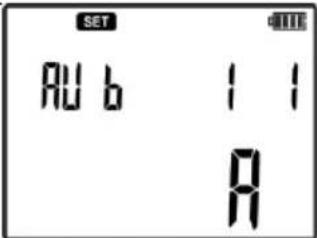 | |
| 8 |  Confirm. Confirm. | ||
5 Measurements
5.1 Detecting cables in ceilings, walls and floors
5.1.1 Live cables
For locating live wires and those installed in ceilings, walls or floors, the locating signal is forced by the transmitter in the form of current pulses. The receiver locates the current flow in the conductor/wire by measuring changes in the magnetic field and decoding the transmitted signal. Select Current mode I or AUTO mode in the transmitter, IAnt mode in the receiver, in accordance with the procedure of locating objects under voltage.
Due to the physics of magnetic field distribution, the best results are achieved for the circuits, which have the signal in the form of current flow to and from the transmitter connected as shown in a Fig. 18 b), c).
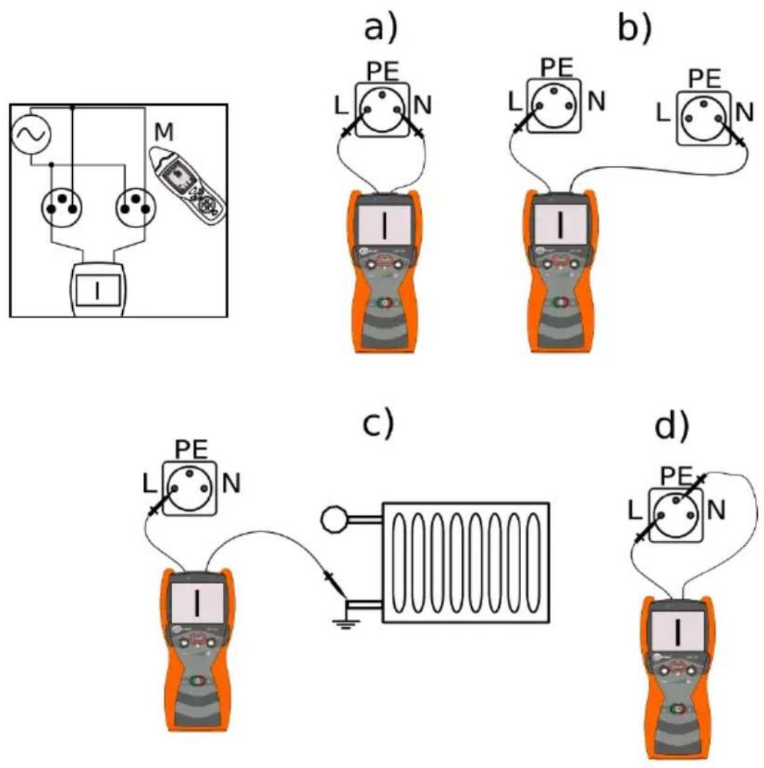
Fig. 18 Examples of connecting the transmitter to the electrical system.
If you connect the transmitter according to Fig. 18 a) for conductors with current flow to and from the transmitter situated close together, the magnetic field generated in the two conductors as a result
of forcing the current by the transmitter penetrate each other. Fig. 19 shows vectors of magnetic field induction for two cases of connecting the transmitter to the circuit. In case of conductors lying close to each other, the resultant vector of the magnetic field is highest in their vicinity, between conductors. When the distance from the conductors increase, the vectors of the magnetic field, seen by the receiver, cancel each other out, affecting the locating abilities of conductors. For a single conductor, a lack of mutual cancelling out of the magnetic field causes the strength of the received signal much greater for larger distances of the receiver from the analysed object.
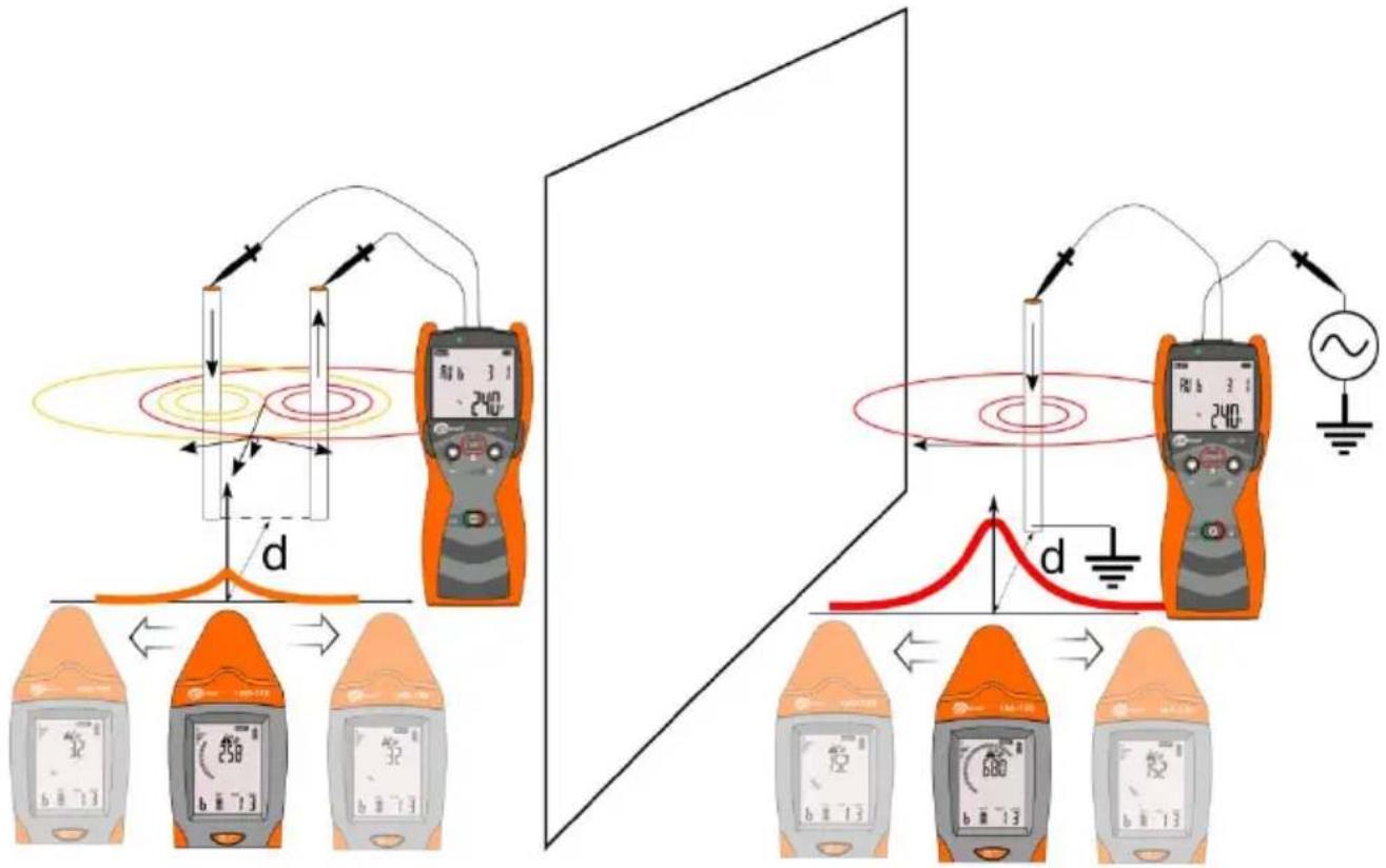
Fig. 19 Vectors of the magnetic field in two parallel conductors.
The procedure for locating conductors or cable lines in live systems:
| No. | Operation | Screen / Comments | |
| Transmitter: | |||
| 1 |  Turn the transmitter ON. Turn the transmitter ON. | 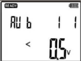 | |
| 2 |  Press and hold until the screen with selection menu of transmission modes is displayed.SET Press and hold until the screen with selection menu of transmission modes is displayed.SET | 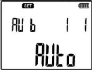 | |
| 3 |  select I or Auto mode. select I or Auto mode. | 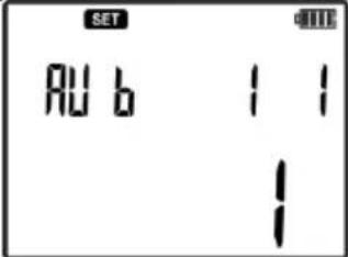 | ||
| 4 |  Confirm. Confirm. | |||
| 5 |  -set the required signal level. -set the required signal level. | |||
| 6 | Connect one of the banana sockets of transmitter L or N to grounding. | Fig. 18 b) c) | ||
| 7 | Connect the second socket to the phase conductor in the socket outlet, switch, etc. | Fig. 18 b) c) | ||
| 9 |  Start the transmission. Start the transmission. | Flashing LED:green - correctly selected mode.red - incorrectly selected mode. | ||
| Receiver: | ||||
| 10 |  Turn the receiver ON. Turn the receiver ON. | |||
| 11 |  Press the button and set current mode -IAnt. Press the button and set current mode -IAnt. | 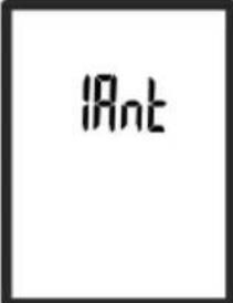 | ||
| 12 | Direct the head of the receiver towards the highest value of the signal level to locate the conductor. | 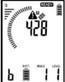 | ||
| 13 |  Press the button to switch the receiver into 3D mode.Locate the cable as indicated on the receiver screen.Description of the individual screens is presented in the section below. Press the button to switch the receiver into 3D mode.Locate the cable as indicated on the receiver screen.Description of the individual screens is presented in the section below. | 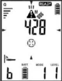 | ||
| 14 | Move the head of the receiver along the traced line, following the maximum signal strength. | Fig. 20, Fig. 21 | ||
Description of individual screens for position in relation to a wire / cable with signal.
flowchart
graph TD
    A["Conduct"] --> B["IAnt"]
    B --> C["Cable"]
    C --> D["A"]
    C --> E["B"]
    C --> F["C"]
    style A fill:#f9f,stroke:#333
    style D fill:#ccf,stroke:#333
    style E fill:#ccf,stroke:#333
    style F fill:#ccf,stroke:#333
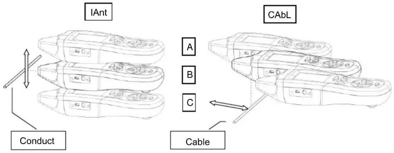
Fig. 20 Locating conductor/cable located in perpendicular to the symmetry axis of the receiver.
For the receiver positioned in relation to the conductor or cable, as shown in Fig. 20, the screen will show individual cases:
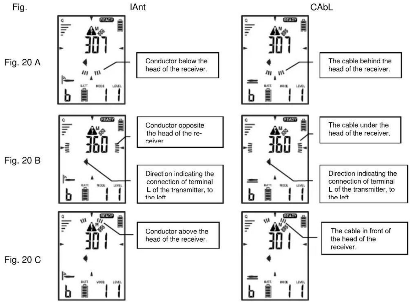
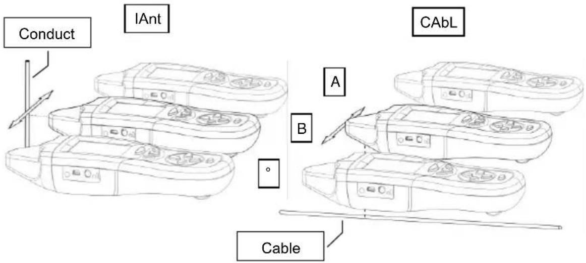
Fig. 21 Locating conductor/cable located in parallel to the symmetry axis of the receiver.
Fig. 21 presents an example of receiver perpendicular to the traced conductor. Screens for individual cases are as follows:
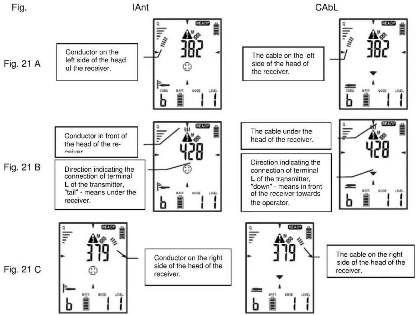
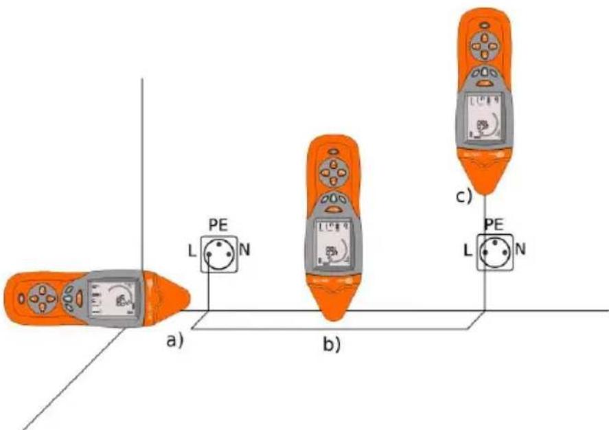
Fig. 22 Using the receiver in IAnt current mode
Na Fig. 22 presents an example of receiver positioned in relation to the traced conductor. In all three cases, you may use the mode indicating the signal level. Since the device is equipped with 3D antenna, the resultant magnetic field vector does not depend on the position of the receiver's head, when it is all the time at the same distance from the object(s).
However, when you want to use 3D mode, which displays information on the receiver's screen, indicating the direction of the analysed object and location of the transmitter - the positioning of the receiver's head is crucial. In such case, avoid detecting at the bends - as shown in Fig. 22 a). Indicated directions of the resultant magnetic field vector may be misleading. In this case, follow only the level of the received signal.
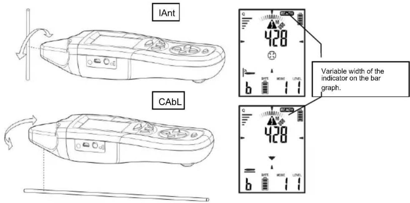
Fig. 23 Width of the indicator on the bar graph.
The width of the indicator on the bar graph represents the deviation of the receiver from the plane parallel or perpendicular to the analysed wire / cable.
5.1.2 Conductors without voltage
In case of open circuits, without the possibility of forcing the current, you may locate a conductor by generating a signal by the transmitter in "U" mode. The resulting electric field is decoded by the receiver enabling the location of conductors.
| CAUTION!Metal, ungrounded elements such as metal frames of partition walls, window frames or doors located in the alternating electric field cause inaccurate readings of the detected electric field. |
If possible, the metal elements close of the tested conductor must be grounded.
| No. | Operation | Screen | |
| Transmitter: | |||
| 1 |  Turn the transmitter ON. Turn the transmitter ON. | [WAT8T] | |
| 2 |  Press and hold until the screen with selection of transmission mode is displayed. Press and hold until the screen with selection of transmission mode is displayed. | 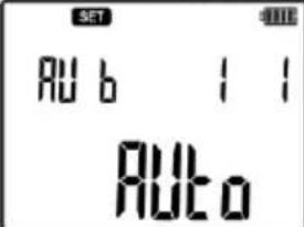 | |
| 3 |  select U or Auto mode. select U or Auto mode. | 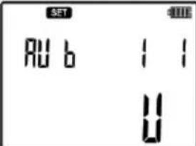 | |
| 4 |  Confirm. Confirm. | 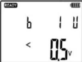 | |
| 5 |  set the required signal level. set the required signal level. | ||
| 6 | Connect one of the banana sockets of transmitter to grounding. | Example Fig. 24Note. When working on the existing heating system or domestic water, make sure that the system is grounded and conductive. | |
| 7 | Connect the second socket to the traced conductor in the socket outlet, switch, etc. | Example Fig. 24 | |
| 8 |  Start the transmission. Start the transmission. | Flashing LED:green - correctly selected mode.red - incorrectly selected mode. | |
| Receiver: | |||
| 9 |  Turn the receiver ON. Turn the receiver ON. | ||
| 10 |  Pressing the key, set voltage mode uAnt. Pressing the key, set voltage mode uAnt. | 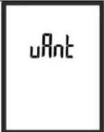 | |
| 11 | Move the head of the receiver along the traced line, following the maximum signal strength. | 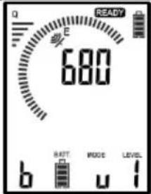 | |
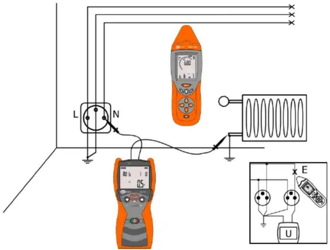
Fig. 24 Locating conductors disconnected from the network in the wall.
5.1.3 Voltage-current mode UI
The voltage-current mode is used in a closed circuit without voltage or with the same potential. Fig. 25 shows an example of the connection. The transmitter connected to the same conductors in two different sockets forms a closed circuit.
| No. | Operation | Screen | |
| Transmitter: | |||
| 1 |  Turn the transmitter ON. Turn the transmitter ON. | 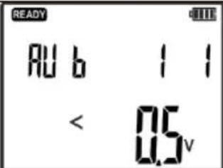 | |
| 2 |  Press and hold until the screen with selection of transmission mode is displayed. Press and hold until the screen with selection of transmission mode is displayed. | 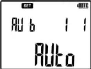 | |
| 3 |  or select UI or Auto mode. or select UI or Auto mode. | 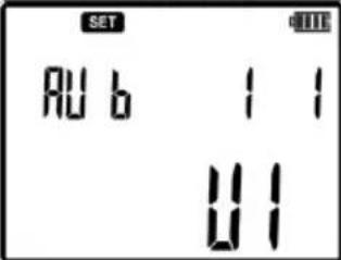 | |
| 4 |  Confirm. Confirm. | 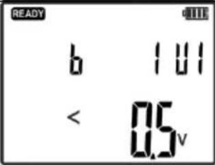 | |
| 5 |  or set the required signal level. or set the required signal level. | ||
| 6 | Connect "L" socket of the transmitter to the phase or neutral conductor in the socket outlet, switch, etc. | Fig. 25 | |
| 7 | Connect the second N socket of the transmitter with a wire of the same potential in a different socket of the tested circuit. | Fig. 25 | |
| 8 |  Start the transmission. Start the transmission. | Flashing LED:green - correctly selected mode.red - incorrectly selected mode. | |
| Receiver: | |||
| 9 |  Turn the receiver ON. Turn the receiver ON. | ||
| 10 |  Press the button and set current mode - IAnt. Press the button and set current mode - IAnt. | 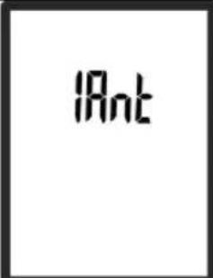 | |
| 11 | Direct the head of the receiver towards the highest value of the signal level to locate the conductor. | 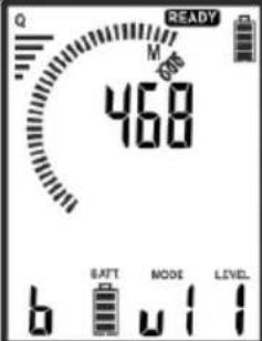 | |
| 12 |  Press the button to switch the receiver into 3D mode.Locate the cable as indicated on the receiver screen.Description of individual screens is presented in sec. 5.1.1. Press the button to switch the receiver into 3D mode.Locate the cable as indicated on the receiver screen.Description of individual screens is presented in sec. 5.1.1. | 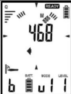 | |
| 13 | Move the head of the receiver along the traced line, following the maximum signal strength. | Fig. 25 (and Fig. 20, Fig. 21) | |
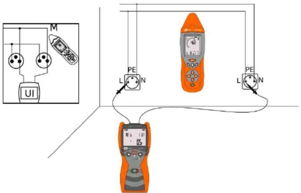
Fig. 25 Locating electrical system using a close loop.
5.2 Locating breaks in cables
Locating breaks in cables is performed in the voltage mode. The procedure of activating the mode is described in sec. 5.1.2. Metal elements located close to the generated electric field, due to the capacitive coupling, cause erroneous readings. For multicore cables, other conductors should be grounded. Therefore, also the other end of the broken cable core should be grounded as in Fig. 26.
Direct the receiver to the strongest signal and move it along the object. The place where the value of the signal drops, may be a potential location of the break.
In the case of locating breaks in shielded cables, finding the break may be difficult. The cable shield is a barrier for localization signal from the transmitter.
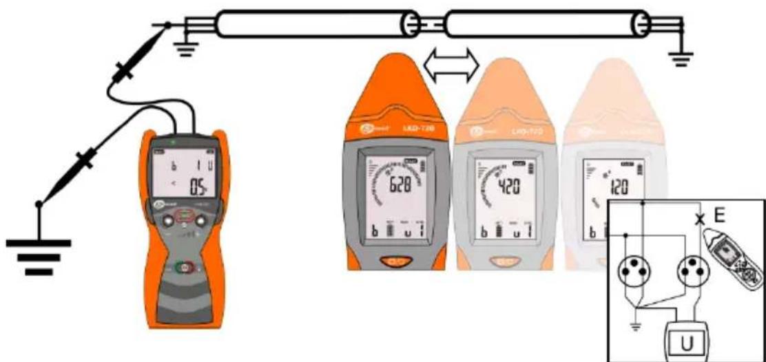
Fig. 26 Locating breaks.
5.3 Identification of cables
Identification of cables is performed in the voltage-current mode (UI). The procedure of activating the mode is described in sec. 5.1.2.
Attach LKN-720 to the cable to be identified: connect 'L' wire to the current conductor and 'N' to the cable shielding. On the other side of the cable, short its current (live) wire with the cable shielding. The shields of all cables subject to identification must be grounded on both sides.
LKN-720 forces the current flow in the tested cable. LKO-720 receiver displays the strength of the signal correlated with the current. The identification involves determining in which of the tested cables, the signal is the strongest.
LKO-720 receiver may be used as a stand-alone device (Fig. 27) or in combination with receiving clamp (Fig. 28).
In the analysed cable:
• the strongest signal is detected,
- for mode without clamp: the receiver will indicate the direction of the signal coming from the transmitter (arrow pointing in the direction of transmitter).
- for mode with clamp: the receiver will indicate "OK" status (note: the arrow on the clamps must be directed toward the transmitter).
In other cables:
• detected signals will be weaker than in the identified cable.
- for mode without clamp: the receiver will indicate the direction of the signal coming to the transmitter - the arrow pointing in the direction of shorted and grounded shielding and current conductor.
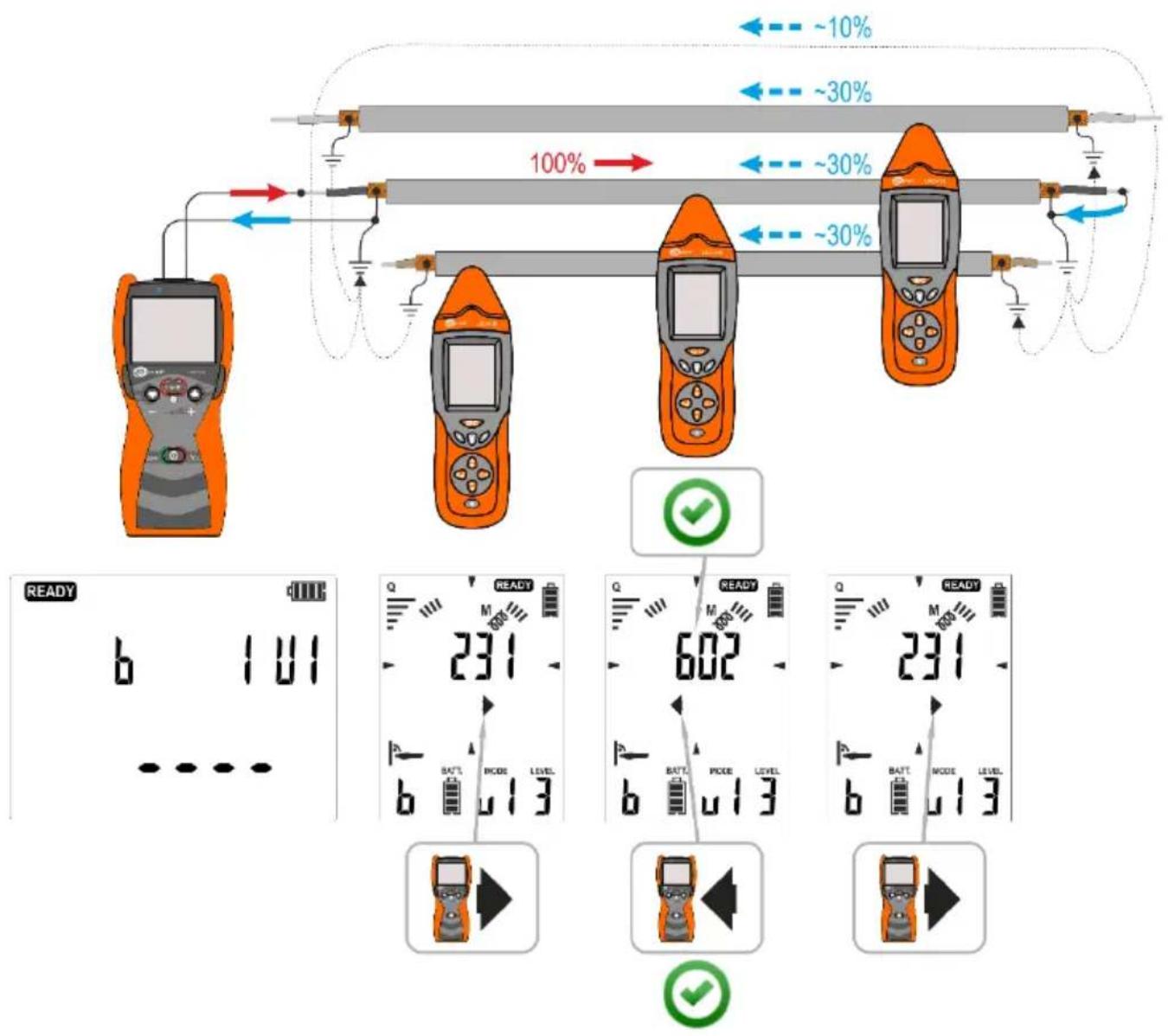
Fig. 27 Identification of a cable using LKO-720.
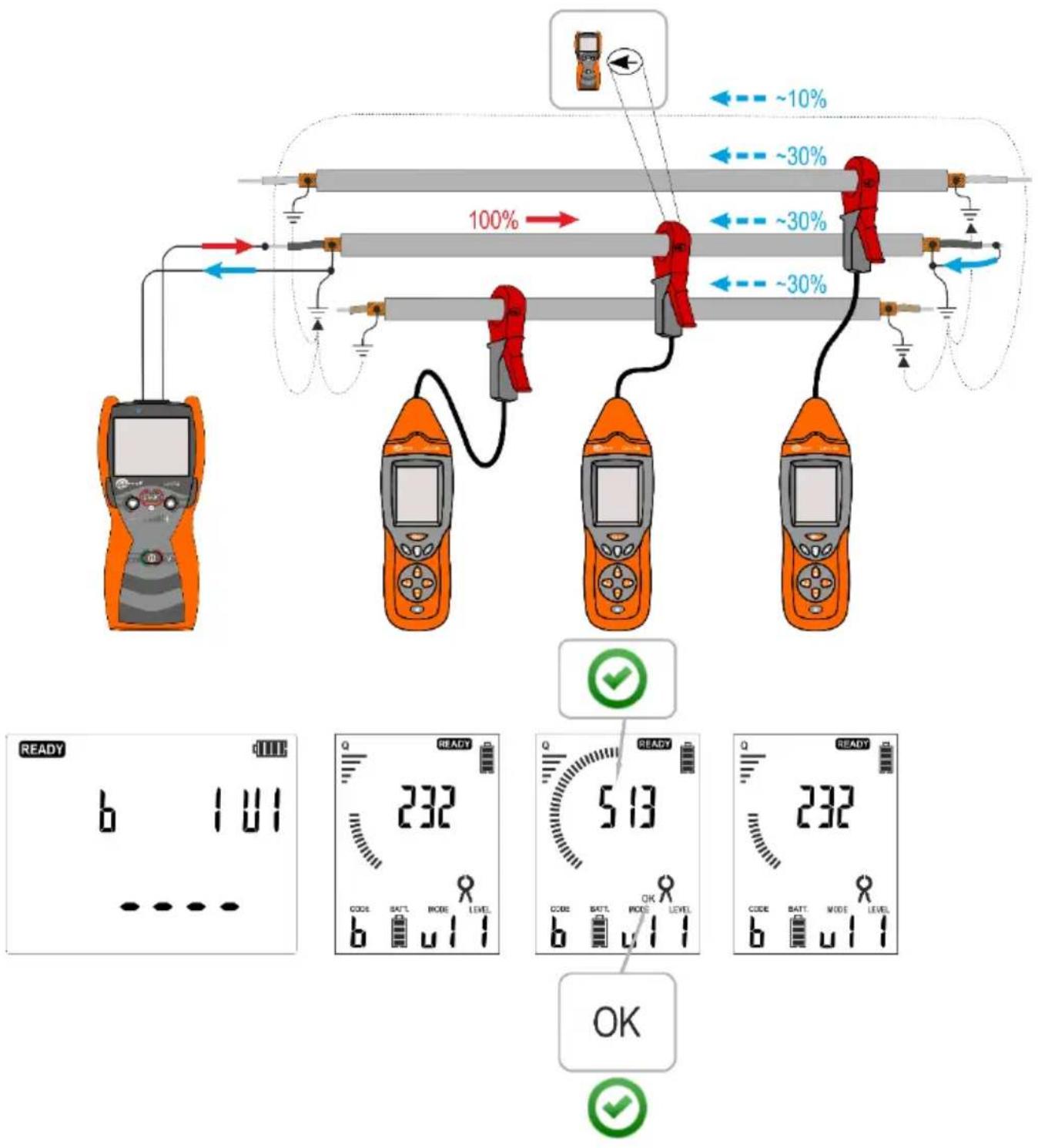
Fig. 28 Identification of a cable using LKO-720 and receiver clamp.
5.4 Locating short-circuits in multicore cables
LKZ system may be used to located short circuits between individual cores of multi-core cables. Fig. 29. Connect the transmitter to the shorted conductors in "UI" mode, forcing current signal in the tested cores. Move the receiver in "3D" mode along the tested wire - location of wire fault will be the last point with the high value of the received signal.
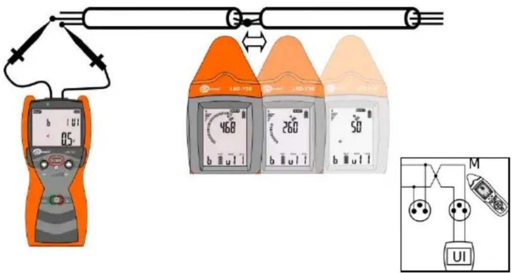
Fig. 29 Locating shorted cores in a conductor.
The procedure for setting the system for locating shorted cores in a conductor.
| No. | Operation | Screen / Comments | |
| Transmitter: | |||
| 1 |  Turn the transmitter ON. Turn the transmitter ON. | 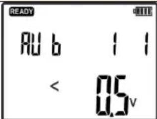 | |
| 2 |  Press and hold until the screen withsettings is displayed. Press and hold until the screen withsettings is displayed. | 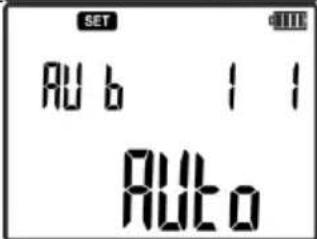 | |
| 3 |  select UI mode. select UI mode. | 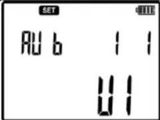 | |
| 4 |  Confirm. Confirm. | 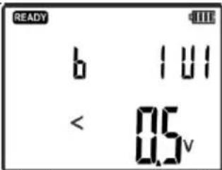 | ||
| 5 |  set the required signal level. set the required signal level. | In the circuit, the current signal is forced with a value equal to the level of:1 = 10mA2 = 20mA3 = 40mA | ||
| 6 | Connect one of the banana sockets of transmitter 1 or 2 to one of the shorted cores. | Fig. 29 | ||
| 7 | Connect the second banana socket of the transmitter to the second shorted core. | Fig. 29 | ||
| 8 |  Start the transmission. Start the transmission. | Flashing LED:green - correctly selected mode.red - incorrectly selected mode. | ||
| Receiver: | ||||
| 9 |  Turn the receiver ON. Turn the receiver ON. | |||
| 10 |  Press the button and set current mode - IAnt. Press the button and set current mode - IAnt. | 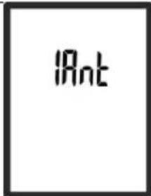 | ||
| 11 | Move the head of the receiver along the traced line, following the maximum signal strength. | Fig. 29 | ||
5.5 Identifying fuses in a switchboard
LKZ-720 system may be used for identifying safety devices in a circuit. In the analysed circuit a current signal is forced, for which a protection is searched in the switchboard. The transmitter must be connected to the circuit in a manner enabling the current flow in the circuit. Connection example Fig. 30.
Rememberer that cables and busbars in switchboards / distribution boxes may falsify the indication of the receiver. To make sure whether the detected fuse/circuit breaker is in the tested circuit, remove the cover of the switchboard and approach the receiver directly to wires and try to locate the circuit.
You may also continue the search using a wireless NCP probe (sec 6.4). Hold it in perpendicular to the switchboard, remembering the arrows on the probe should indicate the top and bottom the overcurrent circuit breaker.
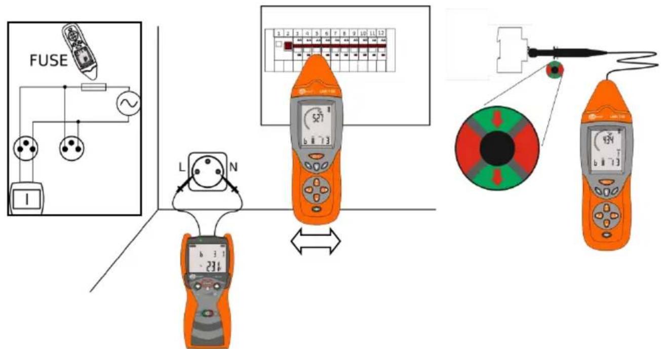
Fig. 30 Identifying safety devices in a switchboard.
The procedure for setting the system to identify safety devices in the switchboard.
| No. | Operation | Screen | ||
| Transmitter: | ||||
| 1 |  Turn the transmitter ON. Turn the transmitter ON. | 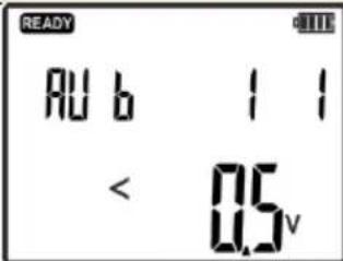 | ||
| 2 |  Press and hold until the screen withsettings is displayed. Press and hold until the screen withsettings is displayed. | 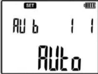 | ||
| 3 |  or select I or Auto mode. or select I or Auto mode. | 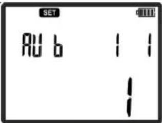 | ||
| 4 |  Confirm. Confirm. | 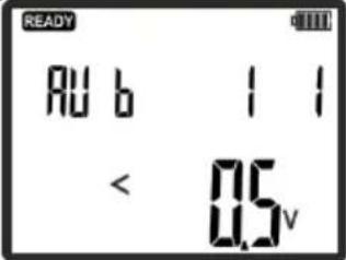 | ||
| 5 |  or set the required signal level. or set the required signal level. | In the circuit, the current signal is forced with a value equal to the level of:1 = 10mA2 = 20mA3 = 40mA4 = 80mA (limited working time *)5 = 160mA (limited working time *) | ||
| 6 | Connect one of the banana sockets of the transmitter to the one opening of the wall outlet. | Fig. 30 | ||
| 7 | Connect the second banana socket of the transmitter to the second opening of the wall outlet. | Fig. 30 | ||
| 8 | START Start the transmission. | Flashing LED:green - correctly selected mode.red - incorrectly selected mode. | ||
| Receiver: | ||||
| 9 | Turn the receiver ON. | |||
| 10 | Pressing the button set FUSE mode. | FUSE | ||
| 11 | Move the head of the receiver along the tested switchboard. When a protection device is detected, the receiver will generate a sound signal and activate the flashlight. | Fig. 30 | ||
* - transmission level 80mA and 160mA at network voltage of 230V AC cause rapid heating of the transmitter circuits and its blockade lasting until they cool down.
5.6 Routing a cable line – Power mode "Pr"
Routing a cable line is possible with "Pr" power mode. The transmitter should be connected to the cable line in a manner allowing current to flow through the tested object - Fig. 31. In order to increase the range of tested line, minimize the mutual cancelling of vectors of magnetic fields generated around the input and output currents of the transmitter. The impact of the resulting magnetic fields may be minimized by introducing the transmitter signal to the two ends of the routed line. This method requires the use of additional extension cord connected to the second end of the line - Fig. 32. Connection shown in Fig. 32 increases the locating range and accuracy. Additional cable must be laid at a distance exceeding 5-times the expected depth of the cable. The location capabilities of the set are confirmed for the line with a length of 500m , installed in a depth of 2 meters. For routing the cable lines and determine e.g. the depth of installing the cables, use dedicated for this purpose locators manufactured by Sonel S.A.
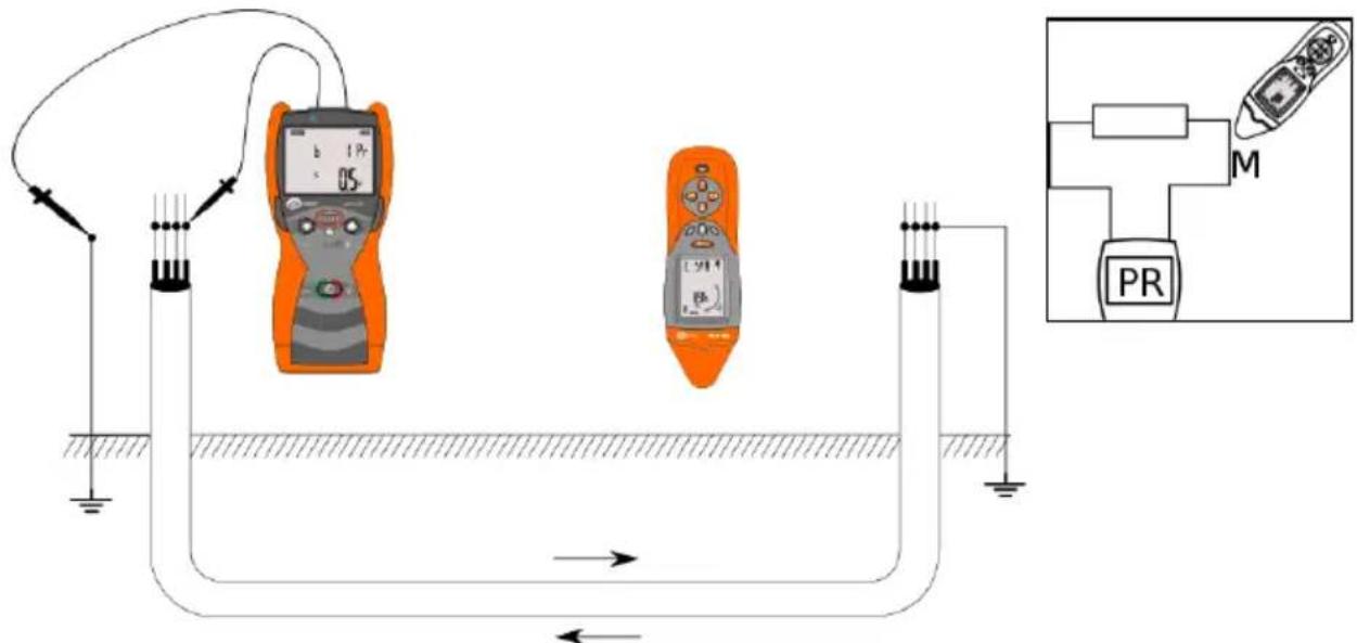
Fig. 31 Locating cables in power mode with shorted cores of the cable.
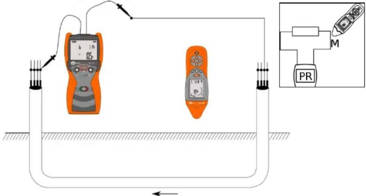
Fig. 32 Locating cables in Power mode using an external cable.
The procedure for routing cable lines:
| No. | Operation | Screen / Comments | |
| Transmitter: | |||
| 1 | At both ends of the tested cable line short all conductors. | Fig. 31 | |
| 2 | In the absence of an extension cord, connect one end of the cable line to the ground. | Fig. 32 | |
| 3 |  Turn the transmitter ON. Turn the transmitter ON. | 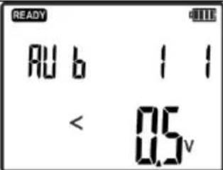 | |
| 4 | Connect one of the banana sockets of the transmitter to one end of the analysed cable. | Fig. 31 | |
| 5 | Connect the second banana socket of the transmitter to the other end of the analysed cable or to the ground. | Fig. 31 or Fig. 32 | |
| 6 |  Press and hold until the screen with settings is displayed. Press and hold until the screen with settings is displayed. | 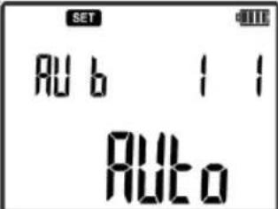 | |
| 7 |  set the Power mode - Pr. set the Power mode - Pr. | 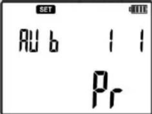 | |
| 8 |  Start the transmission. Start the transmission. | Flashing LED:green - correctly selected mode.red - incorrectly selected mode. | |
| Receiver: | |||
| 9 |  Turn the receiver ON. Turn the receiver ON. | ||
| 10 |  Press the button and set current mode - CAbL. Press the button and set current mode - CAbL. | 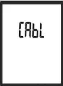 | |
| 11 | Direct the head of the receiver towards the highest value of the signal level to locate the cable. | 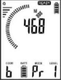 | |
| 12 |  Press the button to switch the receiver into 3D mode.Locate the cable line as indicated on the receiver screen.Description of individual screens is presented in sec. 5.1.1 Press the button to switch the receiver into 3D mode.Locate the cable line as indicated on the receiver screen.Description of individual screens is presented in sec. 5.1.1 | 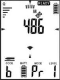 | |
| 13 | Move the head of the receiver along the traced line, following the maximum signal strength. | Fig. 31 or Fig. 32 | |
In case of exceeding the maximum power of the transmitted signal, the transmitter will turn off the transmission and enters the status of the electronic fuse. The transmitter will display the following warning screen:
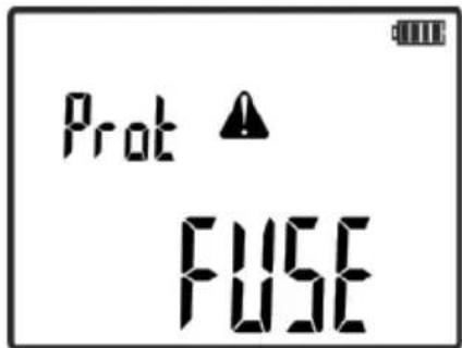
In such case, press START button in order to acknowledge the electronic fuse and decrease the transmission level or use "UI" mode for routing the cable lines, as it has the forced current transmission, which is fixed and controlled by signal level.
5.7 Locating non-conductive pipes
With an additional conductive wire, the system may be used for routing and locating non-conductive pipes. The transmitter should be connected to the wire in a manner enabling the use of current signal in "UI" mode. See example in Fig. 33.
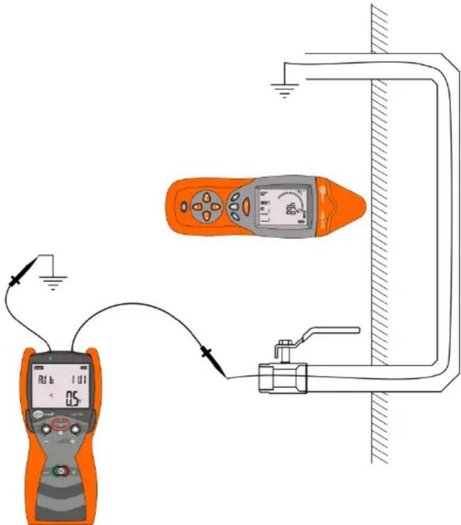
Fig. 33 Tracing electrically non-conductive hydraulic system.
5.8 Phase identification
Phase identification involves determining the phase in the circuit with respect to the reference circuit.
Note: The system is working properly within the radio communication range.
The transmitter with a specific phase must be connected to the tested circuit with the selected operating mode P3. The circuit with the transmitter will be a reference for the phase identification in other circuits.
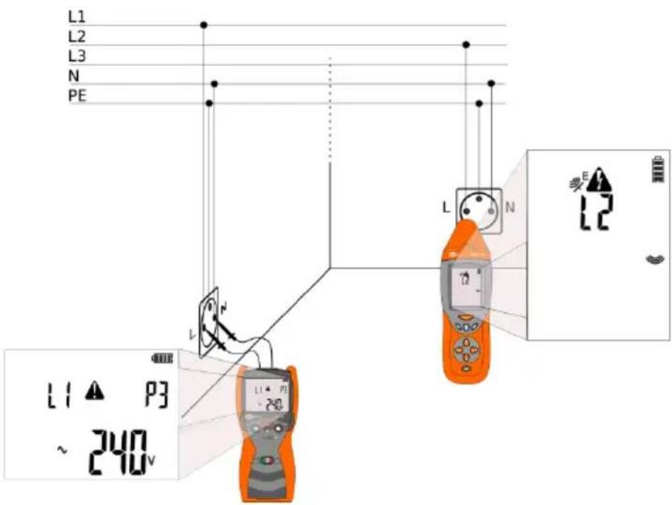
Fig. 34 Phase identification.
| No. | Operation | Screen |
| Transmitter: | ||
| 1 |  Turn the transmitter ON. Turn the transmitter ON. |  |
| 2 | Connect "L" socket of the transmitter to "L" opening of the wall outlet. | Fig. 34Determining which opening of the wall outlet is phase may be carried out using NEON mode of the receiver. |
| 3 | Connect the second banana socket of the "N" transmitter to the second opening of the "N" wall outlet. | Fig. 34Determining which opening of the wall outlet is phase may be carried out using NEON mode of the receiver. |
| 4 |  Press and hold until the screen with settings is displayed. Press and hold until the screen with settings is displayed. | 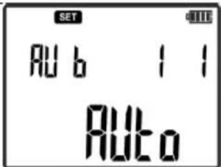 | ||
| 5 |  or select P3 mode. or select P3 mode. | 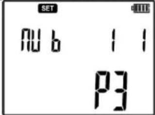 | ||
| 6 |  Confirm. Confirm. | 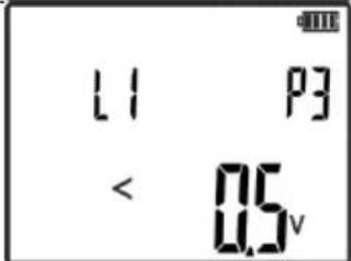 | ||
| 7 |  or set the desired reference phase of the connected circuit. or set the desired reference phase of the connected circuit. | Available marking of phases:L1, L2, L3. | ||
| Receiver: | ||||
| 8 |  Turn the receiver ON. Turn the receiver ON. | |||
| 9 |  Set P3 mode. Set P3 mode. | |||
| 10 | Place the receiver close to the tested circuit to determine its phase. | Fig. 34 | ||
5.9 "Neon" mode
The "Neon" mode in the receiver is used to detect the sources of electric field with frequency of 50 Hz...60 Hz - Fig. 35. Use this mode to identify the phase conductors that generate the electric field. This mode is used with active power supply of the electrical system.
In this mode, the screen of the receiver shows a bar graph and a value proportional to the electric field strength.
When the signal level is too high, you may use the relative mode by pressing ABS/REL button - see sec. 2.2.3.6. Hold this key to exit the relative mode.

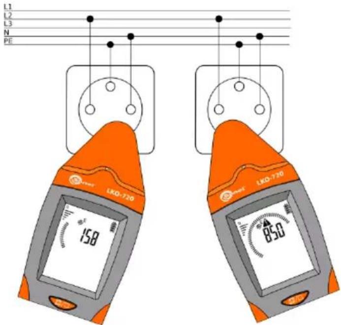
Fig. 35 Detecting electric field.
Note: Metal, ungrounded elements located in the alternating electric field cause inaccurate readings of the detected electric field.
Procedure of activating "NEON" mode.
| No. | Operation | Screen | |
| Receiver: | |||
| 1 |  Turn the receiver ON. Turn the receiver ON. | ||
| 2 |  Set Neon mode. Set Neon mode. | 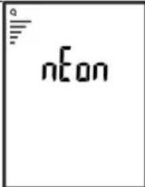 | |
| 3 | Approach the receiver to the tested object in order to determine whether it is a source of alternating electric field. | Fig. 35 | |
5.10 Multi-transmitter operation
LKZ enables operation work with four transmitters at the same time. Each transmitter must be synchronized with the receiver and have a specific code of the transmitted signal set to uniquely identify the transmitter (A, B, C, D). When it is necessary, the synchronization of transmitters with the receiver is carried out in accordance with sec 3.3.
The multi-transmitter operation of the system enables precise location of breaks in an electric system and identify individual cores in the cable.
5.10.1 Multi-transmitter operation – locating breaks
The transmitters should be connected to two ends of an open circuit. Each of the transmitters should be assigned with a specific code of the transmitted signal and the voltage mode set for the transmitted signal. The place of detected break will be indicated on the receiver by changes in the received signal code.
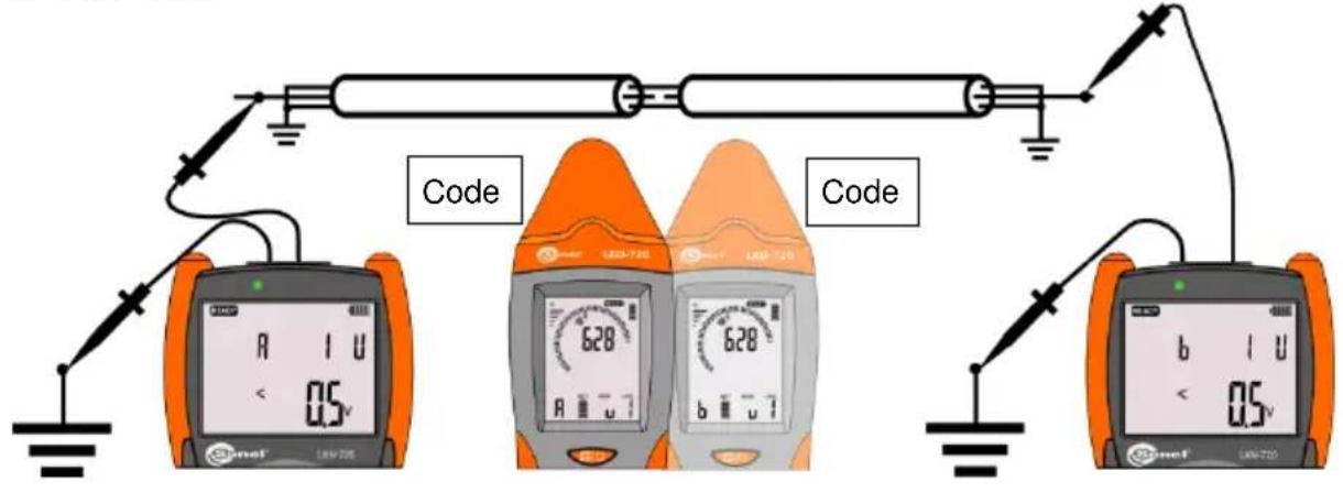
Fig. 36 Locating breaks – multi-transmitter mode.
The procedure of detecting a break in an open circuit for two transmitters synchronized with the receiver (synchronization sec. 3.3).
| No. | Operation | Screen |
| 0 | Make sure that the tested circuit is not energized. It is essential to remove the voltage source from the circuit. | |
| Transmitter 1: | ||
| 1 |  Turn the transmitter ON. Turn the transmitter ON. | 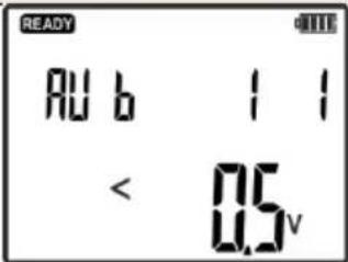 |
| 2 | Connect the banana socket to the end of tested circuit. | Fig. 36 |
| 3 | Connect the second banana socket of the transmitter to grounding. | Fig. 36 |
| 4 |  Press and hold until the screen with settings is displayed. Press and hold until the screen with settings is displayed. | 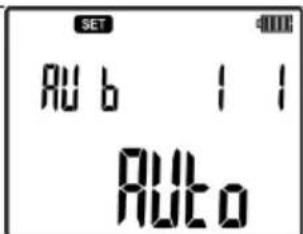 | ||
| 5 |  select SET mode. select SET mode. | 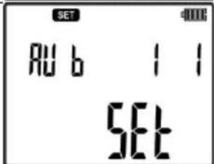 | ||
| 6 |  Confirm. Confirm. | |||
| 7 |  select CODE. select CODE. | 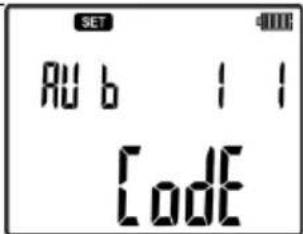 | ||
| 8 |  Confirm. Confirm. | |||
| 9 |  select the code signal for the transmitter A, B, C or D. select the code signal for the transmitter A, B, C or D. | 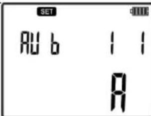 | ||
| 10 |  Confirm. Confirm. | |||
| 11 |  Press and hold until the screen with settings is displayed. Press and hold until the screen with settings is displayed. | 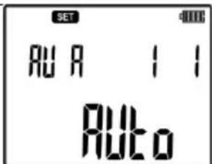 | ||
| 12 |  select U mode. select U mode. | 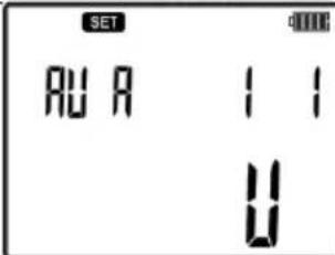 | ||
| 13 |  Confirm. Confirm. |  | ||
| 14 | STARTStart the transmission. | |||
| Transmitter 2: | ||||
| Repeat steps 1 - 14. | ||||
| Receiver: | ||||
| 15 |  Turn the receiver ON. Turn the receiver ON. | |||
| 16 | Pressing the key set voltage mode uAnt. |  | ||
| 17 | Following the signal value and the transmitted code, move the receiver on the path of maximum signal. Changed code indicates a potential break in the circuit. | Fig. 36 | ||
5.10.2 Multi-transmitter operation – identifying cores in a multicore cable
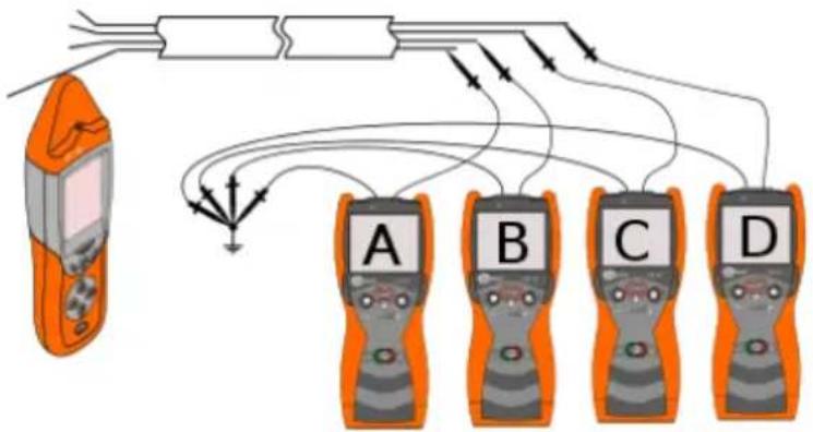
Identifying cores in a multicore cables is possible in the voltage mode (Fig. 38), current mode and voltage-current mode (Fig. 37). Approaching the receiver closely to the cable core improves the precision of indications based on the code signal.
In the multi-transmitter operation, each transmitter should be set with a different code of the transmitted signal, choosing from the four available codes: A, B, C, D.
In the voltage mode, the cores that are not connected to the transmitters should be grounded (Fig. 38). In order to achieve clarity in identifying cable cores, use the contact probe connected to the receiver.
In the current mode, the proximity of cores may cause an incorrect reading of the transmitted code by the receiver and a wrong identification. Increasing the selectivity may be achieved by using a non-contact probe or by unambiguous identification of cores by C-8 and C-3 measurement clamps.
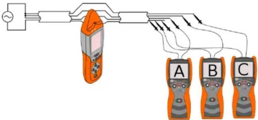
flowchart
graph TD
    A["Power Source"] --> B["Mobile Phone"]
    B --> C{Signal Path}
    C --> D["A Device"]
    C --> E["B Device"]
    C --> F["C Device"]
    D --> G["Output"]
    E --> G
    F --> G
Fig. 37 Identifying cores in the cable – mode I.
flowchart
graph TD
    A["Orange mobile phone"] --> B["Switch"]
    B --> C["Device 1"]
    B --> D["Device 2"]
    B --> E["Device 3"]
    B --> F["Device 4"]
    C --> G["Output Signal"]
    D --> G
    E --> G
    F --> G
Fig. 38 Identifying cores in the cable – mode U.
The transmitters should be connected as shown in Fig. 37 or Fig. 38. Each of the transmitters should have a characteristic code of the transmitted signal - A, B, C or D and the voltage mode set as shown in Fig. 38 or the current mode set as shown in Fig. 37. The receiver, depending on the selected mode, should be set appropriately in "uAnt" mode for the voltage mode or in "3D" for the current mode.
Identifying cores in the cable – mode U.
| No. | Operation | Screen |
| 0 | Make sure that the tested circuit is not energized. | |
| Transmitter 1: | ||
| 1 |  Turn the transmitter ON. Turn the transmitter ON. | 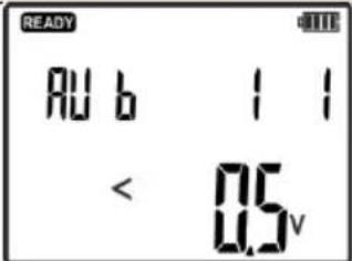 |
| 2 | Connect of the banana sockets to the end of tested circuit. | Fig. 38 |
| 3 | Connect the second banana socket of the transmitter to grounding. | Fig. 38 |
| 4 |  Press and hold until the screen with settings is displayed. Press and hold until the screen with settings is displayed. | 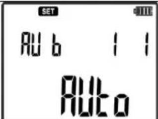 |
| 5 |  select SET mode. select SET mode. | 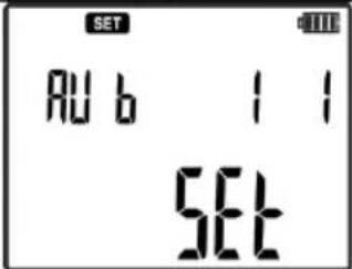 |
| 6 |  Confirm. Confirm. | |
| 7 |  select CODE. select CODE. | 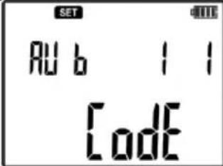 | ||
| 8 |  Confirm. Confirm. | |||
| 9 |  select the code signal for the transmitter A, B, C or D. select the code signal for the transmitter A, B, C or D. | 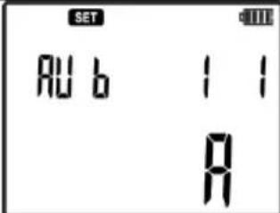 | ||
| 10 |  Confirm. Confirm. | |||
| 11 |  Press and hold until the screen with settings is displayed. Press and hold until the screen with settings is displayed. | 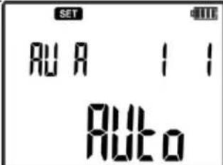 | ||
| 12 |  select U mode. select U mode. | 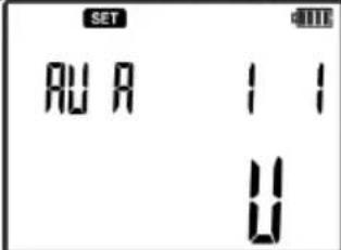 | ||
| 13 |  Confirm. Confirm. | |||
| 14 |  Start the transmission. Start the transmission. | |||
| Transmitter X (X = 2...4): | ||||
| Repeat steps 1 - 14. | ||||
| Receiver: | ||||
| 15 |  Turn the receiver ON. Turn the receiver ON. | |||
| 16 |  Pressing the key, set voltage mode uAnt. Pressing the key, set voltage mode uAnt. |  | ||
| 17 | Move receiver closer to the individual wires to identify them by the displayed code. | Fig. 38 | ||
Remember to set different codes A, B, C or D in the transmitters.
Identifying cores in the cable – mode I or UI.
| No. | Operation | Screen | |
| Transmitter 1: | |||
| 1 | Turn the transmitter ON. | 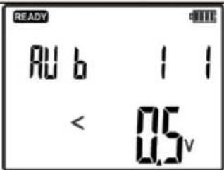 | |
| 2 | Connect "L" banana socket of the transmitter to the end of tested circuit. | Fig. 37 | |
| 3 | Connect the second banana socket "N" of the transmitter to grounding. | Fig. 37 | |
| 4 | Press and hold until the screen with settings is displayed. | 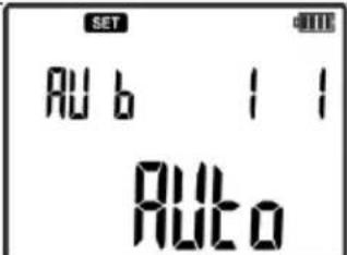 | |
| 5 | or select SET mode. | 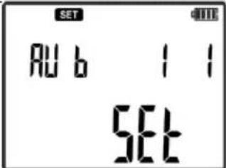 | |
| 6 | START Confirm. | ||
| 7 | or select CODE. | 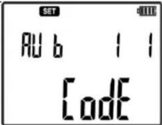 | |
| 8 | START Confirm. | ||
| 9 | or select the code signal for the transmitter A, B, C or D. | 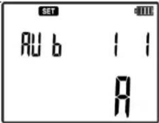 | |
| 10 | START Confirm. | ||
| 11 | [START]Press and hold until the screen with settings is displayed. | 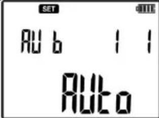 | ||
| 12 |  select I or UImode, depending on whether the tested conductor is connected to the power supply or not. select I or UImode, depending on whether the tested conductor is connected to the power supply or not. | 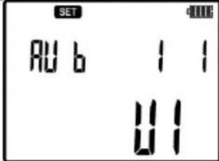 | ||
| 13 |  Confirm. Confirm. | |||
| 14 |  Start the transmission. Start the transmission. | |||
| Transmitter X (X = 2...4): | ||||
| Repeat steps 1 - 14. | ||||
| Receiver: | ||||
| 15 |  Turn the receiver ON. Turn the receiver ON. | |||
| 16 |  Press the button and set current mode - IAnt. Press the button and set current mode - IAnt. | 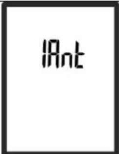 | ||
| 17 | Move receiver closer to the individual wires to identify them by the displayed code. | Fig. 37 | ||
6 Accessories
6.1 Transmission clamps
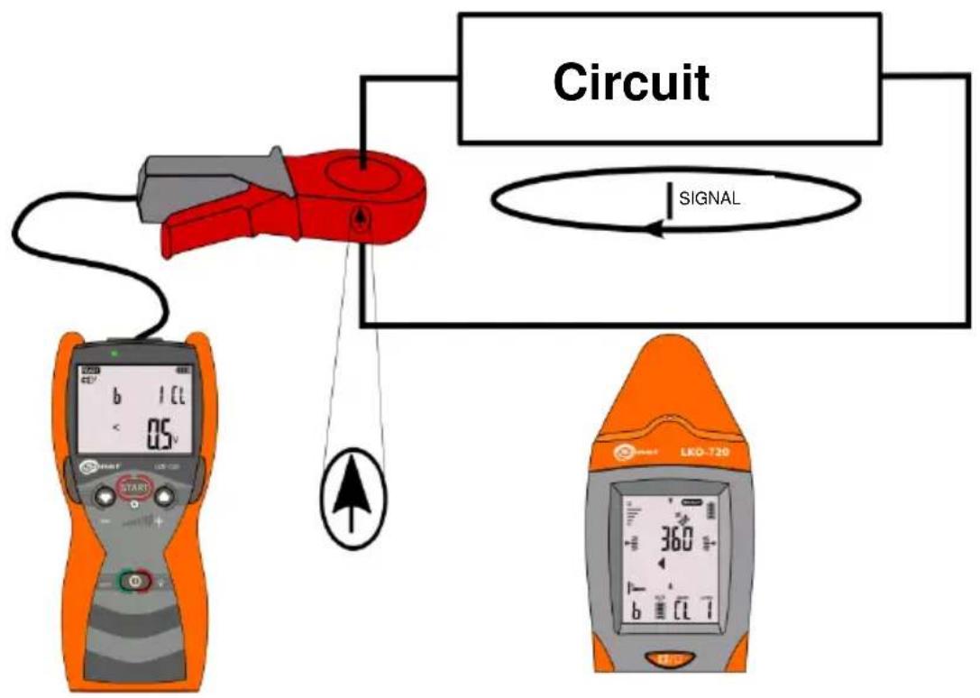
Transmission clamps N-1 are used for locating and routing closed circuits that cannot be opened. These clamps may be used both in circuits with current flow (up to 15A AC) and in systems without the current flow (no voltage) - Fig. 39.
Remember that the current value in the tested system of 50/60Hz must not cause the saturation of clamps (in such case characteristic buzz is heard in the clamps).
Transmission clamps enable forcing current in objects with a diameter up to 52mm.
If possible, fix the clamps on a multi-core cable, not on the individual cores (conductors).
flowchart
graph TD
    A["Start: 0.5V digital display"] --> B["Circuit: 360V"]
    B --> C["SIGNAL: 100% signal output"]
    D["End: LKO-720 digital display"] --> E["Signal flow path"]
    style A fill:#f9f,stroke:#333
    style D fill:#f9f,stroke:#333
    style B fill:#ccf,stroke:#333
    style C fill:#cfc,stroke:#333
Fig. 39 Transmission clamps – current forcing in detected circuit.
The arrow shown in the drawing, marked on the housing of clamps, indicates the direction of the forced current. The receiver in 3D mode, uses respective symbols to indicate the same direction.
The procedure for setting the transmitter with transmission clamps:
| No. | Operation | Screen | |
| Transmitter: | |||
| 1 | Turn the transmitter ON. | 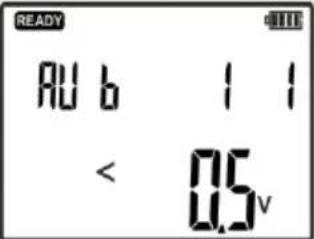 | |
| 2 | Connect "L" banana socket to "H" socket of transmission clamps N-1. | Fig. 39Direction of the transmitted signal in accordance with the graphical depiction on the clamps. | |
| 3 | Connect "N" banana socket to "E" socket of transmission clamps N-1. | ||
| 4 | Press and hold until the screen with settings is displayed. | 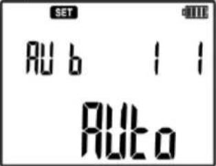 | |
| 5 | select transmission clamps mode CLP. | 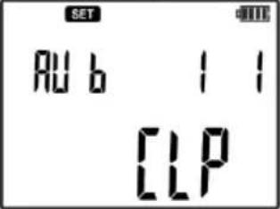 | |
| 6 | Confirm. | 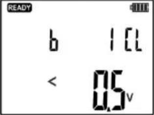 | |
| 7 | set one of three transmission levels. | ||
| 8 | Start the transmission. | ||
| Receiver - current mode M / 3D: | |||
| 9 | Turn the receiver ON. | ||
| 10 | Press the button and set current mode - IAnt. | 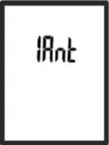 | |
| 11 | Direct the head of the receiver towards the highest value of the signal level to locate the conductor. | 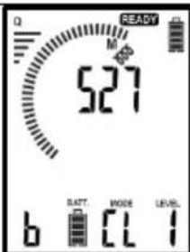 | ||
| 12 |  Press the button to switch the receiver into 3D mode.Locate the cable as indicated on the receiver screen.Description of individual screens is presented in sec. 5.1.1. Press the button to switch the receiver into 3D mode.Locate the cable as indicated on the receiver screen.Description of individual screens is presented in sec. 5.1.1. | 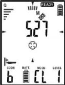 |
6.2 Reception clamps
Reception clamps (C-8 and C-3) are used in the current mode or in other mode forcing current, in order to uniquely identify wire or cable with a forced current signal.
Reception clamps should be connected to the socket on the receiver's head. During operation of the receiver, when the direction of the arrow on the housing of clamps is compatible with the direction of the transmitted signal, i.e. it indicates the location of connecting "L" banana sockets of the transmitter, the display of the receiver shows "OK" Fig. 40. The receiver automatically detects that reception clamps have been plugged into the receiver, which is indicated by displaying 'clamps' icon.
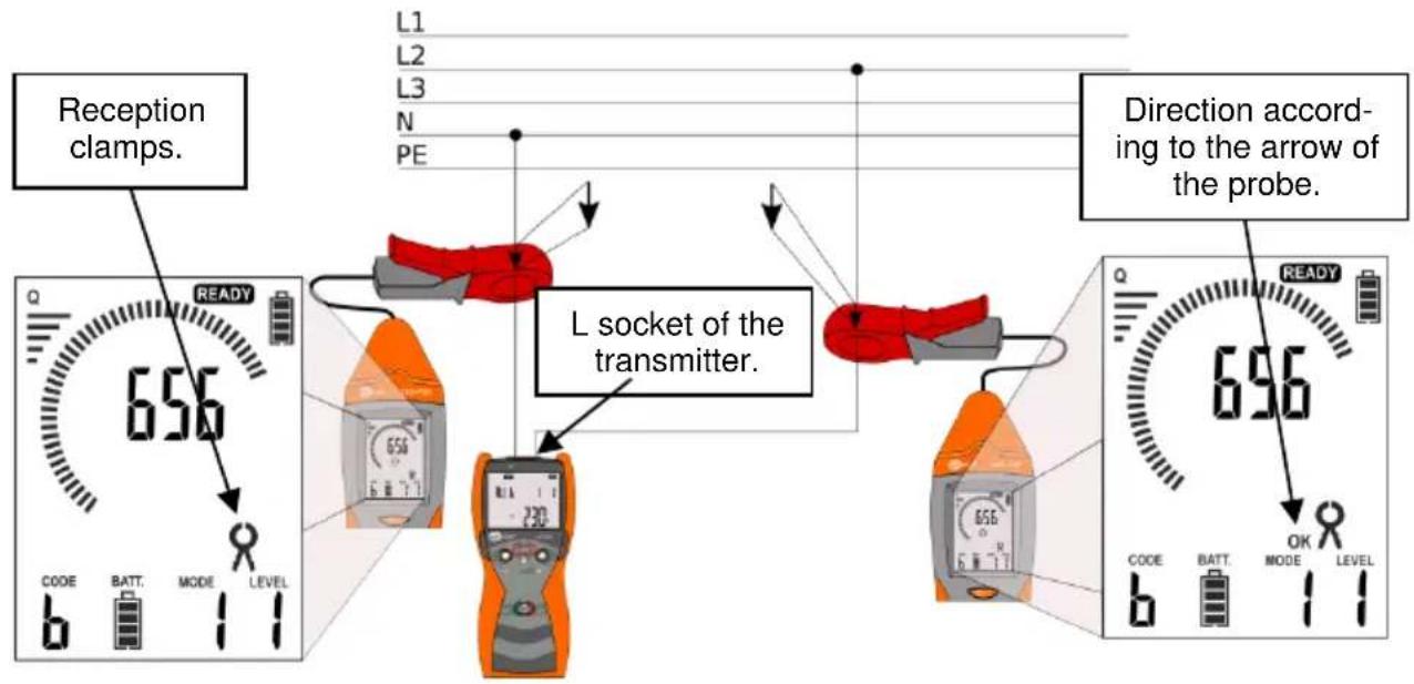
Fig. 40 Reception clamps – current forcing in detected circuit.
6.3 Contact probe
The contact probe is used to uniquely identify conductors in places difficult for using only the receiver. After plugging the contact probe, the receiver may operate in three modes: NEON, P3, and main CP. After plugging the probe in, the internal detectors of the receiver are excluded from the measurement path.
CP mode means contact probe mode of the electric field uAnt of the receiver. This mode may be used, e.g. for identifying a conductor.
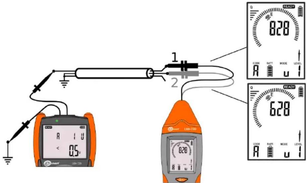
Fig. 41 Contact probe – identifying conductors.
The contact probe may be used in all circuits using "U" mode for identification. Fig. 41 shows an example of identifying cores in a multicore wire. The transmitter is connected to the tested core in the voltage mode "U", while the other cores are grounded. The higher value displayed in the receiver uniquely identifies the core.

natural_image
Two metallic electrical probes with threaded ends, one upright and one straight (no text or symbols visible)Fig. 42 Contact probe must be used with a blade probe or a crocodile clip.
6.4 Non-contact probe
The non-contact probe is used in the case of difficult access to the tested wire or cable lines, for security reasons or inability to use the contact probe. The non-contact NCP probe is designed to operate in current mode and is used to detect the transmitted signal in a magnetic field. An example is shown in a Fig. 43 and with multi-transmitter operation in Fig. 43.
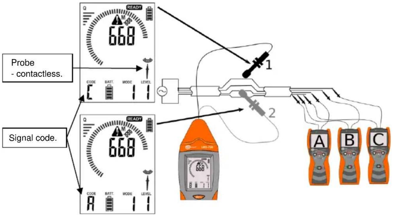
Fig. 43 Non-contact probe – identifying conductors during multi-transmitter operation.
Connecting the non-contact probe is automatically detected by the receiver and indicated by the pictogram on the receiver screen. After plugging the probe in, the internal detectors of the receiver are excluded from the measurement path.
Marking on the probe is used to identify the direction of the transmitted signal. Arrows marked on the probe housing show the "L" clip of the transmitter plugged in the tested circuit Fig. 44. Positioning the probe in the direction of the transmitted signal is indicated on the receiver screen by "OK" symbol.
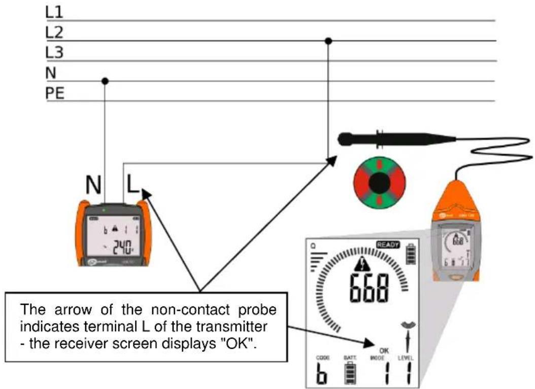
Fig. 44 Non-contact probe - the identification of the terminal L of the transmitter.
6.5 Headphones
The headphones are used in places where user has difficulties to receive buzzer signals and messages concerning the tested or identified objects.
Connected headphones are automatically detected by the receiver, which is indicated on the receiver display.
7 Software update
Current versions of the software for the transmitter and receiver are available on the manufacturer's website. Before updating the device software, prepare USB cable to connect the receiver to a PC. The cable should be equipped with a mini-A USB plug.
Install the updating software on your computer according to the prompts displayed on its screen. Updating of the transmitter is performed by the radio path between the receiver and the transmitter. The distance between the receiver and the transmitter should not be greater than 0.5m.
The transmitter should be disconnected from the measuring circuit. The receiver and transmitter should be fitted with power sources enabling their longer operation. Indicators of battery charge status of the transmitter and the receiver should show at least 3 bars.
Make sure that your computer has a stable source of power supply. When PC is connected to mains, it is recommended to use UPS. If a portable computer is used for the update, make sure that the batteries are sufficient for at least one-hour operation.
The receiver must be connected via a USB cable to the PC. The device should be detected. If this is the first time of connecting LKO to connect to the computer, you may need to install drivers.
The procedure for activating the update mode in the transmitter and receiver.
| Receiver - activating the software update mode: | |||
| 1 | Connect the receiver to your PC using a USB cable | ||
| 2 | 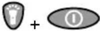 Press FLASHLIGHT button and simultaneously press ON/OFF button. Press FLASHLIGHT button and simultaneously press ON/OFF button. | 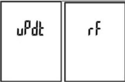 | |
| Transmitter - activating the firmware update mode: | |||
| 3 |  Turn the transmitter ON. Turn the transmitter ON. | 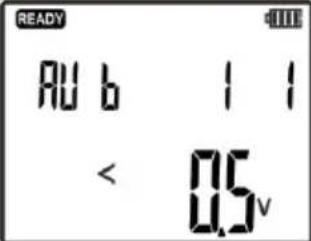 | |
| 4 |  Press and hold until the screen with settings is displayed. Press and hold until the screen with settings is displayed. | 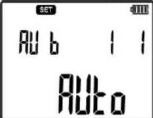 | |
| 5 |   oIselect SET mode. oIselect SET mode. | 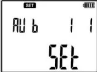 | ||
| 6 |  Confirm. Confirm. | |||
| 7 |  or select UPDT. or select UPDT. | 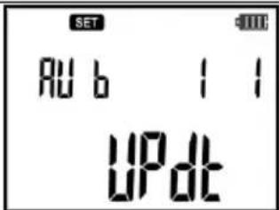 | ||
| 8 |  Approveor Approveor cancel. cancel. | 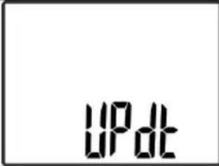 | ||
When you turn on the transmitter and receiver into the software update mode, follow the prompts of the update program, displayed on the screen.
Any communication errors that may occur when performing the transmitter software update are indicated by messages on the screens of the receiver, transmitter and PC.
| Message | Information | |
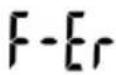 | Damage detected in firmware of LKO device. It is necessary to update software again. | |
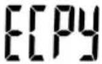 | Message displayed during the auto-repair of the applications installed in LKN transmitter.Note: Restoring the operating software. Do not turn off the device. | |
7.1 Restoring firmware version 1.00
LKN-720 has the ability to restore its firmware in version 1.00. Before software restoring prepare a thin wire (e.g. a paper clip) with a diameter of 1.5mm and length at least 4cm. The device should be disconnected from the tested circuit and switched off. Remove the battery cover, locate the row of 5 openings. Insert the wire into the first opening from the top of the transmitter and press the button for
restoring software, which is inside the opening, at the same time start the transmitter with ton.

Correct restoring will be indicated on the screen of the transmitter by the following messages:
ECP4 and UFP4 after completing the software downloading process, the device is switched on again.
8 Cleaning and maintenance
CAUTION! Use only the maintenance methods specified by the manufacturer in this manual.
The casing of the set may be cleaned with a soft, damp cloth using all-purpose detergents. Do not use any solvents or cleaning agents which might scratch the casing (powders, pastes, etc.).
Cables should be cleaned with water and detergents, and then dried.
9 Storage
During the storage of the set, the following recommendations must be observed:
- disconnect all the leads from the transmitter.
- clean the transmitter, receiver and all accessories thoroughly.
- If transmitter and receiver and are to be stored for a prolonged period of time, the batteries must be removed from them.
- In order to prevent a total discharge of the rechargeable batteries in the case of a prolonged storage, charge them from time to time.
10 Dismantling and disposal
Worn-out electric and electronic equipment should be gathered selectively, i.e. it must not be placed with waste of another kind.
Worn-out electronic equipment should be sent to a collection point in accordance with the law of waste electrical and electronic equipment or local regulations.
Before the equipment is sent to a collection point, do not dismantle any elements.
Observe the local regulations concerning disposal of packages and used batteries/rechargeable batteries.
11 Technical specifications
The device does not have the character of a standard and therefore is not subject to calibration. The proper form of control for this type of instrument is checking.
a) insulation type of the transmitter .... double, according to EN 61010-1
b) measurement category of the transmitter ....III 600V acc. to EN 61010-1
c) degree of housing protection of the transmitter acc. to EN 60529 IP67
d) degree of housing protection of the receiver acc. to EN 60529 IP40
e) power supply of the transmitter: .alkaline batteries or NiMH rechargeable batteries size AA (4 pcs)
f) receiver power supply 6LR61 9 V alkaline battery
g) maximum operating voltage of the transmitter 500 V RMS (707 V ampl)
h) maximum operating voltage of the contact probe CP 500 V RMS (707 V ampl)
i) transmitter dimensions ...... (length x width x depth) 221 x 102 x 62 mm
j) the weight of the transmitter.... approx. 0.7 kg
k) receiver dimensions ...... (length x width x depth) 245 x 77 x 52 mm
I) receiver weight .... approx. 0.4 kg
m) operating temperature: -10..+50°C
n) storage temperature ....-20°C...+60°C
o) reference temperature....+23 ± 2°C
p) maximum depth of the analysed object (current mode)....2 m
q) maximum range for the length of the analysed object (current/power mode)....500 m
r) the maximum distance from the tested object for the non-contact neon probe: .... in air = 0.5 m
......in concrete = 0.05 m
s) quality standard, ...... design and manufacturing are ISO 9001 compliant
t) the product meets EMC requirements (immunity for industrial environment) according to the following standards:
EN 61326-1 and EN 61326-2-2
Note: The transmitter may produce interference with values exceeding allowable limits defined in EN 61326-1 and cause interference in other devices when connected to the mains.
12 Manufacturer
The manufacturer of the device and provider of guarantee and post-guarantee service:
SONEL S.A.
Wokulskiego 11
58-100 Šwidnica
Poland
tel. +48 74 884 10 53 (Customer Service)
e-mail: customerservice@sonel.com
web page: www.sonel.com
Note:
Service repairs must be performed only by the manufacturer.
NOTES
NOTES
NOTES
SONEL S.A.
Wokulskiego 11
58-100 Świdnica
Poland
Customer Service
tel. +48 74 884 10 53
e-mail: customerservice@sonel.com
www.sonel.com
- TABLE OF CONTENTS
- Safety 5
- Description of the system....6
- Principle of system operation 15
- Operation....23
- Measurements....29
- Accessories....60
- Software update....66
- Cleaning and maintenance 68
- Storage....68
- Dismantling and disposal 68
- Technical specifications ....69
- Manufacturer 69
- Safety
- CAUTION!
- WARNING:
- Note:
- Description of the system
- Transmitter LKN-720
- Front panel
- LCD Display
- Operation
- Turning the power ON
- Turning the power OFF
- Selecting the operating mode or entering the transmitter settings
- Switching the transmitted signal ON - OFF
- Switching LCD display ON and selecting its backlight brightness.
- LKO-720 receiver
- Front panel
- Display
- Operation
- Switching the receiver ON
- Switching the receiver OFF
- Selecting the operating mode of the receiver
- f) Operating mode FUSE
- Changing the sound signal.
- Adjusting the sound signal strength
- Changing the displayed value of signal strength in relation to signal reference value
- Receiver settings.
- Switching and adjusting backlight brightness.
- Turning the flashlight ON and OFF
- Principle of system operation
- Transmitter LKN-720
- Receiver LKO-720
- Synchronization of the transmitter with the receiver.
- Modes of system operation
- Current mode I
- Voltage-current mode UI
- Mode of detecting P3 phase
- Power mode - Pr
- Note
- The mode of detecting safety devices - FUSE
- Clamp mode - CL
- Mode for detecting 50Hz/60Hz electric field - NEON
- Operation in IT networks
- Operation
- Replacing the power supply
- Receiver
- Transmitter
- Energy-saving function: AUTO-OFF
- Transmitter
- Receiver
- Setting audio path gain.
- Setting the transmitter code
- Measurements
- Detecting cables in ceilings, walls and floors
- Live cables
- Conductors without voltage
- Voltage-current mode UI
- Locating breaks in cables
- Identification of cables
- In the analysed cable:
- In other cables:
- Locating short-circuits in multicore cables
- Identifying fuses in a switchboard
- Routing a cable line – Power mode "Pr"
- Locating non-conductive pipes
- Phase identification
- "Neon" mode
- Multi-transmitter operation
- Multi-transmitter operation – locating breaks
- Multi-transmitter operation – identifying cores in a multicore cable
- Accessories
- Transmission clamps
- Reception clamps
- Contact probe
- Non-contact probe
- Headphones
- Software update
- Restoring firmware version 1.00
- Cleaning and maintenance
- Storage
- Dismantling and disposal
- Technical specifications
- Manufacturer
Brand : Sonel
Model : LKZ-720
Category : Detector