LKZ-2500 Start - Detector Sonel - Free user manual and instructions
Find the device manual for free LKZ-2500 Start Sonel in PDF.


| Product Type | Cable and underground infrastructure locator system (LKD-2500 detector) |
| Dimensions (LKD-2500) | 290 x 275 x 100 mm |
| Weight (LKD-2500) | 1.2 kg |
| Power Supply (LKD-2500) | Li-Ion rechargeable battery 3.6 V, 6.7 Ah |
| Operating Time (LKD-2500) | Up to 13 hours |
| Charging Interface (LKD-2500) | USB-C 5 V / 3 A |
| Charging Time (LKD-2500) | Max 4 hours |
| Ingress Protection (LKD-2500) | IP65 |
| Wireless Communication | Bluetooth 5.0 BLE, range up to 50 m |
| Auto-Off Time (LKD-2500) | 5 minutes after loss of Bluetooth connection |
| Signal Reception Methods | Narrow, Wide, Selective |
| Operating Modes | Passive (Power, Radio) and Active (Signal) |
| Depth Measurement Accuracy | Up to 2.5% of measured value (Signal mode, 32 kHz, depth ≤1 m) |
| Operating Temperature | -10°C to +50°C |
| Storage Temperature | -20°C to +60°C |
| Safety Classification (Transmitter LKN-2500) | Double insulation, CAT II 300 V |
| Fuse Specification (Transmitter) | 5 x 20 mm, 0.5 A / 250 V AC, fast-acting |
| Maintenance | Clean casing with soft damp cloth and mild detergent; clean probe with water and dry |
| Quality Standard | ISO 9001 compliant |
| EMC Compliance | EN 61326-1, EN 61326-2-2 (industrial environment) |
Frequently Asked Questions - LKZ-2500 Start Sonel
User questions about LKZ-2500 Start Sonel
0 question about this device. Answer the ones you know or ask your own.
Ask a new question about this device
Download the instructions for your Detector in PDF format for free! Find your manual LKZ-2500 Start - Sonel and take your electronic device back in hand. On this page are published all the documents necessary for the use of your device. LKZ-2500 Start by Sonel.
USER MANUAL LKZ-2500 Start Sonel
natural_image
Product photo of a neI® self-checkout measurement device with open case, digital display, and stand (no visible text or symbols)USER MANUAL
CABLES AND UNDERGROUND INFRASTRUCTURE LOCATOR
LKZ-2500
LKN-2500 • LKD-2500 • SONEL LKZ MOBILE
LKN-2500
LKD-2500
USER MANUAL
CABLES AND UNDERGROUND INFRASTRUCTURE LOCATOR
LKZ-2500
LKN-2500 • LKD-2500 • SONEL LKZ MOBILE

SONEL S.A.
Wokulskiego 11
58-100 Świdnica
Poland
LKZ-2500 is a modern, high quality measuring system, easy and safe to use. Reading and using of this manual will help to avoid errors in measurements and prevent possible problems when operating the instrument.
CONTENTS
1 General information....5
1.1 Safety symbols....5
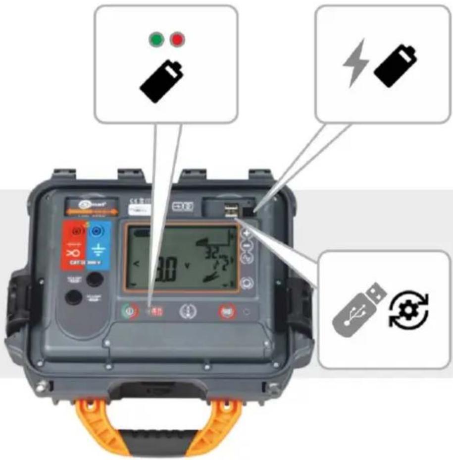
1.2 Behaviour of signalling LEDs 5
1.3 Safety 6
2 Quick start 7
3 Description of the system....8
3.1 Main features of the system 8
3.2 Principle of system operation 8
3.3 Transmitter LKN-2500....9
3.3.1 Buttons on the housing....9
3.3.2 Display....10
3.3.3 Time settings for automatic shutdown (auto-off) 11
3.4 LKD-2500 Detector 11
3.4.1 Buttons on the housing....11
3.4.2 Handles....12
3.5 Sonel LKZ Mobile application.... 13
3.5.1 Gestures 13
3.5.2 Menu icons 13
3.5.3 Measurements 15
3.5.4 Bluetooth....15
3.5.5 Settings....15
3.5.6 Creating a memory structure....16
4 Pairing devices....17
5 Routing 18
5.1 Routing screen of the Sonel LKZ Mobile application.... 18
5.2 Methods of signal reception 20
5.3 Routing modes....20
5.3.1 Operation in passive mode - Power....20
5.3.2 Operation in passive mode – Radio....21
5.3.3 Working in active mode – Signal 22
5.4 Route registration....26
5.5 Restoring the route....28
6 Software update....30
6.1 LKN-2500 transmitter 30
6.2 LKD-2500 Detector 31
7 Troubleshooting....32
7.1 LKN-2500 transmitter 32
7.1.1 Error codes 32
7.1.2 Fuse replacement 33
8 Power supply....34
8.1 Battery power 34
8.1.1 LKN-2500 transmitter....34
8.1.2 LKD-2500 Detector 34
8.2 Charging rechargeable battery 35
8.2.1 LKN-2500 transmitter....35
8.2.2 LKD-2500 detector....35
8.3 Power supply from mains 36
8.4 General rules for using Li-Ion rechargeable batteries.... 36
9.1 LKN-2500 transmitter 37
9.2 LKD-2500 Detector 37
13.1 LKN-2500 transmitter 39
13.2 LKD-2500 detector 40
9 Status signalling 37
10 Cleaning and maintenance 38
11 Storage....38
12 Dismantling and utilisation....38
13 Technical data....39
14 Manufacturer 41
1 General information
1.1 Safety symbols
The following international symbols are used in the device and/or in this manual:
 | Warning.See explanation in the manual |  | Attention, risk of electric shock |  | Double insulation(protection class) |
 | Fuse |  | Declaration of Conformity with EU directives(Conformité Européenne) |  ____ ____ | Do not dispose of with other household waste |
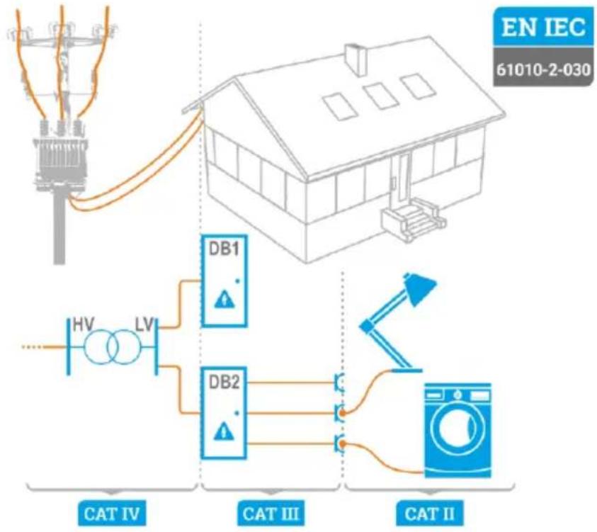
Measurement categories according to EN IEC 61010-2-030:
- CAT II – concerns measurements performed in circuits directly connected to low voltage installations,
- CAT III – concerns measurements performed in buildings installations,
- CAT IV – concerns measurements performed at the source of low voltage installation.
flowchart
graph TD
    A["Utility Pole"] --> B["House"]
    B --> C["DB1"]
    B --> D["DB2"]
    C --> E["Light Bulb"]
    D --> F["Light Bulb"]
    G["Power Supply"] --> H["HV"]
    G --> I["LV"]
    J["Electricity Generator"] --> K["CAT IV"]
    J --> L["CAT III"]
    M["Water Heater"] --> N["CAT II"]
1.2 Behaviour of signalling LEDs

The LED is on continuously

The LED flashes slowly

The LED flashes rapidly
1.3 Safety
In order to provide conditions for correct operation and the correctness of the obtained results, the following recommendations must be observed:
- Before you proceed to operate the system, acquaint yourself thoroughly with the present manual and observe the safety regulations and specifications provided by the producer.
- Any application that differs from those specified in the present manual may result in a damage to the system and constitute a source of danger for the user.
- The LKZ-2500 system must be operated only by appropriately qualified personnel with relevant certificates authorising the personnel to perform works on electric systems. Unauthorized use of the system may result in its damage and may be a source of serious hazard to the user.
- Before connecting the system to power cables, they must be discharged.
- Using this manual does not exclude the need to comply with occupational health and safety regulations and with other relevant fire regulations required during the performance of a particular type of work. Before starting the work with the system in special environments, e.g. potentially fire-risk/explosive environment, it is necessary to consult it with the person responsible for health and safety.
- It is unacceptable to operate the device when:
⇒ it is damaged and completely or partially out of order,
its cords and cables have damaged insulation,
it has been stored for an excessive period of time in disadvantageous conditions (e.g. excessive humidity). If the device has been transferred from a cool to a warm environment with a high level of relative humidity, do not start measurements until the device is warmed up to the ambient temperature (approximately 30 minutes).
- Do not leave unconnected conductor, while the other is connected to the tested network.
- Do not leave unattended device connected to the tested circuit.
- Do not operate the transmitter with open or incorrectly closed battery compartment and do not power it from other sources than those specified in this manual.
• Repairs may be performed only by an authorised service point.
WARNING
Disconnecting the protective conductor is a life hazard for the staff tracing the wires and also for bystanders. Wherever possible you must first disconnect the supply voltage and the phase cable(s). Be particularly careful when removing the protective conductor or the grounding of neutral wire from the system, which must be energized. Ensure that there are no bystanders in the danger area. When the tracing is completed, the connection of the protective conductor or grounding of the neutral conductor MUST be reconnected.

NOTE!
The LKN-2500 transmitter is not intended for direct operation under voltage.

Due to continuous development of the device, its features described in this manual may differ from the actual state.
2 Quick start
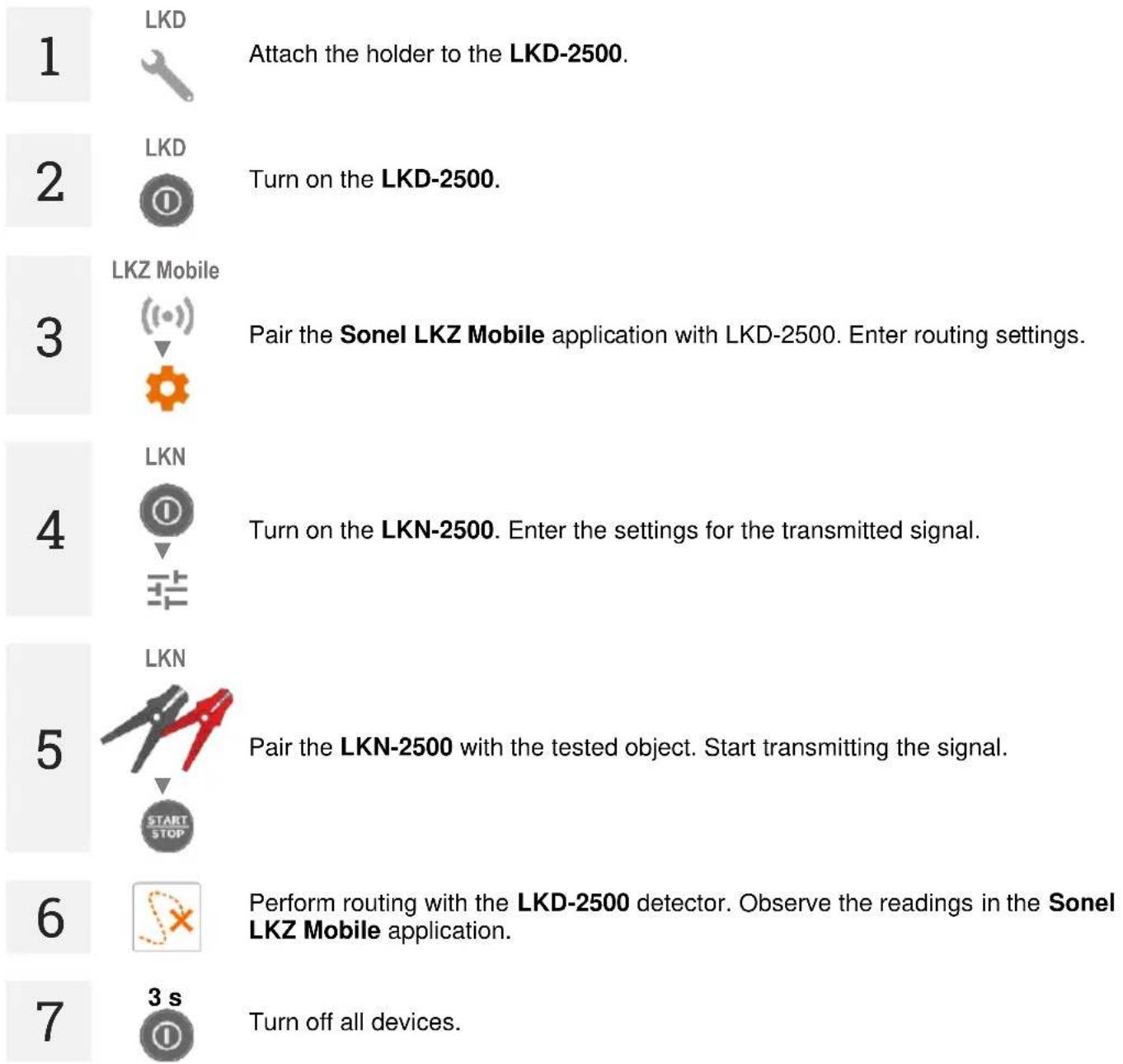
3 Description of the system
3.1 Main features of the system
- Working with energized or non-energized objects.
• Work in passive and active mode.
• 3 methods of active work.
• Detection of cables and infrastructure in the ground. - Cable and infrastructure routing.
- Recording the route of the routed object.
- Sharing route files with other users of the Sonel LKZ Mobile application.
3.2 Principle of system operation
LKZ-2500 is a system consisting of:
• LKN-2500 transmitter,
- LKD-2500 detector,
- Sonel LKZ Mobile application,
- other necessary accessories.
LKN-2500 transmitter injects a locating signal into an underground object. LKD-2500 detector placed along the object traces this signal along the object. The information about position of the traced object is displayed on the Sonel LKZ Mobile app which is connected with the detector. Determination of the object's route is possible based on observation of compass readings and the level of the detected signal.
The system has the ability to trace cables and record routes via the mobile application. Such files can be exported and shared with other users – including those who do not have the LKN-2500 / LKD-2500 device.
The system is capable of operating in passive mode (without the use of the LKN-2500 transmitter) and active mode (with the use of the LKN-2500 transmitter). The active mode allows to introduce the signal in three different methods:
- galvanic – injects tracing signal into the object directly, through crocodile clips and test leads,
- clamp – injects tracing signal into the object through an inductive clamp,
- inductive – injects tracing signal into the object inductively, using the instrument's internal antenna.
3.3 Transmitter LKN-2500
3.3.1 Buttons on the housing
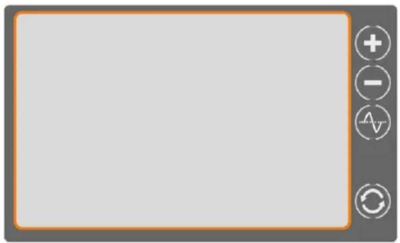
natural_image
Blank gray rectangular frame with orange border and four circular icons on the right side (no text or symbols)
flowchart
graph LR
    A["①"] --> B["Battery"]
    B --> C["A/V/W"]
    C --> D["START/STOP"]

- Turn on the device (press briefly)
• Turn off the device (press and hold)

Method of displaying parameters of the transmitted signal: amperes / volts / watts / resistance

Start/stop signal transmission

Increase the signal strength

Decrease the signal strength

Select the signal frequency

Set the method of connecting the transmitter to the routed object
3.3.2 Display
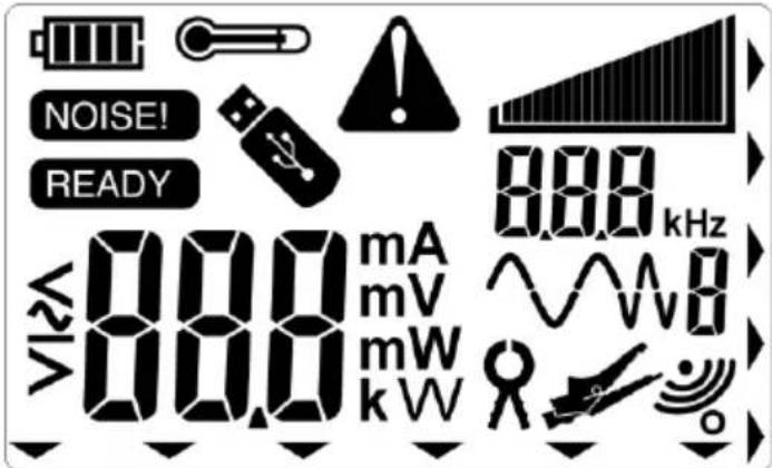

Charging the battery
NOISE!
Interference detected in the connected object
READY
The device is ready to transmit a signal
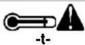
Warning: the meter temperature is higher than permissible

USB memory connected to the instrument

Error/warning/information
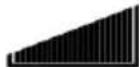
Strength of the transmitted signal.
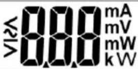
Strength of the transmitted signal.
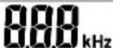
The frequency of the transmitted signal
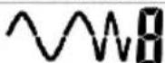
Shape of the transmitted signal.

Inputting a signal into an object: clamp method

Inputting a signal into an object: galvanic method

Inputting a signal into an object: induction method

Indicates a button on the instrument housing
3.3.3 Time settings for automatic shutdown (auto-off)
1

Press and hold down button to turn on the meter. Release only when the settings screen appears.
2

Enter the time after which the device will automatically turn off.
3

Confirm the settings with the START/STOP button.
3.4 LKD-2500 Detector
3.4.1 Buttons on the housing
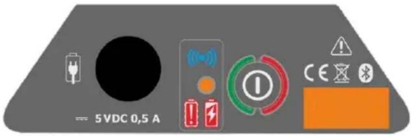

• Turn on the device (press and hold)
• Turn off the device (press and hold)
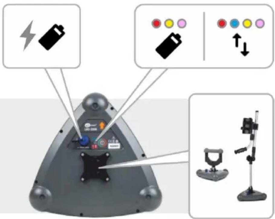
3.4.2 Handles
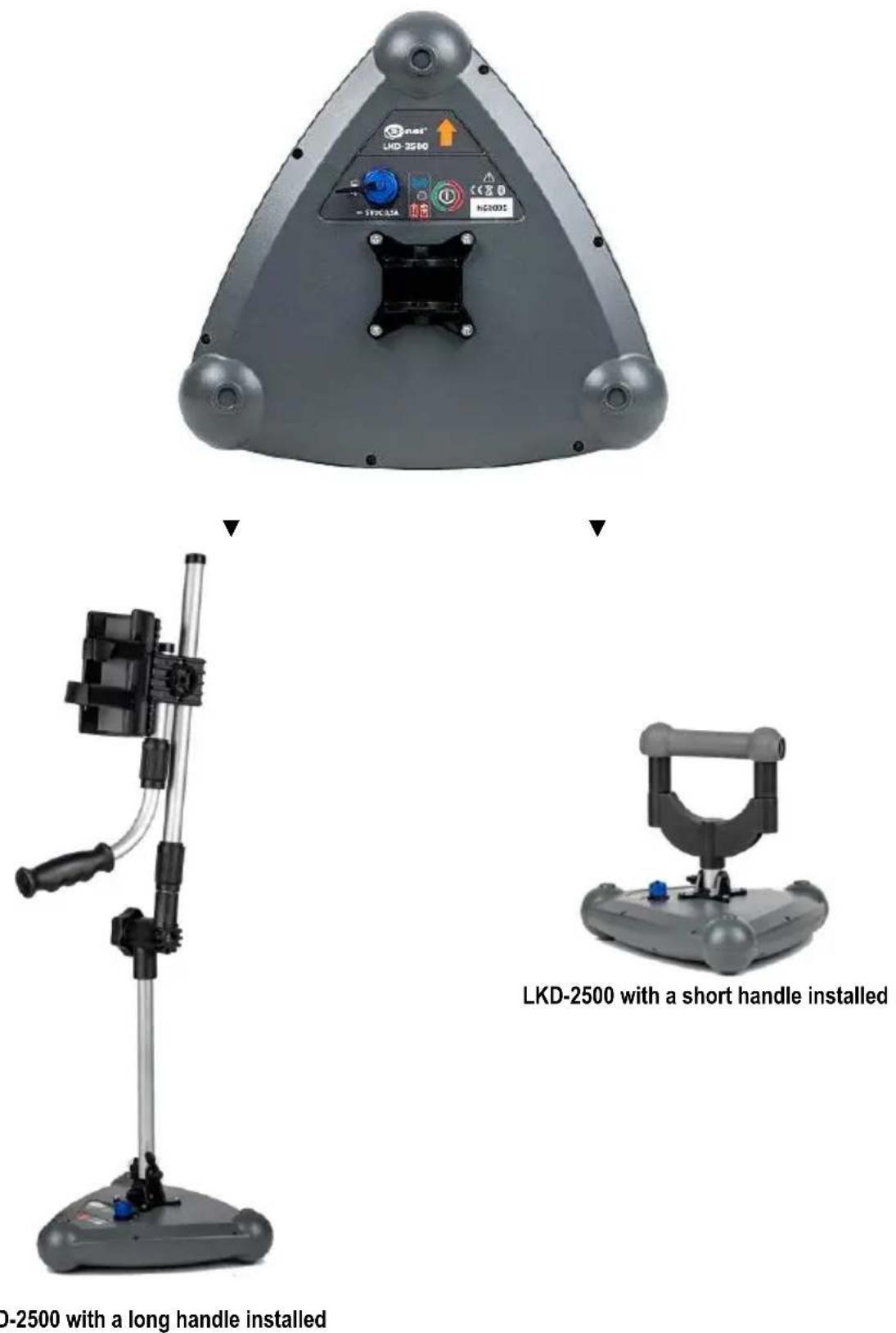
3.5 Sonel LKZ Mobile application
The application works with Sonel LKD-2500 detector. It enables tracing of objects, recording of routes in the memory of the mobile device along with GPS positions of waypoints and additional readings.
The application additionally enables:
• live positioning preview,
• measuring the distance to a specific waypoint,
- export of routes to other mobile devices,
- reading routes from the mobile device's memory,
- preview of all recorded parameters,
- merging routes,
- adding notes to routes and measurement points.
3.5.1 Gestures

Drag your finger across the touchscreen

Touch an item on the touch screen
3.5.2 Menu icons
Expand your mobile device's settings menu
gauge
| Parameter | Value | | --------- | ----- | | h | 0,75 | | d | 0,10 | | a | 8° | | Current | 50 mA | | Frequency | Hz |General

Go to the previous window

Go to the next window

Expand the item

Collapse the item

Return to the main menu

Close window / cancel the action

Save

Refresh

Information
| Menu | ||
| < | Left/expand | > Right/expand |
| Status menu | ||
| 55 | Battery charge level in LKD-2500 | |
Checkpoint menu


Memory
| Add an object |
| Add a folder |
| Add a routed object |
 | Search |
| Go to the parent folder |
Function panel

Save the waypoint to the mobile application memory
Detector operating mode





Frequency of the searched signal (different signals available depending on the operating mode)
Method of signal reception



3.5.3 Measurements

The icon is displayed when the application is paired with the LKD-2500 detector. It takes user to the routing screen.
3.5.4 Bluetooth

Displays a list of available LKD-2500 detectors.
3.5.5 Settings

Here you can configure the app to your needs.
3.5.5.1 Information

Here you can check information about the app.
3.5.5.2 App settings

Available settings:
- ID auto increment – creating new objects in the parent folder with a unique route ID within the existing numbering.
- Name auto increment – creating new names for memory elements according to previously entered names and types.
- Imperial distance unit – setting distance units.
- Detector sound – here you can turn on / off system sounds.
• Signal chart – here you can turn on / off RSSI characteristics.
3.5.6 Creating a memory structure
1

Select icon Folders.
2

Add a folder.
3

Enter the object details.
4

Save Changes.
5
Enter the created folder and:

add a lower-level folder (and enter its data),

add the routed object (and enter its data).
4 Pairing devices
1
LKD

Turn on LKD-2500 detector.
2

Turn on Sonel LKZ Mobile application.
3

Select the Bluetooth icon.
4

Connect to the LKD-2500 detector.
5

Close the pairing window.

When communication between the LKD-2500 and the Sonel LKZ Mobile application is lost and not restored within 5 minutes, the LKD-2500 will automatically turn off.

Additional information displayed by the device
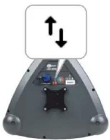
natural_image
Top-down view of a remote control device with two directional arrows indicating movement (no text or symbols)LKD without bat- tery charging
LKD in battery charging mode







LKD switched off
LKD switched on
Synchronization with the Sonel LKZ Mobile application is in progress.
Connection to the Sonel LKZ Mobile application established.
5 Routing
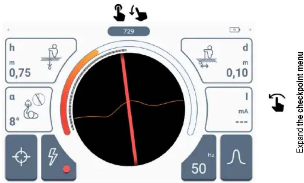
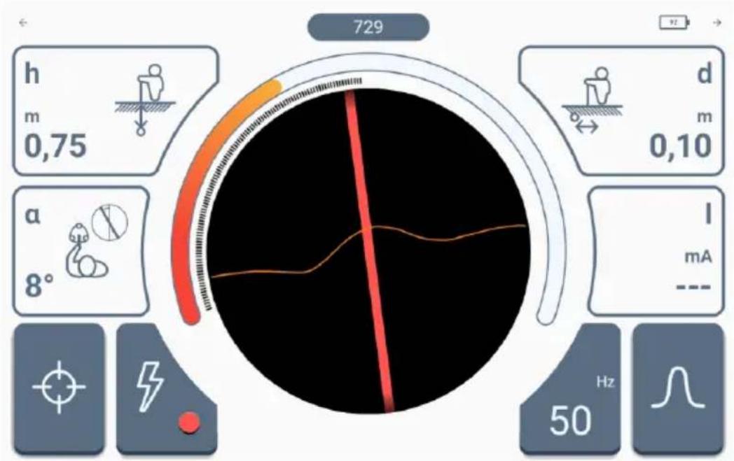
5.1 Routing screen of the Sonel LKZ Mobile application
Routing screen of the Sonel LKZ Mobile application is shown below.
gauge
| Parameter | Value | | --------- | ----- | | h | 0.75 | | d | 0.10 | | a | 8° | | l | mA | | Hz | 50 |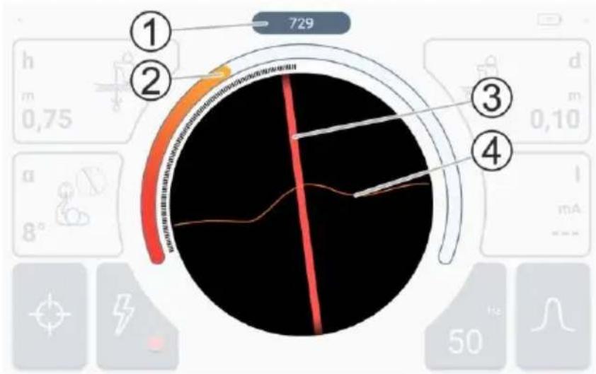
In the central part there is a compass with a route preview.
1 - received signal strength.
2 - graph of the received signal strength.
3 - course of the routed object relative to the detector axis.
4 - RSSI characteristics.

- The area presented on the compass corresponds to the area around the LKD-2500 detector with a diameter of 2 meters.
- When the signal is strong enough, an arrow pointing towards it is displayed to direct the user to it.
-
When line 3 turns grey, it means that the algorithm assesses that the signal does not meet the correctness conditions, which means that:
-
the displayed line is an approximation of the position of the traced object (the indications are stable) or
- the detector has detected interference (indications are unstable).
gauge
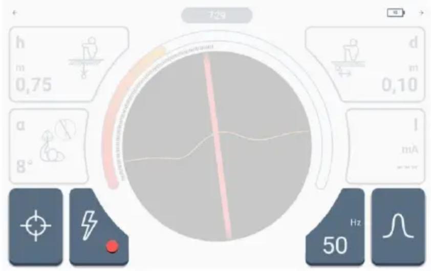
| Parameter | Value | |---|---| | h | 0,75 | | m | 0,10 | | d | 0,10 | | m | 0,75 | | a | 8° | | I | mA | | Hz | 50 |In the upper and lower parts there are controls and settings icons described in sec. 3.5.2.
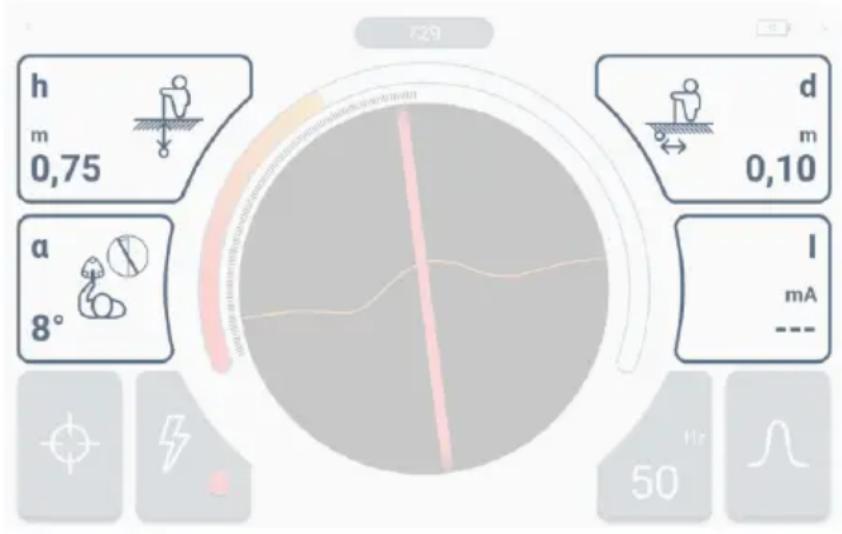
There is a set of indications on the sides.
h - depth of the routed object relative to the detector, expressed in meters.
α – angle of deviation of the routed object relative to the detector axis, expressed in degrees.
d - distance of the routed object from the detector, expressed in meters.
There is an additional reading field in the lower right corner.
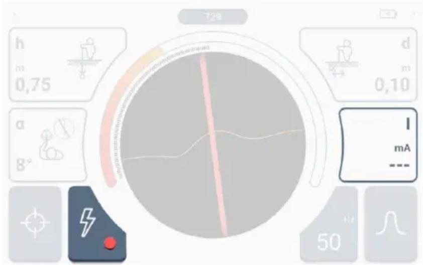
The indications of this field depend on the active routing mode.
- Power mode – dashes are displayed (no reading).
- Radio mode – the currently detected leading frequency of the signal flowing through the routed object is displayed.
- Signal mode – the signal current flowing through the routed object is displayed.
5.2 Methods of signal reception
The LKZ-2500 system can receive the signal in three different ways.
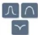
Narrow. This characteristic is used to precisely determine the location of the signal and for accurate routing. When it is active, an algorithm determines whether the conditions for the correctness of the tracked signal are met

- If the algorithm conditions are met, the line on the radar is coloured according to the set routing mode.
- If the algorithm conditions are not met, the received signals are still presented, but as a grey line.
Wide. This characteristic is used to find the signal and to map the area. When it is active, an algorithm determines whether the conditions for the correctness of the tracked signal are met.

- If the algorithm conditions are met, the line on the radar is coloured according to the set routing mode.
- If the algorithm conditions are not met, the received signals are still presented, but as a grey line.
Selective. This characteristic is used to identify received signals and to route very low strength signals (the intensity of the audio signal decreases). When it is active, the radar displays only signals that meet the criteria of the algorithm, which determines the fulfilment of the correctness of the tracked signal.

5.3 Routing modes
5.3.1 Operation in passive mode - Power
Operation in the Power passive mode involves locating of objects carrying own signals with a power frequency of 50 Hz or 60 Hz. This means that such routing can only take place over active powered facilities. In this mode, using the LKN-2500 transmitter to force a signal in the object is not necessary. This results in faster preparation for location and routing and no need to disconnect the facility from power supply or interfere with its structure.
1

Select Power mode.
2

Select the frequency of the signal searched in the routed object.
3
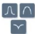
Select the method of signal reception.
4 Place the LKD-2500 detector over the object to be traced.
- When you start getting closer to the object, you will notice an increase in the strength of the received signal on the bargraph and numerical indicator.
- When you are directly above an object or in its immediate vicinity, you will see a line on the screen showing its course.
5 Now you just need to follow its route according to the indications.
6 If necessary, change the way of receiving the signal.
5.3.2 Operation in passive mode – Radio
Operation in the Radio passive mode involves locating of objects carrying own signals or signals induced at frequencies from 2.5 kHz to 52 kHz. This means that such routing can take place over all active or inactive objects that carry signals with a frequency within the measurement range. In this mode, using the LKN-2500 transmitter to force a signal in the object is not necessary. This results in faster preparation for location and routing and enables the location of various types of infrastructure, not necessarily electricity - also telecommunications or simply conductive.
1 Select Radio mode.
2 Select the frequency of the signal searched in the routed object.
3 Select the method of signal reception.
4 Place the LKD-2500 detector over the object to be traced.
- When you start getting closer to the object, you will notice an increase in the strength of the received signal on the bargraph and numerical indicator.
- When you are directly above an object or in its immediate vicinity, you will see a line on the screen showing its course.
5 Follow the route of the object as indicated.
6 If necessary, change the way of receiving the signal.
5.3.3 Working in active mode – Signal
Working in the Signalactive mode involves precise locating of objects capable of transmitting signals. This means that such routing can take place over all active or inactive objects capable of carrying signals. In this mode using the LKN-2500 transmitter to force a signal in the object is necessary.
5.3.3.1 Methods of introducing a signal to the routed object
- Galvanic method – involves introducing a signal into the object galvanically, i.e. via wires. The wires are connected to the transmitter, the ground electrode and the object being routed. The galvanic method ensures the best introduction of the generated signal to the object and, consequently, the most effective location and routing.

• The routed object must be out inactive, i.e. de-energized.
- To improve the strength of the transmitted signal, ground the end of the routed object.
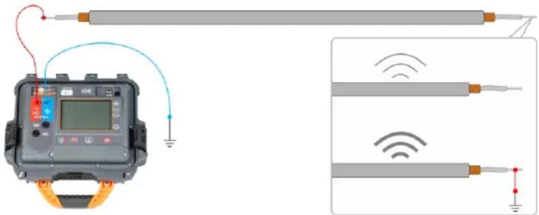
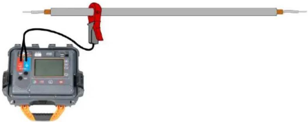
- Clamp method – involves introducing a signal to the object inductively using clamps. The clamps are connected to the transmitter and attached to the routed object.
natural_image
Electrical testing setup with a digital display and clamp, no visible text or symbols
The tested object can be live.
- Inductive method – involves introducing a signal to the object inductively using internal antenna of the transmitter. The device is placed over the object as directed by the arrow on the housing. The signal is induced in all objects located under the transmitter, so it will be possible to locate more objects located underground. The strength of the signal generated in the object depends in this case on the depth at which the object is located, as well as on the type of ground and the presence of other conductive infrastructure.
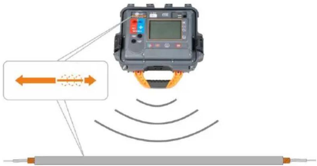

The tested object can be live.
5.3.3.2 Introducing signal
| 1 | © | In the LKN-2500 set the method of introducing the signal (galvanic / clamp / inductive) to the routed object. |
| 2 | Connect the signal forcing circuit. | |
| 3 | Select the shape and the frequency of the transmitted signal | |
| 4 | Set the signal strength.In the induction method, the signal strength is locked at the maximum level. | |
| 5 | START STOP | Press START/STOP to start transmitting the signal. |
| 6 | AVW | When necessary, change the method of displaying parameters of the transmitted signal: amperes / volts / watts / resistance |

Additional information displayed by the device




5.3.3.3 Routing
1

In Sonel LKZ Mobile app, select Signal operating mode.
2

Select the frequency of the signal that the LKN-2500 introduces to the router object.
3
Select the method of signal reception.
4
Place the LKD-2500 detector over the object to be traced.
- When you start getting closer to the object, you will notice an increase in the strength of the received signal on the bargraph and numerical indicator.
- When you are directly above an object or in its immediate vicinity, you will see a line on the screen showing its course.
5

Follow the route of the object as indicated.
6
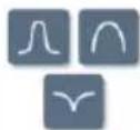
If necessary, change the way of receiving the signal.
5.4 Route registration
1

Pair the Sonel LKZ Mobile application with LKD-2500 detector.
2

In the main menu, select Measurements.
3

Select operation mode.
4

Select the frequency of the signal that the LKN-2500 introduces to the routed object.
5

Follow the route of the object as indicated.

This icon will save the GPS location of the route point along with all its data to the application memory.
After expanding the checkpoint menu, a list of saved points will appear.
If necessary, select a checkpoint. It will expand to the form below.
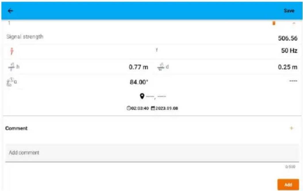
1 - checkpoint number in the series
/ (p) / - detector operating mode: Power / Radio / Signal.
h – depth of the routed object relative to the detector, expressed in meters.
α - angle of deviation of the routed object relative to the detector axis, expressed in degrees.
d - distance of the routed object from the detector, expressed in meters.
f - frequency:
⇒ frequency of the signal sought (only in Signal mode),
leading frequency of the signal sought (only in Radio mode),
I – signal current flowing through the routed object, expressed in milliamps (only in Signal mode).

- GPS location of the checkpoint

– time of saving the checkpoint

– date of saving the checkpoint
Add comment – field for adding a comment
Use icon to
Finally, expand the checkpoint menu and save the results to an object in the app memory – the Save command in the top bar.
5.5 Restoring the route
1

In the main menu, select Folders.
2

Go to the routed object. A map will appear with a route marked by the save checkpoints.
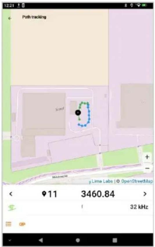
1 – checkpoint number in the series
/ (1) / - detector operating mode: Power / Radio / Signal.
f – frequency of the signal sought (only in Signal mode).
- the icon expands the list of all saved route points.
- adding a note.
Swipe up from the bottom of the values area to view the signal parameters at the control point.
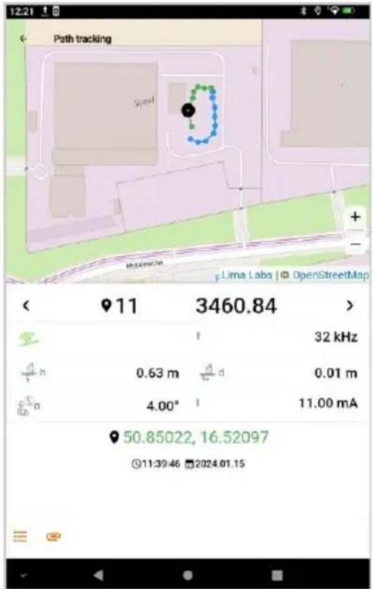
h – depth of the routed object relative to the detector, expressed in meters.
α - angle of deviation of the routed object relative to the detector axis, expressed in degrees.
d – distance of the routed object from the LKD detector, expressed in meters.
f - frequency:
⇒ frequency of the signal sought (only in Signal mode),
⇒ leading frequency of the signal sought (only in Radio mode),
I – signal current flowing through the routed object, expressed in milliamps (only in Signal mode).

– GPS location of the checkpoint.

– time of saving the checkpoint.

– date of saving the checkpoint.

In order for the map of the route area to be loaded, the mobile device must have Internet access.
6 Software update
6.1 LKN-2500 transmitter
1 Download the update file from the manufacturer's website.
2 Save the update file to a USB stick. The memory must have the FAT32 file system.
3 Turn on the LKN-2500.
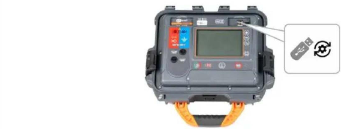
4 Insert the USB stick into the USB port of the LKN-2500. The installed and latest available software version will be displayed on the screen.
natural_image
Close-up of a digital testing device with control panel and orange strap, no visible text or symbols on the device itself.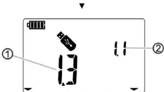
1 - software version on the USB memory stick
2 - software version installed in the device
5

If the version on the USB stick is higher than the installed version, press START/STOP to update.
6
After a successful update, the instrument will return to the transmitting screen.
6.2 LKD-2500 Detector
1 Download the update file from the manufacturer's website to the mobile device.
2 Turn on Sonel LKZ Mobile application.
3 Turn on the LKD-2500.
4 Using the mobile application, pair it with the device.
5

flowchart
graph TD
    A["Gear"] --> B["Clock Icon"]
    B --> C["↑"]
    C --> D["Gear Icon"]
Go to Settings ▶ Update and select the update file. A message verifying the correctness of the file will be displayed on the screen. Then confirm the update.
6
A progress bar will appear on the screen. After successful update, the application will display the main menu.
7 Troubleshooting
Before sending the instrument for repairs, contact our service department. It may be possible that the meter is not damaged, and the problem has been caused by some other reasons.
The meter can only be repaired at outlets authorized by the manufacturer.
Troubleshooting of typical problems during the use of the instrument is described in the table below.
7.1 LKN-2500 transmitter
7.1.1 Error codes
| Error code | Cause | Action | |
 | Voltage present on tested object ≥50 V. | Disconnect the voltage from the object. | |
 | Too high or too low supply voltage to the galvanic actuator – damaged internal power module. | ||
 | Reference voltage error. | Contact the customer service centre and provide the error code to get help. | |
 | Relay switching error. | ||
 | Relay switching error. | ||
 | Relay switching error. | ||
 | Relay switching error. | ||
 | Calibration coefficients checksum error. | ||
 | Galvanic transmitter on/off error. | ||
 | Inductive transmitter on/off error. | ||
 | Relay switching error. | ||
 | Relay switching error. | ||
 | Relay switching error. | ||
 | Relay switching error. | ||
 | Charging error. Charging cancelled. | Contact the customer service centre and provide the error code to get help. | |
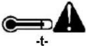 | The temperature of the device is higher than permissible. | Turn off the device, wait 10 minutes, turn the device on and check if the error persists. If yes, contact the customer service centre and provide the error code to get help. | |
 | Blown fuse. | Replace the fuse. | |
 | The device was previously turned off because the Auto OFF time elapsed. | Turn the meter off and on. | |
 | The previous shutdown of the device occurred from battery discharge. | Charge the battery | |
7.1.2 Fuse replacement
The device is protected by two fast-acting fuses 5 x 20 mm 0.5 A / 250 V AC. To replace the fuse, unscrew the socket head, place a working fuse in place of the damaged fuse, and then screw on the socket head.
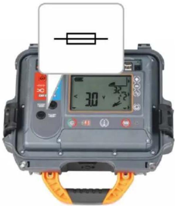

NOTE!
Do not use fuses other than those listed in this manual.
8 Power supply

NOTE!
Before operating the meter, discharge the battery and then fully charge it, so that the indication of its charged status is correct.
8.1 Battery power
The meter is powered by a lithium-ion battery. The meter is charged by a USB power supply. It can be also charged from the car 12V accessory socket, using an optional converter.
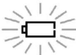
The charge level of the rechargeable battery is indicated by the symbol in the display on a permanent basis
8.1.1 LKN-2500 transmitter
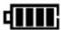
Battery charge <100%.
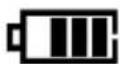
Battery charge ≤87%.
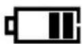
Battery charge ≤62%.
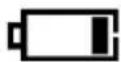
Battery charge ≤37%.
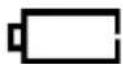
Battery charge ≤12%.
natural_image
Simple line drawing of a battery with radiating lines (no text or symbols)Battery charge ≤5%.

Additional information displayed by the device

The device was previously turned off because the Auto OFF time elapsed.

The previous shutdown of the device occurred from battery discharge.
8.1.2 LKD-2500 Detector
The battery charge level of the device is indicated in the Sonel LKZ Mobile application.
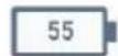
Battery charge in %.

When communication between the LKD-2500 and the Sonel LKZ Mobile application is lost and not restored within 5 minutes, the LKD-2500 will automatically turn off.
8.2 Charging rechargeable battery
8.2.1 LKN-2500 transmitter

NOTE!
- While the device is charging, do not turn it on or off. This may damage it. It is only allowed to charge the device when it is turned on or off.
- Do not power the device from sources other than those listed in this manual.
Charging starts once the power supply has been connected to the device, regardless of the fact whether the device is on or off. The charging status is indicated by active LED.
Charging with:
- a charger,
- the car cigarette lighter socket, using an optional converter.
Indication of completed charging:

Additional information displayed by the device

Charging error. Charging cancelled.
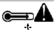
The temperature of the device is higher than permissible.
8.2.2 LKD-2500 detector

NOTE!
Do not power the device from sources other than those listed in this manual.
Charging starts once the power supply has been connected to the device, regardless of the fact whether the device is on or off and whether it operates or not. The charging status is indicated by active LED.
Charging with:
- a charger
- power bank,
- the car cigarette lighter socket, using an optional converter.
- computer USB port,
• via the USB-A / USB-C adapter.
When the device is turned off by button, the charging process is not stopped.
Signalling of completed charging: (signalling in the Sonel LKZ Mobile application).
8.3 Power supply from mains
It is possible to charge the battery of LKD-2500 when carrying out the measurements. To do this, simply connect the power supply to the device.
8.4 General rules for using Li-Ion rechargeable batteries
- Store the meter with batteries charged at least to 50%. The battery pack may be damaged if stored when fully discharged. The ambient temperature for prolonged storage should be maintained within the range of 5^ C... 25^ C. The environment should be dry and well ventilated. Protect the device from direct sunlight.
- Charge the batteries in a cool, well-ventilated place at a temperature of 10^ C ... 28^ C. Modern fast chargers detect both too low and too high temperature of rechargeable batteries and react to the situation adequately. When the temperature is too low, charging is prevented as it may irreparably damage the batteries.
- Do not charge or use the batteries in extreme temperatures. Extreme temperatures reduce the lifetime of rechargeable batteries. Always observe the rated operating temperature. Do not dispose of the battery pack into fire.
- Li-lon cells are sensitive to mechanical damage. This kind of damage may cause its permanent damage and thus cause ignition or explosion. Any interference in the structure of Li-lon battery pack may cause its damage. This may result in its ignition or explosion. A short-circuit of the battery poles "+" and "-" may permanently damage the battery pack or even cause its fire or explosion.
- Do not immerse Li-Ion battery in liquids and do not store in humid conditions.
- If the electrolyte contained in the Lithium-Ion battery pack comes into contact with eyes or skin, immediately rinse the affected area with plenty of water and consult with a doctor. Protect the battery against unauthorised persons and children.
- When you notice any changes in the Lithium-Ion battery pack (e.g. changes in colour, swelling, excessive temperature), stop using the battery pack. Li-Ion batteries that are mechanically damaged, overcharged or excessively discharged are not suitable for use.
- Any misuse of the battery may cause its permanent damage. This may result in its ignition. The seller and the manufacturer shall not be liable for any damages resulting from improper handling of the Li-Ion battery pack.
9 Status signalling
9.1 LKN-2500 transmitter
natural_image
Close-up of a digital testing device with a display and orange grip, no visible text or symbols
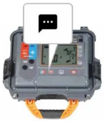
LKN-2500 turned off.

LKN-2500 turned off, battery is charging.

LKN-2500 turned on, the charger disconnected.

LKN-2500 turned on, battery is charging.
9.2 LKD-2500 Detector
natural_image
Top-down view of a gray electronic device with a speech bubble icon above it, no visible text or symbols on the device itself.
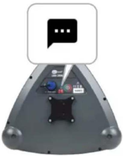
LKD-2500 turned off, the charger disconnected.

LKD-2500 turned off, battery is charging.

LKD-2500 turned on, the charger disconnected.

LKD-2500 turned on, the charger disconnected. (Synchronization with the Sonel LKZ Mobile application is in progress.)

LKD-2500 turned on, battery is charging. (Synchronization with the Sonel LKZ Mobile application is in progress.)

LKD turned on, the charger disconnected, connection to the Sonel LKZ Mobile application established.

LKD turned on, battery is charging, connection to the Sonel LKZ Mobile application established.
10 Cleaning and maintenance

NOTE!
Use only the maintenance methods specified by the manufacturer in this manual.
The casing of the device may be cleaned with a soft, damp cloth using all-purpose detergents. Do not use any solvents or cleaning agents which might damage the casing (powders, pastes, etc.).
Clean the probe with water and dry it.
The test leads should be cleaned with water and detergents, and then dried.
The electronic system of the meter does not require maintenance.
11 Storage
In the case of storage of the device, the following recommendations must be observed:
- disconnect all the test leads from the meter,
- clean the meter and all its accessories thoroughly,
- wind the test leads.
12 Dismantling and utilisation
Worn-out electric and electronic equipment should be gathered selectively, i.e. it must not be placed with waste of another kind.
Worn-out electronic equipment should be sent to a collection point in accordance with the regulations valid in a given region.
Before the equipment is sent to a collection point, do not dismantle any elements.
Observe local regulations concerning disposal of packages, waste batteries and rechargeable batteries.
13 Technical data
13.1 LKN-2500 transmitter
The device does not have the character of a standard and therefore is not subject to calibration. The proper form of control for this type of instrument is checking.
Features
• Voltage measurement
- Resistance measurement
• Power measurement
- Current measurement
- The ability to work with live cables (clamp and inductive method)
- Battery level indication
Operating data
a) type of insulation acc. to EN 61010-1 and EN IEC 61557..... double
b) measurement category acc. to EN 61010-1 CAT II 300 V
c) ingress protection acc. to EN 60529
- with open housing IP40
- with closed housing IP67
d) power supply
- rechargeable battery ....Li-Ion 7.2 V 9.8 Ah
- operating time when powered by a battery .... max. 16 h
- charging temperature ....0°C...45°C
e) dimensions 318 x 257 x 152 mm
f) weight 3.4 kg
g) operating temperature....-10..+50°C
h) storage temperature....-20..+60°C
i) reference temperature....+23 ± 2°C
j) altitude a.s.l. ≤2000 m
k) auto-off function 0.5 h..9.5 h
I) quality standard....development, design and manufacturing are ISO 9001 compliant
m) the product meets EMC requirements (immunity for industrial environment) according to the following standards.... EN 61326-1, EN 61326-2-2
13.2 LKD-2500 detector
The device does not have the character of a standard and therefore is not subject to calibration. The proper form of control for this type of instrument is checking.
Features
• 4-stage signal filtering
• Signal detection at the indicated azimuth
- Offset measurement (the compass covers area of 2-metre diameter around the LKD-2500)
• Measurement of angle of deviation of the routed object relative to the detector axis
• Measurement of the signal current flowing through the routed object
- Battery level indication
- With Sonel LKZ Mobile – indication of the currently detected signal leading frequency
- With Sonel LKZ Mobile – acoustic and visual detection indication (360° line direction indicator)
- With Sonel LKZ Mobile – RSSI characteristics
- With Sonel LKZ Mobile – indication of the received signal strength (bar graph and numerical value)
- With Sonel LKZ Mobile – metric or imperial units
Depth measurement accuracy
⇒ The abbreviation "m.v." used in the specification of accuracy denotes a measured value
| Depth\Mode | Power | Radio | Signal (8 kHz) | Signal (32 kHz) |
| ≤1 m | 10% m.v. | 10% m.v. | 5% m.v. | 2.5% m.v. |
| ≤4 m | 10% m.v. | 10% m.v. | ||
| ≤6 m | unspecified | |||
- The depth of the cable should be measured parallel to and directly above the cable route.
• Accuracy is correlated with the current that can be forced in the object (defined reference conditions).
Operating data
a) type of insulation acc. to EN 60529....IP65
b) power supply
a) type of insulation acc. to EN 60529....IP65 b) power supply
- rechargeable battery.... Li-Ion 3.6 V 6.7 Ah
- operating time when powered by a battery .... max. 13 h
- charging interface ....USB-C 5 V / 3 A
- charging time ....max 4 hours
- charging temperature ....+10°C...45°C
a) dimensions 290 x 275 x 100 mm
b) weight 1,2 kg
c) operating temperature....-10°C...+50°C
d) storage temperature....-20°C...+60°C
e) reference temperature....+23°C±2°C
f) operating humidity....20%..90%
g) reference humidity 40%..60%
h) data transmission
- wireless communication standard ....Bluetooth 5.0 BLE
- communication range .... up to 50 m in open space
i) Auto-Off when communication between the LKD-2500 and the Sonel LKZ Mobile application is lost 5 min
j) altitude a.s.l. ≤2000 m
k) quality standard....development, design and manufacturing are ISO 9001 compliant
I) the product meets EMC requirements (immunity for industrial environment) according to the following standards ....
EN 61326-1, EN 61326-2-2
14 Manufacturer
The manufacturer of the device and provider of guarantee and post-guarantee service:
SONEL S.A.
Wokulskiego 11
58-100 Šwidnica
Poland
tel. +48 74 884 10 53 (Customer Service)
e-mail: customerservice@sonel.com
web page: www.sonel.com

NOTE!
Service repairs must be performed only by the manufacturer.
NOTES
NOTES
NOTES
SONEL S.A.
Wokulskiego 11
58-100 Świdnica
Poland
Customer Service
tel. +48 74 884 10 53
e-mail: customerservice@sonel.com
www.sonel.com
- USER MANUAL
- CABLES AND UNDERGROUND INFRASTRUCTURE LOCATOR
- LKN-2500
- LKD-2500
- CONTENTS
- General information....5
- Quick start 7
- Description of the system....8
- Pairing devices....17
- Routing 18
- Software update....30
- Troubleshooting....32
- Power supply....34
- Status signalling 37
- Cleaning and maintenance 38
- Storage....38
- Dismantling and utilisation....38
- Technical data....39
- Manufacturer 41
- General information
- Safety symbols
- Behaviour of signalling LEDs
- Safety
- WARNING
- NOTE!
- Quick start
- Description of the system
- Main features of the system
- Principle of system operation
- Transmitter LKN-2500
- Buttons on the housing
- Display
- Time settings for automatic shutdown (auto-off)
- LKD-2500 Detector
- Buttons on the housing
- Handles
- Sonel LKZ Mobile application
- Gestures
- Menu icons
- General
- Measurements
- Bluetooth
- Settings
- Information
- App settings
- Creating a memory structure
- Pairing devices
- Additional information displayed by the device
- Routing
- Routing screen of the Sonel LKZ Mobile application
- Methods of signal reception
- Routing modes
- Operation in passive mode - Power
- Operation in passive mode – Radio
- Working in active mode – Signal
- Methods of introducing a signal to the routed object
- Introducing signal
- Routing
- Route registration
- Restoring the route
- Software update
- LKN-2500 transmitter
- LKD-2500 Detector
- Troubleshooting
- LKN-2500 transmitter
- Error codes
- Fuse replacement
- Power supply
- Battery power
- LKN-2500 transmitter
- LKD-2500 Detector
- Charging rechargeable battery
- LKN-2500 transmitter
- LKD-2500 detector
- Power supply from mains
- General rules for using Li-Ion rechargeable batteries
- Status signalling
- LKN-2500 transmitter
- LKD-2500 Detector
- Cleaning and maintenance
- Storage
- Dismantling and utilisation
- Technical data
- LKN-2500 transmitter
- Features
- Operating data
- LKD-2500 detector
- Depth measurement accuracy
- Manufacturer
Brand : Sonel
Model : LKZ-2500 Start
Category : Detector