MMR-640 - Measurement Sonel - Free user manual and instructions
Find the device manual for free MMR-640 Sonel in PDF.


| Type of product | Low Resistance Meter |
| Brand | Sonel |
| Model | MMR-640 |
| Dimensions (L x W x H) | 318 x 257 x 152 mm |
| Weight | approx. 3.5 kg |
| Power supply | Li-Ion rechargeable battery 7.2 V 8.8 Ah, AC adapter 90 V–265 V 50/60 Hz |
| Battery charging time | approximately 3.5 hours |
| Number of measurements (at 10 A) | 700–800 depending on ambient temperature |
| Display | Graphical TFT, 800 x 480 points, touch screen |
| Measurement ranges (resistance) | 0…1999.9 Ω, 8 ranges (0.1 μΩ resolution at lowest range) |
| Measuring currents | 1 mA, 10 mA, 100 mA, 1 A, 10 A |
| Accuracy (at 10 A) | ±(0.25% m.v. + 2 digits) |
| Measurement mode | Bidirectional (automatic or manual), unidirectional |
| Memory capacity | Internal memory (7.18 GB total, approx. 6.76 GB free) plus USB flash drive support |
| Interface | USB (type B for PC, dual USB A for flash memory) |
| Ingress protection (closed housing) | IP67 |
| Safety category | CAT III 600 V (with leads up to 50 V for long leads) |
| Overvoltage protection | Up to 600 V AC for 10 seconds |
| Operating temperature | -10°C to +50°C |
| Storage temperature | -20°C to +60°C |
| Humidity | 20% to 90% |
| Software update | Via USB flash drive, downloadable from www.sonel.pl |
| Language support | Multiple languages (including EN, DE, ES, PL) |
| Maintenance | Clean with soft damp cloth and mild detergent; no solvents |
Frequently Asked Questions - MMR-640 Sonel
User questions about MMR-640 Sonel
0 question about this device. Answer the ones you know or ask your own.
Ask a new question about this device
Download the instructions for your Measurement in PDF format for free! Find your manual MMR-640 - Sonel and take your electronic device back in hand. On this page are published all the documents necessary for the use of your device. MMR-640 by Sonel.
USER MANUAL MMR-640 Sonel
natural_image
Technical line drawing of a device rear panel with labeled ports and buttons (no text or symbols)USER MANUAL
LOW RESISTANCE METER
MMR-640
MMR-640
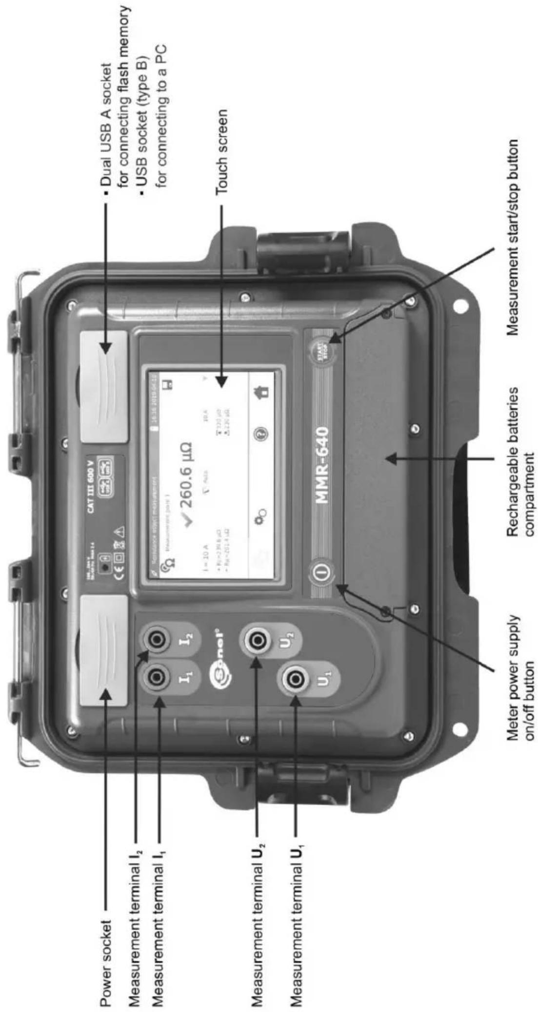
LOW RESISTANCE METER
MMR-640
USER MANUAL

SONEL S.A.
Wokulskiego 11
58-100 Świdnica
Poland
Version 1.07 05.07.2023
Thank you for purchasing our low-resistance meter. MMR-640 is a modern, high-quality measuring device, which is easy and safe to use. Please acquaint yourself with this manual in order to avoid measuring errors and prevent possible problems in operation of the meter.
CONTENTS
1 Safety 5
2 General settings - menu 6
2.1 Meter settings....6
2.1.1 Energy saving....6
2.1.2 Sound settings 7
2.1.3 PIN code settings....8
2.1.4 Display brightness settings....8
2.2 Memory settings....9
2.2.1 Memory management 9
2.2.2 Object types database.... 10
2.2.3 Object names database 11
2.2.4 Resistance limits database....12
2.3 Software update....14
2.4 Service....15
2.5 User interface settings....15
2.5.1 Language selection.... 16
2.5.2 Selecting the startup screen....16
2.5.3 Changing the date and time 17
2.6 Information about the meter 17
2.7 Factory (default) settings....18
2.8 Communication with PC....19
3 Measurements....20
4 Memory 23
4.1 Memory management (clients, objects, measuring points) 23
4.1.1 Entering the clients....23
4.1.2 Entering objects, subobjects, measurement points....24
4.1.2.1 Entering objects and subobjects....24
4.1.2.2 Entering measurement points 27
4.2 Storing the measurement results in the memory....29
4.2.1 Entering the results of measurements with previously organized memory 29
4.2.2 Entering the results of measurements without previously organized memory 30
4.2.2.1 Method 1....30
4.2.2.2 Method 2....32
4.3 Viewing memory data....33
4.4 "Search" in the memory....34
4.5 Copying client data from the memory to USB stick and vice versa 36
4.6 Deleting data....37
4.6.1 Deleting the meter's memory data....37
4.6.2 Deleting a client 37
4.6.3 Deleting an object 38
5 Power supply....39
5.1 Monitoring the power supply voltage....39
5.2 Replacing the battery pack....39
5.3 General rules for using Li-Ion rechargeable batteries ....40
6 Cleaning and maintenance 40
7 Storage....40
8 Dismantling and disposal 41
9 Technical data 41
9.1 Basic data 41
9.2 Other technical data....42
10 Manufacturer 42
1 Safety
MMR-640 is a meter designed for measuring resistance of various types of connections (welded, soldered, butt). It is used to obtain results that determine safety condition of electrical installations. Therefore, in order to provide conditions for correct operation and accuracy of obtained results, the following recommendations must be observed:
- Before you proceed to operate the meter, acquaint yourself thoroughly with the present manual and observe the safety regulations and specifications provided by the producer.
- MMR-640 meter is designed to measure low-resistance values. Any application that differs from those specified in the present manual may result in a damage to the device and constitute a source of danger for the user.
- In case of measurements on systems, components and devices that may be under dangerous voltage, MMR-640 may be used only by qualified persons who are authorized to work on electric installations. Unauthorized use of the meter may result in its damage and may be a source of serious hazard to the user.
- Using this manual does not exclude the need to comply with occupational health and safety regulations and with other relevant fire regulations required during the performance of a particular type of work. Before starting the work in special environments – e.g. potentially fire-risk/explosive environment – it is necessary to consult it with the person responsible for health and safety.
- It is unacceptable to operate the device when:
⇒ a damaged meter which is completely or partially out of order,
⇒ a meter with damaged insulation,
⇒ a meter stored for an excessive period of time in disadvantageous conditions (e.g. excessive humidity). If the meter has been transferred from a cool to a warm environment with a high level of relative humidity, do not start measurements until the meter is warmed up to the ambient temperature (approximately 30 minutes).
• Before measurement make sure that test leads are connected to appropriate measuring terminals.
- Do not operate a meter with an open or incorrectly closed battery compartment and do not power it from other sources than those specified in this manual.
- The inputs of the meter are protected electronically against overload e.g. due to having been connected to a live circuit: for all combinations of inputs - up to 600 V for 10 seconds.
• Repairs may be performed only by an authorised service point.
• The device meets the requirements of EN 61010-1, EN 61010-2-030 and EN 61010-031.

- The manufacturer reserves the right to introduce changes in appearance, equipment and technical data of the meter.
- An attempt to install drivers in 64-bit Windows 8 and Windows 10 may result in displaying "Installation failed" message.
Cause: Windows 8 and Windows 10 by default block drivers without a digital signature. Solution: Disable the driver signature enforcement in Windows.
2 General settings - menu
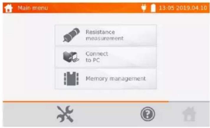
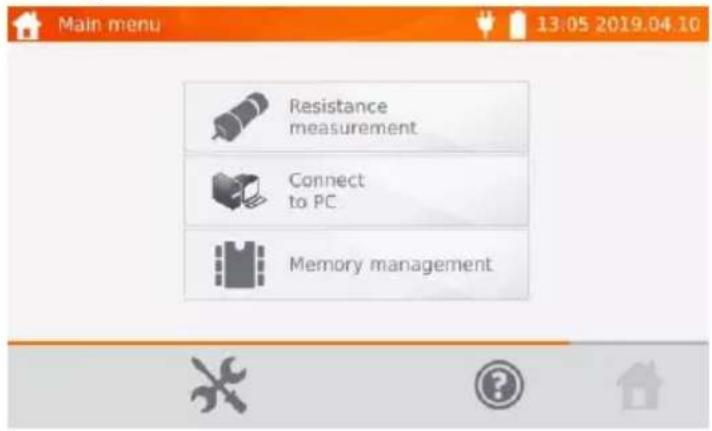
When the meter is turned on, it displays the main menu.
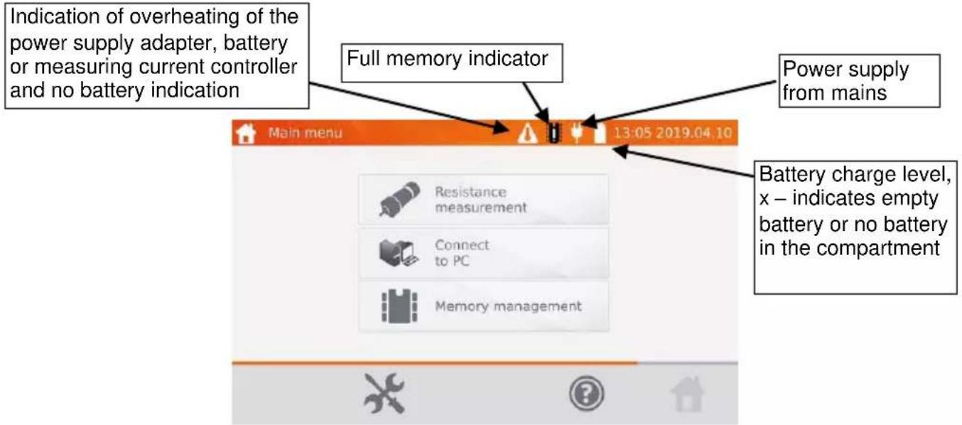
2.1 Meter settings
①
In the main menu, select icon

②
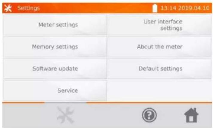
Select Meter settings.
2.1.1 Energy saving
In order to save its rechargeable battery, the meter automatically shuts off or blanks the screen after an adjustable inactivity period.
①
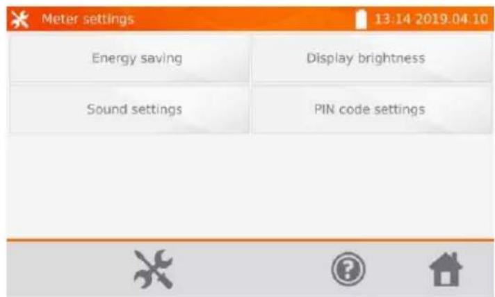
Select Energy saving.

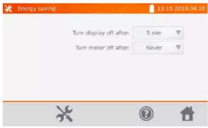
Set the inactivity time for blanking the screen and turning the meter off.
2.1.2 Sound settings

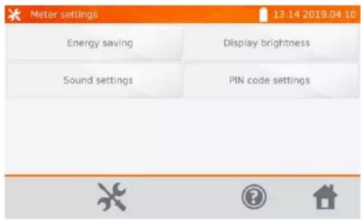
Select Sound settings.

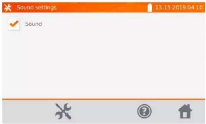
Select the box to turn on ( ) or off the sound signals.
2.1.3 PIN code settings
The PIN code is used for connecting the meter to the computer.
①
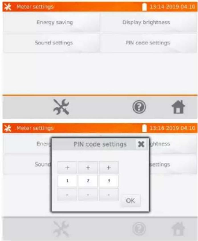
Select PIN code settings.
②
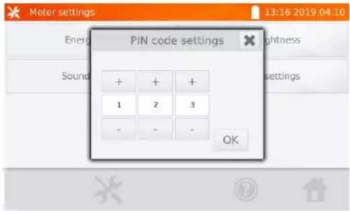
Use + and - icons to set the code and confirm it by pressing OK.
The PIN code is used for communication with PC. The default code is 123.
2.1.4 Display brightness settings
①
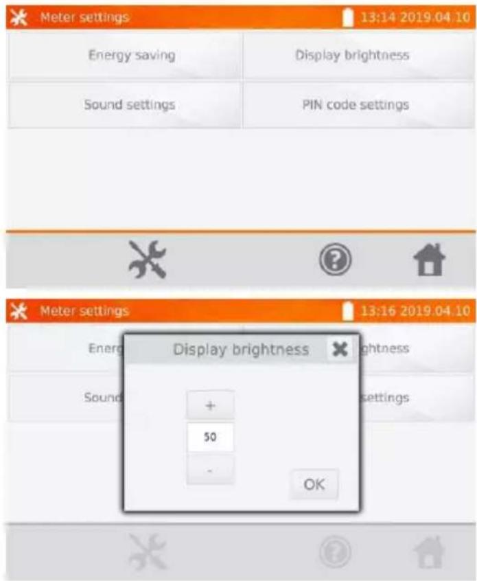
Select Display brightness.
②
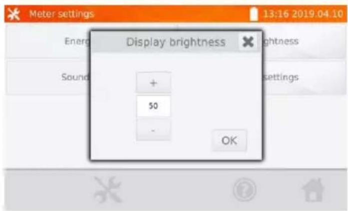
Use + and - icons to set the desired brightness. Confirm it by pressing OK.
2.2 Memory settings
① In the main menu, select icon.

By pressing , icon, you may enter settings or enter the higher level in the settings.
②
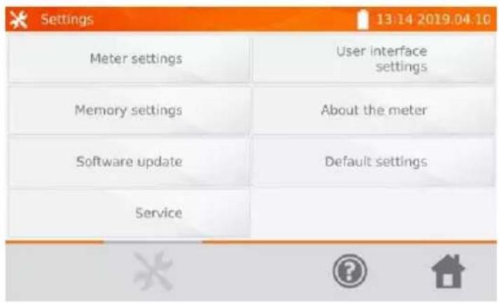
Select Memory settings.
2.2.1 Memory management
①
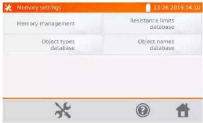
Select Memory management.
②
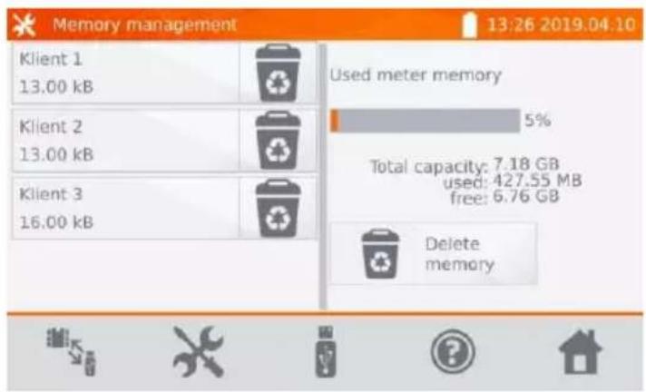
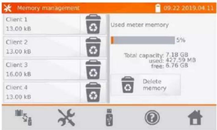
Except reading the % of the used memory, this option allows to clear it. After pressing Delete memory all clients are deleted with their objects and measurement results.
Use icon located at the client to delete individual client.
Use icons / to switch between USB memory and meter memory.
Use icon to initiate the process of copying clients to the USB memory and vice versa.
2.2.2 Object types database
This is a list of types of tested objects.
①
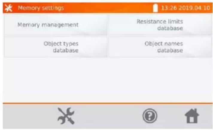
Select Object types database.
②
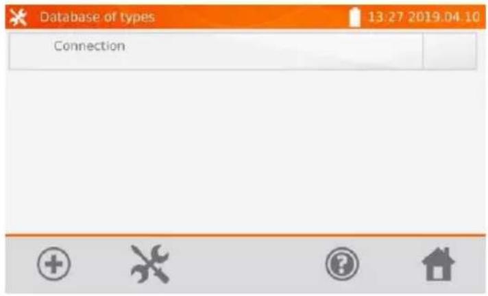
The meter has default types saved in its memory. Use + icon to add a new type of the tested object.
③
![Database of types 1 2 3 4 5 6 7 8 9 0 - = q w e r t y u i o p [ ] a s d f g h j k l ; ' z x c v b n m , . / All](/content/2026/05/938570/images/835db00aec7088aa1fac0ea9f41f1d5c1f438e832ca806914450194c6d4dfa28.jpg)
Enter a new type of the object being tested.
④
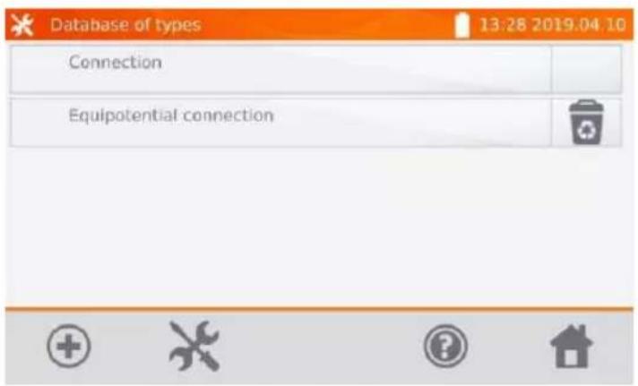
Added types may be deleted by pressing
2.2.3 Object names database
It is a list of names of tested objects or measurement points.
①
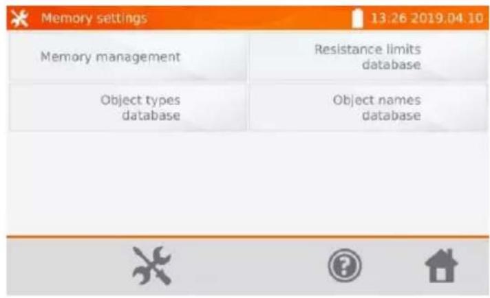
Select Object names database.
②
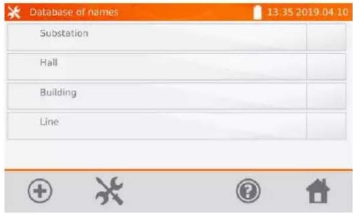
The meter has 4 default names saved in its memory. Use icon to add a new name.
③
![Database of names 1 2 3 4 5 6 7 8 9 0 - = q w e r t y u i o p [ ] a s d f g h j k l ; ' z x c v b n m , . / ↑ Alt ← → ↕](/content/2026/05/938570/images/f6cffa451f6510cef6bbffed0301f935441a32ee9239629b5d73c7f8a4e0c2c6.jpg)
Enter the name of the object.
④
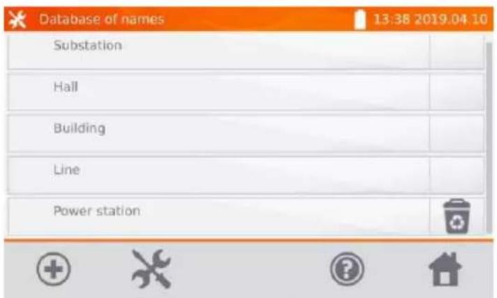
Added names may be deleted by pressing
2.2.4 Resistance limits database
The specified limits may be used to automatically assess the validity of the results of resistance measurements.
①
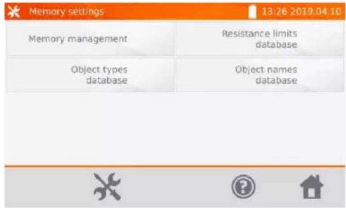
Select Resistance limits database.
②
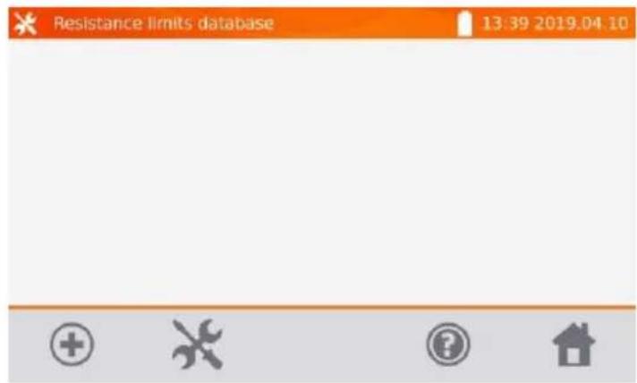
Select to add a new limit.
③
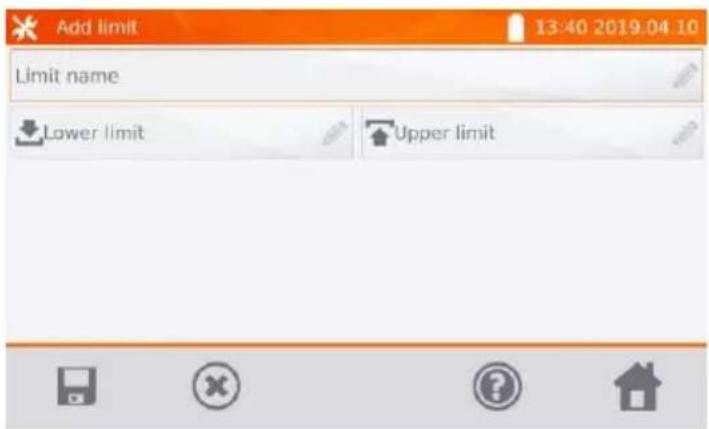
Tap Limit name box.
④
![Add limit 13:40 2019.04.10 Limit name 1 2 3 4 5 6 7 8 9 0 - = q w e r t y u i o p [ ] a s d f g h j k l ; ' z x c v b n m . . / <&I All](/content/2026/05/938570/images/095ade24d8f4a048f344bc593b57f765630781729daa7f88bf58c6fee784656f.jpg)
Enter the name of the limit. Use icon to go to the lower limit setting.
⑤
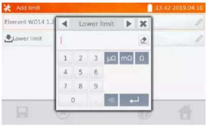
Enter the lower limit. Use icon to go to the upper limit setting. You can set only one of the limits.
⑥
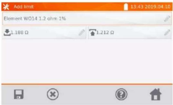
Use to save the limit in the memory. By pressing you may exit without saving.
⑦
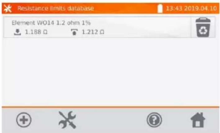
Use to delete the limit.
2.3 Software update
The software of the meter is periodically modified. You may download its current version from www.sonel.pl.

In the main menu, select icon

| Settings 13:14:2019.04.10 | |
| Meter settings | User interface settings |
| Memory settings | About the meter |
| Software update | Default settings |
| Service | |
Select Software update.

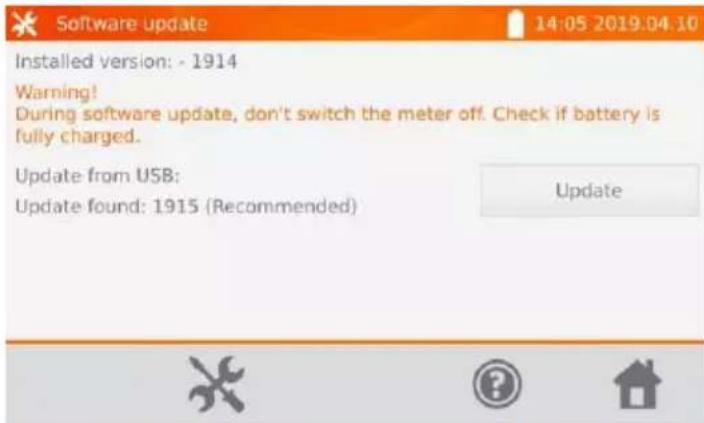
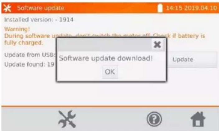
Read the displayed text. To perform an update insert the USB drive with the update files and select Update button.

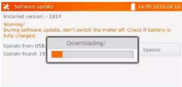
The meter is downloading software.


natural_image
Three gray icons on a light background: screwdriver, question mark, and house (no text or symbols)Select OK to run the update or close the window to cancel.

NOTE!
Update is performed automatically and may be divided into a few stages. During the update, do not turn off the power supply of the meter and do not remove the USB drive. The update process is continued until the meter displays the main menu screen.

Only at this point, you can turn off the power supply of the meter or start its use.
2.4 Service
This function is available for factory servicing and is protected by password.
2.5 User interface settings

In the main menu, select icon


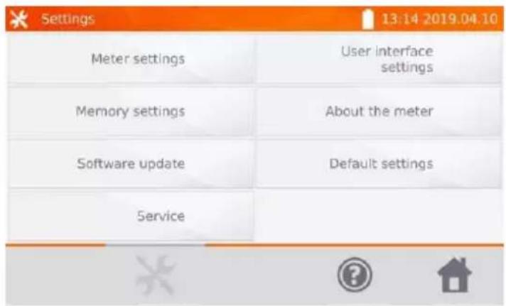
Select User interface settings.
2.5.1 Language selection
①
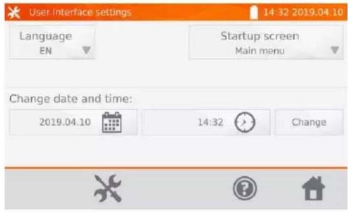
Select Language button.
②
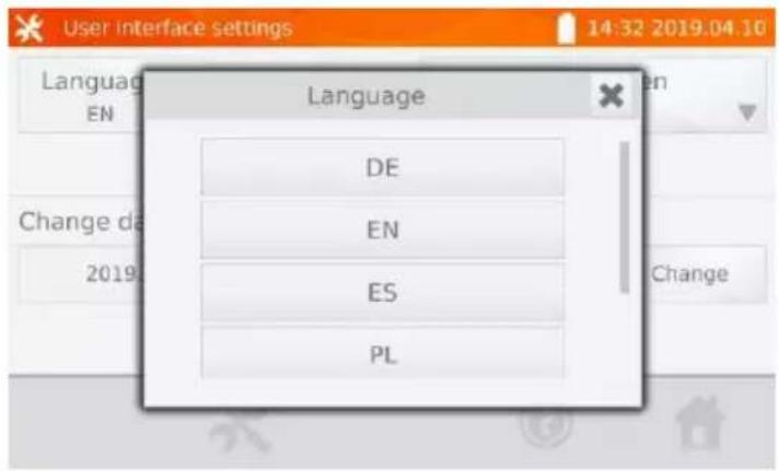
Select the language.
2.5.2 Selecting the startup screen
①
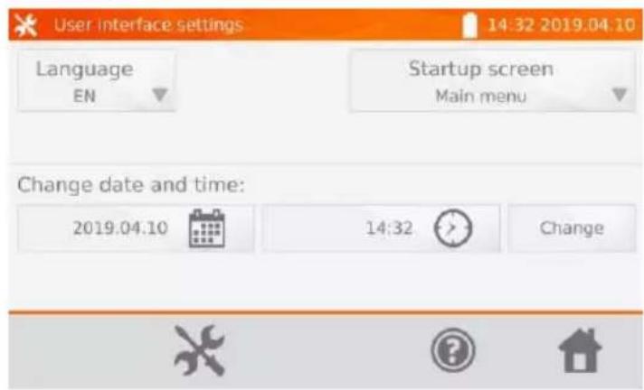
Select Startup screen button.
②
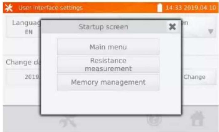
Select the desired startup screen. The screen will be automatically shown after turning the meter on.
2.5.3 Changing the date and time
①
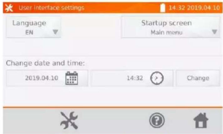
Select date icon.
②
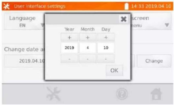
Use + and - icons to set year, month and day, then and confirm it by pressing OK. Similarly, you may set the time. To make changes, select Change button.
2.6 Information about the meter
①
In the main menu, select icon

②
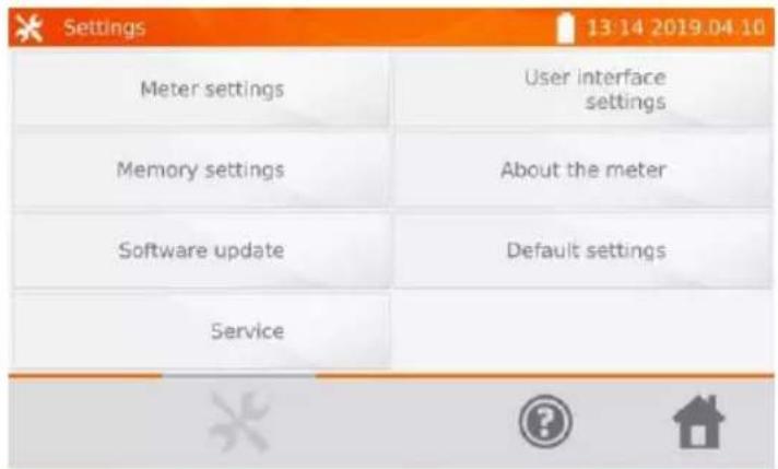
Select About the meter.
③
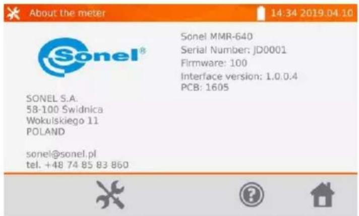
The screen will display information on the meter and its manufacturer.
2.7 Factory (default) settings

In the main menu, select icon


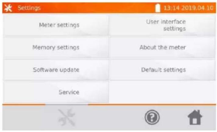
Select Default settings.

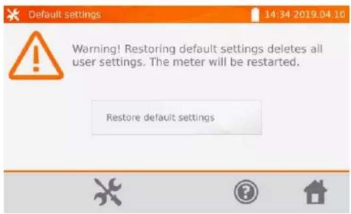
Select Restore default settings to reset the meter.
Select icon to cancel and return to the menu.
The following elements are restored to the default settings:
• measurement settings,
- list of object types,
- list of object names,
- list of R limits,
- list of T limit, sound settings,
- default startup screen,
- PIN code settings,
• energy saving settings,
• display brightness.
2.8 Communication with PC
①
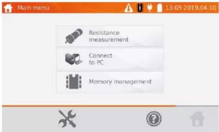
Press Connect to PC.
② On your PC run Sonel Reader or Sonel Reports PLUS.
③ To terminate the connection press ✗
3 Measurements

- If the current test leads are not connected, a message appears: Lack of continuity of current leads.
- If the voltage test leads are not connected, a message appears: Lack of continuity of voltage leads.
①
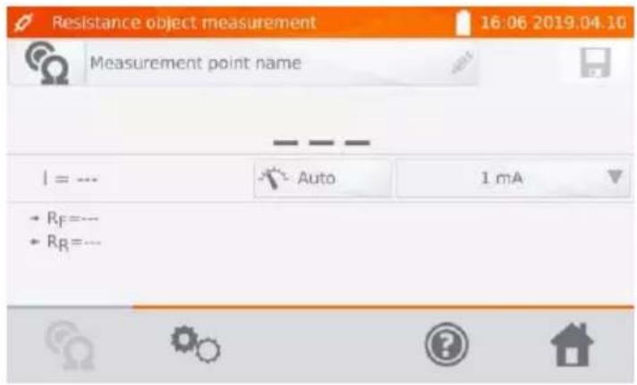
Measurement screen.
②
![Measurement point name Substation Hall Building Line Power station 1 2 3 4 5 6 7 8 9 0 - = q w e r t y u i o p [ ] a s d f g h j k l ; ' z x c v b n m , . / All](/content/2026/05/938570/images/5159eac139a63df9db62d310771640e4427e5024b67f5e4eaf02381aa9d9b41c.jpg)
When necessary, enter the name of the measurement point.

- After entering the name of the measuring point, the measurement result will be saved in the memory - after selecting the client and object (subobject) you may simply select icon to create and save the point automatically.
- If another point already existing in the memory is selected when saving, the name will be overwritten.
③
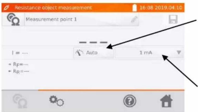
Auto/Manual switching (auto / manual range selection):
Auto - the measuring current is limited to a value not exceeding the set value,
Manual - measuring current has the set value.
Setting the measuring current.

Use icon to go to measurement settings.
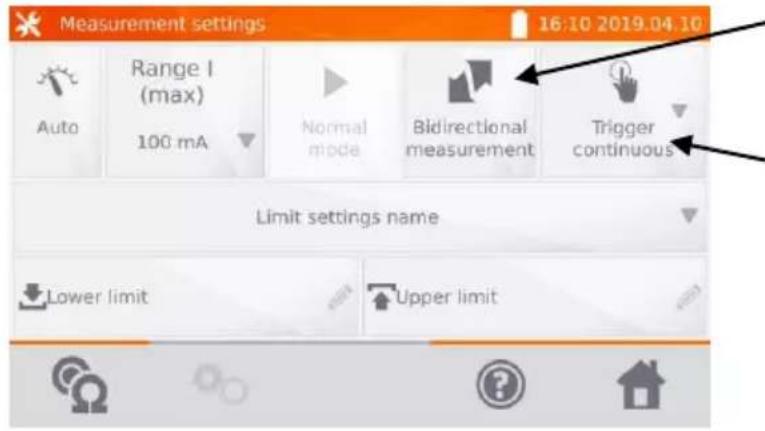
Switching measurement:
- unidirectional,
- bidirectional.
Selecting trigger method:
⇒ manual: use
START/STOP button
⇒ automatic: by connecting test leads to the object,
⇒ continuous: after pressing START/STOP button, the meter measures the resistance in a continuous way to the moment, when the test is terminated by pressing START/STOP button.
Boxes for setting the range and measurement current correspond to the same boxes shown in step .

- Bidirectional measurement is used to compensate the potential present at the contact point of two different conductors. In this case, the main result of the measurement is the average of results from individual directions.
- After selecting automatic trigger, the first measurement must be started by pressing START/STOP button. Next measurements may be initiated by connecting the test leads to the object.
- Automatic trigger operates correctly for resistance ≤ 4 kΩ. Above this value there is no guarantee of correct operation.

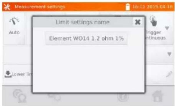
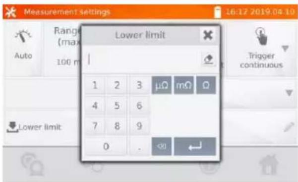
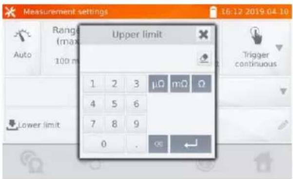
If necessary, select resistance limits from the database (Limit settings name) or set the required limits for the performed measurement by clicking Lower limit and/or Upper limit. To deactivate the limit delete the lower and upper values.

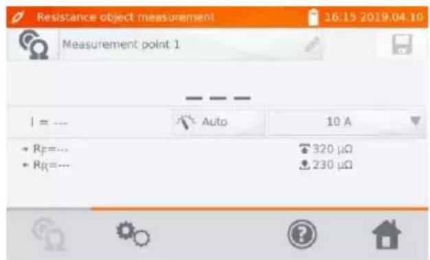
Press icon to go to the measurement.
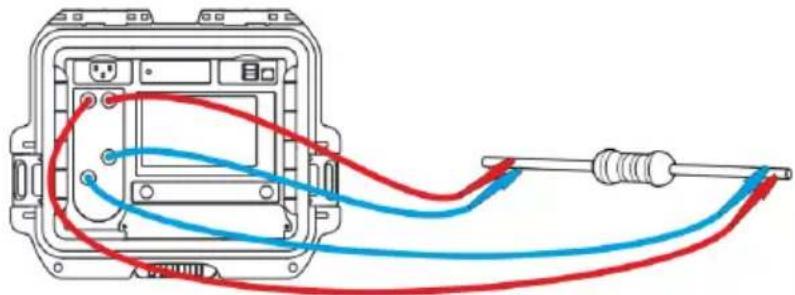
⑦ Connect the meter to the tested object. Press START/STOP button.
natural_image
Diagram of a device's internal wiring with red and blue wires, no text or symbols present
NOTE!
Touch the surface with the double-pin Kelvin probe held perpendicularly to the surface, as any other position may damage the probe.
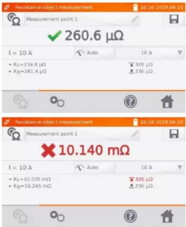
Correct result: R_0 within limits.
Incorrect result" R_0 outside limits.
R_F – resistance at the measuring current flowing in the assumed positive direction
R_R – resistance at the measuring current flowing in the assumed negative direction
- upper limit - lower limit

- The measuring current is obtained from a current source.
- The result may be entered into the memory by pressing icon (see sec. 4.2).
4 Memory
4.1 Memory management (clients, objects, measuring points)

- The memory may be organized before the measurements, or on a regular basis, after the measurement.
- Use 📄 icon to enter the memory management for measurements results, as well as to enter a higher level in the memory.
4.1.1 Entering the clients
①
Select Memory management to enter the memory.
②
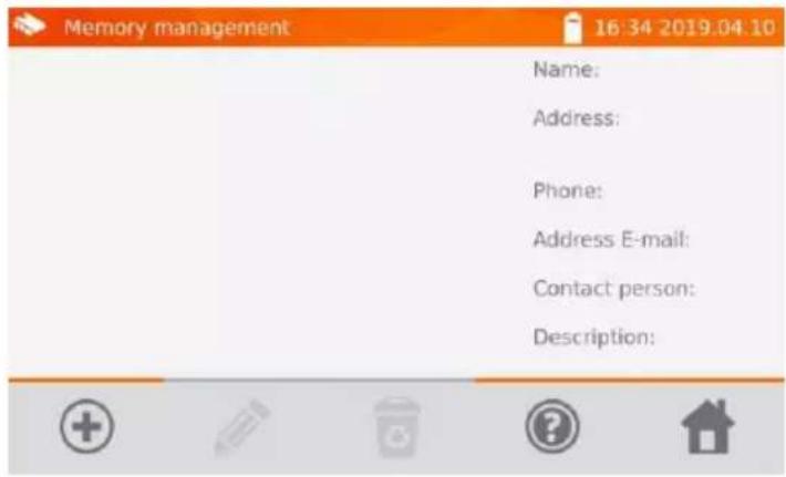
Select to add a client.
③
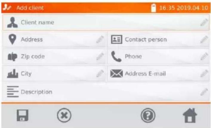
By selecting the individual fields, enter customer data using the keyboard.
Client name (box marked in orange) is mandatory.
④
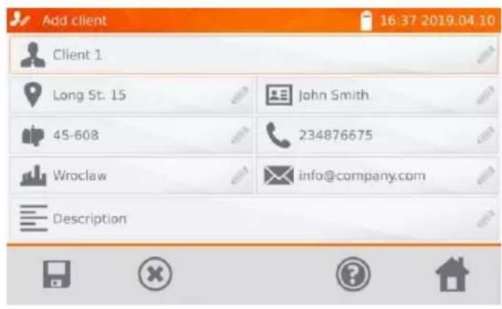
Use icon to save client's data in the memory.
⑤
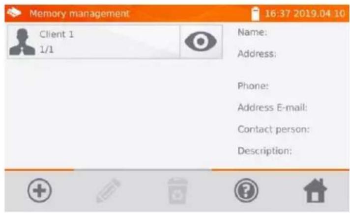
4.1.2 Entering objects, subobjects, measurement points
4.1.2.1 Entering objects and subobjects
①
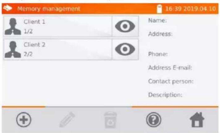
Select associated with the selected client.
②
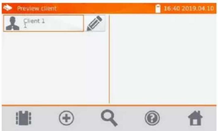
To add an object or measuring point select +
③
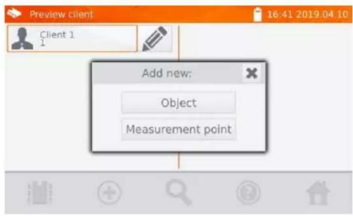
Select Object button.
④
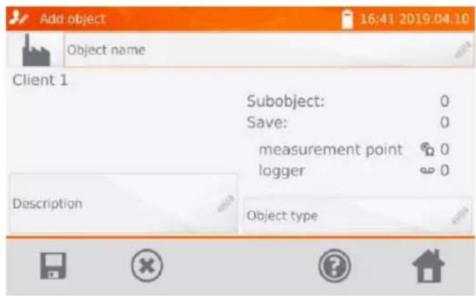
Select Object name box to name the object (mandatory).
⑤
![Object name Substation Hall Building Line Power station 1 2 3 4 5 6 7 8 9 0 - = q w e r t y u i o p [ ] a s d f g h j k l ; ' z x c v b n m , . / All](/content/2026/05/938570/images/9b0b29b76860f8db45b1ef03bc1040f69e8c0d49538d4f1986b181b4595d3e11.jpg)
Select one of the default names or enter your own.
⑥
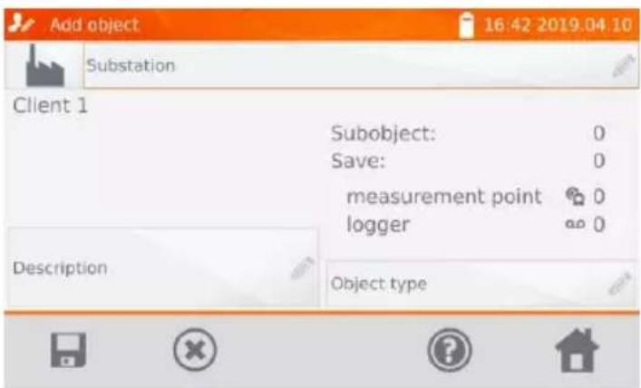
In the box Description you may attach an additional description. In the box Object type box you may select the default type of or enter your own.
⑦
![Object type Connection Equipotential connection 1 2 3 4 5 6 7 8 9 0 - = q w e r t y u i o p [ ] a s d f g h j k l ; ' z x c v b n m , . / All](/content/2026/05/938570/images/a205c9bb143551e5d4f24903479d3becb520ea3c1cb01b9e2bb38387213ddf79.jpg)
Select one of the default names or enter your own.
⑧
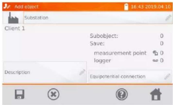
Use icon to save the object into the memory.
⑨
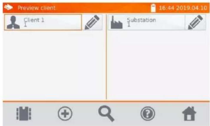
By clicking + you can add more objects.
By clicking the object field and icon, you may enter subobjects in the object etc. - up to 4 levels.
10
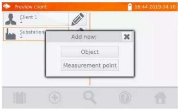
4.1.2.2 Entering measurement points
Measuring points may be entered at any memory level, i.e. at the level of client, object or subobject.
①
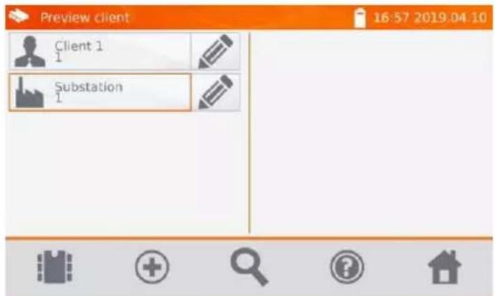
Select
⇒ associated with the client, and then
or
Select Measurement point.
③
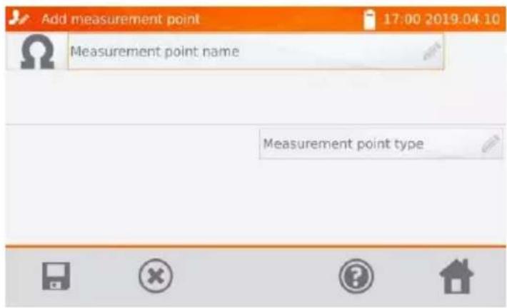
Select Measurement point name box to name the object (mandatory).
④
![Measurement point name Substation Hall Building Line Power station 1 2 3 4 5 6 7 8 9 0 - = q w e r t y u i o p [ ] a s d f g h j k l ; ' z x c v b n m , . / All](/content/2026/05/938570/images/8d1bf466e315ce209ed11ca4a10069fbc49454ffdfd244e5c3b46be9be9e05a6.jpg)
Select one of the default names or enter your own.
⑤
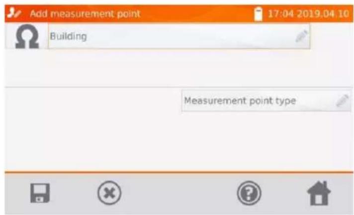
By clicking Measurement point type box, you may select the default type of or enter your own.
⑥
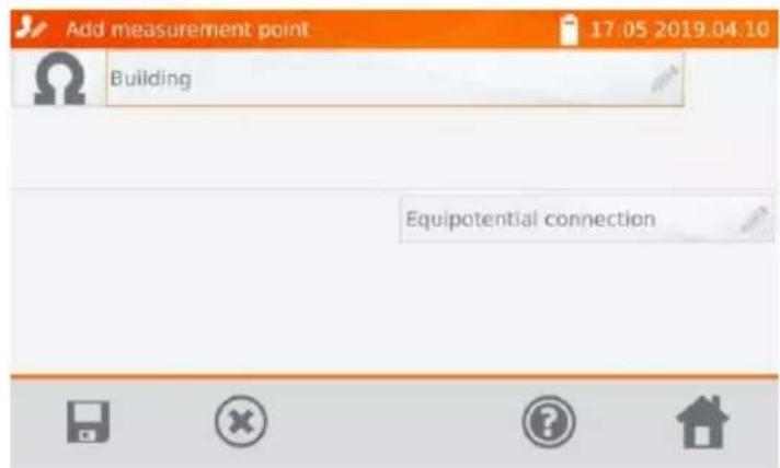
Use icon to save a measuring point to the memory.
⑦
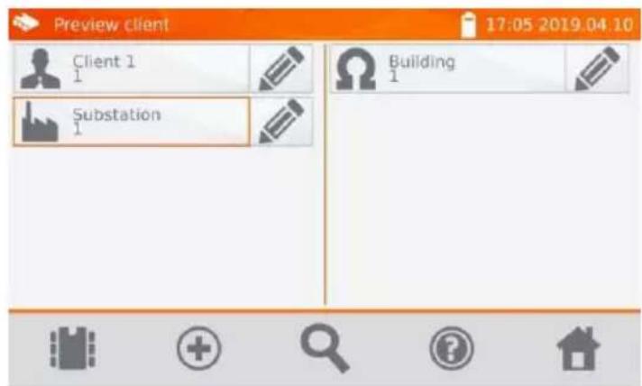
4.2 Storing the measurement results in the memory

NOTE!
- Before performing the next series of measurements at the same measuring points, the previous results must be archived, because for one measuring point, you can save only one result. Entering the next will erase the previous one.
- The measurement result may be entered only to the measuring point or to logger.
4.2.1 Entering the results of measurements with previously organized memory
①
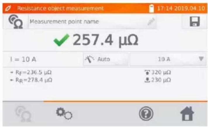
Tap icon after finishing the measurement.
②
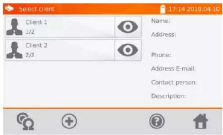
Select the client by tapping icon next to its name.
③
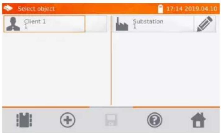
Select the object/subobject.
④
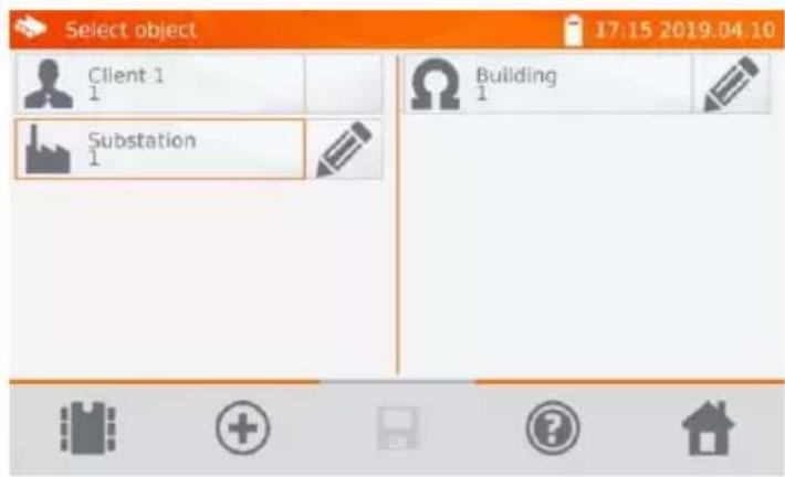
Select the measuring point (indicated by orange border).
⑤
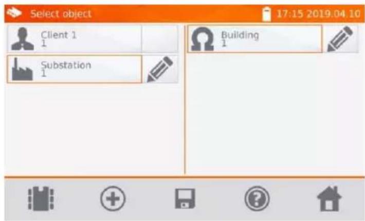
Save the result by selecting icon.
4.2.2 Entering the results of measurements without previously organized memory
4.2.2.1 Method 1
①
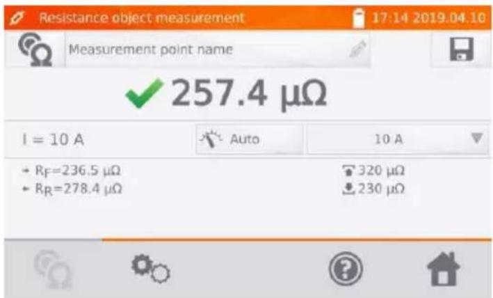
Tap icon after finishing the measurement.
②
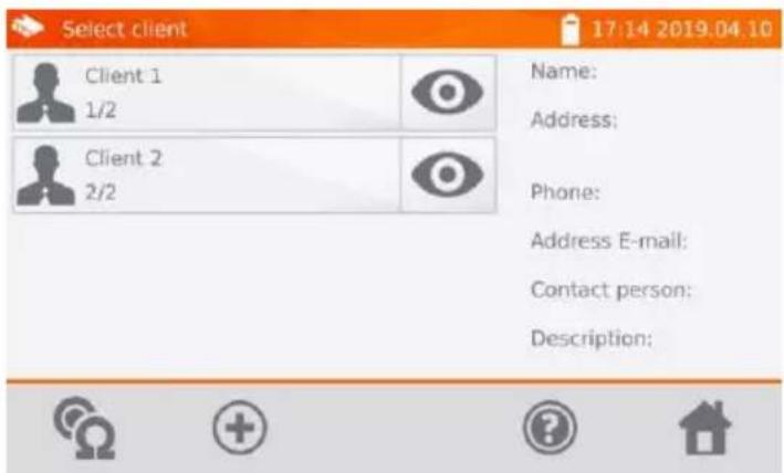
Select icon to add a client.
③
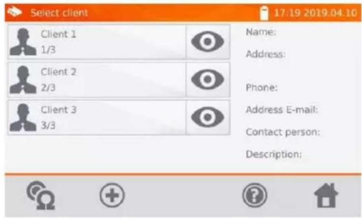
After saving the client:
- select its icon
- and then select icon to add the object.
④
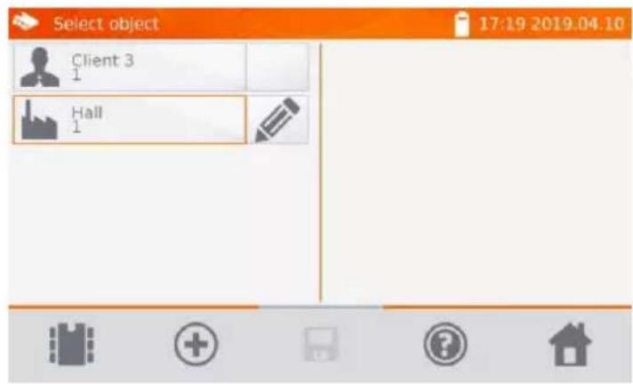
After adding and saving the object (also subobjects if necessary), select to add the measurement point.
⑤
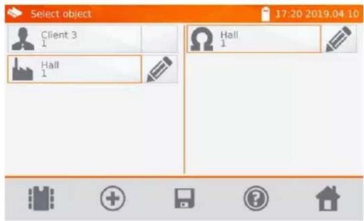
After adding and saving the measuring point, select ☐ The result is saved to memory. The meter returns to the measuring mode.
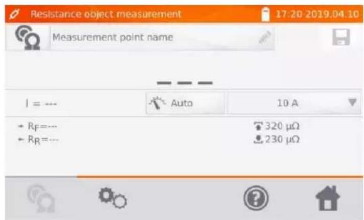
4.2.2.2 Method 2
①
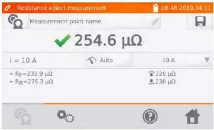
Before or after the measurement select Measurement points name and enter the name.
②
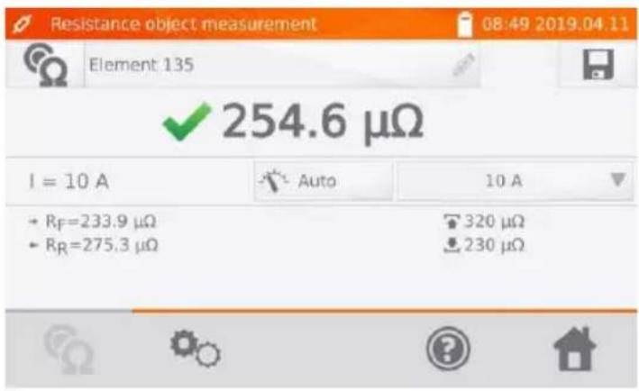
After finishing the measurement press icon.
③
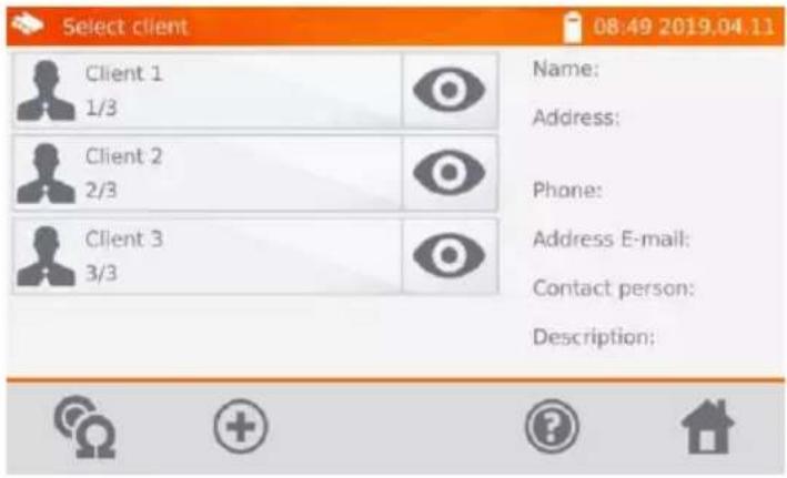
Select to add a client.
④
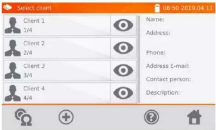
After saving the client:
- select icon next to its name
- and then select icon to add the object.

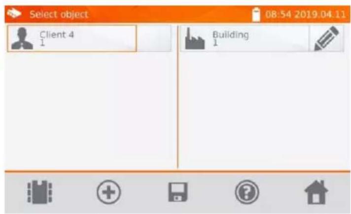
After adding and saving the object (also subobjects according to the needs), select the object and then The measuring point with the measurement result will be saved automatically.

Having selected the client and object (subobjects) and performing a series of measurements on one object, after the measurement and entering the name of the measuring point, select and - on the displayed screen - select again . The measuring point with the measurement result will be saved automatically.
4.3 Viewing memory data

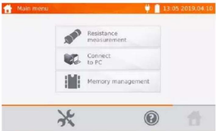
Select Memory management.

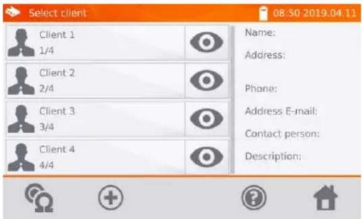
Select of the selected object and then select on the object, subobjects and measuring point.

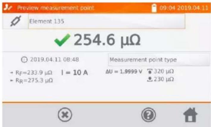
4.4 "Search" in the memory
①
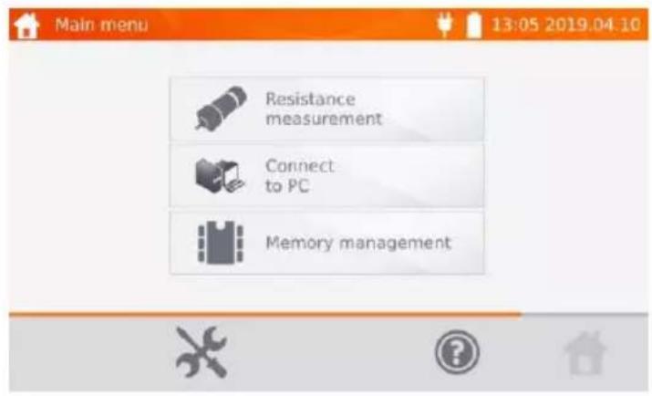
Select Memory management.
②
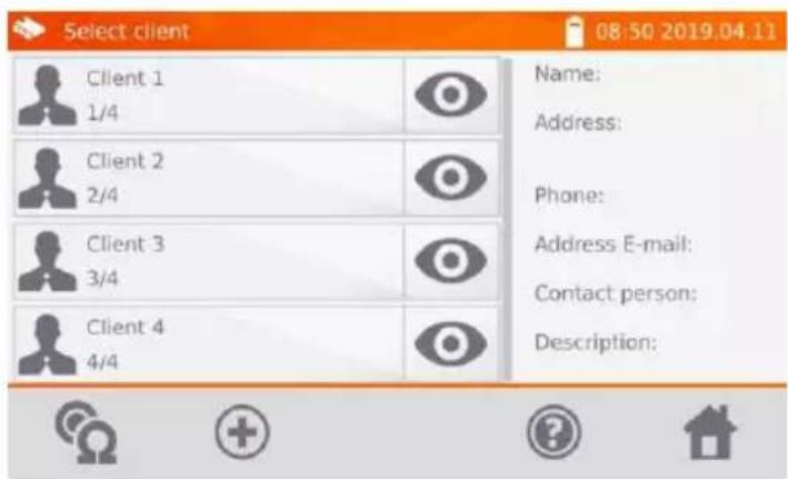
Select of the desired client.
③
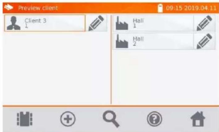
In any of the client's window, select icon.
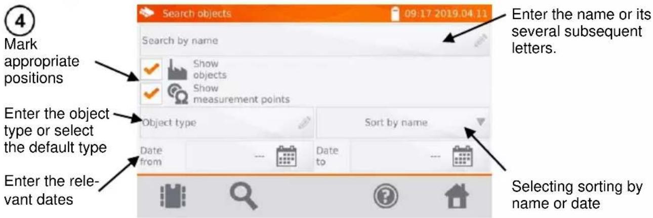

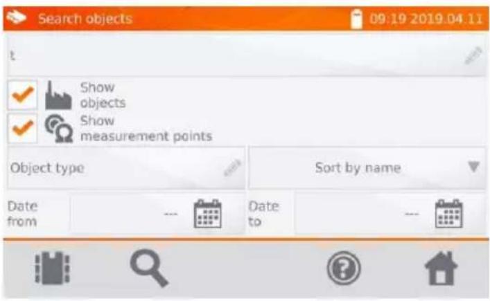
After entering all the search criteria, select icon again.

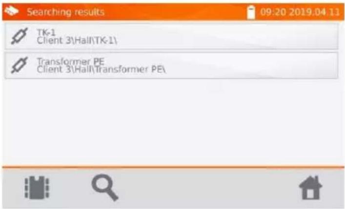
Search results.

- To perform the search, enter the name (or its part) or one of the dates.
- The size of letters in the name of searched item is ignored.
4.5 Copying client data from the memory to USB stick and vice versa
①
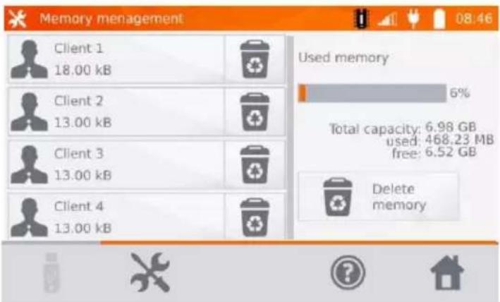
In the main menu, select, then Memory settings and Memory management.

②
Insert the USB stick into the appropriate USB slot of the meter.
③
Select icon.
④
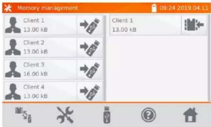
⇒ Select to save data in the USB stick. ⇒ Select to copy data from the USB stick to the memory of the meter.
4.6 Deleting data
4.6.1 Deleting the meter's memory data
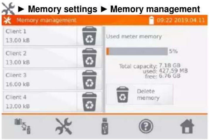
To delete the whole memory, select Delete memory button.
4.6.2 Deleting a client
①
or
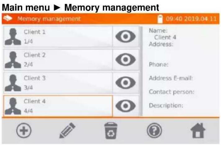
To delete a client: ⇒ in location 1 select a client and then icon at the bottom bar, ⇒ in location 2 select icon associated with its name.
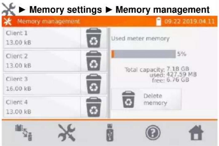
②
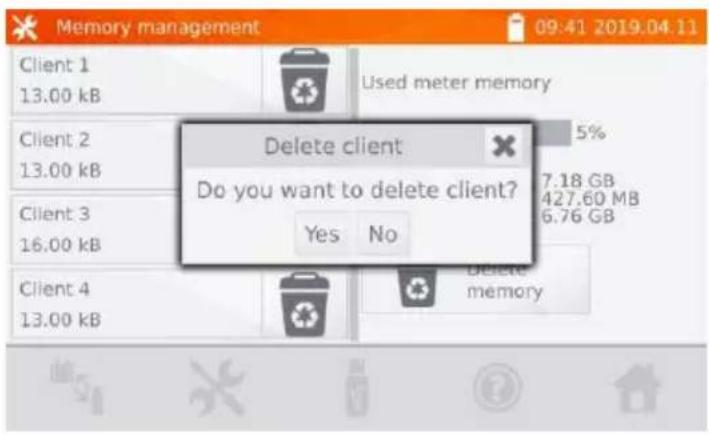
Select Yes to confirm deleting or No to cancel it.
4.6.3 Deleting an object
①

To delete an object or measuring point:
- go to location Main menu Memory management
- using 📄 icon go to the client's content,
- using icon start to edit the selected object...
②
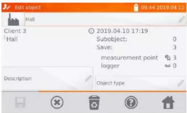
...and then select
③
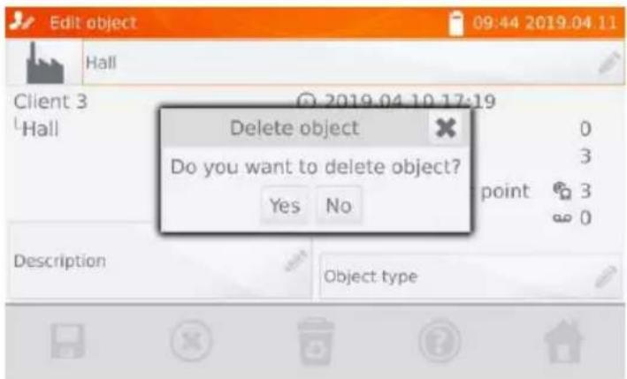
Select Yes to confirm deleting or No to cancel it.
5 Power supply
The meter is powered by an AC adapter or a battery pack. When supplied from the mains, the battery pack is charged.
5.1 Monitoring the power supply voltage
The charge level of the battery pack is indicated by the symbol in the right upper corner of the display on a current basis:

the battery pack is charged

the battery pack is discharged

the battery pack is being charged

NOTE!
Remember that measurements performed with an insufficient supply voltage feature additional errors which the user is unable to evaluate. Consequently, such measurements cannot prove that the results of resistance measurements are correct.
5.2 Replacing the battery pack
MMR-640 is equipped with a rechargeable lithium-ion battery pack and a charger. The battery pack is placed in the battery compartment. Battery charger is installed inside the housing of the meter and is compatible only with the manufacturer's rechargeable battery pack.
WARNING
If the power cord is left in the socket during replacement of the battery pack, there is a risk of electric shock with a dangerous voltage.
In order to replace the batter-pack it is necessary to:
- remove all the test leads from the sockets and turn the meter off,
- remove the lid of the battery compartment (in the upper part of the housing) by removing 2 screws,
- remove the battery pack,
- remove two connector pins of the battery pack,
- connect the power plugs of the new battery pack,
- insert the battery pack into the battery compartment,
- place and tighten the lid of battery compartment.

NOTE!
Do not operate a meter with an open or incorrectly closed battery compartment and do not power it from other sources than those specified in this manual.
5.3 General rules for using Li-Ion rechargeable batteries
- If you do not use the device for a prolonged period of time, then it is recommended to remove the rechargeable batteries and store them separately.
- Store the half-charged battery pack in a plastic container placed in a dry, cool and well ventilated place and protect them from direct sunlight. The battery pack may be damaged if stored when fully discharged. The ambient temperature for prolonged storage should be maintained within the range of 5°C...25°C.
- Charge the batteries in a cool, well-ventilated place at a temperature of 10^ C ... 28^ C. Modern fast chargers detect both too low and too high temperature of rechargeable batteries and react to the situation adequately. Too low temperature should prevent starting the process of charging, which might irreparably damage rechargeable batteries. The increase in temperature of the battery pack may cause electrolyte leakage and even its ignition or explosion.
- Do not exceed the charging current, as it may result in ignition or "swelling" of the battery pack. "Swollen" battery pack must not be used.
- Do not charge or use the batteries in extreme temperatures. Extreme temperatures reduce the lifetime of rechargeable batteries. Always observe the rated operating temperature. Do not dispose the battery pack into fire.
- Li-Ion cells are sensitive to mechanical damage. That may cause its permanent damage of the batteries and thus - ignition or explosion. Any interference in the structure of Li-ion battery pack may cause its damage. This may result in the ignition or explosion. A short-circuit of the battery poles + and - may permanently damage the battery pack or even cause its fire or explosion.
- Do not immerse Li-Ion battery in liquids and do not store in humid conditions.
- If the electrolyte contained in the Lithium-Ion battery pack, contacts eyes or skin, immediately rinse the affected place with plenty of water and consult a doctor. Protect the battery against unauthorised persons and children.
- When you notice any changes in the Lithium-Ion battery pack (e.g. changes in colour, swelling, excessive temperature), stop using it. Mechanical damaged, overcharged or excessively discharged battery pack is not suitable for use.
- Any misuse of the battery may cause its permanent damage. This may result in the ignition. The seller and the manufacturer shall not be liable for any damages resulting from improper handling Li-lon battery pack.
6 Cleaning and maintenance

NOTE!
Use only the maintenance methods specified by the manufacturer in this manual.
The casing of the meter may be cleaned with a soft, damp cloth using all-purpose detergents. Do not use any solvents or cleaning agents which may scratch the casing (powders, pastes, etc.). The electronic system of the meter does not require maintenance.
7 Storage
In the case of storage of the device, the following recommendations must be observed:
- disconnect all the test leads from the meter.
• make sure that the meter and accessories are dry,
• during prolonged storage remove the batteries, - storage temperatures must be in accordance with those defined in technical specifications,
- in order to prevent total discharge of the rechargeable batteries during prolonged storage, charge them from time to time.
8 Dismantling and disposal
Worn-out electric and electronic equipment should be gathered selectively, i.e. it must not be placed with waste of another kind.
Worn-out electronic equipment should be sent to a collection point in accordance with the law of waste electrical and electronic equipment.
Before the equipment is sent to a collection point, do not dismantle any elements.
Observe the local regulations concerning disposal of packages, worn-out batteries and accumulators.
9 Technical data
9.1 Basic data
⇒ Abbreviation "m.v." used in the specification of measurement accuracy means a standard measured value.
Uncertainty values stated in the table refer to the measurement with bidirectional current and relate to the average of two measurements according to the following formula:
$$ R = \frac {R _ {F} + R _ {R}}{2} $$
where:
R_F — resistance at the assumed "forward" current direction,
R_R — resistance at the assumed "backward" current direction.
For measuring with unidirectional current, the specified accuracy is not guaranteed.
Resistance measurements of resistive objects
| Range | Resolution | Accuracy | Measuring current |
| 0...999.9 μΩ | 0.1 μΩ | ±(0.25% m.v. + 2 digits) | 10 A |
| 1.0000...1.9999 mΩ | 0.0001 mΩ | ||
| 2.000...19.999 mΩ | 0.001 mΩ | 10 A | |
| 20.00...199.99 mΩ | 0.01 mΩ | 10 A / 1 A | |
| 200.0...999.9 mΩ | 0.1 mΩ | 1 A / 0.1 A | |
| 1.0000...1.9999 Ω | 0.0001 Ω | ||
| 2.000...19.999 Ω | 0.001 Ω | 0.1 A | |
| 20.00...199.99 Ω | 0.01 Ω | 10 mA | |
| 200.0...1999.9 Ω | 0.1 Ω | 1 mA |
Resistance measurement in the presence of noise of 50 Hz or 60 Hz
| Signal/noise ratio | Additional uncertainty | Signalling |
| N ≥ 0.02 | - | - |
| 0.02 > N ≥ 0.004 | 1% |  |
| N < 0.004 | unspecified |  |
Measuring current settings
Resistance measurements of resistive objects: 1 mA, 10 mA, 100 mA, 1 A, 10 A
9.2 Other technical data
a) insulation type acc. to EN 61010-1 double
b) measurement category acc. to EN 61010-2-030....III 600 V

NOTE!
With the use of 10 m or 25 m measurement leads with a crocodile - CAT III 50 V.
c) ingress protection acc. to EN 60529
- with closed housing IP67
- with open housing, powered from the battery pack, installed plugs....IP54
- with open housing, powered from mains and/or without plugs IP40
d) protection against external voltage up to 600 V AC for 10 s
e) power supply Li-Ion rechargeable battery 7.2 V 8.8 Ah
f) power supply to battery charger....90 V...265 V, 50 Hz...60 Hz, 2 A
g) battery charging time......approximately 3.5 hours
h) number of measurements with 10 A current when powered from the battery pack ....700..800, depending on the ambient temp.
i) maximum wire resistance for 10 A current....300 mΩ
j) accuracy of measuring current setting ....±10%
k) time of performing the resistance measurement with bidirectional current flow 3 s
l) dimensions 318 x 257 x 152 mm
m) meter weight.... approx. 3.5 kg
n) operating temperature ....-10°C...+50°C
o) charger operating temperature 0°C...+45°C
p) storage temperature ....-20°C...+60°C
q) humidity....20%..90%
r) reference temperature ....+23°C ± 2°C
s) reference humidity....40%...60%
t) altitude (above sea level): .... .... .... .... .... .... .... .... .... .... .... .... .... .... .... .... .... .... .... .... .... .... .... .... .... .... .... .... .... .... .... .... .... .... .... .... .... .... .... .... .... .... .... .... .... .... .... .... .... .. <2000 m
u) time to AUTO-OFF 5..45 minutes or inactive
v) TFT graphic display ......graphical TFT, 800 x 480 points
w) interface standard ....USB
x) quality standard ......design and manufacturing are ISO 9001 compliant
y) the product meets the EMC requirements (emission for industrial environment) according to: .....
EN 61326-1 and EN 61326-2-2
10 Manufacturer
The manufacturer of the device and provider of guarantee and post-guarantee service:
SONEL S.A.
Wokulskiego 11
58-100 Świdnica
Poland
tel. +48 74 884 10 53 (Customer Service)
e-mail: customerservice@sonel.com
web page: www.sonel.com

NOTE!
Service repairs must be performed only by the manufacturer.
NOTES
NOTES
SYMBOLS DISPLAYED BY THE METER
Memory

Settings

Return to the main menu

Adding a client, object or measuring point

Entry to client objects

Entry to client edition, object or measurement point with a possibility of changing data

Fast entry deletion on the on-screen keyboard

Deletion of a measurement point, object or client

Measuring Mode

Measurement setup mode

Saving to memory

Help

Exit from the option

Searching for an object or measurement point

There was a limitation of the measuring current to a value lower than that ensuring maximum accuracy

Test leads interchanged

High level of noise (interference), measurement possible with additional uncertainty

High level of noise (interference), measurement possible without defining uncertainty
SONEL S.A.
Wokulskiego 11
58-100 Świdnica
Poland
Customer Service
tel. +48 74 884 10 53
e-mail: customerservice@sonel.com
www.sonel.com
- USER MANUAL
- LOW RESISTANCE METER
- MMR-640
- CONTENTS
- Safety 5
- General settings - menu 6
- Measurements....20
- Memory 23
- Power supply....39
- Cleaning and maintenance 40
- Storage....40
- Safety
- General settings - menu
- Meter settings
- Energy saving
- Sound settings
- PIN code settings
- Display brightness settings
- Memory settings
- Memory management
- Object types database
- Object names database
- Resistance limits database
- Software update
- NOTE!
- Service
- User interface settings
- Language selection
- Selecting the startup screen
- Changing the date and time
- Information about the meter
- Factory (default) settings
- Communication with PC
- Measurements
- Memory
- Memory management (clients, objects, measuring points)
- Entering the clients
- Entering objects, subobjects, measurement points
- Entering objects and subobjects
- Entering measurement points
- Select
- Storing the measurement results in the memory
- Entering the results of measurements with previously organized memory
- Entering the results of measurements without previously organized memory
- Method 1
- Method 2
- Viewing memory data
- "Search" in the memory
- Copying client data from the memory to USB stick and vice versa
- Deleting data
- Deleting the meter's memory data
- Deleting a client
- Deleting an object
- Power supply
- Monitoring the power supply voltage
- Replacing the battery pack
- WARNING
- General rules for using Li-Ion rechargeable batteries
- Cleaning and maintenance
- Storage
- Dismantling and disposal
- Technical data
- Basic data
- Measuring current settings
- Other technical data
- Manufacturer
- SONEL S.A.
- SYMBOLS DISPLAYED BY THE METER
- Customer Service
Brand : Sonel
Model : MMR-640
Category : Measurement