Pick your language and provide your email: we'll send you a specifically translated version.
This manual is not available in your language
Product Type
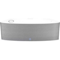
Portable Bluetooth Speaker
Brand
Hanwha
Model
SPA-H100B
Dimensions (W x H x D)
200 mm x 100 mm x 100 mm
Weight
1.2 kg
Power Source
Built-in rechargeable lithium-ion battery
Battery Life
Up to 10 hours at moderate volume
Charging Time
Approximately 3 hours
Bluetooth Version
5.0
Wireless Range
Up to 10 meters
Audio Inputs
Bluetooth, AUX (3.5 mm), USB-A (music playback)
Supported Audio Formats
MP3, WMA, WAV, FLAC
FM Radio
Yes, with built-in antenna
Speaker Configuration
Full-range driver + passive radiator
Output Power
20W RMS
Frequency Response
60 Hz - 20 kHz
Water Resistance
IPX5 (splash proof)
Controls
Power, Volume +/-, Play/Pause, Next/Previous, Mode, Bluetooth pairing
Microphone
Built-in for hands-free calling
Cleaning Instructions
Wipe with a soft, dry cloth. Do not use abrasive cleaners.
Safety Precautions
Do not expose to extreme temperatures. Keep away from water (unless IPX5 rated). Do not disassemble.
Spare Parts Availability
Contact Hanwha support for replacement battery or charging cable.
Repairability
Battery and USB port replaceable by qualified technician.
Included Accessories
USB charging cable, AUX cable, user manual
Frequently Asked Questions - SPA-H100B Hanwha
How do I pair my phone with the speaker via Bluetooth?
Turn on the speaker and press the Bluetooth button until the indicator flashes. On your phone, enable Bluetooth and select 'SPA-H100B' from the list. If prompted, enter '0000' as the PIN.
How do I charge the speaker?
Connect the included USB charging cable to the speaker's charging port and plug the other end into a USB power adapter (5V, 2A). The LED indicator will turn red while charging and go off when fully charged.
Can I use the speaker while it is charging?
Yes, you can use the speaker while it is connected to a power source. However, charging time may be longer if you are playing music at high volume.
What is the battery life and how long does it take to charge?
The battery lasts up to 10 hours at moderate volume. Full charging takes approximately 3 hours.
How do I switch between Bluetooth, AUX, USB, and FM modes?
Press the Mode button repeatedly to cycle through Bluetooth, AUX, USB (if USB drive connected), and FM radio modes. The current mode will be indicated by the speaker's LED color or voice prompt.
Can I connect two speakers together for stereo sound?
This model does not support TWS (True Wireless Stereo) pairing. For stereo sound, use the AUX output with a wired connection to another speaker.
How do I clean the speaker?
Use a soft, dry cloth to wipe the exterior. Avoid using water, solvents, or abrasive cleaners. Do not insert objects into the speaker grille.
What should I do if the speaker does not turn on?
First, charge the speaker for at least 30 minutes. If it still does not turn on, try a different charging cable and adapter. If the issue persists, contact Hanwha customer support.
Is the speaker waterproof?
The speaker has an IPX5 rating, meaning it is splash-proof but not fully waterproof. It can withstand light rain or sweat, but should not be submerged in water.
Can I replace the battery myself?
The battery is internal and not user-replaceable. For battery replacement, please contact Hanwha service center or a qualified technician to avoid damage.
User questions about SPA-H100B Hanwha
0 question about this device. Answer the ones you know or ask your own.
Ask a new question about this device
No questions yet. Be the first to ask one.
Download the instructions for your Loudspeaker in PDF format for free! Find your manual SPA-H100B -
Hanwha and take your electronic device back in hand. On this page are published all the documents necessary for the use of your device. SPA-H100B by Hanwha.
Each of trademarks herein is registered. The name of this product and other trademarks mentioned in this manual are the registered trademark of their respective company.
Restriction
Copyright of this document is reserved. Under no circumstances, this document shall be reproduced, distributed or changed, partially or wholly, without formal authorization.
Disclaimer
Hanwha Vision makes the best to verify the integrity and correctness of the contents in this document, but no formal guarantee shall be provided. Use of this document and the subsequent results shall be entirely on the user's own responsibility. Hanwha Vision reserves the right to change the contents of this document without prior notice.
※ Appearance, specification, etc. of the product is subject to change for performance Improvements without prior notice. The latest update is available on the official Hanwha Vision website. (www.HanwhaVision.com)
The ID for the initial login is "admin," and a password should be set. Please change your password every three months to protect your personal data and prevent identity theft. Please note that users are responsible for the security and other issues caused by insufficient password management.
overview
WARNING
TO REDUCE THE RISK OF FIRE OR ELECTRIC SHOCK, DO NOT EXPOSE THIS PRODUCT TO RAIN OR MOISTURE. DO NOT INSERT ANY METALLIC OBJECT THROUGH THE VENTILATION GRILLS OR OTHER OPENINGS ON THE EQUIPMENT.
Apparatus shall not be exposed to dripping or splashing and that no objects filled with liquids, such as vases, shall be placed on the apparatus.
To prevent injury, this apparatus must be securely attached to the Wall/ceiling in accordance with the installation instructions.
CAUTION
CAUTION
RISK OF ELECTRIC SHOCK.
DO NOT OPEN
CAUTION : TO REDUCE THE RISK OF ELECTRIC SHOCK.
DO NOT REMOVE COVER (OR BACK).
NO USER SERVICEABLE PARTS INSIDE.
REFER SERVICING TO QUALIFIED SERVICE PERSONNEL.
EXPLANATION OF GRAPHICAL SYMBOLS
The lightning flash with arrowhead symbol, within an equilateral triangle, is intended to alert the user to the presence of “dangerous voltage” within the product’s enclosure that may be of sufficient magnitude to constitute a risk of electric shock to persons.
The exclamation point within an equilateral triangle is intended to alert the user to the presence of important operating and maintenance (servicing) instructions in the literature accompanying the product.
CAUTION
RISK OF EXPLOSION IF BATTERY IS REPLACED BY AN INCORRECT TYPE. DISPOSE OF USED BATTERIES ACCORDING TO THE INSTRUCTIONS.
ATTENTION
IL Y A RISQUE D'EXPLOSION SI LA BATTERIE EST REMPLACÉE PAR UNE BATTERIE DE TYPE INCORRECT.
METTRE AU REBUT LES BATTERIES USAGÉES CONFORMÉMENT AUX INSTRUCTIONS.
These servicing instructions are for use by qualified service personnel only.
To reduce the risk of electric shock do not perform any servicing other than that contained in the operating instructions unless you are qualified to do so.
The ITE is to be connected only to (PoE/PoE+) networks without routing to the outside plant.
The wired LAN hub providing power over the Ethernet (PoE/PoE+) in accordance with IEEE 802.3af/at shall be a UL Listed device with the output evaluated as a Limited Power Source as defined in UL60950-1 or PS2 as defined in UL62368-1.
Unit is intended for installation in a Network Environment 0 as defined in IEC TR 62102. As such, associated Ethernet wiring shall be limited to inside the building.
IMPORTANT SAFETY INSTRUCTIONS
Read these instructions.
Keep these instructions.
Heed all warnings.
Follow all instructions.
Do not use this apparatus near water.
Clean the contaminated area on the product surface with a soft, dry cloth or a clamp cloth.
(Do not use a detergent or cosmetic products that contain alcohol, solvents or surfactants or oil constituents as they may deform or cause damage to the product.)
Do not block any ventilation openings, Install in accordance with the manufacturer's instructions.
Do not install near any heat sources such as radiators, heat registers, stoves, or other apparatus (including amplifiers) that produce heat.
Do not defeat the safety purpose of the polarized or grounding-type plug. A polarized plug has two blades with one wider than the other. A grounding type plug has two blades and a third grounding prong. The wide blade or the third prong are provided for your safety. If the provided plug does not fit into your outlet, consult an electrician for replacement of the obsolete outlet.
Protect the power cord from being walked on or pinched particularly at plugs, convenience receptacles, and the point where they exit from the apparatus.
Only use attachments/ accessories specified by the manufacturer.
Use only with the cart, stand, tripod, bracket, or table specified by the manufacturer, or sold with the apparatus. When a cart is used, use caution when moving the cart/ apparatus combination to avoid injury from tip-over.
To prevent injury, this apparatus must be securely attached to the Wall/ceiling in accordance with the installation instructions.
Unplug this apparatus during lighting storms or when unused for long periods of time.
Refer all servicing to qualified service personnel. Servicing is required when the apparatus has been damaged in any way, such as power-supply cord or plug is damaged, liquid has been spilled or objects have fallen into the apparatus, the apparatus has been exposed to rain or moisture, does not operate normally, or has been dropped.
This product is intended to be supplied by a Listed Power Supply Unit marked "Class 2" or "LPS" or "PS2" and rated from PoE(802.3af) : 44V-57V, max 300mA / PoE+(802.3af) : 50V-57V max 510mA.
This product is intended to be supplied by isolation power.
If you use excessive force when installing the product, the product may be damaged and malfunction. If you forcibly install the product using non-compliant tools, the product may be damaged.
Do not install the product in a place where chemical substances or oil mist exists or may be generated. As edible oils such as soybean oil may damage or warp the product, do not install the product in the kitchen or near the kitchen table.
This may cause damage to the product.
When installing the product, be careful not to allow the surface of the product to be stained with chemical substance.
Some chemical solvents such as cleaner or adhesives may cause serious damage to the product's surface
If you install/disassemble the product in a manner that has not been recommended, the production functions/performance may not be guaranteed.
4_ overview
Do not install on a surface where it is exposed to direct sunlight, near heating equipment or heavy cold area.
Do not place this apparatus near conductive material.
Do not attempt to service this apparatus yourself.
Do not place a glass of water on the product.
Do not install near any magnetic sources.
Do not place heavy items on the product.
Please wear protective gloves when installing/removing the product. The high temperature of the product surface may cause a burn.
This device has been verified using STP cable. The use of appropriate GND grounding and STP cable is recommended to effectively protect your product and property from transient voltage, thunderstroke, communication interruption.
In particular installation environments, there might be interference in radio communications. When interference of electromagnetic waves occurs between the product and radio communication device, it is recommended to keep a certain distance between the two or change the direction of the receiving antenna..
An apparatus with CLASS I construction shall be connected to a MAINS socket outlet with a protective earthing connection.
Batteries(battery pack or batteries installed) shall not be exposed to excessive heat such as sunshine, fire or the like. The battery cannot be replaced.
Disconnect the main plug from the apparatus, if it's deflected. And please call a repair man in your location.
Select an installation site that can hold at least 5 times the product's weight.
Stuck-in or peeled-off cables can cause damage to the product or a fire.
For safety purposes, keep anyone else away from the installation site. And put aside personal belongings from the site, just in case.
We do not guarantee the quality of third-party products (e.g. accessories) that you separately purchase.
When a PoE+ power supply is being used, high volume output may affect the system stability.
OVERVIEW
4 Important Safety Instructions
6 Names and Functions of the IP Audio Module (SPA-D1000)
6 Names and functions of the IP speakers (ceiling-mount type) (SPA-C100B/ SPA-C100W)
7 Names and functions of the IP speakers (ceiling-mount type, flame retardant structure / Plenum rate) (SPA-C110B/ SPA-C110W)
8 Names and functions of the IP speakers (wall-mount type) (SPA-W100B/ SPA-W100W)
9 Names and functions of the IP speakers (HORN type) (SPA-H100B/SPA-H100W)
10 Names and functions of the IP speakers (Pendant type) (SPA-P100B/SPA-P100W)
11 Broadcast System Configuration Diagram
12 Connecting To Power And A Network
USE IN THE CONTROLLER MODE
22 Home Screen Configuration
22 Operation Mode
27 System Settings
37 Maintenance
USING SPEAKER MODE
38 Home Screen Configuration
38 Operation Settings
48 Maintenance
STARTING
13 Connecting to a PC
13 Access Product
16 Logging In
ENVIRONMENT SETTINGS
17 System Management
19 Network Settings
20 Time Settings
21 Device operation setting
NAMES AND FUNCTIONS OF THE IP AUDIO MODULE (SPA-D1000)
Side
Name
Function Description
1 STATUS
When the initialization is in progress, the STATUS lamp blinks fast. When the initialization is completed, it blinks slowly in an interval of 1 second.
2 ALARM
ALARM IN: An alarm input terminal.ALARM OUT: An alarm output terminal. GND: it is a ground terminal.
3 RESET
A button that returns the product settings to the factory default values. Pass the button for approximately 12 seconds to initialize and reboot the product.Do not disconnect the power until product resulting is complete. Doing so may cause malfunctions. It will take up to 10 minutes to record the product after initializing it.
4 Network Terminal
A terminal that connects a switching hub supporting PoE or PoE+ and a network cable for power and network connection.
5 micro SD card slot
A slot for a micro SD card.
6 SPEAKER
A terminal connected to a speaker.
7 LINE OUT
An output terminal for external devices, such as an amplifier.
8 Grounding port
Used for earth-grounding.Grounding serves to protect the product from lightning strikes.Before connection, be sure to turn off the power of the device.
- The IP audio module can be used as an IP speaker when connected to an analog speaker with a permissible input of 10W or higher and an impedance of 8 ohms.
6_ overview
NAMES AND FUNCTIONS OF THE IP SPEAKERS (CEILING-MOUNT TYPE) (SPA-C100B/SPA-C100W)
Name
Function Description
1 Detachable grille
Prevents dust intrusion.
2 Speaker unit
Generates speaker vibration.
3 Audio module
Equipped with an audio module.
4 Safety cable hook
Secures the speaker during installation to prevent it from falling.
5 Bracket
Secures the speaker to the ceiling board.
NAMES AND FUNCTIONS OF THE IP SPEAKERS (CEILING-MOUNT TYPE, FLAME RETARDANT STRUCTURE / PLENUM RATE) (SPA-C110B/ SPA-C110W)
Name Function Description
1
Detachable grille Prevents dust intrusion.
2
Speaker unit Generates speaker vibration.
3
Grounding port Used for each grounding.Grounding serves to protect the product from lightning strikes.Before connection, be sure to turn off the power of the device.
4
Speaker terminal cover Covers the speaker terminal.
Name Function Description
5
Screw A screw for securing the speaker terminal cover.
6
Safety cable hook Secures the speaker during installation to prevent it from falling.
NAMES AND FUNCTIONS OF THE IP SPEAKERS (WALL-MOUNT TYPE) (SPA-W100B/SPA-W100W)
Name Function Description
1
Bracket Mounts the speaker on a wall.
2
Bracket fixing screw Secures the bracket.
3
Audio module Equipped with an audio module.
Name Function Description
4
Gasket Dustproof/waterproof gasket.
5
Speaker terminal cover Covers the speaker terminals.
6
Grounding port Used for earth-grounding.Grounding serves to protect the product from lightning strikes.Before connection, be sure to turn off the power of the device.
7
Screw A screw for securing the speaker terminal cover.
8
Cable bushing Connects network and alarm cables.
NAMES AND FUNCTIONS OF THE IP SPEAKERS (HORN TYPE) (SPA-H100B/SPA-H100W)
Name Function Description
1
Bracket Mounts the speaker on a wall.
2
Bracket fixing screw Secures the bracket.
3
Waterproof plug Used for waterproofing when connecting the network and alarm cables.
4
Speaker terminal cover Protects the speaker terminals.
Name Function Description
5
Gasket Dustproof/watoproof gasket.
6
Audio module Equipped with an audio module.
7
Grounding port Used for earth-grounding.Grounding serves to protect the product from lightning strikes.Before connection, be sure to turn off the power of the device.
■ MicroSD card slot is not available.
- BGM or Chime sound sources can only be uploaded to the internal storage.
overview
NAMES AND FUNCTIONS OF THE IP SPEAKERS (PENDANT TYPE) (SPA-P100B/SPA-P100W)
Name Function Description
1
Wire link Connected to the wire by using the provided carabiner.
2
Detachable grille Prevents dust intrusion.
3
Audio module Equipped with an audio module.
10_ overview
Name Function Description
4
Grounding portUsed for earth-grounding.Grounding serves to protect the product from lightning strikes.Before connection, be sure to turn off the power of the device.
5
Speaker terminal cover Protects the speaker terminals.
6
Screw A screw for securing the speaker terminal cover.
BROADCAST SYSTEM CONFIGURATION DIAGRAM
Controller Mode Block Diagram
It is a block diagram for using the IP speakers in a controller mode.
The controller mode speaker provides an operating GUI which is different from a regular speaker, and it can control multiple speakers via the button mode or event & preset menu.
You can configure a broadcast system by connecting the IP microphone (SPA-M1000) to it. Refer to the separate manual for the IP microphone.
flowchart
graph TD
    A["IP Speaker (Controller mode)"] --> B["Network"]
    C["<IP microphone>"] --> B
    D["Local PC"] --> B
    E["IP Speakers (wall-mount type)"] --> B
    F["IP Speakers (Horn type)"] --> B
    G["IP Speakers (celling-mount type)"] --> B
    H["IP Speakers (Fendant type)"] --> B
    I["IP Audio Module (Analogue Speaker)"] --> B
You can use the IP audio server (SPA-S1000) as a controller.
The IP audio module can be used as an IP speaker when connected to an analog speaker with a permissible input of 10W or higher and an impedance of 8 ohms.
There should be only one controller mode product in the broadcast system.
If multiple controller mode speakers or servers are registered redundantly, broadcasting cannot be performed properly.
Speaker Mode Block Diagram
You can run a scheduled broadcasting, BGM, or TTS broadcasting using each speaker by itself.
flowchart
graph LR
    A["Local PC"] --> B["Network"]
    B --> C["IP Speakers (wall-mount type)"]
    B --> D["IP Speakers (Horn type)"]
    B --> E["IP Speakers (Rolling-mount type)"]
    B --> F["IP Speakers (Pendant type)"]
    B --> G["IP Audio Module (Analogue Speaker)"]
IP PBX Linkage Block Diagram
You can broadcast voice to each speaker with a VoIP phone which uses the SIP protocol by using the IP PBX server.
flowchart
graph LR
    A["VoIP Phone (ISP)"] --> B["Network"]
    C["IP P3X"] --> B
    D["IP Speakers (wall-mount type/ Iom type)"] --> B
    E["IP Speakers (ceiling-mount type/Pendant type)"] --> B
    F["IP Audio Module (Analogue Speaker)"] --> B
overview
CONNECTING TO POWER AND A NETWORK
Connect the switching hub that supports PoE or PoE+ to the NETWORK port of the product using a network cable. If you connect the product to a switching hub that supports PoE+ or PoE, you can use it without a separate power source.
flowchart
graph TD
    A["<IP Speaker>"] --> B["Switching hub (PoE, PoE+ supported)"]
    B --> C["<IP audio module>"]
    B --> D["<IP microphone>"]
Use PoE-switch hubs that support the IEEE 802.3at standard.
Use PoE switch hubs that support the IEEE 802.3af standard.
Network Cable Specification
Item Contents Remark
Connector RJ45 (10/100BASE-T)
Ethernet 10/100BASE-T
0/100 Mbps
Cable Category 5e
Max Distance 100 m DC Resistance < 0.125 Ω/m
PoF Support
PoF- / PoF
12_ overview
starting
CONNECTING TO A PC
The PC should be connected to the same network as the product when accessing the product for the first time. Use a network cable to connect the product to the switching hub that is connected with the PC.
A speaker or an audio module is powered by PoE/PoE+. Use a switching hub that supports PoE or PoE+.
The IP microphone can receive power via PoE, or the DC power adapter can be used.
ACCESS PRODUCT
Various functions, including Operation Mode, System Settings, Maintenance, Environment Setting, and Operation Settings, are available on the product website.
Set an IP address to 192.168.1.x, the same band as the product, in the Network Property of the PC. (e.g. 192.168.1.100)
Run a web browser on the PC.
An available web browser is Google Chrome (Version 92.0.4515.131 or higher). Google Chrome is available at www.google.com/chrome.
It can be used in Chrome as it is a supported web browser. For the computer OS, it can be used in Windows 10 or Mac 10.15 (Catalina) or 11 (Big Sur).
Product validation was performed on Windows 10.21H2 and the Mac 10.15.7 and 11.6 versions.
The initial IP address of all products is 192.168.1.99.
Before installing the product, it is recommended to set a static IP address for separate products.
multiple products are connected concurrently to the same switch hub with the initial IP addresses, the web page cannot distinguish the IP addresses, resulting in failing to set passwords.
Use Device Manager to set the initial password and IP address to use.
Registering using Device Manager
If the product is connected to a network which includes a computer where the device manager is installed, you can search products, set up passwords, change IP addresses, upgrade firmware, and access web pages.
Please refer to the manual of the Device Manager Program for more information.
- The Device Manager Program ( ) is available on the official Hanwha Vision website (https://www.HanwhaVision.com) by clicking - .
When you connect multiple products to the switch hub, their IP addresses are 192.168.1.99, and their status information are queried as .
Select one or multiple products and set a password to use for each product.
If they are not queried as , click → , and set the passwords after they are queried as .
If you set a password in the [Credential] menu and press [Search] on the list screen, the status information is queried as .
If you press = , the status information is queried as . And if you press again, it is queried as .
A password should contain 8 or more characters and if it contains fewer than 9 characters, then a combination of 3 or more English uppercase/lowercase letters, numbers, or special characters must be used, if it includes 10 to 16 characters, a combination of 2 or more types must be used.
It is recommended not to use the same character repeatedly or consecutive keyboard inputs as passwords for enhanced security.
start
Select a product to set its IP address, and enter the IP address to use (e.g., Set Static IP).
When you select products one by one
Select from the [IP Assign] menu, then set its IP address.
The DNS server address is automatically set as the product's initial DNS address (DNS1 8.8.8.8, DNS2 8.8.4.4).
When you select multiple products
- Select from the [IP Assign] menu. Then apply the starting address in the range of IP addresses to be assigned.
When you select from the [IP Assign] menu, the DHCP IP address is automatically assigned.
The HTTP port supports only the number 30, and the VNP and RISP ports are not used in the IP audio product.
14_start
Products with IP addresses must be logged in from the [Credential] menu to be queried as .
- When you execute → , authentication is canceled and the product is queried as .
If you apply the product password in → in the device manager, it is automatically queried as even when you search for it as a new project or re-execute the device manager.
- You can update to the latest firmware for the product using the device manager.
- Check the firmware distribution information for each product on the Hanwha Vision website (https://www.HanwhaVision.com) and download the latest firmware (modelname_version.aspx) to your PC. You can also download the latest firmware to your PC from Device Manager.
When selecting firmware for each product and running [Upgrade], the status will change to <50%> from .
When the firmware update is completed and the system is rebooted, the status will change to . After it reaches 100%, it will change to
If you update multiple products at the same time, the update will proceed sequentially by four units at a time.
Registering with the product's initial IP address
If you connect only one product to the switch hub, it is possible to set up the password even on the web page.
Enter the product's initial IP address into the web browser's address bar.
The admin account password must be registered when accessing the product for the first time. When the window appears, please enter a new password.
A password should contain 8 or more characters, and if it contains fewer than 9 characters, then a combination of 3 or more English uppercase/lowercase letters, numbers, or special characters must be used. If it includes 10 to 16 characters, a combination of 2 or more types must be used.
- It is recommended not to use the same character repeatedly or consecutive keyboard inputs as passwords for enhanced security.
A product login screen appears after successfully setting the password.
LOGGING IN
Use the password set for the admin account.
Enter "admin" in the field.
Enter a password in the field.
Click the [Login] button to move to the Home screen of the product.
After 30 minutes of inactivity on the website, you will be automatically logged out.
If you forget the password, the product has to be initialized by pressing the RESET button for about 12 seconds. Therefore, make sure to write your password down or remember it.
If you have already logged in, the system can be initialized in the → menu of the web page.
Do not disconnect the power until the system initialization is complete after pressing the [RESET] button of the product or during product resetting. It will take up to 10 minutes to reboot the product after initializing it.
To change the network settings according to the user's network connection configuration, use the function in . (Page 19)
Available accounts are divided into admin, setup, user, and guest by access authority level. Go to → → to change the passwords of each account. (Page 17)
- A maximum of live users can log in to the product at the same time. The screen will appear if there is an attempt to log in while the maximum number of users are logged in, and it will show the currently connected PC IP addresses.
environment settings
The environment setting menu is a feature which is provided for both the controller-mode speaker and regular speaker.
SYSTEM MANAGEMENT
Various functions are available, including System Upgrade, Change Password, System Check, Restart, and Reset.
Upgrading the System
Click → on the Home screen.
Click the [Upload] button in .
Select the upgrade file (model name_version.imkp) that you downloaded from the official Hanwha Vision website (https://www.HanwhaVision.com) in advance and click [Open].
Click [Apply] to start System Upgrade, Click when the "System Restart" window appears after up to five minutes.
If you close the web browser or move to another menu before the "Restart the Program" message pops up, it may not be updated.
- Do not disconnect the power in the middle of a system upgrade. Doing so may cause malfunctions
It will take up to 10 minutes to upgrade the system and reboot the product.
The software version information of the product is available in the upper-right corner of the Home screen.
Changing the Password
You can change the passwords of each account.
On the Home screen, click → .
By clicking from , select the account you want to change and set the password.
Click the [Apply] button after entering a new password in the two input fields.
The admin account can be changed if you enter the previous password.
If you forgot the previous password, the product has to be initialized, and the passwords for all the accounts will be initialized during the process.
The password of the setup, user, and guest accounts can be set, changed, or reset from the admin account if they are forgotten.
Viewing the supported menu by account
To prevent any confusion due to arbitrary changes to the settings and to continue stable maintenance of the system, access rights are differentiated by account, and all restricted features for each account are disabled on the screen.
[Controller mode]
flowchart
graph LR
    admin --> EnvironmentSetting["Environment Setting"]
    setup --> EnvironmentSetting
    user --> EnvironmentSetting
    guest --> EnvironmentSetting
environment settings
admin: You can use all the functions of the product.
setup: You can use all the functions except for environment settings, such as System Upgrade, Change Network, Change Time, etc.
user: Broadcast ON/OFF operation and product monitoring are available, and log records can be checked.
guest: You can check the product information on the home screen.
[Speaker Mode]
flowchart
graph LR
    admin --> A
    setup --> B
    user --> C
    guest --> D
admin: You can use all the functions of the product.
setup: You can use all the functions except for environment settings, such as System Upgrade, Change Network, Change Time, etc.
user: Speaker operation settings are available except DSP Settings, Annual Scheduler, and SIP Settings, and the log history can be checked.
guest: You can check the product information on the home screen.
Unlock Account
For all accounts except the admin account, if you enter the wrong password more than 5 times when logging in, the account will be locked for 30 seconds and you will not be able to log in.
The admin account can reset the number of retires by checking the number of login retries for each account and whether the account is locked.
On the Home screen, click → .
Click [Reset] after checking the locked account on The lock icon is changed to unlocked and the number of retries for the account is reset.
18_ environment settings
Setting the System Check Time
Sets the time for the system check. The system reboots automatically at the set time every day.
On the Home screen, click → .
Set the time to start checking in
Click [Apply] after clicking the [ ] button of .
The system will be checked and be recooted at the set time; It will take approximately 5 minutes.
Restarting System
You can restart the system without disconnecting the power when a system reboot is needed.
On the Home screen, click → .
Click the [Apply] button in .
Click when the system restarting window appears.
It will take approximately 5 minutes to reboot the system.
Resetting the System
Initializes every system setting to the factory default values.
An IP address of the product is also initialized to the initial status, which is 192.168.1.99.
Please re-open the web page and access 192.168.1.99.
Even the power mode and operation mode become the PoE, which is the initial state and speaker mode.
On the Home screen, click → .
If you click the [Apply] button of the item on , all set values will be reset, and if you click the [Apply] button of the item, all set values except for network information will be reset.
Click when the factory default window appears. Product Initialization starts.
Click when the system start window appears on the web browser.
Do not disconnect the power until the factory default settings are restored.
It will take up to 10 minutes to restart and complete the execution of the internal daemon program after product initialization.
When the system initialization is completed, previously registered product information should be deleted from the controller mode speaker or audio server (SPA-S1000), and you must register if you wish to use the product.
As the log information will be deleted when the product's system is initialized, please download it in advance.
NETWORK SETTINGS
You can change the network settings according to the user's network connection configuration.
On the Home screen, click → .
On the , the is displayed as on the device manager's query list.
You can enter the location of installation in in (e.g. 6th floor, Main Building)
You can enter the IP address, subnet mask, gateway, DNS 1 and DNS 2 server addresses for the product by selecting in .
MAC address: The unique physical address of the product. (e.g. Starts with 00:1d:1d.)
IP address: Enter the IP address available in your network band.
Subnet mask: The subnet mask of the set IP address is indicated.
Gateway: The gateway of the set IP address is indicated.
DNS 1 server, DNS 2 server: Enter the primary DNS address and secondary DNS address
The IP, subnet mask, gateway, DNS 1 and DNS 2 server addresses for the product will be allocated automatically from the DHCP server by selecting in .
Click [Apply] to apply the set network information to the product.
Click [Cancel] to return to the most recent status before changing settings.
The system restarts automatically if the network settings are changed.
TIME SETTINGS
Set the time and date accurately or it may cause problems in operating the broadcast.
On the Home screen, click →
The current time is set if you select GMT of your location on
For the local network which is not connected to the external Internet, select in
If it is connected to the external Internet, select in
For the domain address in the
Please check if the domain address provides time information which reflects Daylight Saving Time.
automatically changes from the previously synced time every 8 hours.
Click [Synchronize Now] to synchronize the time to the time server.
Click [Apply] to apply the set Time and Date information.
If the product is used in a local network environment without an external Internet connection, the time information may become incorrect due to the product's accumulated time errors. To accurately schedule the broadcasting time, we recommend installing a separate time server device using GPS signals or enter the audio server IP (SPA-51000; with high time accuracy into the
If the product is used in a local network environment without the external Internet connection, Daylight Saving Time is not automatically reflected as it is not synchronized with an external time server.
In countries where Daylight Saving Time is applicable, it is recommended for the system administrator to use the product by changing the time manually for the start and end dates of the Daylight Saving Time.
Select the power and operation mode of the speaker and audio module.
On the Home screen, click →
First, check the PoE, PoE+ power specifications of the switch hub to be used.
Select the proper power mode as per the product usage. (Initial power mode: PoE)
- if the of the product is set to while the switch hub is specially designed for PoE and it is played loudly, temporary interference (audio playback stops, reboot, etc.) may occur.
If the switch hub is compatible with both PoE and PoE+, set the of the product to or for each situation. If the product is , check if the channel is set to in the switch hub settings menu.
As PoE= (802.3af) can provide about twice more power than PoE (802.3af) through the network cable, its speaker output is louder.
Standard
PSE supply maximum power
Voltage range (PSE) Maximum current
POE 802.3af 15.4W 44~57V 350mA
POE+ 802.3at 30W 50~57V 600mA
When the product's power mode is PoE+, a switch hub for both PoE, PoE+ which supports the LLDP Link Layer Discovery Protocol function must be used while the LLDP function of the channel, which is connected to the product, is turned on.
If you use a switch hub without the LLDP function, the product may not operate properly.
For the speaker, you can select one of two operational modes depending on its usage.
Controller: You should register only one controller speaker, and the rest should be set up in speaker mode.
Speaker: You can use the functions of BGM play, CHIME & TTS setup, or SIP (VoIP phone voice transfer) by themselves.
Moreover, you can run the audio broadcasting and control functions operated through a controller by registering it to a device employing controller mode.
- If you change into speaker mode while using controller mode, delete other registered products and execute the system initialization on the controller mode status.
use in the controller mode
If you select with the in , it can be used as a server operating multiple speakers.
An IP audio module (connecting to an analog speaker) or an IP audio server (SPA-S1000) can be used in the Controller mode. To run controller mode, the CP, BGM, CHIME and ITS functions of the other speakers have to be set up in advance.
If you select the with a , a website will be opened to provide the following function menus.
Name Function Description
1
Home Goes to the Home screen.
Operate You can turn broadcast operation OK/OFF using the device, Audio Monitoring, Button mode, and control mode.
System Setting Registers the device, source, and zone and sets the Event & Preset and annual schedules.
Maintenance Checks Failure over History Management and Logs of the device.
Environment Setting The System Management, Network, Time, Device Information, etc. can be set.
2
Product Model Name Displays the device's model name.
3
Product Information The IP address, product name, product location, and firmware version are displayed.
4
Connected Account/Login Shows a connected account and its login status.
5
Time Information The connection time to the web page menu, product cumulative operating time, and product time will be displayed.
6
Language Shows the language options supported on the website. (Korean, English supported)
7
Go to the Official Website If you clickthe screen will move to the Hanwha Vision Official Website.
The optimal monitor resolution is 1920x1060.
22_ using controller mode
OPERATION MODE
Device Monitoring
You can monitor the status of the source device and output device connected to the product.
- To monitor a device, the . . should be set in .
Source Device
The speakers registered as the audio will be displayed in the Source Device list. means one speaker set as a source device.
On the Home screen, click → .
Click the .
• The number of the devices registered as the Source Device will be displayed.
• Device Name: Displays the name of the source.
• Device Location: Displays the location of the source device.
- IP address: Displays an IP address of the source device.
If you click the IP address, you can go to the website of the device.
- Status: Displays the connection status of the source device.
- : When the device is connected normally
- : When there is interference with device connection
- Source Name: The name of the Source Device will be displayed.
- Source Type: The source type of the Source Device will be displayed.
- Source Priority: The priority of the Source Device will be displayed.
- Source Icon; The setup icon of the Source Device will be displayed.
Output Device
The speakers registered as the of the area for broadcasting will be displayed in the Output Device list. refers to one speaker set as an output device.
On the Home screen, click →
Click the
• The number of devices registered as the Output Device will be displayed.
• Device Name: Displays the name of the output device name.
• Device Location: Displays the location of the output device.
- IP address: Displays the IP address of the output device.
If you click the IP address, you can go to the website of the device.
• Channel: The channel will be displayed.
• Status: Displays the connection status of the output device.
- : When the device is connected normally
- : When there is interference with the device connection
• Output: Displays the play status of the output device.
- : When the device plays audio
- : When the device does not play audio
Mute: If the [Mute] button is turned on, the audio source will not play in →
If the volume is adjusted, the speaker volume of the
When the volume is adjusted, its output volume will be reflected at the same level in the → of the Output Device speaker.
- Level Meter: A signal value being played is indicated as a level meter.
Audio Monitoring
You can monitor the status of the Output Device speakers registered in the of the area to broadcast.
On the Home screen, click →
Device Name: Displays the name of the output device.
• Device Location: Displays the location of the output device.
IP address: Displays the IP address of the output device. If you click the IP address, you can go to the website of the device.
• Status: Displays the connection status of the output device.
- : When the device is connected normally
- : When there is interference with the device connection
- Play Status: Displays the amp output status of the speaker.
- : Amp output is On
- : Amp output is Off
Monitoring Screen: Select a device to monitor and press the [Play▶] button, then the audio signals detected by the device microphone will be visualized.
You cannot hear the actual output audio source.
• Volume Control: The monitoring volume can be adjusted.
using controller mode
- The output monitoring device can be controlled by clicking [Play] and [Stop].
- The audio automatically stops 1 minute after it starts playing.
- Repeatedly clicking the [Play, Stop] buttons within a second may cause abnormal operation.
- When you click the [Play] button, if there is a pop-up message stating that "The sample rate of the output device is not currently set to 48 kHz. Please change the settings.", please change the sample speed and the bit level to 16bit, 48000hz in the Audio Device Management Setup Menu of the PC Control Panel.
- After seeing the 'Please select 'Condenser MIC' as the Input Mode In the Operation Setting > DSP Setting. (Speaker Operation Mode)" pop-up message when you click the [Play(▶)] button, connect to the device and run it.
- In Speaker Mode, select CONDENSER MIC for INPUT MODE in Operation Setting > DSP Setting. In Controller Mode, switch to Speaker Mode, select CONDENSER MIC for INPUT MODE, and switch back to Controller Mode.
24_ using controller mode
Button Mode
You can broadcast either by selecting the buttons of the source device and output device connected to the product or by the set Event & Preset and Group formats.
If you set the transmission mode of the source device to Multicast and broadcast the BGM sound source of the source device to the output device, the Multicast IP address and the port information of the source device will be sent to the zone device and appear on → .
If you want to use a button mode in a controller mode speaker or server, you must not change the transmission method or operation information of the source or zone speaker in or or .
If you press an ID number that is set for a zone or a group on the microphone (SPA-M1000) while broadcasting a sound source in
Click →
- Select Source: Connected source devices can be selected.
The Source Name and Source Type set up in the will be displayed. The selected source device will be displayed as highlighted.
- If you click the [All Sources] button, all connected source devices will be displayed.
- If you click [▶], the source device will be shown as being moved one by one. If you click it will switch to the last source device.
- Source Control: BGM or TTS lists of the selected source device are displayed.
When you select a zone speaker to broadcast and select or , the broadcast readiness will be displayed in the source control window.
●: When the button is pressed (Button Mode broadcasting Standby)
●: Initial status or when the button is pressed
the audio sources in the BGM list are played by pressing the [ ] button,
press either the [◀] button or [◀] button, the previous or next audio will be played.
ll play or temporarily pause the selected audio source.
: It will stop playing the audio source.
: It will repeat playing the current audio source or all the sound sources.
: It will play from the first audio source in the list to the last one.
the box in the → , and select the and to the Source Control Window.
When you play the sound source in , the operation of the zone output device is executed, and it is displayed in the level meter. When you stop playing the sound source or cause it, the level motor also stops.
Select Zone: An output device in the connected zone can be selected. The selected zone will be displayed as highlighter. When you select the Source Device and Output Device and click the [Start Broadcasting] button, the BGM or TTS icon will be displayed in the Output Device.
If you click the [Select/Deselect All] button, all connected zones will be selected or deselected.
When you click the [Sort] button, they will be sorted in the order of → of . The Zone button can be moved by drag and drop.
If you click the [Move Previous] and [Move Next] buttons, it will switch to the selected devices one by one.
If you click the [Lock] and [UnLock] buttons, the zone selection layout can be locked or unlocked.
- Group: You can select an output group among the set groups, and duplicate selection is also possible. The selected group will be displayed as highlighted.
When you select the Source Device and group and click the [Start Broadcasting] button, the BGM or TTS icon will be displayed in the Output Device.
- Property: If you select a source device or zone device, information for each device will be displayed. The output of the audio being played is indicated by a meter, and the volume can be adjusted.
When you press each [Zone] button, its speaker information value will be displayed on the menu, and you can directly control the .
The speaker volume of the menu is linked to the volume of →
The speaker volume of the menu is linked to the volume of
When you click only the source, its details are displayed in the source portion of the . When you click a zone, details on the zone and broadcasting source will be displayed if it is on air, while only details on the zone will be displayed if it is not on air.
If you click the [Select/Deselect All] button, all connected zones will be selected or deselected.
If you click the [End all broadcasting] button, all the regions' broadcasting which use the source will stop broadcasting. Broadcasting to the region does not stop by pressing the button. The [Event & Preset] button must be clicked and disabled to stop broadcasting.
If you click the [Start Broadcasting] button and play audio on the STREAM or TTS window of the , the selected audio of the source device will broadcast through the output device of the selected zone.
if you click the [Stop Broadcasting] button, the selected region's broadcasting will stop.
Feedback is caused if you adjust the → of zone output speakers after TTS audio broadcasting is over or while it is paused. (Only when the same speaker is selected for the source and zone purposes in button mode.)
Make sure to adjust the → of the zone output speakers only when they are in the [Stop Broadcasting] status.
using controller mode
Event & Preset: If you select a CP number set in the menu, it will be activated. (Up to 16 supported) - In the → , the events (up to 16) and Contact Closure Number must be set up.
If you click the Contact Closure Number, the event broadcasting configured to the zone will be transmitted without running [Start Broadcasting].
If you click the Contact Closure Number, a musical note will be displayed on the zone device button selected in the or of .
If you click the [ ] button on the right of the preset number, you can change the preset name.
- As the zone with the musical note in the zone button box is broadcast even if they are not highlighted, ensure running (End all broadcasting) and reconfigure it.
The zone device which can be broadcast is displayed as (Broadcasting count / Total count).
- If you separately control or in the menu on a speaker selected as a source or zone while running all the broadcasts with the speaker, an error may occur in the
If the item is displayed on the registered device, please check the network status of the device.
If you press the number which is set as Zone or Group mode on the microphone device during the broadcast of the sound source in
In order for the microphone to transmit the voice inputs while broadcasting, the microphone's priority must be higher than that of the source speaker running in the
Control Mode
When you run , from the →
Depending on the UNICAST, MULTICAST setting of → , the number of zone devices which simultaneously broadcast in the
is only provided to the admin account.
Click → on the Home screen.
Set as TCP.
- In a UNICAST network, if you set the → to UNICAST on the source device, you can simultaneously broadcast to up to 20 zones (20 output speakers).
- In a MULTICAST network, if you set the → to MULTICAST on the source device, you can simultaneously broadcast to up to 50 zones (50 output speakers).
Set as UDP.
- In a UNICAST network, if you set the → to UNICAST on the source device, you can simultaneously broadcast to up to 20 zones (20 output speakers).
- In a MULTICAST network, if you set the → to MULTICAST on the source device, you can simultaneously broadcast to up to 256 zones (256 output speakers).
You have to select and in consideration of the number of zone devices which simultaneously broadcast and the used network environment.
Depending on the network environment configuration, the maximum broadcasting count might be limited.
SYSTEM SETTINGS
Registers the device, source, and zone and sets the Event & Preset and annual schedules.
If the system is initialized or the network setting (User, DHCP) is changed after you register the device, you should delete the device before registering it again.
Register Device
Controllable devices can be searched, and you can register or delete the devices by selecting them.
On the Home screen, click → .
Devices connected to the network are listed in .
if you click the [] icon, the device list can be updated.
If you cannot search for the device, enter its IP address in the search bar and click the [Add] button to manually add the device.
If you select a device to register from the list and click the [▶] button, the device is moved to the list.
If you select the moved device and click the [◀] button, it returns to the list.
If you click the [Cancel] button, the selected device will be deselected, or devices moved back to the list will be recovered.
The and will change depending on the device registration status.
If you select devices to register and click the [Apply] button, devices are registered.
As only one mode speaker should exist in the same network, register all the other speakers as mode.
using controller mode
You can use the mode speaker as the zone device alter performing as with other speakers.
You should not use the mode speaker and audio server (SPA-S1000) simultaneously in the same network. If a speaker and microphone are repeatedly registered, the device may not be controllable.
Register Source Device
Speakers can be registered as source devices for broadcasts. means one speaker set as a source device.
On the Home screen, click → .
Select and set the following items:
Source ID: Up to 24 source devices can be registered while the registered count is displayed. Click the [+] icon to create a list, and click the [-] icon to remove the list. Names such as s1, s2, and s3 are displayed on the website menu.
IP address: An IP address of speakers to be used as a source. If you select an IP address, Model Name, Device Name, and Device Location will be displayed.
Priority: The user prioritizes sources. The smaller the number is, the higher its priority is. (Initial value 3000, input value 1000\~9999)
While broadcasting by selecting either source speakers (with 3000 source registration priority) or zone speakers in
Source Name: Inputs or changes the name of a source.
• Source Type: Selects BGM or TTS.
CH & Name: If you select BGM, 1 BGM will be shown. If you select TTS, 2 TTS will be shown.
28_ using controller mode
- Transmission Method: If you select UNICAST, will be deactivated, and the device's IP address will be used. You can enter the number in the input window automatically or manually, and it should not overlap with another device. If you select MULTICAST, a Multicast IP address (e.g., 224.124.0.) and number are automatically allocated to the . If you enter the IP address and port directly in the device, be cautious that it does not overlap with automatically assigned information.
- UNICAST: Up to 20 broadcasts are possible with the UNICAST network.
- MULTICAST: In a MULTICAST network, you can simultaneously broadcast to up to 256 devices (when the control mode is set to UDP).
The maximum broadcasting count can change depending on the setup of → .
You have to select in consideration of the network environment being used.
The maximum broadcasting count may be limited depending on the network environment's configuration.
CTRL: The CTRL box should be checked to activate the window of the source Device in →
CTRL IP: The device List for remote control is provided in the
CTRL Type: If you set a source type as , select , and if you set a source type as , select .
I/O CH: If you set a as , "1" will be displayed, and if you set as , "2" will be displayed.
Icon: Selects an icon (BGM or TTS) and color of a source.
If images are directly uploaded on PC, you can select one from the list.
Once set, click the [Apply] button.
If you click the [View Settings] button, the set value can be saved as a CSV file.
Registering an RM Microphone
Register a microphone to broadcast via speakers.
On the Home screen, click → .
Select and set the following items:
Source Id: Up to 24 PM microphones can be registered.
Click the [+] icon to create a list, and click the [-] icon to remove the list.
IP address: An IP address to be used as a microphone. If you select an IP address, Model Name, Device Name, and Device Location will be displayed.
Priority: The user prioritizes sources. The smaller the number is, the higher its priority is. (Initial value 3000, input value 1000\~9999)
While broadcasting by selecting either the source speakers (with 3000 source registration priority or zone speakers in
Source Name: Inputs or changes the name of a source.
Source Type: Displayed as 'mic.'
• OH & Name: Displayed as "1 mic."
- Transmission Method: If you select UNICAST, will be deactivated, and the device's IP address will be used. You can enter the number in the input window automatically or manually, and it should not overlap with another device. If you select MULTICAST, a MultiCast IP address (e.g., 224.124.0.) and number are automatically allocated to the . If you enter the IP address and port directly in the device, be cautious that it does not overlap with automatically assigned information.
UNICAST : Up to 20 broadcasts are possible with the UNICAST network.
- MULTICAST: In a MULTICAST network, you can simultaneously broadcast to up to 256 devices (when the control mode is set to UDP).
- Depending on the network environment configuration, the maximum broadcasting count might be limited.
on: Selects an icon (mic) and color of a source.
If images are directly uploaded on PC, you can select one from the list.
Once set, click the [Apply] button.
If you click the [View Settings] button, the set value can be saved as a CSV file.
using controller mode
Register Zone
You can register the speaker to the of the region for broadcasting. refers to one speaker set as an output device.
On the Home screen, click →
- Zone ID: Up to 256 zones can be registered, and the registered count is displayed. Click the [+] icon to create a list, and click the [-] icon to remove the list. Names such as z1, z2, and z3 are displayed on the website menu.
- If you click the [Sort] button in the
• Color: You can select the color of the zone from the color chapter or create colors you want.
- Zone Name: You can enter the zone name or change it. It is displayed on the →
- IP Address: If you select the Speaker IP address, the is displayed.
• Channel: Displayed as audio_output_1.
Once set, click the [Apply] button.
If you click the [View Settings] button, the set value can be saved as a CSV file.
As the same speakers can be registered more than once as , click to sort them in order.
30_ using controller mode
Group Setting
You can set the to be broadcast by grouping it.
On the Home screen. click = .
- Group Selling: Up to 255 groups can be set.
Click the [+] icon to create a group, and click the [-] icon to remove the group.
- The set group number is used as the button in the —
- Zone Select: You can select registered zones (speakers) and set them to the same broadcast group.
- Group Name: You can enter the group name and change it.
Once set, click the [Register] button.
- Click the [Delete] button to delete the registered group.
All Event & Preset List
natural_image
Line drawing of a handheld electronic device with a handle and control panel (no text or symbols)
In the broadcast system, you can broadcast as per the scenario set in the If an event, such as the Event & Preset of the button mode, RM button of the microphone device, or an external signal (CP) of the audio module, occurs.
There are too many menu properties to fit in a screen, so scroll to set all items.
On the Home screen, click → .
Scroll down to set events, such as fire, contact point, external signals, etc. are detected, broadcasting routing, DSP, source stream, local file play, and contact point output (CP Out).
The scenario used when an event occurs can be configured as three operations, such as Broadcasting Routing, Local File Play, and Contact Closure Output.
using controller mode
Event Registration Setting
- NO: If you click the [+] icon, a list is created, and if you click the [-] icon, the list is removed.
- IP Address: Select an IP address of the device to register.
You can register the following three event types.
- If you select [127.0.0.1] for the IP address, the device name will be displayed as , and the CP can be selected from CP 1-16.
If you press the contact Closure Number in the of →
Clicking a Contact Closure Number will broadcast the sound source as many times as you set in , → .
If the device is registered in the setting, the Contact Closure Output signal is active until the Contact Closure Number is turned off.
If the Contact Closure Number is turned off while a sound source is being broadcasted, both the broadcasting and the Contact Closure Output signal will stop.
- If you select the IP address as the speaker, the model name of the will be displayed while the CP is displayed as drycontact_in_1.
If an input signal is generated from the contact Closure device connected to the speaker, the audio source will be broadcast from the speaker set in either or .
If the Contact Closure INPUT signal is 'On', the sound source will be broadcasted as many times as you set in .
If the Contact Closure INPUT signal remains "On" after the sound source has been broadcasted for the number of times you set, the sound source broadcasting will be restarted.
If the device is registered in the setting, the Contact Closure Output signal will be active until the Contact Closure INPUT is "Off".
- If Contact Closure INPUT is "Off" while a sound source is being broadcasted, the sound source will be broadcasted for its full length and then stops with the Contact Closure Output signal.
- If you select the IP address as the microphone, the model name of the will be displayed and the GP can be selected from button_1-5.
If you press the Contact Closure Number from among the five buttons on the left side of the microphone and press the button, the sound source will be broadcast to the speaker you set in or .
Microphones can use a VP, and if you enter a VP number, the Contact Closure Number will be disabled.
Press a VP Number mapped to a combination of 10 buttons (0 - 9) on the middle of the microphone and press the button, and the sound source will be broadcasted to the speaker you set in or .
If the microphone status display shows , the sound source will be broadcast as many times as you set in .
If the device is registered in the setting, the Contact Closure Output signal will be active until the button is turned off.
If the button is turned off while a sound source is being broadcasted, both the broadcasting and the Contact Closure Output signal will stop.
Device Name: Displays the name of the device automatically upon the selection of an IP address.
• CP: Select a channel and a type of event that can occur to the device.
As a CP channel and its use are individually designed as per device, the selectable menu of each device will automatically be displayed.
VP: If you select the IP address as the microphone, you can set either the CP or VP. For the VP input value, you can directly enter a number between 1 & 9999.
• Description: The user's description can be input.
Broadcasting Routing/DSP/Source Stream Settings
When an event occurs, you can broadcast the BGM sound source (mp3, wav) and TTS of the registered source device to the designated zone.
Use: Choose whether to use a broadcasting routing scenario.
When you set the broadcasting routing as
Priority: A lower number has a higher priority. If the priority is "1000", it will be on air prior to any other broadcasts. (The initial value is 3000, the input value is 1000 - 9999)
While broadcasting with a source speaker that has a source priority set as "2000" in
During broadcasting, if a schedule that has a schedule priority set as "2000" in the is broadcasting and an event that has an event priority set as "1000" in the occurs, the broadcast will stop and the event setting broadcast will start. Conversely, if the event priority in is "3000", the broadcast will continue.
- Source: Select a speaker IP address to use as the source sound (supporting BGM, TTS).
If the event device is a microphone, you can transmit sound with the microphone by selecting the microphone's IP address.
- Zone: To use it for broadcasting routing, please enter your zone ID set in . (e.g. z1 / z1, z2 / z1-z3 / all)
- You can select other speakers for [Source] and [Zone]. If you press a configured [CP Number] or an input signal occurs from the connected CP device, the audio source of the speaker which is selected as [Source] is played from the speaker selected as [Zone].
- The speaker IP address in [Source] is displayed if you check the box in the - and set the BGI to file_player and TTS to its_player in the and .
Out Volume: A speaker's audio output volume can be set. (Initial value 50, input value 0–100) The output volume is reflected only to .
Delay: Enter the delayed time before starting scenario broadcasting once the event has taken place. (Initial value 0, input value 0\~300)
Stream File: Select a file to stream from the audio list of the selected source. Depending on the source registration type (BGM, TTS) of the selected speaker, BGM and TTS sound sources are provided respectively.
Play count: Input the number of repeats to play the audio file repeatedly. (Initial value 1, input value 1–99)
The sources registered as annual schedulers cannot be used for broadcasting routing.
Setting Local File Play
When an event occurs, the BGM audio stored in the speaker which is selected as zone will be played.
Local file playback does not support TTS sound sources, and is unrelated to the speaker's source registration type.
If you press a set [CP Number] or an input signal occurs from the connected CP device, the audio will be played from the speaker.
Use: Choose whether to use a local file play scenario.
When Local File Play is set as
IP address: Select the IP address of the speaker to play a local file.
• Device Name: Displays the device name of the selected speaker.
Local File: Select an audio file (that supports BGM) to play from the audio list registered on the speaker.
Play count: Input the number of repeats to play the audio file repeatedly. (Initial value 1, input value 1–99)
Setting Contact Point Output (CP Out)
You can set scenario operation for Contact Closure Output.
You can use it as an external device (waming light, power supply) switch through the CP device.
When an event occurs, the Contact Closure Output switch of the configured speaker or audio module will be closed.
Use: Choose whether to use a contact point scenario.
IP address: Select an IP address of the speaker to output the contact point.
• CP Port: Indicated as 20028.
• Device Name: Displays the device name of the selected speaker.
• CP: 1 will be displayed.
Once set, click the [Apply] button.
If you click the [View Settings] button, the set value can be saved as a CSV file.
- You can use the CP OUT (Contact Closure Output) portion with the selected broadcasting routing or Local File Play. Or you can also use it alone.
using controller mode
Annual Scheduler
Broadcast reservations can be set.
With the scheduler, you can perform scheduled broadcasts to as many zones (output speakers) as you want using the audio source of the speaker selected as a source device in the menu.
The broadcast sound source can be used by directly entering sound source files (mp3, wav) or TTS phrases stored in the source device registered for the annual scheduler.
It is possible to create daily, weekly, monthly, and annual loop schedules, and it will not broadcast on days set as holidays.
Click → on the Home screen.
Registered schedules can be viewed by month/week/day/year.
The scheduler's additional functions can be used.
Stop: The currently playing broadcast will stop.
• Holiday: Holidays can be set.
Download: Registered schedules can be downloaded as "xml" files.
Upload: A downloaded schedule can be uploaded to other speakers.
If there are both weekday and holiday schedules, the holiday schedule will not be reflected even if you upload a downloaded file.
For holiday schedules, use the download and upload functions of the menu.
Copy: Schedules for each month can be copied.
When the Copy Settings window appears, click the [Copy] button.
The selected year automatically resets to the fifth year from the pertinent year.
• : Renews a schedule list.
Schedules registered on each date are shown, and if you select a date where you want to create a schedule, the schedule setting screen will appear.
If you register 4 or more schedules for one day, it will be indicated as <+2>.
34_ using controller mode
Schedule Setting Screen
It is a screen where you can set schedules.
If there are duplicate broadcast schedules (BGM, TTS audio source) at the same time, the schedule which is registered later will be run.
If there is a schedule where one time period overlaps with another, the earlier one will stop upon the beginning of the later one while running the later one's broadcast schedule.
Name: Input a name for a schedule.
Date & Time: Select a date when a schedule is to take place.
Select or input a time when a schedule is to take place.
If you click the [Now+1(min)] button, the start time of the schedule is set to a minute after the current time.
If it is set to Date (2021-01-01 / 2021-01-01), Time (10:00 / 09:00), an input error window (time error) pops up.
If it is set to Date (2021-01-02 / 2021-01-01), Date (09:00 / 10:00), an input error window (date error) pops up.
Repeat: Select a day, a period, etc. you want to set.
- Select Day: During the set dates, it runs only on selected days of the week. If you select days of the week, and are deactivated.
- Once: Even during the set period of the dates, it runs only once on the first date.
If you set it to the date (2021-01-01 / 2021-01-02), time (09:00 / 09:10), , the broadcast schedule is set up for 10 minutes from 9:00 to 9:10 on January 1st.
- If you set it to the date (2021-01-01 / 2021-01-02), time (23:00 / 01:00), , the broadcast schedule is set up continuously from 23:00 on January 1st to 1:00 on January 2nd.
- Everyday: During the set period of dates, it runs repeatedly every day.
If you set the date (2021-01-01 / 2021-01-02), time (09:00 / 09:10), , the broadcast schedule is set up for 10 minutes from 9:00 to 9:10 from January 1st until January 2nd.
If you set the date (2021-01-01 / 2021-01-02), time (23:00 / 01:00). , the broadcast schedule is set up twice from 23:00 on January 1st until 1:00 on January 2nd and from 23:00 on January 2nd until 01:00 on January 3rd.
- Repeat Option (Extension): Sets the set schedule to repeat on a weekly, monthly, or yearly basis.
If you set up the or function, check that the set schedule is accurate on the [Weekly Calendar], [Daily Calendar] screen.
- When setting the , the schedule period should not exceed one week for , 28 days for , or 365 days for .
For , a schedule is set every week from the selected day of the week.
- For and , if you select a specific day, the schedule is set on the specific date for every month or year.
If you specify a date range in or and select days of the week in [Everyday], the schedule is set only for those days of the week which exist within the date range.
- You can delete a specific day from the schedule date range or delete all recurring events.
Source: Indicates registered source ID and IP Address.
To be registered as the source of Annual Scheduler, the menu's checkbox of the should be deactivated.
Zone: Indicates a registered .
You can select one by one. Or, you can select/deselect all.
Source sound: Select an audio source type to be broadcast from schedules.
- MP3 Play: Displays a list of audio sources registered in BGM Play.
The length of the selected audio will automatically be reflected to the end time of and displayed as being deactivated.
If you input the , an audio source will play repeatedly and automatically displayed at the end time.
If you uncheck , you can directly enter the end time so that it is broadcast only at the time you want.
The playing order of the audio can be changed using the ▲▼ton for each file.
- If the date is 2021-01-01 / 2021-01-01, the time starts at 23:55, and the length of the selected audio source is 10 minutes. The end date and end time will be set to 2021-01-02 and 24:05 automatically; if it is set to «Once», the broadcast schedule is set from 23:55 on January 1st to 0:05 on January 2nd continuously. If it is set to «Everyday», the continuous broadcast schedule is set twice from 23:55 on January 1st to 0:05 on January 2nd and from 23:55 on January 2nd to 0:05 on January 3rd.
using controller mode
- TTS: Enter sentences with the language to be used in the and select the language and gender in Select Speaker.
- Select language: English (US, GB), German, Spanish, French, and Russian are supported.
- Select gender: You can select a male or female voice.
- TTS input language and the language the speaker has chosen should be the same to play TTS converted audio normally.
If they are not the same, there will be a pop-up window that says
- When you enter a special character, please refer to the following content.
- In the TTS input window, you cannot enter & or
- You can enter ^ () _ ! "", but they are not converted to audio.
- If @ # \$ % = \ / * are located alone or in the middle of sentence or numbers, they will be converted to audio.
- Depending on the supported language or sentence structure, a special character may not be converted to audio.
ETC.: You can set other schedule settings.
- Priority: A lower number has a higher priority. If the priority is "1501", it will be on all prior to any other broadcasts.
As the priority of a general audio broadcast is set to 3000 by default, the priority of the annual scheduler is recommended to be set at a value lower than 3000. (The initial value is 3000, the input value is 1501 - 9999)
- While broadcasting with a source speaker that has a source priority set as "2000" in
- During broadcasting, an event that has an event priority set as "2000" in the , if the schedule time for a schedule that has a priority set as "1501" in the comes up, the broadcast will stop and the schedule setting broadcast will start. Conversely, if the schedule priority in is "3000", the broadcast will be kept.
- Volume: You can set the volume when the schedule is operated. (Initial value 70, input value 0\~100) Output volume is reflected only to .
- Date Format: You can select the date format displayed on the scheduler.
- Title Color: You can select the color displayed on the scheduler.
- If the controller mode speaker or source speaker is rebooted during scheduled broadcasting, the first sound source among the selected sound sources is played again, and it stops when it reaches the scheduled end time.
If the zone speaker is rebooted during scheduled broadcasting, the sound source is skipped and plays, and then stops when it reaches the scheduled end time.
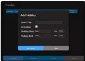
Holiday Setup Event
Click the [Holiday] button on the scheduler settings screen and the screen will appear.
Add Holiday: You can set holidays in
Download: You can download the created holiday settings as an XML file.
Upload: You can upload the downloaded holiday settings files
Add Holiday screen.
Click the [Add Holiday] button and the screen will appear.
Enter the holiday title to be set.
Set up the date and time to start and end the broadcast.
must be checked to operate the holiday settings.
Click the [Add Holiday] button when the setting is complete.
Set holiday settings are displayed on the scheduler.
You can change or delete set holidays.
If you set the date and time to start as 2021-01-01, 08:00 and the date and time to end as 2021-01-02, 23:00, the scheduled broadcast will be suspended from 8:00 on January 1st to 23:00 on January 2nd.
MAINTENANCE
Failover History Management
The failure history for the product can be input and managed.
On the Home screen, click → .
If you click the [Search] button, you can search the results by date.
Click the [Delete] button to delete the selected fault history.
Lists of Failure History: Shows the entire history of registered failures.
Register After inputting fixes and status of the failure history, they can be registered.
Date: Only the today's date can be entered as an input, and the date cannot be changed.
Device Name: Enter the name of the device where a failure occurred. (Max. 20 characters)
Status: Enter the failure status. (Max. 20 characters)
Fallover Contents: Enter the processing details. (Max. 70 characters)
Registerer: Enter the name of the user. (Max. 20 characters)
Receive Lists: The registered history of actions for malfunctions can be downloaded in the "csv" file format.
As the history of actions for malfunction will be deleted when the product's system is initialized, please download it in advance.
■ Every input field must be filled in.
■ Special characters (‘, ‘) cannot be input in the input field.
- Locate a mouse pointer on a failure history item to see all the registered details.
View Log
You can check logs generated in the product.
The log items are different for each product, and they are recorded when the log operation occurs.
On the Home screen, click → .
The action log history for the device is shown by item.
The Log menu will appear on the View Log when its function is activated.
If you click the [Receive Logs] button, a file can be downloaded in HTML format. Check HTML files via Google Chrome.
As the log information will be deleted when the product's system is initialized, please download it in advance.
If you click the [Delete Logs] button, all logs displayed on the screen will be deleted.
The Output Unit, Auto Update, Update Period, and Scroll Mode can be set.
If you activate , logs will be displayed in accordance with the
If you auto select , the screen will be moved downward to show recent logs.
Press the [Top/Bottom] button to view the upper and lower logs.
using speaker mode
If you select to in the speaker's , you can perform scheduled broadcasting, BGM and TTS broadcasting using the speaker alone. Also, because it is set up as device register and source (audio input device), zone (audio output device) in the mode speaker or server (SPA-S1000), it can perform several broadcast operations.
You can move to the website that supports functions below by selecting for the of the Speaker.
Name Function Description
1
Home Goes to the Home screen.
Operation Setting
Various operations are available, such as Contact, Broadcast Annual Scheduling, and SIP.
Maintenance Logs generated in the product can be checked.
Environment Setting The System Management, Network, Time, Device Information, etc. can be set.
2
Product Model Name Displays the device's model name.
3
Product Information
The IP address, product name, product location, and firmware version are displayed.
4
Connected Account/Login Shows a connected account and its login status.
5
Time Information
The connection time to the web page menu, product cumulative operating time, and product time will be displayed.
6
Language Shows language options supported on the website. (Korean, English supported)
7
Go to the Official Website
If you click, the screen will move to the Hanwha Vision Official Website.
The optimal monitor resolution is 1920x1080.
38_ using speaker mode
OPERATION SETTINGS
You can set up the CP function, broadcast audio (BGM, TTS, CHIME), DSP (speaker, built-in microphone volume), scheduled broadcast and SIP (VoIP phone voice transmission).
Contact Closure Settings
On the Home screen, click → .
If you select the and tab, the status information will be displayed.
When the input or output device is running,
When the input or output device is not running,
For Contact Closure Input, a real input signal has to occur to change the status information. Whether the Contact Closure Output is operating or not can be checked manually by clicking its status information on the screen.
Contact Closure Input
By connecting to the Contact Closure Output of an external device, such as an electrical switch, smoke detector, or motion detector, it can be used as the Contact Closure Input of the speaker.
You can perform a warning broadcast through the speaker when detecting a motion by connecting the motion detector to the contact closure signal.
When the contact closure signal is entered, the BGM audio, which is set up in the "Event & Preset" function in advance, will be automatically broadcasted.
Contact Closure Output
A Contact Closure Output can send signals to the broadcast system or send a warning signal to an external device, such as a lightbar, by connecting to it.
You can output the command for the contact closure of speakers by simply pressing the CP buttons on
- You cannot use contact closure input with a speaker by itself
For the contact closure settings and operation method, refer to on pages 32 and 33.
BGM Play
You can register an audio file for broadcasting.
On the Home screen, click → .
Click the [ ] button to select the PC folder containing the sound source files to be uploaded.
The internal storage has an available capacity of up to 1GBytes, and there are no restrictions on the size and number of sound files within the capacity.
■ Supported source types: WAV (16bit), MP3
- Supported MP3 bit rates: Only MP3 (mono/stereo) in the range of 64kbps to 320kbps
■ Supported WAV Sampling Rate: 16Khz, 32Khz, 44.1Khz, 48Khz
■ PCM-type WAV files without header information cannot be used.
- If the sound source file name contains special characters, it may not be uploaded. Please change the file name (remove special characters) and upload again.
- Please delete audio files which cannot be played as they will be displayed as "unable to use" on the screen if they are uploaded or played.
Click the [Upload] button after selecting source files to upload.
You can select External Storage (SD) and upload if the product has a microSD card.
The available capacity of the internal and external storage is displayed and an upload unavailable window appears when they are smaller than the source files to be uploaded.
Insert or remove the microSD card while the product is turned off.
Be sure to format the microSD card in FAT32 (file system) before inserting it into the speaker.
■ NTFS and exFAT (file systems) are not supported.
- A microSD card capacity of up to 32 GB is supported (SDHC, MLC. Class 10 or higher).
■ We recommend Sandisk and Transcend products.
- Compatibility by manufacturer and product type may vary.
Uploaded source files are displayed on the right
Various information is provided, and repeated playback of audio (up to 99 times) is also possible.
A microSD card icon is displayed with the file name for the files saved to external storage (SD)
If the source file name is duplicated, it is overwritten.
You can download or delete uploaded source files.
- When you try to download two or more audio resources, the pop-up window granting permission will appear.
If you have pressed the permission-block button, click the top right button on the web page (shown with the icon) to select .
Play/pause, stop, previous song/next song (select multiple sound sources), repeat are possible. When audio is played, its title will be shown as it scrolls across the screen.
If the speaker's power is turned off and on while the audio is played or is in a state of being paused by pressing the PAUSE button, the audio will be played from the beginning automatically. In the state where playback has stopped from pressing the STOP button, it does not play automatically.
7. The output volume is reflected only to . If you run mute from the →
using speaker mode
BGM Streaming
This is a function to directly transmit and play sounds that have been uploaded to BGM Play to speakers registered in through the network.
To connect, you must go to for the speakers and enter the same IP address and port number entered in for Unicast or Multicast.
You can send audio to another speaker through the setup.
You can receive audio from another speaker through the setup.
As it uses audio uploaded to BGM Play, you cannot upload or delete audio on BGM Streaming.
On the Home screen, click → .
The and screens are displayed when selecting the initial menu.
Broadcast Server Settings
• Communication Method: Supports TCP/IP
- Transmission Method: Select between Unicast and Multicast. You can select both Unicast and Multicast.
- Unicast can transfer the audio up to 1:20 speakers while Multicast can transfer audio up to 1:256 speakers.
- You have to select the transmission method in consideration of the network environment being used.
• Operation Information: Sets the port where the server operates The basic streaming port is set as 5455.
- Click the [Apply] button to save the settings and move to the Broadcast Server screen.
Broadcast Server Operation Information
When you click the [Apply] button on , the server begins operation, and you will be moved to the following screen which shows the source file list, playback information & server settings, and the client connection list.
In the →
Click → .
Click the [Start], [Stop] buttons to select whether to operate the broadcast server.
Click the [Settings] button to move to the screen.
You can check the information of source files on the Source File List.
Click the number of the source file lists to play through the PC speaker.
For audio files that have had their right checkboxes checked on the Source File List, you can play audio files using the [ ] buttons with other speakers in addition to the source speaker.
You need to enter the same IP addresses and port numbers that are set as Unicast or Multicast from the in the of the source speakers or other speakers.
Communication information and operation information are displayed in .
displays the information of other connected speakers (Activated, Deactivated status) only if the speaker transmission method is set to Unicast.
If you set the speaker transmission method to Multicast, the information of other connected speakers will not be displayed, but the sound source play function will run.
Broadcast Client Settings
• Communication Method: Supports TCP/IP
• Transmission Method: Select the same method as the broadcast server to connect between Unicast and Multicast
- Unicast is a 1:N server-client structure. (Maximum 1:20)
- Multicast can be broadcast to all clients in the channel via the channel communication method. (Maximum 1:256)
- Set IP Address and Port. Enter the IP address and port of the server to be connected.
- Click the [Apply] button to save the settings and move to the Broadcast Client screen.
Broadcast Client Operation Information
When you click the [Apply] button in the , the client operation starts, and you will be moved to the screen below which shows client settings, play, and server and operation information.
Click = .
Click the [Start], [Stop] buttons to select whether to operate the Broadcast Client.
Click the [Settings] button to move to the screen.
Communication Information and Play Information are displayed on . When the source files are played through mode or mode, the MP3 Encoding (MP3, WAV) or PCM Encoding (TTS) information value will be displayed on the Play Information.
Server Information connected to Broadcast Client is displayed on
If the source files are played using mode or mode, it is displayed on the Level Meter of and you can control the volume.
If you broadcast with the source speaker selected from the →
If you broadcast with the source speaker selected from the menu of the speaker, the IP address and port number of the source speaker are automatically reflected in the client's server information.
- When you operate the broadcasting system with a speaker or server (SPA-S1000), do not separately set the transmission method and operation information of or .
using speaker mode
Chime File Management
If you broadcast TTS audio in the →
On the Home screen, click → .
Click the [ ] button to select the PC folder containing the Chime files to be uploaded.
■ Supported source types: WAV (8bit), MP3
■ Supported MP3 bit rates: Only MP3 (mono/stereo) in the range of 64kbps to 320kbps
■ Supported WAV Sampling Rate: 16Khz, 32Khz, 44.1Khz, 48Khz
- PCM-type WAV files without header information cannot be used.
- If the sound source file name contains special characters, it may not be uploaded.
Please change the file name (remove special characters) and upload again.
- Please delete audio files which cannot be played as they will be displayed as "unable to use" on the screen if they are uploaded or played.
Click the [Upload] button after selecting source files to upload.
Chime files can be uploaded between the internal storage and external storage (SD) and share the Available Capacity with BGM and TTS files.
Up to 10 files can be uploaded, and uploaded files up to 10 seconds long can be saved.
Uploaded Chime files are displayed on on the right side. Click the number of the source file to play through the PC speaker.
A microSD card icon is displayed with the file name for the files saved to external storage (SD)
You can download or delete uploaded Chime files.
Chime files can be selected as either a start or stop the chime on the in → .
TTS File Management
You can convert the text into a human voice.
If you adjust the intonation, speed, etc., for the input language, a more natural voice output can be generated.
On the Home screen, click = .
Enter
• The title you enter will be used as the file name.
- Select language: English (United States, United Kingdom), German, Spanish, French, and Russian are supported.
- Select gender: You can select a male or female voice.
- TTS input language and the language the speaker has chosen should be the same to play TTS-converted audio normally.
If they are not the same, there will be a pop-up window that says
42_ using speaker mode
When you enter a special character, please refer to the following content.
In the TTS input window, you cannot enter & or '.
You can enter ^ () _ | "", but they are not converted to audio.
If @ # \$ % = \ / * are located alone or in the middle of sentence or numbers, they will be converted to audio.
Depending on the supported language or sentence structure, a special character may not be converted to audio.
Set to be played after the start and end of the TTS broadcast.
- Select Start Chime: Select the file to be used as a start chime from the list.
- Select End Chime: Select the file to be used as an end chime from the list.
Select .
- Pitch: You can set the pitch of the TTS voice.
• Speed: You can set the speed of the TTS broadcast.
• Volume: You can set the default volume of the TTS voice.
Even when another audio source is broadcasting, it is broadcast with the set TTS volume.
- Delayed between sentences: You can set the pause time between sentences. The same delayed time is applied to the special characters ? and !.
- Delayed between comma: You can set the delayed time for the next sentence after the comma.
Click the [Preview] button to play the created TTS files (except for chimes) through the PC speaker.
Click the [Save] button to save the set TTS files.
If you click the [Reset] button, set values for input information, and options are reset.
■ Only TTS files created directly from the website can be used.
- TTS files can be uploaded between the internal storage and external storage (SD) and share the Available Capacity with BGM and Chime files.
Click the number of the TTS file to play through the PC speaker.
Delete: Click the [icon] icon after selecting TTS files.
DSP Settings
You can control the speaker's output volume and the microphone's input volume.
On the Home screen, click = .
Set .
- DISABLED: The input volume of the internal microphone of the speaker is turned off.
- CONDENSER MIC: It controls the Gain(Volume) value of the internal microphone of the speaker. function is available for the audio module after connecting the external microphone.
If it is set up as , the speaker's audio output status is visualized as audio signals and displayed in →
Set
Volume: Controls the output volume of the speaker. (input value 0\~100, increments of 1.0)
Even if you adjust the speaker's Output volume, it is not reflected to the output device volume in → of the controller device.
Mute: Mutes the output volume of the speaker.
using speaker mode
For the IP audio module (SPA-D1000), the Equalizer menu is provided so that its sound can be properly adjusted according to the characteristics of the connected analog speaker.
The Equalizer menu is not provided as the DSP optimal value is reflected for each speaker model.
- Parametric Equalizer (PEQ)
- Flat: Resets the set PEO value.
- Type: Provides 8-band peaking type.
- Gain: Controls the output value for each band. (input value -12\~+12, increments of 1.0)
- FREQ: The frequency band values, which are provided for each BAND, are displayed.
- PRESET: Saves or loads PEQ set values to apply them.
44_ using speaker mode
Annual Scheduler
A broadcast reservation can be set.
Broadcast sound sources can be broadcast through the speaker alone by directly entering sound files (mp3, wave) registered in BGM Play or TTS phrases.
It is possible to create daily, weekly, monthly, and annual loop schedules, and it will not broadcast on days set as holidays.
On the Home screen, click = .
- Registered schedules can be viewed by month/week/day/year.
The scheduler's additional functions can be used.
- Stop: The currently playing broadcast will stop.
• Holiday: Holidays can be set.
- Download: Registered schedules can be downloaded as "xml" files.
- Upload: A downloaded schedule can be uploaded to other speakers.
If there are both weekday and holiday schedules, the holiday schedule will not be reflected even if you upload a downloaded file.
For holiday schedules, use the download and upload functions of the menu.
- Copy: Schedules for each month can be copied.
When the Copy Settings window appears, click the [Copy] button.
The selected year automatically resets to the fifth year from the pertinent year.
• : Renews a schedule list.
Schedules registered on each date are shown, and if you select a date where you want to create a schedule, the schedule setting screen will appear.
■ If you register 4 or more schedules for one day, it will be indicated as <+2>.
Schedule Setting Screen
It is a screen where you can set schedules.
If there are duplicate broadcast schedules (BGM, TTS audio source) at the same time, the schedule which is registered later will be run.
If there is a schedule where one time period overlaps with another, the earlier one will stop upon the beginning of the later one while running the later one's broadcast schedule.
Name: Input a name for a schedule.
Date & Time: Select a date when a schedule is to be taken place.
Select or input a time when a schedule is set to take place.
If you click the [Now+1(min)] button, the start time of the schedule is set to a minute after the current time.
If it is set to Date (2021-01-01 / 2021-01-01), Time (10:00 / 09:00), an input error window (time error) pops up.
(2021-01-02 / 2021-01-01). Date (09:00 / 10:00), an input error window (date error) pops up.
If it is set to Date
Repeat: Select a day, a period, etc, you want to set.
Select Day: During the set dates, it runs only on selected days of the week. If you select days of the week, and are deactivated.
Once: Even during the set period of the dates, it runs only once on the first date.
If you set it to the date (2021-01-01 / 2021-01-02), time (09:00 / 09:10), , the broadcast schedule is set up for 10 minutes from 9:00 to 9:10 on January 1st.
- If you set it to the date (2021-01-01 / 2021-01-02), time (23:00 / 01:00), , the broadcast schedule is set up continuously from 23:00 on January 1st to 1:00 on January 2nd.
- Everyday: During the set period of dates, it runs repeatedly every day.
If you set the date (2021-01-01 / 2021-01-02), time (09:00 / 09:10), , the broadcast schedule is set up for 10 minutes from 9:00 to 9:10 from January 1st until January 2nd.
- If you set the date (2021-01-01 / 2021-01-02), time (23:00 / 01:00). , the broadcast schedule is set up twice from 23:00 on January 1st until 1:00 on January 2nd and from 23:00 on January 2nd until 01:00 on January 3rd.
using speaker mode
- Repeat Option (Extension): Sets the set schedule to repeat on a weekly, monthly, or yearly basis.
- If you set up the or function, check that the set schedule is accurate on the [Weekly Calendar]. [Daily Calendar] screen.
When setting the , the schedule period should not exceed one week for , 28 days for , or 365 days for .
■ For , a schedule is set every week from the selected day of the week.
For and , If you select a specific day, the schedule is set on the specific date for every month or year.
If you specify a date range in or and select days of the week in [Everyday], the schedule is set only for those days of the week which exist within the date range.
You can delete a specific day from the schedule date range or delete all recurring events.
Source: The , IP address are displayed as <127.0.0.1>.
Zone: Not displayed in mode.
Source sound: Select an audio source type to be broadcast from schedules.
• MP3 Play: Displays a list of audio sources registered in BGM Play.
The length of the selected audio will automatically be reflected to the end time of and displayed as being deactivated.
If you input the , an audio source will play repeatedly and automatically displayed at the end time.
If you uncheck , you can directly enter the end time so that it is broadcast only at the time you want.
The playing order of the audio can be changed using the [ ] on for each file.
If the date is 2021-01-01 / 2021-01-01, the time starts at 23:55, and the length of the selected audio source is 10 minutes, the end date and end time will be set to 2021-01-02 and 24:05 automatically.
If it is set to , the broadcast schedule is set from 23:55 on January 1st to 0:05 on January 2nd continuously. If it is set to , the continuous broadcast schedule is set twice from 23:55 on January 1st to 0:05 on January 2nd and from 23:55 on January 2nd to 0:05 on January 3rd.
- TTS: Enter sentences with the language to be used in the and select the language and gender in Select Speaker.
- Select language: English (United States, United Kingdom), German, Spanish, French, and Russian are supported.
- Select gender: You can select a male or female voice.
- TTS input language and the language the speaker has chosen should be the same to play TTS-converted audio normally.
If they are not the same, there will be a pop-up window that says
- When you enter a special character, please refer to the following content.
In the TTS input window, you cannot enter & or '.
You can enter ^() _ I "", but they are not converted to audio.
If @#\$ % = \ / * are located alone or in the middle of sentence or numbers, they will be converted to audio.
Depending on the supported language or sentence structure, a special character may not be converted to audio.
ETC.: You can set other settings of the schedule.
Priority: A lower number has a higher priority. If the priority is "1501", it will be on air prior to any other broadcasts.
As the priority of a general audio broadcast is set to 3000 by default, the priority of the annual scheduler is recommended to be set at a value lower than 3000. (The initial value is 3000, the input value is 1501 - 9999)
Volume: You can set the volume when the schedule is operated. (Initial value 70, input value 0\~100) Output volume is reflected only to .
Date Format: You can select the date format displayed on the scheduler.
Title Color: You can select the color displayed on the scheduler.
If the controller mode speaker or source speaker is rebooted during scheduled broadcasting, the first sound source among the selected sound sources is played again, and it stops when it reaches the scheduled end time.
If the zone speaker is rebooted during scheduled broadcasting, the sound source is skipped and plays, and then stops when it reaches the scheduled end time.
Holiday Setup Event
Click the [Holiday] button on the scheduler settings screen and the screen will appear.
Add Holiday: You can set holidays in .
Download: You can download the created holiday settings as an XML file.
Upload: You can upload the downloaded holiday settings files
Add Holiday screen.
Click the [Add Holiday] button and the screen will appear.
Enter the holiday title to be set.
Set up the date and time to start and end the broadcast.
must be checked to operate the holiday settings.
Click the [Add Holiday] button when the setting is complete.
Set holiday settings are displayed on the scheduler.
You can change or delete set holidays.
- If you set the date and time to start as 2021-01-01, 08:00 and the date and time to end as 2021-01-02, 23:00, the scheduled broadcast will be suspended from 8:00 on January 1st to 23:00 on January 2nd.
SIP Management
When it is connected to the VoIP phone which uses the standard SIP protocol and IP PBX server, the voice on the VoIP phone can be played on the speaker.
The SIP function has been verified in an IP PBX server (Asterisk) and VoIP phone (Grandstream, Yealink, Cisco) environment.
The SIP function has been verified in an IP PBX server (Grandstream) and VoIP phone (Grandstream) environment.
SIP Account
Register the account and IP PBX information in .
User ID: ID of SIP users (account in the IP PBX).
Name: Names that users enter for easy identification.
Transport Mode: UDP mode is provided using the VoIP packet transmission method.
• Media Encryption: No encryption is used.
Password: Enter the password provided by IP PBX.
Domain: Enter the address of IP PBX.
Authentication ID: Enter the authentication ID provided by IP PBX. (It may not be used depending on the type of the IP PBX.)
Display name: It is the name which can be displayed on the receiver side. (It may not be used depending on the type of the IP PBX.)
Registrar: Enter the Registrar Server address, if the account is properly registered with Registrar, authentication is attempted regularly.
When you [save] , the registered information is displayed on the .
On the , you can select and modify the account.
Set whether to use the account as the default account or not.
When you check the account's [Default] on the , it will be sent from/received to that account.
The account's [Status] is activated and [detailed information of the status] is also changed from Idle to
Registered, and it is displayed as Online Devices in the IP PBX web page's Extensions menu. When you disable [Default], it is changed to Unregistered, and it is also displayed as Offline Devices in IP PBX.
using speaker mode
If you dial on your VoIP phone and speak, it will be received by and played on the speaker. The of the account will display as "Running, Conversation," and if you hang up the phone, it will change to "Disconnected." If you refresh the web screen, the status will be converted to "Registered" and maintained.
is provided as a default, and it can be used in both and speakers.
For , playing audio is possible when the account linked with the IP PBX server is additionally registered or when there is only the VoIP phone without being linked to the IP PBX server. For example, if it is sent from the VoIP phone on the same network to sip:99@192.168.1.99, it is connected to the SIP of the local host.
For the speaker, its volume can be controlled in the - -
- For the speaker, its volume can be controlled in the → →
SIP Settings
Enter items.
- Registration Interval: Enter the SIP registration period. (Default: 3600)
Enter items.
SIP Port: Set up the port to operate SIP communication. (Default: 5060)
• RTP Port: Set the RTP port. (Default: 35000)
Enter items.
Max Call Duration: Set the waiting time when a call ends abnormally.
information can be initialized/saved.
48_ using speaker mode
MAINTENANCE
View Log
You can check logs generated in the product.
The log items are different for each product, and they are recorded when the log operation occurs.
On the Home screen, click → .
The action log history for the device is shown by item.
Log Menu appears on View Log when its function is activated.
If you click the [Receive Logs] button, a file can be downloaded in HTML format. Check HTML files via Google Chrome.
- As the log information will be deleted when the product's system is initialized, please download it in advance.
If you click the [Delete Logs] button, all logs displayed on the screen will be deleted.
Output Unit, Auto Update, Update Period, and Scroll Mode can be set.
If you activate , logs will be displayed according to the .
If you auto-select , the screen will be moved downward to show recent logs.
Press the [Top/Bottom] button to view the upper and lower logs.
CE
Any changes or modifications in construction of this device which are not expressly approved by the party responsible for compliance could void the user's authority to operate the equipment.
This device complies with part 15 of the FCC Rules. Operation is subject to the following two conditions: (1) This device may not cause harmful interference, and (2) this device must accept any interference received, including interference that may cause undesired operation.
This equipment has been tested and found to comply with the limits for a Class A digital device, pursuant to part 15 of the FCC Rules. These limits are designed to provide reasonable protection against harmful interference when the equipment is operated in a commercial environment. This equipment generates, uses, and can radiate radio frequency energy and, if not installed and used in accordance with the instruction manual, may cause harmful interference to radio communications. Operation of this equipment in a residential area is likely to cause harmful interference in which case the user will be required to correct the interference at his own expense.
Hanwha Vision cares for the environment at all product manufacturing stages, and is taking measures to provide customers with more environmentally friendly products.
The Eco mark represents Hanwha Vision's devotion to creating environmentally friendly products, and indicates that the product satisfies the EU RoHS Directive.
Correct Disposal of This Product (Waste Electrical & Electronic Equipment)
(Applicable in the European Union and other European countries with separate collection systems)
This marking on the product, accessories or literature indicates that the product and its electronic accessories (e.g. charger, headset, USB cable) should not be disposed of with other household waste at the end of their working life. To prevent possible harm to the environment or human health from uncontrolled waste disposal, please separate these items from other types of waste and recycle them responsibly to promote the sustainable reuse of material resources.
Household users should contact either the retailer where they purchased this product, or their local government office, for details of where and how they can take these items for environmentally safe recycling.
Business users should contact their supplier and check the terms and conditions of the purchase contract. This product and its electronic accessories should not be mixed with other commercial wastes for disposal.
Correct disposal of batteries in this product
(Applicable in the European Union and other European countries with separate battery return systems.)
This marking on the battery, manual or packaging indicates that the batteries in this product should not be disposed of with other household waste at the end of their working life. Where marked, the chemical symbols Hg, Cd or Pb indicate that the battery contains mercury: cadmium or lead above the reference levels in EC Directive 2006/66. If batteries are not properly disposed of, these substances can cause harm to human health or the environment.
To protect natural resources and to promote material reuse, please separate batteries from other types of waste and recycle them through your local, free battery return system.
Hanwha
Vision
Other manuals Hanwha
Discover other manuals and user guides for the brand Hanwha
💬 Hi! I'm your manual assistant.I know your Hanwha SPA-H100B.
How can I help you? (use, settings, error codes, maintenance, explaining a step from the manual, etc.)💡 Examples :
• How do I use it ?
• Error code E3 ?
• How do I clean it ?


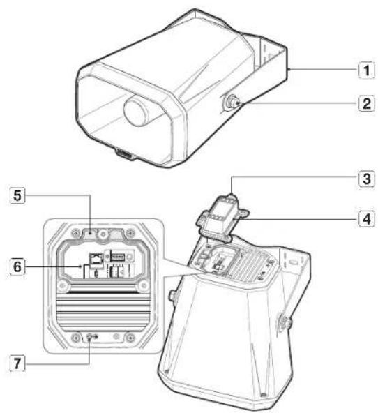

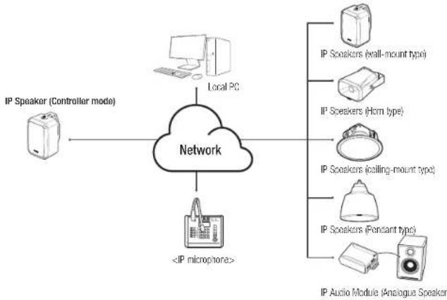


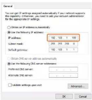


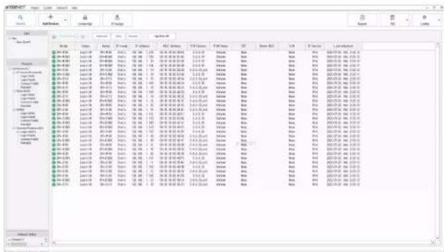

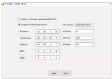
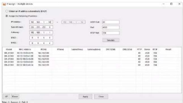




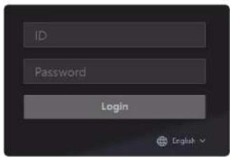


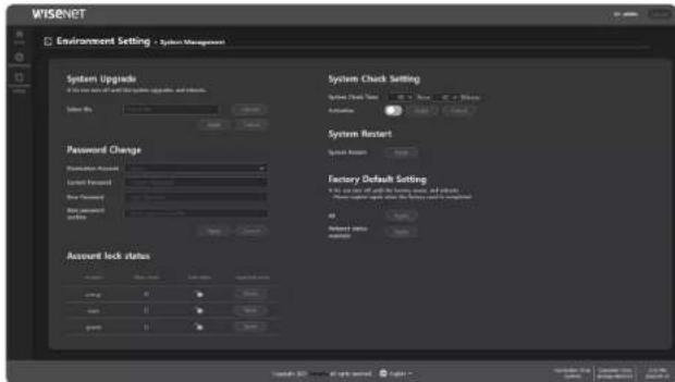

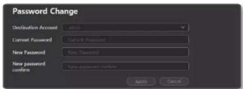
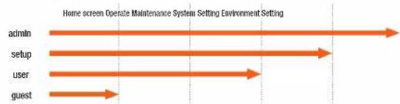


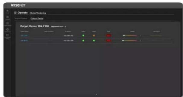
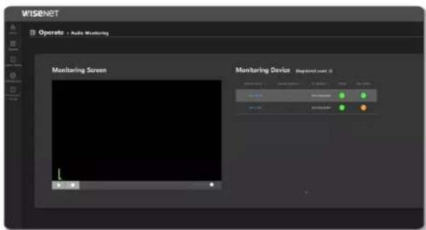


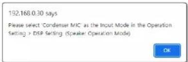

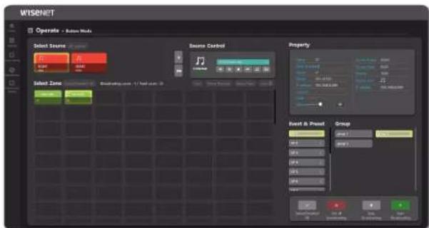

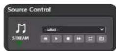


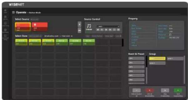


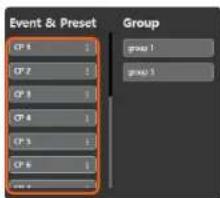

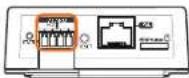





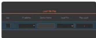




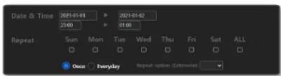
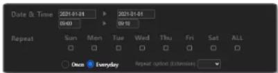
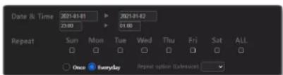
 2. [05.08](music2.mp3) Number of repeats 1 Source full time [PlayBack]](/content/2026/05/938554/images/9f2e61f2a1269ac4c71949096d08a13cfe9615ecaa93a562cfb209dd514f32a5.jpg)


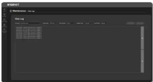


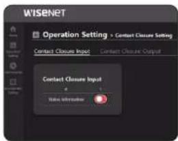
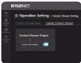


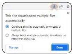
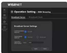


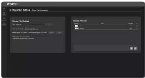
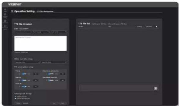





![Date & Time 2021-01-01 2021-01-02 22:56 Repeat Sun Mon Tue Wed Thu Fri Sat ALL Once Everyday Repeat option (detection) Source 1 8081 IP Address : 152.168.8264 Zone F1 F3 Select All Source sound MP3 PMy 1. [84.7] music3.mp3 [85.0] music2.mp3 Number of repeats 5 Source Full-line playback](/content/2026/05/938554/images/1578af5649b3e5eff0611a074b5146c3a145c38b5c5eb996d682633f5d95b10a.jpg)