
ScanNCut SDX330D - Paper Cutter BROTHER - Free user manual and instructions
Find the device manual for free ScanNCut SDX330D BROTHER in PDF.


| Product Type | Electronic Cutting Machine |
| Brand | Brother |
| Model | ScanNCut SDX330D |
| Cutting Method | Auto Blade (automatic blade adjustment) |
| Max Cutting Size | 12" x 24" (305 mm x 610 mm) |
| Max Cutting Speed | Up to 100 mm/s (adjustable) |
| Supported Materials | Paper, cardstock, vinyl, fabric, adhesive sheets, thin leather, craft foam |
| Blade Types | Standard (auto blade), Optional Rotary blade, Scoring blade, Pen holder |
| Display | 5.0 inch LCD touchscreen |
| Connectivity | USB 2.0, Wi-Fi (IEEE 802.11 b/g/n), Bluetooth (optional via adapter) |
| Built-in Scanner | Yes (12" x 24" scan area) |
| Registration Mark Scanning | Automatic, with built-in camera |
| Dimensions (W x D x H) | 22.8" x 8.7" x 12.2" (580 x 220 x 310 mm) |
| Weight | Approx. 22 lbs (10 kg) |
| Power Supply | AC 100-240V, 50/60Hz |
| Power Consumption | 60 W (operating), 1.5 W (standby) |
| Functions | Auto blade detection, multi-layer cutting, pattern matching, direct scan and cut |
| Maintenance | Clean blade after use; replace blade when dull; clean scanner glass regularly |
| Safety | Keep away from children; use on a stable, flat surface; unplug when not in use |
| Parts & Accessories | Included: Standard blade, cutting mat (12x24), pen holder, USB cable, power cord; Optional: rotary blade, scoring blade, various mats |
| Repairability | Repairs must be performed by Brother authorized service centers; user-replaceable parts: blade, cutting mat |
| General Information | Designed for crafters; includes ScanNCut Canvas software; multi-language support |
Frequently Asked Questions - ScanNCut SDX330D BROTHER
User questions about ScanNCut SDX330D BROTHER
0 question about this device. Answer the ones you know or ask your own.
Ask a new question about this device
Download the instructions for your Paper Cutter in PDF format for free! Find your manual ScanNCut SDX330D - BROTHER and take your electronic device back in hand. On this page are published all the documents necessary for the use of your device. ScanNCut SDX330D by BROTHER.
USER MANUAL ScanNCut SDX330D BROTHER
Product Code: 893-Z11
Be sure to read this document before using the machine.
Terms of Use
IMPORTANT-PLEASE READ CAREFULLY:
This Terms of Use (“Agreement”) is a legal agreement between Brother Industries, Ltd. (“Company”) and you that governs your use of any Software, installed on or made available by Company for use with sewing or craft products (“Company Product”). The term of “Software” means any and all contents data, design data, data format, firmware of Company Product, and PC application or mobile device application.
By using the Software and Company Product, you shall be deemed to have agreed to be bound by the terms of this Agreement. If you do not agree to the terms of this Agreement, Company is unwilling to license the Software and you are not allowed to use the Software. Amendments and supplements to this Agreement may be attached to the Software.
An individual who accepts this Agreement on behalf of an entity represents to Company that he or she has the legal right to enter into a binding legal agreement for that entity.
Terms and Conditions
1 Grant of License.
1.1 Subject to this Agreement, Company hereby grants you a personal, non-exclusive, non-transferable and revocable license to use the Software only within the Company Produ
1.2 Your right to use of the Software is licensed and not sold, and solely for your use subject to this Agreement. Company or its suppliers retains all right, title, and interest relating to Software, including without limitation all intellectual property rights relating thereto.
2 Restrictions
2.1 Except as expressly set out in this Agreement or as required by any local law, you shall undertake:
2.1.1 not to disassemble, de-compile, reverse engineer, translate or otherwise attempt to learn the source code of the Software(including the data or contents created by using the Company Product or contents editing application software; hereinafter the same shall apply in this Clause 2.);
2.1.2 not to create derivative works based on the whole or any part of the Software;
2.1.3 not to distribute, provide or make available the Software in any form, in whole or in part to any person without prior written consent from Company;
2.1.4 not to copy the Software, except where such copying is incidental to normal use of the Software with Company Product or where it is necessary for the purpose of back-up or operational security;
2.1.5 not to transfer, rent, lease, sub-license, loan, translate, merge, adapt, vary, alter or modify, the whole or any part of the Software nor permit the Software or any part of it to be combined with, or become incorporated in, any other programs;
2.1.6 to include Company's copyright notice and this Agreement on all entire and partial copies of the Software; and
2.1.7 not to use the Software for any purpose (including, but not limited to, use with unauthorized sewing/craft products or software) other than as provided under Clause 1 of this Agreement.
TO THE EXTENT PERMISSIBLE BY APPLICABLE LAW, THIS SOFTWARE IS PROVIDED TO YOU "AS IS" WITHOUT WARRANTIES OR CONDITIONS OF ANY KIND, WHETHER ORAL OR WRITTEN, EXPRESS OR IMPLIED. COMPANY SPECIFICALLY DISCLAIMS ANY IMPLIED WARRANTIES OR CONDITIONS OF MERCHANTABILITY, SATISFACTORY QUALITY, NON-INFRINGEMENT AND/OR FITNESS FOR A PARTICULAR PURPOSE.
4 Limitation of liability
4.1 COMPANY SHALL NOT BE LIABLE TO YOU, ITS END-USERS OR ANY OTHER ENTITY FOR ANY LOSS OF PROFITS OR INCOME OR SAVINGS, LOSS OF DATA, INTERRUPTION OF USE, OR CONSEQUENTIAL, INCIDENTAL, SPECIAL, PUNITIVE OR INDIRECT DAMAGES INCURRED BY SUCH PARTY (WHETHER IN AN ACTION IN CONTRACT OR TORT), EVEN IF COMPANY HAS BEEN ADVISED OF THE POSSIBILITY OF SUCH DAMAGES, ARISING OUT OF OR RELATING TO THE SOFTWARE, SUPPORT SERVICE OR THIS AGREEMENT. THESE
LIMITATIONS SHALL APPLY TO THE MAXIMUM EXTENT ALLOWED BY APPLICABLE LAW NOTWITHSTANDING ANY FAILURE OF ESSENTIAL PURPOSE OF ANY LIMITED REMEDY.
4.2 NOTWITHSTANDING THE CLAUSE 3 OR 4.1 HEREOF, THIS AGREEMENT DOES NOT PURPORT TO EXCLUDE OR RESTRICT COMPANY'S LIABILITY FOR DEATH OR PERSONAL INJURY RESULTING FROM NEGLIGENCE OR LIMIT THE STATUTORY RIGHTS OF A CONSUMER.
5 T e r m i n a t i o n
5.1 Company shall have the right to terminate this Agreement at any time by providing a written notice to you if you commit a material breach of any terms of this Agreement and fail to immediately rectify such breach upon Company's request.
5.2 Upon termination for any reason all rights granted to you under this Agreement shall cease, you shall cease all activities authorized by this Agreement and you shall immediately delete or remove the Software from all computer equipment in your possession and delete or destroy all copies of the Software or its derivative works in your possession. In addition to the above, you shall delete contents or design data created by you from the Company Product in your possession.
6 Miscellaneous terms
6.1 You shall not export or re-export the Software or any copy or adaptation thereof in violation of any applicable laws or regulations.
6.2 You shall not assign all or any part of this Agreement to any third party or any interest therein, without prior written consent of Company. A change of control or reorganization of you pursuant to a merger, sale of assets or stock shall be deemed to be an assignment under this Agreement.
6.3 You agree that a breach of this Agreement will cause irreparable injury to Company for which monetary damages would not be an adequate remedy and Company shall be entitled to seek equitable relief in addition to any remedies it may have hereunder or at law without a bond, other security, or proof of damages.
6.4 If any provisions of this Agreement shall be declared or determined as void or unenforceable by a court of competent jurisdiction, such provisions shall be severable and independent from the other provisions of this Agreement and the validity of the other provisions and of the entire Agreement shall not be affected thereby.
6.5 This Agreement, together with all exhibits or other attachments referenced herein, constitutes the entire agreement between the parties on the subject matter hereof, and supersedes all proposals, oral and written, between the parties on this subject.
6.6 If Company fails to insist that you perform any of your obligations under this Agreement, or if Company does not enforce any rights against you, or if Company delay in doing so, that will not mean that Company have waived any rights against you and will not mean that you do not have to comply with those obligations. If Company does waive a default by you, Company will only do so in writing, and that will not mean that Company will automatically waive any later default by you.
6.7 This Agreement is governed by the laws of Japan and Japanese Courts shall have exclusive jurisdiction with respect to this Agreement except with regard to enforcement in which case the jurisdiction of the Japanese Courts shall be non-exclusive.
6.8 The Company may update this Agreement in the below cases: A) When the changes are made for the users' benefit, or B) When the updates to the Agreement are adequate, reasonable, and not contrary to the purposes of the Agreement. The Company will notify you and give you the opportunity to review any material changes or updates to the Agreement, by posting a notice on the Company's website or a website specified by the Company at least 30 days before the Agreement enters into effect. Once the updated Agreement is in effect, you will be bound by it if you continue to use the Software.
INTRODUCTION
Thank you for purchasing this machine.
Before using this machine or attempting any maintenance, carefully read the "IMPORTANT SAFETY INSTRUCTIONS" on the Product Safety Guide, and then read the Operation Manual for the correct operation of the various functions. In addition, after you have finished reading this manual, store it where it can quickly be accessed for future reference. Failure to follow these instructions may result in an increased risk of personal injury or damage to property, including through fire, electrical shock, burns or suffocation.
IMPORTANT NOTICE
● This machine is intended for household use.
●This machine is approved for use in the country of purchase only.
● Due to product quality improvements, the specifications or appearance of this machine may change without notice.
● The screens in this manual are for illustration purposes only and may differ from the actual screens.
●The contents of this document are subject to change without notice.
● The contents of this document may not be duplicated or reproduced, partially or in full, without permission.
- We assume no responsibility for damages arising from earthquakes, fire, other disasters, actions of third parties, the user's intentional or negligent operation, misuse or operation under other special conditions.
●For additional product information, visit our web site at www.brother.com
IMPORTANT SAFETY INSTRUCTIONS
Symbols Used in This Document
The following symbols are used in this document.
 | WARNING | Failure to observe instructions with this marking may result in fatal or critical injuries. |
 | CAUTION | Failure to observe instructions with this marking may result in serious injuries. |
CONTENTS
Terms of Use ...... i
INTRODUCTION 1
IMPORTANT NOTICE ...... 1
IMPORTANT SAFETY INSTRUCTIONS ..... 1
Symbols Used in This Document.... 1
FEATURES...... 4
Patterns ("Pattern" mode) 4
Scanning ("Scan" mode)...... 4
Transferring Data using the Wireless Network
Connection Function.... 5
1 GETTING STARTED......6
PARTS AND FUNCTIONS ...... 6
Unit Descriptions - Front...... 6
Unit Descriptions - Rear....7
Unit Descriptions - Operation Panel 7
Included Accessories....7
BEFORE USE 8
Placing the Machine....8
Removing the Packing Materials.... 8
Turning On/Off the Machine....8
Preparing for Feeding the Mat 9
Operation of LCD Panel 9
MACHINE SETTINGS 10
Settings Screen.... 10
Auto Shutdown.... 12
2 BASIC OPERATIONS......14
FIRST STEPS.... 14
Selecting the Mat and Blade Appropriate for the Material.... 14
Reference Table of Mat, Blade and Material Combinations .... 16
Attaching the Material to the Mat.... 19
Installing and Uninstalling the Holder.... 27
Test Cut (Trial Cut) 28
PATTERN CUTTING 32
Tutorial 1 - Cutting Patterns.... 32
Tutorial 2 - Cutting Advanced Patterns.... 35
Tutorial 3 - Adding a Weeding Box to a Pattern.... 40
PATTERN SELECTION 42
Selecting a Single Pattern.... 42
Selecting Multiple Patterns 42
3 ADVANCED OPERATIONS...44
CUTTING AND EDITING FUNCTIONS ..... 44
Pattern Editing Functions.... 44
Pattern Editing Functions - Multiple Patterns ..... 45
Mat Layout Screen.... 45
Layout Editing Functions.... 46
Object Editing Screen 47
Undoing an Operation.... 48
Grouping/Ungrouping Patterns.... 48
Welding (Merging the Outlines of Multiple Patterns) 50
Adding an Offset Line to the Pattern.... 51
Aligning Patterns 52
Auto Layout Functions 54
Scanning a Background Image 54
Character Input Functions.... 56
DRAWING FUNCTIONS ....58
Drawing 58
Cutting Around Drawings.... 59
Using Drawing Functions to Fill Patterns/Make Outlines Thicker 63
MEMORY FUNCTIONS ......65
Saving 65
Retrieve Data.... 66
Importing Designs 67
4 SCANNING FUNCTIONS ... 68
SCANNING FOR CUTTING (Direct Cut)..... 68
Tutorial 4 - Scanning and Cutting 68
Advanced Cutting Functions for "Direct Cut" ..... 72
CREATING CUTTING DATA (Scan to Cut
Data)....74
Tutorial 5 - Creating Cutting Data .... 74
Adjusting Image Detection Levels.... 80
SCANNING IMAGES (Scan to USB)......82
Notes on Scanning.... 82
Tutorial 6 - Scanning to USB 82
Selecting the Area to be Saved.... 84
Transferring an Image to CanvasWorkspace...... 84
5 WIRELESS NETWORK CONNECTION FUNCTION... 86
Machine Wireless Network Connection
Settings 86
Enable the Wireless Network Function 86
Set up the Wireless Network.... 86
Check the Wireless Network Setup/Status...... 89
Using the "Others" Menu 89
Register Machine Under
CanvasWorkspace....90
6 DATA TRANSFER FUNCTION... 93
Retrieving Data from Application .....93
Retrieve Transferred Patterns from
CanvasWorkspace (Using a Wireless Network)... 93
Retrieve Transferred Patterns from
CanvasWorkspace (Using a USB Cable) (compatible only with Windows) 94
Batch Download a Pattern Collection from
CanvasWorkspace (compatible only with the Web version).... 95
Retrieve Transferred Patterns from Artspira (Using a
Wireless Network) 96
My Connection Function 97
Retrieving Embroidery Data for Cutting
(Compatible Models Only) 98
Preparing .phc, .phx or .pes Files 98
Retrieving the Pattern to the Cutting Machine..... 98
Creating Appliqué Data.... 99
Creating Embroidering Line Data.... 99
7 APPENDIX......102
CONSUMABLES 102
Replacement Criteria.... 102
Replacing the Blade.... 102
CARE AND MAINTENANCE.... 104
Cleaning 104
Cleaning the Scanner Glass.... 106
Adjusting the Screen.... 107
Adjusting the Scanning/Cutting Position ..... 107
Adjusting the Position of the Feed Roller...... 109
TROUBLESHOOTING 110
How can I Find the Wireless Security Information
(Network Name (SSID) and
Network Password).... 114
ERROR MESSAGES 115
UPDATING THE SOFTWARE 120
Automatic Update Function 120
Update Procedure Using USB Flash Drive ..... 121
Update Procedure Using the Application
(CanvasWorkspace) 121
OPTIONAL ACCESSORIES 123
PRODUCT SPECIFICATIONS 124
INDEX 125
Patterns ("Pattern" mode)
Select a pattern and edit it to create your own design. By simply loading craft paper or fabric, you can quickly create precision paper and fabric cutouts.
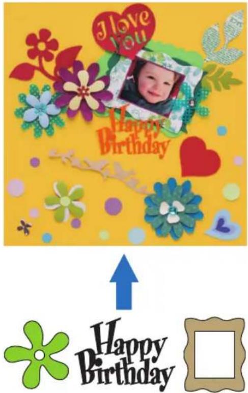
The editing functions of ScanNCut DX will allow you to easily edit the built-in patterns to create your own design.
Scanning ("Scan" mode)
Scan an illustration, photo or your own drawing to create personalized cut designs. The design can then be cut out or saved as data.
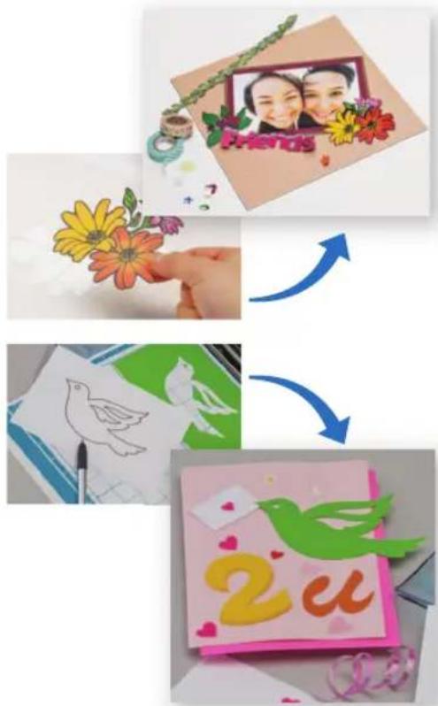
Without your PC or mobile device, you can scan your choice of pattern, use/edit the scanned design, and save the pattern for later use.
![graph TD A["Select a pattern.<br>"Tutorial 1 - Cutting Patterns"<br>on page 32<br>"Tutorial 2 - Cutting<br>Advanced Patterns" on<br>page 35"] --> B["Home screen"] B --> C["Scan an image.<br>"Tutorial 4 - Scanning and<br>Cutting" on page 68<br>"Tutorial 5 - Creating…](/content/2026/05/937368/images/79ac2b6e37360897d4e89a6a6f17b7d9af7cc41ac51336fd2a4d3ca2e362bd11.jpg)
Transferring Data using the Wireless Network Connection Function
This machine is equipped with a wireless network connection function. With this function, patterns edited in the dedicated application CanvasWorkspace or patterns data in Artspira can be transferred to the machine, or pattern data can be shared with Brother embroidery machines (*) via a wireless network connection. It is also possible to download software directly to the machine. Refer to the following to use the wireless network function.
* Compatible models only. For details on compatible models, check http://s.brother/cnxaa/.
![graph TD A["CanvasWorkspace"] --> B["Central Globe"] C["Artspira App"] --> B D["Device 1"] --> B E["Device 2"] --> B F["Device 3"] --> B G["Device 4"] --> B B --> H["Global"] style B fill:#f9f9f9,stroke:#333](/content/2026/05/937368/images/8b543854e0006a15f8dca9a3737213d123138ac41d324fe968a6ec3f62ab1a8f.jpg)
* Transferable data can only be sent one file at a time. If continuous transmission operations are performed from any device, only the most recent file can be recalled by the receiving device.
* Transferred data is sent and received via the shared Temporary Data Pocket. (Excluding uploads to CanvasWorkspace)
1. Connecting to a wireless network:
Touch or in the home screen to specify the wireless network connection settings. For the connection procedure, refer to "WIRELESS NETWORK CONNECTION FUNCTION" on page 86.
2. Register machine under CanvasWorkspace
In order to save or retrieve patterns using the wireless network function, your machine must first be registered with CanvasWorkspace.
Log into CanvasWorkspace (Web) to register your machine.
A CanvasWorkspace Login ID is required to use CanvasWorkspace.
If you do not already have a free account, create an account from [Member Registration].
For details, refer to "WIRELESS NETWORK CONNECTION FUNCTION" on page 86.
3. Retrieving/saving patterns:
Patterns can be downloaded or uploaded, without using a USB flash drive. For details, see "Saving" on page 65 and "Retrieve Data" on page 66.
CanvasWorkspace (Windows/Mac) is a PC based application that allows you to create and edit cutting or drawing pattern data to download to your cutting machine. This application allows you to edit the pattern data without an Internet connection.
You can download the application from the Brother support website (http://s.brother/cuoad/).
Also, by accessing CanvasWorkspace (Web) http://CanvasWorkspace.Brother.com, you can download Canvas Project recipes.
Artspira is a cloud based mobile app where you can transfer designs with WLAN connected machines.
For more information about the app, refer to the Artspira App Quick Guide. (https://s.brother/csyai/)
Chapter 1 GETTING STARTED
PARTS AND FUNCTIONS
Unit Descriptions - Front

①Operation Panel
Allows you to control the unit and specify settings with the LCD panel and operating buttons. The angle of the operation panel can be adjusted.
②Tool Tray
Stores accessories for easy access during use.
③Carriage
Moves the installed holder for cutting or drawing.
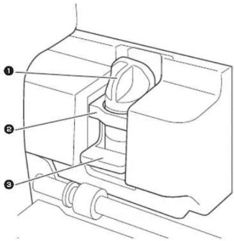
①Holder
Installs in the carriage to cut or draw on craft paper or fabric. Use the holder designed specifically for cutting or drawing.
②Holder Guide
The guide secures the holder.
③Holder Lock Lever
Releases the holder when the lever is raised. Locks the holder when the lever is lowered.
④Scanner Lever
Adjusted according to the operation being performed. For details, see "Preparing for Feeding the Mat" on page 9.
⑤Grips
Grasped when moving the machine.
⑥Feed Rollers
Should be adjusted on the right side when the optional roll feeder is used. For details, see "Adjusting the Position of the Feed Roller" on page 109.
⑦Shaft
Drives a feed roller on each end to feed the mat.
⑧Feeder Release Lever
Locks or releases the shaft when the optional roll feeder is used. For normal operations, set to the locked position. For details, see "Adjusting the Position of the Feed Roller" on page 109.
⑨Tool Holder
Holds accessories upright for easy access during use.
⑩Storage
Stores accessories.
⑪Front Tray Cover
Protects the feed rollers, carriage and holder. Open the cover while the machine is operating.
⑫Feed Slot
Feeds in the mat when it is loaded.
Unit Descriptions - Rear
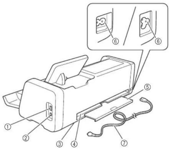
①USB Port (for a USB flash drive)
Allows a USB flash drive to be connected for saving and recalling data.
②USB Port (for a computer)
Allows a USB cable to be connected for saving and recalling data. For Computers and Operating Systems, see "Connecting Your Machine to the Computer" on page 94.
③Scanner Glass (inside of machine)
Can be maintained after the rear tray has been removed. For details, see "Cleaning the Scanner Glass" on page 106.
④Slot
Allows a mat to be fed back and forth during an operation. Do not place any objects near the slot that would prevent the mat from being fed out.
⑤Rear Tray
Supports the mat when it is fed out of the slot during operation. Be sure to pull out this tray before using the machine.
⑥AC Power Jack
⑦AC Power Cord
Unit Descriptions - Operation Panel
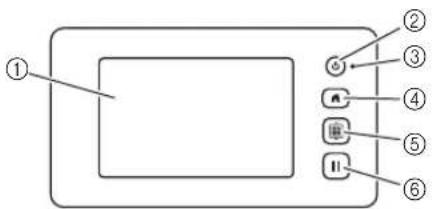
①LCD Panel
Displays operation screens, preview images of patterns and error messages.
②Power Button
Turns the machine on/off.
③Power Indicator
Lights up when the machine is turned on, and flashes when the machine enters the sleep mode (power-saving mode) or the machine's software is being updated.
④Home Button
Displays the home screen (starting screen for operating this machine).
⑤Feed Button
Feeds the loaded mat in to or out from the feed slot. Be sure to press this button to feed the mat when loading or unloading it.
⑥Pause/Stop Button
Stops or pauses operation being performed by the machine.
Included Accessories
For details on the included accessories, refer to the "Included Accessories" insertion.
Placing the Machine
Open the front cover, and check that the entire cover fits completely within the area of the desktop. When using a cutting mat, since the mat travels back and forth, make sure to keep enough space behind the machine.

①30 cm or more of open space
Removing the Packing Materials
Before turning on the machine, open the front tray cover, and then remove all shipping tapes (in front and back of the machine) and the cardboard shock-absorbing material.

①Shipping tape
②Cardboard shock-absorbing material

Note
- If the packing materials were removed after the machine was turned on, turn the machine off, then on again. Continuing to use the machine without restarting it may result in incorrect operation.
Turning On/Off the Machine
1 Connect the power cord to the machine.

①Power cord
2 Plug the power cord into an electrical outlet.
3 Press in the operation panel.
When the opening screen appears, touch anywhere on the display.

When the following message appears, touch the "OK" key.
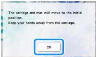
The home screen appears.


Memo
- LCD panels commonly have bright spots (permanently lit dots) and dark spots (unlit dots). It may cause some unexpected luminous spots to appear and tiny picture elements to be missed in the screen. Please note that this is not a sign of malfunction.
4 To turn off the machine, press ① the operation panel.
5 Unplug the power cord from the electrical outlet.
6 Disconnect the power cord from the machine.
Preparing for Feeding the Mat
1 Pull out the rear tray.
Before using the machine, be sure to pull out the rear tray.

2 Raise the scanner lever (on the left side of the machine) to "2".


Memo
- Before scanning thin material, set the lever to "1". Leaving the lever raised may result in blurred scans.
Operation of LCD Panel
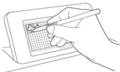
After the machine is turned on, the operation screens appear in the touch panel. To perform operations in the screens, use the included touch pen (stylus).
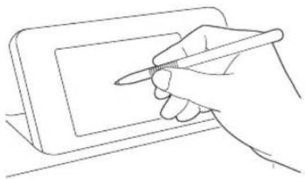

Note
- Never use a hard or pointed object, such as a mechanical pencil or screwdriver, to make a selection on the screens. Otherwise, damage to the machine may result.
Settings Screen
From the LCD panel, touch to select and adjust the settings for each function.
This section contains descriptions of the machine settings which will appear when is selected on the home screen.
■Group 1

①Touch to display the previous or next item.
* Swiping the touch pen (stylus) over the screen will also display a different screen.
②Touch to finish specifying settings.
Language
Select the display language. Touch this button, select the desired display language, and then touch the "OK" key.
Unit
Select either millimeters or inches as the displayed measurement units.
Cut Area
Specify the area for cutting/drawing according to the size of material to be used. Touch this button, and then touch and drag the area resizing keys to specify the area. When using a 12" × 24" (305 mm × 610 mm)
mat, touch to select a larger mat size, and
then specify the area size. When using a 12" × 12"
(305 mm × 305 mm) mat, touch . 12"× 12"
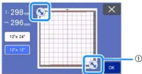
①Area resizing key (Using the touch pen (stylus), touch the key, and then drag it around the screen to specify the area.)

②Mat size key
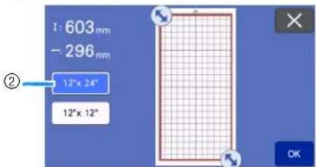
- Touch the "OK" key to apply the settings.
Touch to return to the previous screen without applying the settings.
Pattern Interval
Specify the spacing between patterns as well as white space around the edges of cutting area when patterns on the mat layout screen are automatically arranged. The larger the number setting, the further spacing between patterns.

Note
- Set the pattern interval to "3" or higher when lightweight fabric is attached to the mat with a high tack adhesive fabric support sheet.
- Set the pattern interval to "5" or higher when using the rotary auto blade.
Background
Adjust the contrast of a background image scanned with the background scanning function. For details, see "Scanning a Background Image" on page 54.
■Group 2

Cut Speed
Adjust the cutting speed.
Cut Pressure
Adjust the cutting pressure.
Cut Pressure (Manual Blade)
Specify the cutting pressure when the optional manual blade is used.
Cut Amount
Specify the cutting depth. Adjust the blade cut amount when a pattern with a sharp corner is cut from soft, thick material.
Half Cut
Select whether or not to make half-cuts. For details, see "Half Cut (Kiss Cut) Settings" on page 31.
Cut Pressure (Half Cut)
Specify the cutting pressure for half-cuts.
Cut Mode (Rotary Blade)
Select the cutting mode for when using the rotary auto blade holder. For details, refer to the instruction manual of the rotary auto blade kit.
Blade Adjustment Area
Select from 1/4, 2/4, 3/4 or whole cutting area to be used for blade adjustment. Before cutting out a pattern, this machine performs an automatic blade adjustment, which adjusts the direction of the blade outside of the adhesive area of the mat.

- With each press of the left or right arrow key, the size of the blade adjustment area changes by 1/4.

①1/4
②2/4
③3/4
④Entire area
Blade Adjustment Area (Rotary Blade)
Set the blade adjustment area for when using the rotary auto blade holder.
For details, refer to the instruction manual of the rotary auto blade kit.
Draw Speed
Adjust the drawing speed.
Draw Pressure
Adjust the drawing pressure. Adjustments to the drawing pressure will affect the finished product. Use the same material that the pattern will be drawn on to make the adjustments in advance. If the pressure is too high, the pen tip may be damaged. Adjust the pressure appropriately.
■Group 3

Seam Allowance
Specify the seam allowance. This is applied when drawing on fabric, then cutting it, for example, when making quilt pieces. For details, see “Cutting Around Drawings” on page 59.

Memo
- When multiple patterns are cut at the same time, the setting specified in this screen is applied to all patterns.
- If cutting line data saved with a different seam allowance is imported and used, the setting specified in this screen will have priority over the saved setting.
Fill
Select the design that will be used to fill patterns. For details, see "Using Drawing Functions to Fill Patterns/Make Outlines Thicker" on page 63.
Additional Line
With [Number of Additional Line], specify the number of lines to be added. With [Additional Line Spacing], specify the spacing of the lines to be added.

Memo
- For details for Fill and Additional Line setting, refer to "Using Drawing Functions to Fill Patterns/Make Outlines Thicker" on page 63.
■Group 4

Auto Shutdown
Specify the length of time for the auto shutdown function. The setting can be specified in 1-hour increments. For details, see “Auto Shutdown” on page 12.
Buzzer Sound
Select whether or not an operation sound is produced, for example, when a key is touched.
Opening Screen
Select whether the opening slide show is displayed after the machine is turned on. If the slide show is displayed, touch the screen to display the home screen.
Scanning/Cutting Position Adjustment
The scanning/cutting position can be adjusted. To adjust the position, touch this button to display the settings screen. For details, see "Adjusting the Scanning/Cutting Position" on page 107.
■Group 5
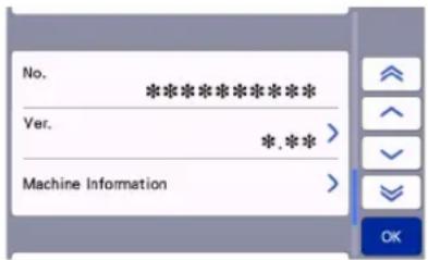
No.
Displays the number for this machine.
Ver.
Displays the version information for this software. Touch this button to update the machine's software. For details, see "UPDATING THE SOFTWARE" on page 120.
Machine Information
Touch this button, this page displays machine information.
■Group 6
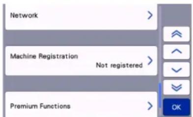
Network
Touch this button to set up a wireless network. For details, refer to "WIRELESS NETWORK CONNECTION FUNCTION" on page 86.

Memo
- The wireless network connection can also be set up by touching or in the home screen.
■Group 7
Machine Registration
Touch this button to specify settings for registering the machine with dedicated applications. These settings are necessary in order to transfer patterns via a wireless network connection. For details, refer to "WIRELESS NETWORK CONNECTION FUNCTION" on page 86.
■Group 8
Premium Functions
Activate optional accessories and specify settings for their functions.
■Group 9
Reset
Touch this button to display the reset menu. All the settings specified on the network and settings screens will be erased (reset to their defaults). To reset, press this key, and then turn the machine off, then on again.

①Network Reset
②Reset to Default

Memo
- When lending or transferring the machine to another person, or disposing the machine, please be sure to use "Reset to Default" menu to reset to their defaults to delete all the setting information and prevent third parties from accessing it.
Auto Shutdown
If the machine is not used for a specified length of time, it will automatically turn off. The length of time until the machine turns off can be specified in the settings screen.


If the machine is automatically turned off after you reach the mat layout screen, the stored information can be recalled when the machine is turned on again. Following the instructions in the message screen that appear when the machine is turned on again, touch the "OK" key to display the mat layout screen or touch the "Cancel" key to return to the home screen.
![graph TD A["OK to retrieve and resume previous memory?"] --> B["Add"] B --> C["Edit"] C --> D["Save"] D --> E["Scan"] E --> F["Retrieve Data"] E --> G["Test"]](/content/2026/05/937368/images/dddf5b8b7b3af05663659057aab072a3bef7fee8b46127e8b67de0be2347d628.jpg)
①Message screen
②Mat layout screen
③Home screen
If the machine is automatically turned off before you reach the mat layout screen, the home screen will be displayed when the machine is turned on again.
FIRST STEPS
The following procedures describe basic operations, from preparing the material to performing trial cutting.
- Selecting the Mat and Blade Appropriate for the Material .....P.14
- Reference Table of Mat, Blade and Material Combinations .....P.16
- Attaching the Material to the Mat.....P.19
- Installing and Uninstalling the Holder ......P.27
- Test Cut (Trial Cut) ......P.28
Selecting the Mat and Blade Appropriate for the Material
Refer to the following table and the "Reference Table of Mat, Blade and Material Combinations" on page 16 for the appropriate mat, sheet for fabric cutting, and blade according to the material to be used for cutting or drawing.
Depending on the machine model, some accessories listed in the chart may not be included. In that case, they must be purchased separately.
 Mat Mat | Sheet for fabric cutting Use one of the following sheets when cutting fabric. Use one of the following sheets when cutting fabric. | ||
| Standard tack adhesive mat | Our standard tack adhesive mat has a high adhesive strength for use with cutting.* Use the low tack adhesive mat with copy paper and smooth paper.Since the standard tack adhesive mat has a high adhesive strength, materials may remain stuck to the mat, causing the mat to become unusable. | Iron-on fabric appliqué contact sheet (white backing)(See page 20) | • Reinforces the fabric so that various patterns can be cut out.• Original texture may change because it remains attached to the back of fabric.* For use with the standard tack adhesive mat.* Do not place fabric backed with iron-on contact sheet directly onto a mat with high tack fabric support sheet. |
| Low tack adhesive mat | Low adhesive mat; suitable for copy paper and smooth paper. | High tack adhesive fabric support sheet(See page 24) | • For best results when cutting fabric, attach the high tack adhesive fabric support sheet to the standard tack adhesive mat in order to increase the strength of the adhesive.• Depending on the shape, the pattern may not be cleanly cut. |
| Fabric Mat Suitable | for cutting quilt pieces of thin cotton material (0.25 mm) and flannel (0.5 mm). No sheet for fabric cutting required. | ||
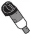 Auto Blade Holder (Blade) Auto Blade Holder (Blade) | |||
| Auto Blade (Black) | • Blade suitable for cutting a variety of materials such as paper, thick fabric, vinyl, or sponge sheets (0.1 mm to 3.0 mm thick, varies by material). | ||
| Thin Fabric Auto Blade (Beige) | • Blade suitable for quilt pieces without interlining (0.25 mm to 0.5 mm thick, varies by material). | ||
| Vinyl Auto Blade (Blue) | • Blade suitable for cutting fine patterns. Use it with vinyl sticker sheets and iron heat transfer sheets (0.1 mm to 1.0 mm thick, varies by material).• Use it installed to the vinyl auto blade holder (included with the vinyl auto blade kit). | ||
| Rotary Auto Blade (Turquoise) | • Blade that can minimize fraying and shape collapse of the cloth when peeling the material from the mat, and suitable for maintaining the texture of cloth while cutting (0.1 mm to 1.0 mm thick, varies by material).• Use it installed to the rotary auto blade holder (included with the rotary auto blade kit). | ||
Reference Table of Mat, Blade and Material Combinations
Use a mat and blade appropriate for the material, as referred to in this table. You can also check the latest reference table at http://s.brother/cfokb/.
Before using materials from your project, test attaching the material to check the adhesion to the mat. The optimal blade type will vary depending on the type or thickness of the material. Perform a test cut before cutting the material. For test cutting, refer to "Test Cut (Trial Cut)" on page 28. Depending on the material, the appropriate combination may differ from the table below. Always perform a test cut to be sure the material can be cut without a problem.
If a problem cannot be resolved, check the Q&A on the Brother support website (http://s.brother/cpoac/).

Note
- The blade holder included with this machine is an auto blade holder. It detects the thickness of the material and automatically adjusts the blade length.
- Thick or hard materials are automatically cut multiple times.
■Paper and Other Materials
| Material | Thickness | Mat (for ScanNCut DX) Auto Blade Holder (Blade) | |||
| Standard Tack Adhesive Mat | Low Tack Adhesive Mat | Auto Blade (Black) | Vinyl Auto Blade (Blue) | ||
| Printer paper 80 g/m2(0.1 mm) | ✕ | √ | √ | ||
| Scrapbook paper (thin) | 120 g/m2(0.15 mm) | √ | √ | ||
| Scrapbook paper (medium-thick) | 200 g/m2(0.25 mm) | √ | √* | √ | |
| Cardstock | 280 g/m2(0.35 mm) | √ | √* | √ | |
| Vellum, tracing paper | 0.07 mm | √ | √ | ||
| Poster board | 400 g/m2(0.5 mm) | √ | √ | √ | |
| Plastic sheet (PP) | 0.2 mm | √ | √ | ||
| Vinyl 0.2 mm | √ | √ | √ | ||
| Magnet 0.3 mm | √ | √ | |||
| Sticker or seal 0.2 mm | √ | √ | √ | ||
| Foam sheet 3 mm | √ | √ | |||
√* When cutting paper with a smooth surface
Fabric
| Material | Thickness | Mat (for ScanNCut DX) Auto Blade Holder (Blade) | ||||
| Standard Tack Adhesive Mat | Low Tack Adhesive Mat | Auto Blade (Black) | Thin Fabric Auto Blade (Beige) | Rotary Auto Blade (Turquoise) | ||
| Thin cotton fabric (for quilt piece) | 0.25 mm | √*1 | √ | |||
| √ | √ | |||||
| Thin cotton fabric (except for quilt piece) | 0.25 mm | √*2 | √ | |||
| √ | √ | |||||
| Flannel (for quilt piece) | 0.5 mm | √*1 | √ | |||
| √ | √ | |||||
| Flannel (except for quilt piece) | 0.5 mm | √*2 | √ | |||
| √ | √ | |||||
| Felt 1 mm | √ √ | √ | ||||
| Felt 3 mm | √*2 | √ | ||||
| Denim 14 oz 0.75 mm | √*2 | √ | ||||
| Jersey 1 mm | √ √ | √ | ||||
| Lace | 0.1 mm - 1mm | √ | √ | |||
| Organza | 0.1 mm - 1mm | √ | √ | |||
*1 Attach the high tack adhesive fabric support sheet to the mat to use it. It is also possible to use the fabric mat by itself.
*2 Attach the iron-on fabric appliqué contact sheet to the fabric material to use it.

Memo
- When using a 12" × 12" (305 mm × 305 mm) mat, the maximum work area for cutting/drawing is 296 mm × 298 mm (11.65" × 11.73").
- When using an optional 12" × 24" (305 mm × 610 mm) mat, the maximum work area for cutting/drawing is 296 mm × 603 mm (11.65" × 23.74").
-
Some fabrics with uneven surfaces can be cut if turned upside down.
-
Avoid using craft paper or fabric covered with decorative layer (that can easily separate), such as lamé or foil. The separate layer may stick to the machine's scanning device or feed rollers during operation, resulting in damage to the machine. It may also damage the cutting blade. When using such material, be sure to clean the scanner glass inside the machine after every use (page 106).
- Tape material that can easily peel off, such as foam sheets, to secure it in place.
- Be careful since tape with an extremely high adhesive strength may damage the mat.
- Do not affix masking tape, etc., over the scanning marks. Otherwise, the mat may not be correctly recognized or images may not be correctly scanned.

①Scanning marks
- Do not affix tape on both long edges of the cutting mat as it may attach to the feed rollers during operation.
- Do not attach any material or tape that will go beyond the adhesive area of the mat as the auto blade holder may not recognize the material thickness and may not accurately cut the material.
Attaching the Material to the Mat
After preparing the mat and sheet (when cutting fabric) appropriate for the material, attach the material to the mat. For the mat and sheet appropriate for the material, see "Reference Table of Mat, Blade and Material Combinations" on page 16.

Note
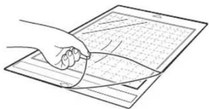
- Do not discard the protective sheet peeled off the mat; save it for later use.
- In order to maintain the adhesive strength, attach the protective sheet to the adhesive side of the mat after use.
- When the mat is not being used, clean the adhesive side and affix the protective sheet before storing it. For details, see “Cleaning the Mat” on page 104.
- Place the material within the attaching area (grid area) on the adhesive side. If the material extends from the attaching area, it may be caught on the feed rollers when the mat is fed, damaging the machine.
- Insert the mat into the machine in the direction of the arrow. Pay attention to the mat's orientation to avoid inserting the mat in the wrong direction.
Material
"Paper" on page 19
"Fabric (Other Than for Quilt Piecing)" on page 20
"Fabric (for Quilt Piecing)" on page 24
Paper

①Mat suitable for the material
□ Attaching the Material (Paper)
1 Peel off the protective sheet from the adhesive side of the mat.


Test attaching the material.
Before attaching the material to the mat, use a corner of the adhesive side of the mat to test attaching it. If any of the following problems occur when test attaching, the adhesive strength of the mat is too high for the material. Use different material.
- When the material is peeled off, color from the material remains on the mat.
- When the material is peeled off, it tears or is deformed.


Note
- Use the low tack adhesive mat with copy paper and smooth paper. Since the standard tack adhesive mat has a high adhesive strength, materials may remain stuck to the mat, causing the mat to become unusable

Attach the material to the mat's adhesive side.
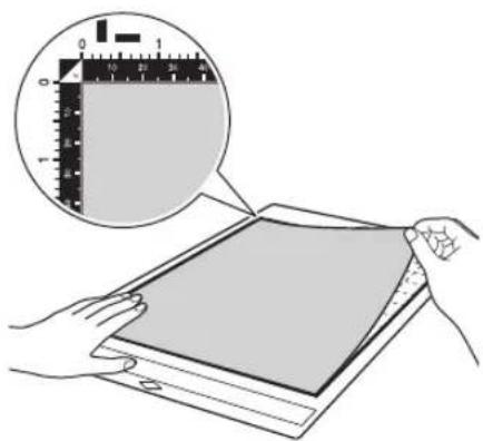

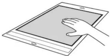
Firmly attach all of the material to the mat so that there are no wrinkles and no part can curl off.
- Otherwise, curls in the material may become caught when the mat is inserted.

Note
- If the mat is dirty, clean it. For details, see "Cleaning the Mat" on page 104.
☐ Peeling Off the Material (Paper)
After cutting the material, use a spatula to slowly peel off the paper.

①Spatula

Note
- When peeling off the material, insert the spatula as level as possible into the space between the material and mat. Strongly rubbing the adhesive side of the mat may damage it.
■Fabric (Other Than for Quilt Piecing)
□ Attaching Fabric Material to a Mat Using Iron-on Fabric Appliqué Contact Sheet
Iron the specially designed contact sheet to the back of fabrics (excluding quilt piecing) and then attach them to the standard tack adhesive mat. The double-faced adhesive type of the iron-on fabric appliqué contact sheet reinforces the fabric and enables any pattern to be cut easily, including appliqués. The sheet cannot be removed once it has been attached to the back of fabrics.
For quilt piecing, use the high tack adhesive fabric support sheet or Fabric mat and avoid using the iron-on fabric appliqué contact sheet. For details on using fabric for quilt piecing, see "Fabric (for Quilt Piecing)" on page 24.
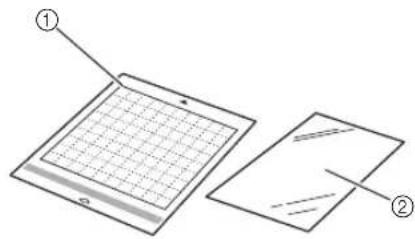
①Standard tack adhesive mat
②Iron-on fabric appliqué contact sheet (white backing)

Note
- The contact sheet may not adhere to a fabric surface that is so rough that the two surfaces cannot be heat-set to adhere to each other.
1 Peel off the protective sheet from the adhesive side of the standard tack adhesive mat.
2 Cut the iron-on fabric appliqué contact sheet to a size 2 cm (3/4") or more larger than the outline of the pattern to be cut.

①Pattern to be cut
②Cutting line of sheet
③Margin of 2 cm (3/4") or more
3 With the glossy side of the contact sheet facing down, place it on the wrong side of the fabric.
Be sure to first iron the fabric to remove any wrinkles. Before placing the contact sheet on the fabric, make sure that the fabric has been allowed to cool after ironing.

①Glossy side of contact sheet
②Wrong side of fabric
4 Evenly iron the entire contact sheet to affix it to the wrong side of the fabric.
With the iron on a medium temperature setting (140 °C to 160 °C (284 °F to 320 °F)), press each part of the sheet for about 20 seconds (the length of time differs depending on the material).
Be sure to apply pressure on the top of the backing and push out any air between the sheet and fabric.

①Backing

Note
- Before attaching the contact sheet to the fabric, use a piece of the sheet to test attach it. If any problems occur when test attaching, use different material.
• Leaving the iron in the same place for too long may scorch or melt the material.
5 Peel off the backing from the contact sheet.
Before peeling off the backing, allow all parts to cool.

①Contact sheet
②Backing
6 With the side of the fabric that the contact sheet is attached to facing down, attach the material to the mat from its edges.
Slowly attach the entire surface of the material from its edges while pressing out any air with a ruler, etc., so that no air is trapped between the mat and the material.


Memo
- Be sure that the vertical grain of the attached fabric runs straight up and down. The built-in patterns are automatically arranged suitable for fabric with vertical grain.
7 Firmly attach all of the material to the mat so that there are no wrinkles and no part can curl off.
- Otherwise, curls in the material may become caught when the mat is inserted.
☐ Peeling Off the Material
After cutting the material, use a spatula to peel off the fabric together with the attached contact sheet.

①Pattern that was cut out
②Contact sheet
③Spatula

Note
- Do not place anything heated on the fabric attached with a contact sheet. Adhesive will permeate any other pieces of fabric around.
- When peeling off the material, insert the spatula as level as possible into the space between the material and mat. Strongly rubbing the adhesive side of the mat may damage it.
□ Attaching Fabrics With the Double-Sided Adhesive
Place a cutout on a base fabric and apply pressure on the top of the cutout using an iron. (The contact sheet may not adhere well to some fabrics.) Hand or machine stitch to ensure that the cutout stays in place.

①Base fabric
②Cutout with a contact sheet

Note
- Do not wash fabrics attached together with a double-sided adhesive contact sheet.
- When attaching fabrics with the double-sided adhesive, iron carefully, being sure that the material and adhesive surfaces are properly heat-set.
- When attaching fabrics of different weights with the double-sided adhesive, first iron the lighter-weight fabric to affix the contact sheet.
- When attaching fabric with an iron-on sheet attached or paper to the mat, cleanly peel off the support sheet from the mat, or attach the material to a different standard tack adhesive mat without a support sheet attached.
□ Notice on Use of Iron-on Fabric Appliqué Contact Sheet
- Store the contact sheet at room temperature and in a location not exposed to high temperatures, high humidity or direct sunlight.
☐ Cutting Fabric Other Than Quilt Pieces Using the Rotary Auto Blade Holder
When cutting fabric (other than for quilt pieces) with the rotary auto blade holder, attach the material directly to the mat appropriate for the material and cut it.

①Mat appropriate for the material
②Rotary auto blade holder
1 Peel off the protective sheet from the adhesive side of the mat.

2 Test attaching the material.
Before attaching the material to the mat, use a corner of the adhesive side of the mat to test attach it. If any problems occur when test attaching, the adhesive strength of the mat is too high for the material. Use different material.

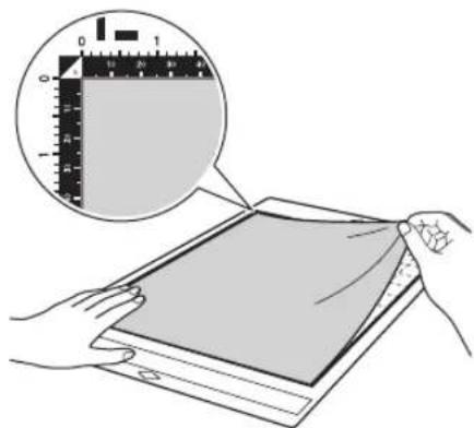
3 From its edges, attach the material to the adhesive side of the mat so that there are no wrinkles in the material.
Be sure to first iron the fabric to remove any wrinkles.

Memo
- Be sure that the vertical grain of the attached fabric runs straight up and down. The built-in patterns are automatically arranged suitable for fabric with vertical grain.
- When drawing a seam allowance, attach the fabric to the mat with its wrong side facing up.
4 Firmly move the spatula handle across the surface of the fabric to remove any wrinkles and firmly attach the fabric to the mat.
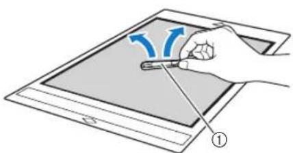
①Spatula
☐ Peeling Off the Material
After cutting the material, use a spatula to slowly peel off the fabric.


①Spatula

Note
- When peeling off the material, insert the spatula as level as possible into the space between the material and mat. Strongly rubbing the adhesive side of the mat may damage it.
■Fabric (for Quilt Piecing)
□ Attaching the Material Using a High Tack Adhesive Fabric Support Sheet
When attaching fabrics for quilt piecing, attach the high tack adhesive fabric support sheet to the standard tack adhesive mat to use it. These sheets should only be used with patterns that have a seam allowance. The high tack adhesive fabric support sheet can be repeatedly used until their adhesive strength has decreased. (Once the support sheet has been peeled off the mat, it can no longer be used.)
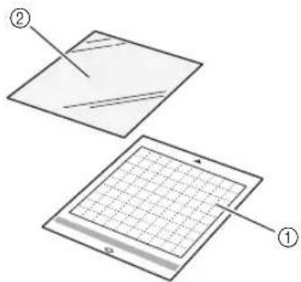
①Standard tack adhesive mat
②High tack adhesive fabric support sheet
1 Peel off the protective sheet from the adhesive side of the standard tack adhesive mat.

2 With the glossy side of the high tack adhesive fabric support sheet facing down, attach it to the mat's adhesive side.
Slowly attach the entire surface of the support sheet from its edges while pressing out any air with a ruler, etc., so that no air is trapped between the mat and the sheet.

①Glossy side of support sheet

Note
- Place the support sheet within the attaching area (grid area) on the adhesive side of the mat. If the sheet extends from the attaching area, it may be damaged by the feed rollers when the mat is fed.
3 Peel off the backing from the top of the support sheet.
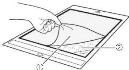
①Backing
②Adhesive
4 Test attaching the material.
Before attaching the material to the mat, use a corner of the adhesive side of the mat to test attach it. If any problems occur when test attaching, the adhesive strength of the mat is too high for the material. Use different material.
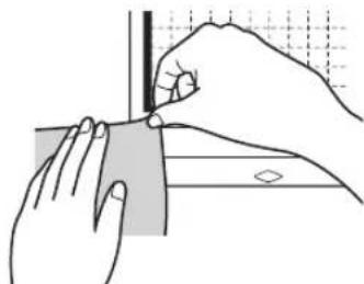
5 From its edges, attach the material to the adhesive side of the mat so that there are no wrinkles in the material.
Be sure to first iron the fabric to remove any wrinkles.


Memo
- Be sure that the vertical grain of the attached fabric runs straight up and down. The built-in patterns are automatically arranged suitable for fabric with vertical grain.
- When drawing a seam allowance, attach the fabric to the mat with its wrong side facing up.
6 Firmly move the spatula handle across the surface of the fabric to remove any wrinkles and firmly attach the fabric to the mat.

①Spatula
☐ Peeling Off the Material (Fabric for Quilt Piecing)
After cutting the material, use a spatula to slowly peel off just the fabric. Try not to peel off the support sheet.
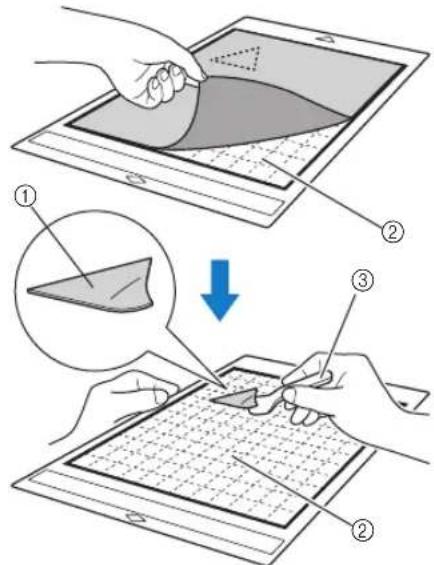
①Fabric cut out
②Support sheet remaining on mat
③Spatula

Note
- The support sheet may be unintentionally peeled off while you are removing the fabric from the mat under the following conditions:
- The adhesive between the mat and support sheet is becoming weak after repeated uses.
- The support sheet tends to be strongly attached to a certain types of fabrics.
- In this case, use the included spatula to hold the support sheet on the mat and remove the fabric using your hand.
• After cutting, carefully remove any fibers remaining on the support sheet. - Do not leave material attached to a mat with a support sheet attached for a long period of time; otherwise, the adhesive will permeate the material.
- When peeling off the material, insert the spatula as level as possible into the space between the material and mat. Strongly rubbing the adhesive side of the mat may damage it.
☐ Notice on Use of High Tack Adhesive Fabric Support Sheet
- When the sheet's adhesive strength decreases or fabric becomes twisted while being cut, replace the sheet with a new one.
- When peeling the sheet off the mat or replacing the sheet, use the spatula to carefully remove the old sheet.
- Store the mat in between uses with the protective sheet affixed to the support sheet.
- If a mat with a support sheet attached is not to be used for a certain length of time, peel the support sheet off the mat and affix the protective sheet on the adhesive side of the mat before storing it.
- Do not reuse a support sheet that has been attached to the mat.
- Store the support sheet at room temperature and in a location not exposed to high temperatures, high humidity or direct sunlight.
- Do not bend the support sheet to store it.
- We recommend attaching it to a new cutting mat.
□ Attaching the Material to the Fabric Mat
When cutting fabric for quilt piecing without using a sheet for fabric cutting, attach the fabric to the fabric mat and cut it.

①Fabric mat
1 Peel off the protective sheet from the adhesive side of the mat.
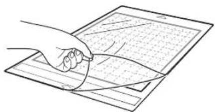
2 Test attaching the material.
Before attaching the material to the mat, use a corner of the adhesive side of the mat to test attach it. If any problems occur when test attaching, the adhesive strength of the mat is too high for the material. Use different material.
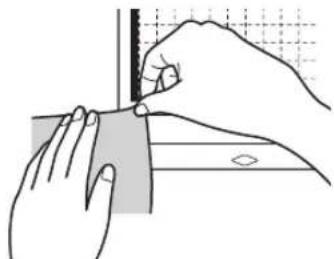
3 From its edges, attach the material to the adhesive side of the mat so that there are no wrinkles in the material.
Be sure to first iron the fabric to remove any wrinkles.
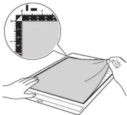

Memo
- Be sure that the vertical grain of the attached fabric runs straight up and down. The built-in patterns are automatically arranged suitable for fabric with vertical grain.
- When drawing a seam allowance, attach the fabric to the mat with its wrong side facing up.
4 Firmly move the spatula handle across the surface of the fabric to remove any wrinkles and firmly attach the fabric to the mat.

①Spatula
☐ Peeling Off the Material (Fabric for Quilt Piecing)
After cutting the material, use a spatula to slowly peel off the fabric.


①Spatula

Note
- When peeling off the material, insert the spatula as level as possible into the space between the material and mat. Strongly rubbing the adhesive side of the mat may damage it.
☐ Cutting Fabric for Quilt Piecing with the Rotary Auto Blade Holder
When cutting fabric (for quilt pieces) with the rotary auto blade holder, attach the material directly to the mat appropriate for the material and cut it. For details, refer to page 22.
Installing and Uninstalling the Holder
Select the holder appropriate for the material, and then install it into the machine. For details on the holder appropriate for the material, see "Reference Table of Mat, Blade and Material Combinations" on page 16.
1 Press in the operation panel to turn on the machine.
For details, see "Turning On/Off the Machine" on page 8.

Note
- Be sure to turn on the machine before installing the holder.
- If the holder is installed while the machine is off, the blade may break and material may not be cut cleanly.
2 Remove the protective cap.


Note
- Please remove protective cap from blade holder before placing it into the machine carriage.

WARNING
- This is not a toy and is not intended to be used by children. In order to prevent choking hazards, do not allow infants/children to put the protective caps in their mouths.

CAUTION
- Do not press the tip of the holder with your hand or fingers because the tip of the blade will extend and may result in injuries.
- Do not touch the tip of the blade with your hands or fingers. There is a risk of injury.
3 Grasp the holder grip, and then insert the holder into the carriage.

①Grip
4 Push down on the holder lock lever.
Firmly push down until the holder is locked in place.

①Holder lock lever
5 Reverse the installation procedure to uninstall the holder.

WARNING
- This is not a toy and is not intended to be used by children. In order to prevent choking hazards, do not allow infants/children to put the protective caps in their mouths.

CAUTION
• After removing the blade holder from the machine, be sure to attach the protective cap.
- Do not press the tip of the holder with your hand or fingers because the tip of the blade will extend and may result in injuries.
- Do not touch the tip of the blade with your hands or fingers. There is a risk of injury.
Test Cut (Trial Cut)
Perform test/trial cut or draw on the type of material to be used in your project, to check that the desired result can be achieved.
This section describes the procedure for performing test cut.
■Turning On the Machine
Press ☑ the operation panel to turn on the machine.
- For details, see "Turning On/Off the Machine" on page 8.
■Setting the Holder
Install the cutting blade holder into the carriage of the machine.
- For details, see "Installing and Uninstalling the Holder" on page 27.
■Selecting the Test Pattern
Cut out the test pattern.
1 Touch the "Test" key in the home screen.

The pattern is automatically arranged in the test screen.

Memo
- Test/trial cut can also be performed after selecting an operation in the preview screen, displayed after a pattern is selected. For details, see “Tutorial 1 - Cutting Patterns” on page 32.

2 Check that the pattern to be cut out is arranged within a cutting area specified according to the size of the material.

①Pattern Arrangement Key
Touch to make adjustments in the mat editing screen when changing the arrangement of the pattern. If changes are applied to the pattern arrangement, the pattern will be automatically arranged in the same location the next time test/trial cut is performed.
②Size/Shape Adjustment Key
Touch to adjust the pattern shape and size. For details on making changes, see step 3.
③Background Scanning Key
Scan a background image. For details, see "Scanning a Background Image" on page 54.
3 To change the shape and size of the pattern,
touch

①Size Adjustment Keys
Change the size of the pattern. For details, see "Pattern Editing Functions" on page 44.
②Test Pattern Selecting Keys
Select the test pattern.
③Test Pattern Rotating Key
Rotate the test pattern. Touch the key that shown in the screen for the desired angle to rotate the pattern. For details, see "Object Editing Screen" on page 47.
④Test Pattern Fill/Additional Line Setting Keys Select whether or not to fill or add lines to the test pattern. These functions are not available when you select the "Cut" or "Emboss" operation mode.
▶ Touch the "OK" key to return to the test screen.
■Loading the Mat
1 Attach the material that will be cut to the mat.
- For details on attaching material to the mat, see "Attaching the Material to the Mat" on page 19.
2 While holding the mat level, gently insert it into
the feeding slot and press the ☐ on the operation panel while gently pushing the mat forward.
Insert the tip of the mat so that it aligns with the guides on the left and right sides of the feed slot and is tucked under the feed rollers. Insert the end of the mat marked with an arrow into the machine.

①Guides
②Feed rollers

The mat is fed in to complete the preparations for cutting.

Note
- Do not forcefully pull the mat while it is being fed in. Otherwise, damage, for example, to the feed rollers, may result.
Cutting
1 Select "Cut" in the test screen.
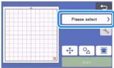


Note
- To make half cuts (kiss cuts), turn on half cut (kiss cut) in the settings screen. For details on specifying the settings, see "Half Cut (Kiss Cut) Settings" on page 31.
2 Touch the "Start" key to start cutting.
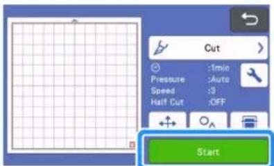
When cutting is finished, the message "Finished cutting." appears on the display. Touch the "OK" key to return to the test screen.
■Unloading the Mat
1 Press in the operation panel to feed out the mat.
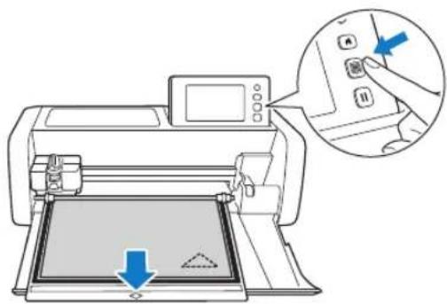

Note
- Do not forcefully pull the mat while it is being fed out. Otherwise, damage, for example, to the feed rollers, may result.
2 Peel off the material from an area that is easily removable, such as a corner, and then slowly peel while maintaining an even pressure.

3 Holding the mat with your hand, use the included spatula to carefully peel off the cut-out patterns.

①Spatula

Note
- When peeling off the material, insert the spatula as level as possible into the space between the material and mat. Strongly rubbing the adhesive side of the mat may damage it.
■Checking the Test/Trial Cut Results
Adjust the cutting pressure according to the test/trial cut results.
Repeatedly perform test/trial cut and adjust the cutting pressure until the material is cut cleanly.
☐ With an Appropriate Cutting Pressure
When the material is peeled off, a faint trace of the cut remains on the mat surface.
![graph TD A["Gray rectangle with triangle symbol"] --> B["Blue arrow pointing to a grid graph with triangle symbol"]](/content/2026/05/937368/images/1be901a8d7cc81c7dc8ef8cb2c28445bb25ca816d3b73471afff0934fe5a8732.jpg)
■Changing the Auto Cutting Pressure
If the material could not be cut cleanly, refer to the following table, and adjust the setting for the cutting pressure.
| Test/Trial Cut results | Tips for adjustment |
| Part of the pattern is not cut. | Pressure too light: Touch in the settings screen once to increase the pressure. |
| The entire pattern is not cut. | Pressure too light: Touch in the settings screen once to increase the pressure. |
| There are deep cuts completely through the mat. | Pressure too strong: Touch in the settings screen once to decrease the pressure. |
□ Changing the Cut Pressure Setting
1 Touch in the test screen to display the settings screen.

2 Touch or to adjust the cutting pressure, and then touch the "OK" key.
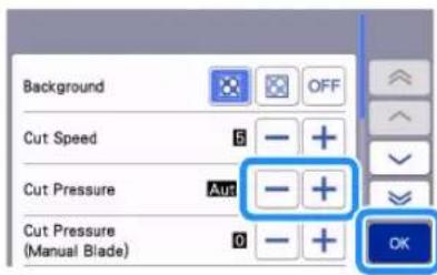
3 Check that the settings have changed in the test screen, and then perform test/trial cut again.


Note
- Be careful not to increase the pressure too much. Otherwise, the blade may break. If the pressure is too strong, the material may not be cut cleanly. In addition, the mat will deteriorate more quickly.
■Half Cut (Kiss Cut) Settings
To make half cuts (kiss cuts), turn on half cut (kiss cut) in the settings screen before beginning to cut.
1 Touch in the preview screen to display the settings screen.
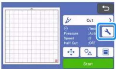
2 Turn on "Half Cut", and then touch the "OK" key.
- The pressure for half cut (kiss cut) can adjusted with "Cut Pressure (Half Cut)". Adjust the cutting pressure until half cut (kiss cut) result is as desired.

PATTERN CUTTING
The following procedures use built-in patterns to describe the entire series of operations, from selecting a pattern and editing it to cutting.
Tutorial 1 - Cutting Patterns
![graph TD A["Star Symbol"] --> B["Clover Icon"] B --> C["Card Icon"] D["Star Symbol"] --> E["Star Icon"] style A fill:#f9f,stroke:#333 style B fill:#ccf,stroke:#333 style C fill:#cfc,stroke:#333 style D fill:#fcc,stroke:#333](/content/2026/05/937368/images/4a1f78eb4c5cb4eae845e0e7905f94f94ccd2d321fd6ad27c663f39e04d86bdf.jpg)
In this tutorial, we will cut two built-in patterns.
■Turning On the Machine
Press to turn on the machine.
- For details, see "Turning On/Off the Machine" on page 8.
■Setting the Holder
Install the cutting blade holder into the carriage of the machine.
- For details, see "Installing and Uninstalling the Holder" on page 27.
■Selecting and Editing the First Pattern
1 Select "Pattern" in the home screen.
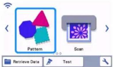
2 Select the category for the pattern to be cut out in the pattern category selection screen.
For this example, select


①Touch to return to the previous screen.
②Pattern categories

Memo
- The pattern categories and built-in patterns that appear in the operation screens differ depending on the machine model. For details on the built-in patterns, refer to the "Pattern List". The "Pattern List" can be downloaded from the Brother support website (http://s.brother/cmoae/).
3 Select the first pattern to be used in the pattern selection screen.
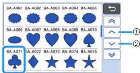
①Touch to scroll up.
②Touch to scroll down.
4 Edit the size and number of the pattern using the pattern editing screen.
After editing is finished, touch the "Set" key.
- For details on the editing functions, see "Pattern Editing Functions" on page 44.
- To select a different pattern, touch , cancel the selection, and then select a pattern again.

■Selecting and Editing the Second Pattern
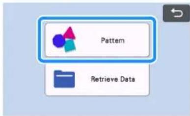
1 Touch the "Add" key in the mat layout screen.

2 Select the location of the pattern to be added.
- For this example, touch the "Pattern" key to add a built-in pattern. For details on recalling pattern data, see step 3 in "Retrieve Data" on page 66.
3 Select the category for the pattern to be cut out.

①Touch to return to the previous screen.
4 Select the second pattern to be used.
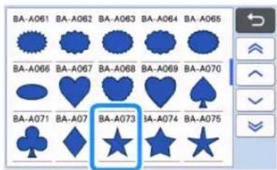
5 Edit the pattern.
After editing is finished, touch the "Set" key.
- For details on the editing functions, see "Pattern Editing Functions" on page 44.
- To select a different pattern, touch , cancel the selection, and then select a pattern again.

6 Check the pattern arrangement.
The two patterns that will be cut out appear in the mat layout screen. After checking the arrangement, touch the "OK" key.
- From this screen, an individual pattern can be edited, moved or deleted. For details on the functions that can be used in the mat layout screen, see "Layout Editing Functions" on page 46.
- By using the auto layout function, the arrangement of the patterns can easily be adjusted. For details, see "Auto Layout Functions" on page 54.
- Select the "Cut Area" setting appropriate for the mat being used. (See page 10.)
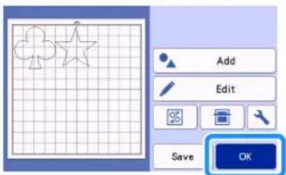
The preview screen appears.

Note
- Depending on the pattern type and material to be cut, the patterns may not be cleanly cut if their spacing is too small. In that case, rearrange the patterns to separate them.

Memo
- To move a pattern within the cutting/drawing area, touch the pattern on the screen and drag it to the desired position.

- To delete a pattern from the arrangement, select the pattern in the mat editing screen, and then use the function for deleting.
▶ Touch the "Edit" key in the mat layout screen.
▶ Touch the pattern to be deleted in the screen. To delete multiple patterns, use the function for selecting multiple patterns. For details, see "Selecting Multiple Patterns" on page 42.
▶ Touch the mat editing screen to delete the selected pattern(s).

■Loading the Mat
While holding the mat level and lightly inserting it into the feed slot, press in the operation panel.
- For details, see "Loading the Mat" on page 29.
Cutting
1 Select "Cut" in the preview screen.
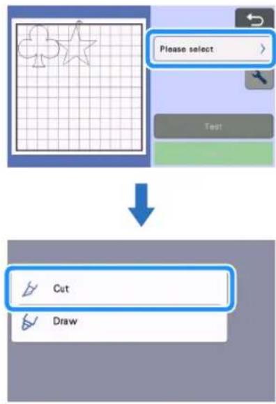

Note
- Before continuing operation, make sure that patterns that will be cut out are arranged in the cutting area corresponding to the size of the material to be used.
- To make half cuts (kiss cuts), turn on half cut (kiss cut) in the settings screen before beginning to cut. For details, see "Half Cut (Kiss Cut) Settings" on page 31.

Touch the "Start" key to start cutting.

When cutting is finished, the preview screen appears again.

Note
- Touch the "Test" key in the preview screen to perform test/trial cut. When test/trial cut is finished, the following screen appears.

- Touch the "Start" key to start cutting the pattern.
- Touch the "Test again" key to return to the test screen. Change the settings, and then perform test/trial cut again.
■Unloading the Mat
Feed out the mat, and then use the included spatula to peel off the patterns.
For details, see "Unloading the Mat" on page 30.

Tutorial 2 - Cutting Advanced Patterns
![graph TD A["Crown Icon"] --> B["Clay Icon"] B --> C["Clay Icon with Arrow"] C --> D["Clay Icon with Arrow"]](/content/2026/05/937368/images/cf1f314e72bbf982bac9e7121393505ed819ceb656f5eb3a2a0f90285c0fb611.jpg)
In this tutorial, we will use a built-in pattern in the

category to cut different materials for each
part.
■Selecting and Editing the First Pattern Piece
1 Select "Pattern" in the home screen.

2 Select the category in the pattern category selection screen.
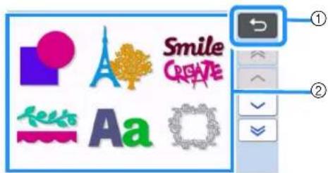
①Touch to return to the previous screen.
②Pattern categories

Memo
- The pattern categories and built-in patterns that appear in the operation screens differ depending on the machine model. For details on the built-in patterns, refer to the "Pattern List". The "Pattern List" can be downloaded from the Brother support website (http://s.brother/cmoae/).
3 Select the sub-category in the pattern sub-category selection screen.

4 Select the pattern to be cut out in the pattern selection screen.
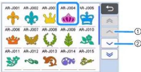
①Touch to scroll up.
②Touch to scroll down.
5 Edit the size of the entire pattern using the pattern sizing screen.
After editing is finished, touch the "OK" key.
- For details on the pattern sizing screen, see "Pattern Sizing" on page 45.

6 Select the piece to be edited first in the pattern piece list screen, and then touch the "OK" key.
From the pattern piece list that appears in the screen, touch a pattern piece to edit it individually.


Memo
- The pattern pieces displayed in the pattern piece list screen are automatically arranged so that the grain is vertical when fabric is used as the material for cutting. Therefore, the angle at which the pattern appears in the pattern piece list may differ from the actual angle of the pattern piece to be cut out.
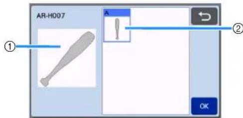
①Appearance in pattern piece list
②Actual arrangement of the pattern piece to be cut out
- Change the angle of pattern piece using the rotating function according to your project. For details, see "Editing the Pattern Piece" on page 45.
- A key showing all pattern pieces appears at the end of the pattern piece list. Press this key to select all pattern pieces and arrange them on the mat. This key is useful when cutting the pattern outline and cutting multiple pattern pieces within the same mat, see “Editing and Cutting the Second Pattern Piece” on page 38.

7 Edit the pattern piece using the pattern piece editing screen.
After editing is finished, touch the "Set" key.
- For details on the editing functions, see "Editing the Pattern Piece" on page 45.
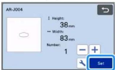
8 Check the pattern piece arrangement using the mat layout screen.
The pattern piece to be cut out appears in the screen. After checking the arrangement, touch the "OK" key.
- From this screen, an individual pattern piece can be edited, moved, deleted or saved. For details on the editing functions in the mat layout screen, see "Mat Layout Screen" on page 45.
- Select the "Cut Area" setting appropriate for the mat being used. (See page 10.)
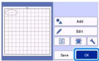
The preview screen appears.
■Loading the Mat
Attach the material that the first pattern piece will be cut out of to the mat, and then feed in the mat from the feed slot.
When cutting a pattern consisting of multiple pieces in different colors, edit the pattern piece for each color, and then change the material to cut out each piece.
- For details on preparing the material and loading the mat, see "Loading the Mat" on page 29.
■Cutting the First Pattern
1 Select "Cut" in the preview screen.


Note
- Before continuing operation, make sure that patterns that will be cut out are arranged in the cutting area corresponding to the size of the material to be used.
- To make half cuts (kiss cuts), turn on half cut (kiss cut) in the settings screen before beginning to cut. For details, see "Half Cut (Kiss Cut) Settings" on page 31.
2 Touch the "Start" key to start cutting.
After the first pattern piece has been cut out, the following message appears. In order to cut out the second pattern piece, touch the "Select the next part" key.
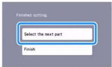
Touching the "Select the next part" key erases all editing information for the first pattern piece and displays the pattern piece list screen again.
■Unloading the Mat
1 Press in the operation panel to feed out the mat.
In order to replace the material with one of a different color, the material used for the first pattern piece must be fed out.
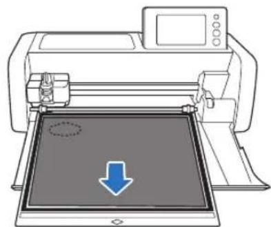
2 Peel from the mat the pattern piece that was cut out.
For details on peeling the material from the mat, see "Unloading the Mat" on page 30.
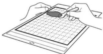
■Editing and Cutting the Second Pattern Piece
1 Select and edit the second pattern piece, and then touch the "OK" key.
For details on editing the pattern, follow steps 6 - 8 (page 36) in "Selecting and Editing the First Pattern Piece".
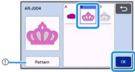
①Touch to return to the pattern category selection screen for selecting another pattern.
2 Follow the procedures described in "Loading the Mat" (page 29) and "Cutting" (page 29) to load the material to be used for the second pattern piece and cut it out.
When cutting is finished, a message appears.
3 After all pattern pieces have been cut out, touch the "Finish" key.
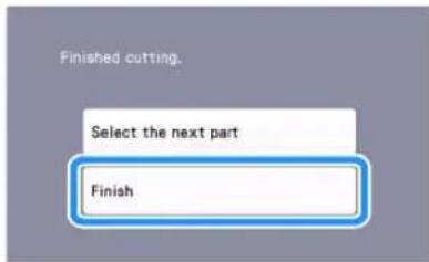
The preview screen appears again.
■Unloading the Mat
Peel from the mat the pattern piece that was cut out. For details on peeling the material from the mat, see "Unloading the Mat" on page 30.

■Editing and Cutting the all Pattern Pieces
☐ Cutting the pattern outline
1 Select and edit the all pattern pieces, and then touch the "OK" key.

2 Edit the pattern piece using the pattern piece editing screen.
- For details on the editing functions, see "Editing the Pattern Piece" on page 45.

3 Touch to ungroup the pattern pieces.
After editing is finished, touch the "Set" key.

①Grouping/Ungrouping Key
Memo
- Grouping/Ungrouping patterns can also be adjusted in the object editing screen. For details, see "Grouping/Ungrouping Patterns" on page 48.
4 Check the pattern piece arrangement using the mat layout screen and then touch the "Edit" key.
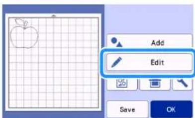
5 Touch the "Object Edit" key.

6 Touch to weld the pattern.
- For details on the welding, see "Welding (Merging the Outlines of Multiple Patterns)" on page 50.

▶ Touch the "OK" key in the editing screen to return to the mat layout screen.
7 Touch the "OK" key.

8 Follow the procedures described in "Loading the Mat" (page 29) and "Cutting" (page 29) to load the material to be cut.
When cutting is finished, a message appears.
9 After all pattern pieces have been cut out, touch the "Finish" key.

☐ Cutting all the pattern piece within the same mat
1 Select and edit the all pattern pieces, and then touch the "OK" key.

2 Edit the pattern piece using the pattern piece editing screen.
- For details on the editing functions, see "Editing the Pattern Piece" on page 45.

3 Touch to ungroup the pattern pieces.
After editing is finished, touch the "Set" key.

①Grouping/Ungrouping Key
4 Check the pattern piece arrangement using the mat layout screen and then touch arrange all the pattern pieces layout automatically.
- For details on the auto layout function, see "Auto Layout Functions" on page 54.
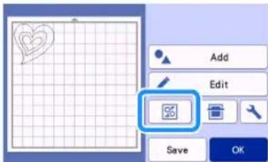
▶ Touch the "OK" key in the editing screen to return to the mat layout screen.
5 Touch the "OK" key.
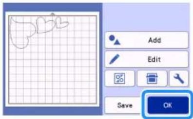
6 Follow the procedures described in "Loading the Mat" (page 29) and "Cutting" (page 29) to load the material to be cut.
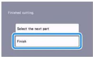
When cutting is finished, a message appears.
7 After all pattern pieces have been cut out, touch the "Finish" key.
Tutorial 3 - Adding a Weeding Box to a Pattern
In this tutorial, we will be adding a weeding box to cut a pattern to make it easier to do "weeding" work to remove only the unnecessary parts after cutting materials with backing paper or backing film.
1 After editing the pattern, select "Cut" in the preview screen.
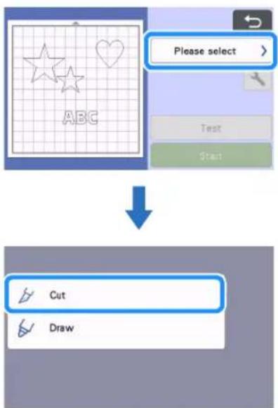
2 Touch, and then set "Weeding Box" to "ON" to add weeding boxes.
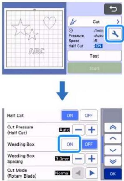
▶ A weeding box is added around each pattern.
Memo
- If patterns are close to each other, the weeding box is added as if the patterns are one group, even if they are not grouped.
- A weeding box is not added to test patterns.
- If the weeding box is outside of the cutting area, the following message appears and the weeding box is not added.

Touch the "Cancel" key, and then either reduce the setting for "Weeding Box Spacing" or return to the editing screen and adjust the arrangement of the patterns.
3 Touch the "Start" key to start cutting.

After cutting is finished, "Weeding Box" is set back to "OFF".
To change the distance of the weeding box from the pattern, change the setting for "Weeding Box Spacing" in the settings screen.


PATTERN SELECTION
The following four pattern selection functions are available in the mat editing screen depending on your preference:
- Selecting a Single Pattern
- Selecting Desired Patterns
- Selecting All Patterns
●Specifying the Selection Area
▶ Touch the "Edit" key in the mat layout screen to use the pattern selection functions.

Selecting a Single Pattern
Select an individual pattern to be edited by either touching it in the editing screen or using and

The selected pattern is surrounded with a red box.
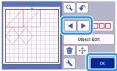
Selecting Multiple Patterns
■Selecting Desired Patterns

Touch in the mat editing screen for making multiple pattern selection.
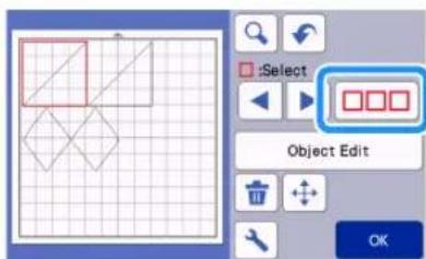
2 Individually touch all the patterns you want to select in the screen, and then touch the "OK" key.
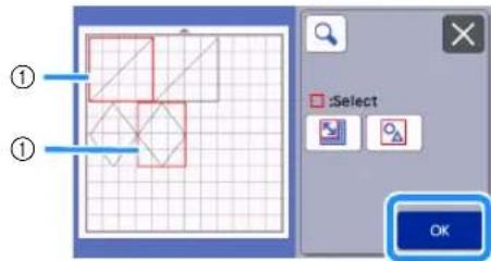
①Selected patterns

Memo
- Touching a selected (surrounded with a red box) pattern again clears its multiple selection.
- Touching any blank space in the screen clears all the pattern selections.
■Selecting All Patterns
1 Touch in the mat editing screen for making multiple pattern selection.
2 Touch to select all the patterns on the screen.

3 Check the selection, and then touch the "OK" key.
All the selected patterns are surrounded with a red box.

■Specifying the Selection Area
1 Touch in the mat editing screen for making multiple pattern selection.
2 Touch for specifying an area to select the patterns.


Memo
- Make sure that is not selected before specifying the area to select.
3 Touch and drag the area resizing keys to specify the area, and then touch the "OK" key.
![graph TD A["Device ①"] --> B{Status Indicator} B --> C["Device ②"] C --> D["Device ③"] D --> E["OK"]](/content/2026/05/937368/images/2310b6d86a155369ad0a9a7d7c56761c2b5615b30f260cbb83ac22e934883629.jpg)
①Keys for specifying the area
②Patterns to be selected

Note
- Make sure to specify to include more than two patterns in the area.
- This method of selecting patterns within a specified area is useful for welding or unifying patterns and deleting unwanted images when scanning (page 50, page 79).
Chapter 3 ADVANCED OPERATIONS
CUTTING AND EDITING FUNCTIONS
Pattern Editing Functions
The pattern editing functions available may differ depending on the pattern you select. Follow the instructions in either this section or "Pattern Editing Functions - Multiple Patterns" on page 45.
Available in the following screen
Pattern editing screen
→Tutorial 1; Step 4 (page 32) in "Selecting and Editing the First Pattern"
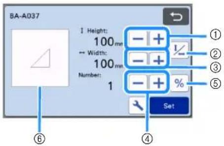

Note
- Depending on the pattern being used, the material may not be cut cleanly, if reducing the size of the pattern. Before making your project, perform test/trial cut with the same material.
①Sizing (Height)
Edit the pattern height while maintaining the aspect
ratio. Touch or to adjust the setting. Touch

to edit only the height.

② Unlocking the Aspect Ratio
Touch to edit the pattern size without
maintaining the aspect ratio. The function is available depending on the pattern you select. If the key is not available, the aspect ratio is locked and the pattern can only be edited while maintaining the aspect ratio.
③Sizing (Width)
Edit the pattern width while maintaining the aspect ratio. Touch or to adjust the setting. Touch

to edit only the width.
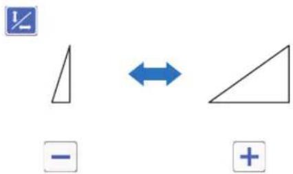
④Duplicating (Pattern Quantity)
Create duplicate(s) of the selected pattern. Touch

or to specify the pattern quantity.

⑤Re-sizing (% specification)
Touching changes the size to a 100% display. Change the size of a pattern while maintaining the aspect ratio.
Touch either or to change the settings.
Touch again to return to millimeter/inch units.
Setting values that were re-sized with a specified percentage are recorded as 100%.
⑥Previewing
Display a preview of the edited pattern.
Pattern Editing Functions - Multiple Patterns
The pattern editing functions available may differ depending on the pattern you select. Follow the instructions in either this section or "Pattern Editing Functions" on page 44.
■Pattern Sizing
Available in the following screen
| Pattern sizing screen | →Tutorial 2; Step ⑤ (page 36) in "Selecting and Editing the First Pattern Piece" |
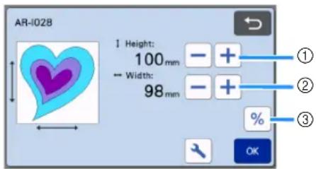
①Touch to edit the pattern height (while maintaining the aspect ratio).
②Touch to edit the pattern width (while maintaining the aspect ratio).
③Change the size of the pattern with the setting (while maintaining the aspect ratio).

Memo
- All the pattern pieces displayed on the pattern sizing screen can be resized while maintaining the aspect ratio.
■Editing the Pattern Piece
Available in the following screen
| Pattern piece editing screen | →Tutorial 2; Step ⑦ (page 36) in "Selecting and Editing the First Pattern Piece" |

①Duplicating (Pattern Quantity)
For details, see "Pattern Editing Functions" on page 44.
Mat Layout Screen
The arrangement of the patterns can be edited. The cutting/drawing area specified with the "Cut Area" setting (page 10) in the settings screen is displayed in the preview screen. Edit the pattern arrangement so that the patterns fit within the specified area.
Available in the following screen
| Mat layout screen | →Tutorial 1; Step 6 (page 33) in "Selecting and Editing the Second Pattern" |
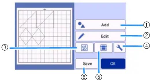
①Adding Patterns
Add a pattern to the layout.
▶ Touching this key displays the selection screen for an additional pattern. From that screen, select the location of the pattern to be added.
②Editing
The patterns in the layout can be edited, moved or deleted. For details, see “Layout Editing Functions” on page 46.
③Auto Layout
Automatically arrange the patterns to reduce their spacing. For details, see "Auto Layout Functions" on page 54.
④Settings
Specify the cutting area, pattern spacing and background contrast. For details, see “Settings Screen” on page 10 or “Scanning a Background Image” on page 54.
⑤Background Scanning
Scan the material for cutting/drawing to be displayed in the background of the mat layout screen. You can use specific areas of the material to cut out/draw patterns, or display the material that has already been cut in order to reuse it. For details, see "Scanning a Background Image" on page 54.
⑥Saving
Save the pattern arrangement as data. For details, see "Saving" on page 65.
Layout Editing Functions
The layout editing functions are available when the "Edit" key is touched in the mat layout screen.
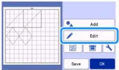
The mat editing screen appears.
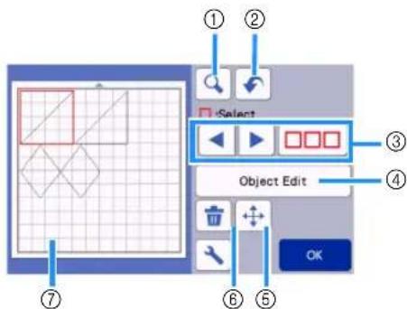
①Magnifying
Zoom in on the pattern at 200%. Then, touch

200%
to display the patterns enlarged by
400%. To scroll through the screen, touch the arrow keys.


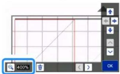
②Undoing an Operation
Undo the last operation to return to the previous condition. For details, see “Undoing an Operation” on page 48.
③Selecting Patterns
Select an individual pattern or multiple patterns to be edited. For details, see "PATTERN SELECTION" on page 42.
④Object Edit
The selected pattern can be edited in more detail. For details, see "Object Editing Screen" on page 47.
⑤Moving
Incrementally move the selected patterns. Touch the arrow keys to adjust the position of the patterns.
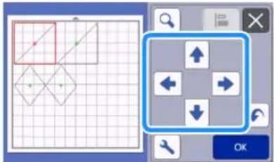

Memo
- The pattern can also be moved by touching it displayed in the layout editing screen and dragging it in the screen.
- To move a pattern while in the zoom mode, drag the pattern or touch the arrow key after selecting the pattern.
- Touch the arrow key once to move the selected pattern 0.5 mm (5 mm when the key is held down).

⑥Deleting
Delete the selected patterns.
⑦Previewing
Display a preview of the edited pattern.
Object Editing Screen

①Sizing
Change the size of the selected pattern.
▶ Touching this key displays the pattern sizing screen. From that screen, the height and width of the pattern can be changed.
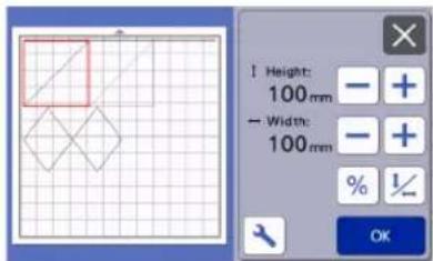
②Duplicating (Pattern Quantity)
Create a duplicate of the pattern.
③Rotating
Rotate the pattern.
▶ Touching this key displays the pattern rotation screen. From that screen, touch the key for the desired angle to rotate the pattern.


④Seam Allowance
Apply the seam allowance setting. Apply this setting when cutting around a drawn pattern, such as when making appliqué or quilt pieces. When applied, the drawing line (blue) and cutting line (black) appear.
- For details on the seam allowance function, see "Cutting Around Drawings" on page 59.


Memo
- Depending on the pattern, the seam allowance may be applied as a default. Check the setting. - If the cutting line of a pattern extends from the cutting/drawing area due to editing, such as by applying a seam allowance or flipping a pattern, the line will become gray. Continue editing the pattern to move it within the cutting/drawing area.
⑤Mirroring
Flip the pattern along a vertical axis.

⑥Fill
Select settings for filling patterns. For details, see "Using Drawing Functions to Fill Patterns/Make Outlines Thicker" on page 63.
⑦Additional Line
Specify the number of lines to be added. For details, see "Using Drawing Functions to Fill Patterns/Make Outlines Thicker" on page 63.
⑧Adding Offset Lines
Offset lines can be added to a selected pattern. Offset lines can be set with cut, draw, and other extensions. For details, refer to "Adding an Offset Line to the Pattern" on page 51.
⑨Converting Cutting Lines to Dotted Lines
Convert a selected pattern with dotted lines. Use this when making holes in a pattern with the paper piercing tool. For details, refer to the instruction manual of the optional paper piercing starter kit.
⑩Grouping/Ungrouping Patterns
When multiple patterns are selected, those patterns can be unified together and edited as a single pattern. This is useful for increasing or reducing the size of multiple patterns at one time. For selecting multiple
patterns, touch in the mat editing screen. For details, see "Grouping/Ungrouping Patterns" on page 48.
⑪ Welding (Merging the Outlines of Multiple Patterns)
Weld the outlines of multiple patterns to create a single outline. For details, see "Welding (Merging the Outlines of Multiple Patterns)" on page 50.
⑫Alignment
Select multiple patterns to align them based on their positions or heights. For details, see "Aligning Patterns" on page 52.
Undoing an Operation
In the editing screen after patterns have been arranged in the mat, touch to undo the previous operation.
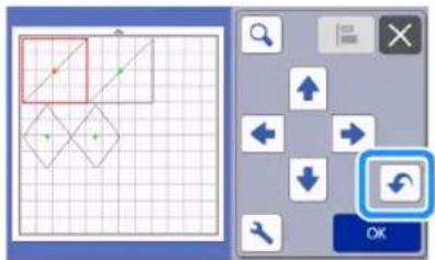

Memo
- Up to 10 of the previous operations can be undone.
• After an operation is undone, it cannot be redone. - If the number of patterns has changed as a result of adding, removing, welding or unifying patterns, only operations after the number of patterns were changed can be undone.
- When patterns are automatically arranged, the operation cannot be undone.
Grouping/Ungrouping Patterns
Multiple patterns selected can be combined into a single group, or that group can be separated into the individual patterns.
(Under some conditions, it may not be possible to ungroup patterns. For the conditions where patterns cannot be ungrouped, refer to page 49.)
■Grouping Patterns
1 Touch in the mat editing screen, select the patterns to be grouped, and then touch the "OK" key.
- For details on selecting multiple patterns, see "Selecting Multiple Patterns" on page 42.

① Selects the patterns in the selection area.
②Selects all patterns in the layout.
2 Touch the "Object Edit" key in the mat editing screen.
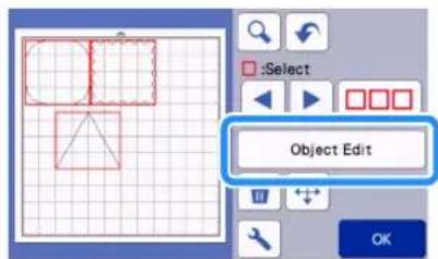
3 Touch in the object editing screen.


All of the selected patterns are grouped. (The color of the key changed.)

Memo
- The key color indicates how the selected patterns are grouped.
- : Two or more patterns are selected and can be grouped. When the key is touched, it appears as .
- : The patterns are grouped. (The color of the key changed.) When the key is touched, it appears as .
- : Since two or more patterns are not selected, patterns cannot be grouped.
- Patterns cannot be grouped under the following conditions.
- There is not enough of the machine's memory available.
- Patterns with and without seam allowances have been selected.
■Ungrouping Patterns
1 Select grouped patterns in the mat editing screen, and then touch the "Object Edit" key.
2 Touch in the object editing screen.


The selected patterns are ungrouped. (The color of the key changed.)

Memo
- I appears when patterns are selected, the patterns can be ungrouped. - Grouped patterns are saved as one pattern. When the saved pattern is recalled, it cannot be ungrouped. When saving a pattern that contains grouped patterns, the following message appears.

- Patterns cannot be ungrouped under the following conditions.
- The number of patterns after being ungrouped exceeds the maximum number of patterns possible. - The pattern was retrieved from the resume memory after an auto shutdown.
Welding (Merging the Outlines of Multiple Patterns)
When multiple patterns are selected, the outlines of those patterns can be welded to create a single outline.
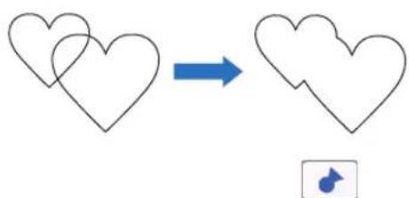
1 Select two heart patterns of different sizes and arrange them in the mat layout screen.
2 Touch the large heart pattern in the mat layout screen, and then drag it over the small pattern.

3 Touch in the mat editing screen.
- For details on the functions in the mat editing screen, see "Layout Editing Functions" on page 46.

4 Select, and then touch the "OK" key.
- Two pattern selection functions are available depending on your preference. For details on selecting multiple patterns, see "Selecting Multiple Patterns" on page 42.

5 Touch the "Object Edit" key in the mat layout screen.
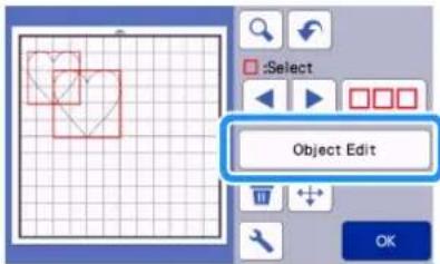
6 Touch in the object editing screen.

7 Check the preview, and then touch the "OK" key.


Note
- Welding pattern outlines cannot be undone. In order to recreate the original pattern arrangement, select the patterns again, and then arrange them.
The outlines of the selected patterns are welded.
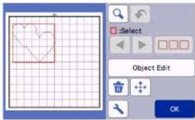

Note
- This function welds the outermost outline of the patterns. When welding certain types of patterns that have inside areas cut out, the cut-out areas are not used to create the outline. Be sure that the welded patterns in the preview area meet your wishes before completing the procedure.
- Welding built-in characters

- Welding character images created by scanning

Adding an Offset Line to the Pattern
An offset line can be added to the selected pattern. Offset line setting can be used for cutting, drawing and other premium functions.

Touch in the object editing screen, and then add an offset line to the pattern.
- The selected original design/pattern appears in green.
- The newly added offset line appears in black.
- After the offset distance has been specified, it cannot be changed. First, delete the added offset line and then display the offset setting screen to add a new offset line.


Touch or to adjust the setting.
- Specify a negative setting for "Offset Distance" to create an offset line inside the pattern, or specify a positive setting to create an offset line outside the pattern.

![graph LR A["Green Star Shape"] -->|+| B["White Star Shape"] A <-->|-| C["Blue Star Shape"] C --> D["White Star Shape"] style A fill:#fff,stroke:#000 style B fill:#fff,stroke:#000 style C fill:#fff,stroke:#000 style D fill:#fff,stroke:#000](/content/2026/05/937368/images/b4371233a70c106b229680c0c1c4a592b2e7e88814f19ac4034a2df734c261dc.jpg)
①Offset line
②Original pattern

Memo
- If a positive setting was specified to create an offset line outside the pattern, the corners of the offset line will be beveled.
Aligning Patterns
Multiple patterns can be selected and aligned based on their positions or heights.
1 Select two or more patterns in the mat editing screen, and then touch the "Object Edit" key.
- For details on selecting multiple patterns, see "Selecting Multiple Patterns" on page 42.
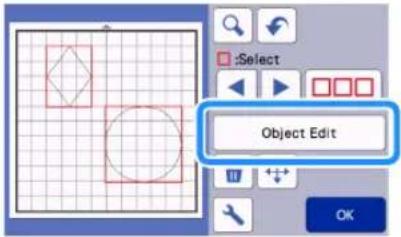

Memo
- The alignment key () can also be displayed in the pattern moving screen.
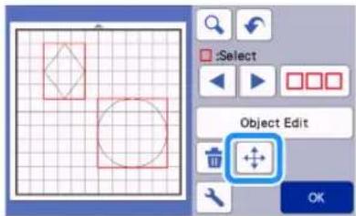
2 Touch in the object editing screen.
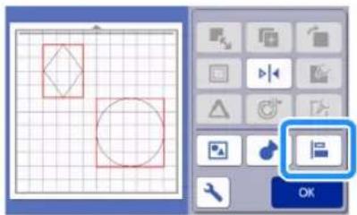
3 Align the patterns.
- The patterns are aligned depending on the key that is touched, as described below.

Original
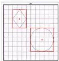
①

②

③


④

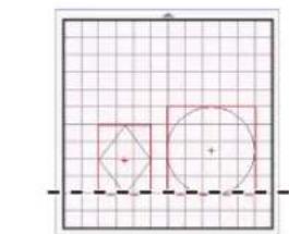
⑤


⑥
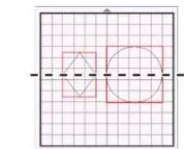
- If three or more patterns were selected, they can be distributed horizontally (⑦) or vertically (⑧).

Original
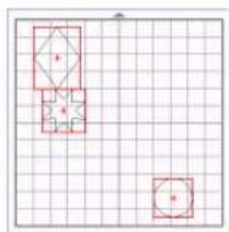
⑦

⑧


Note
- When patterns are distributed, they may extend out the mat. Adjust the pattern positions according to the message instructions.

Touch the "OK" key to return to the object editing screen.
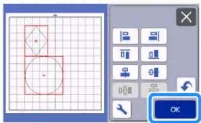
- Touch to return to the object editing screen without applying the pattern arrangement.
■Centering Two or More Patterns
1 Add two circle patterns, and then change the size of one.
- For details on resizing patterns, see "Object Editing Screen" on page 47.
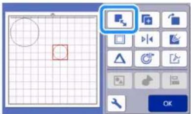

After selecting two patterns, touch in the object editing screen to display the following screen. After touching and to align the patterns, touch the "OK" key.
![graph TD A["Start: Drawing Icon"] --> B["Step 1: Click to View"] B --> C["Step 2: Click to View with Zoom icon"] C --> D["Step 3: Click to View with OK button"]](/content/2026/05/937368/images/d6c356fa8d943ec5b2ed187b1853b09d21f45c33bef517a30e304274cd81a602.jpg)

The patterns are arranged.
Auto Layout Functions
The auto layout function is useful when you do not wish to waste the material attached to the mat.
Touch in the mat layout screen (page 45) to perform the auto layout function.

Note
- Depending on the pattern and material to be cut, the patterns may not be cleanly cut if their spacing is too small. In that case, rearrange the patterns to slightly separate them.
- The spacing between arranged patterns can be specified in the settings screen (see "Pattern Interval" on page 10). Perform the auto layout function after every time you adjust the spacing between patterns so the changes are applied.
- Set the number to "3" or higher in the "Pattern Interval" setting when lightweight fabric is attached to the mat with a high tack adhesive fabric support sheet.
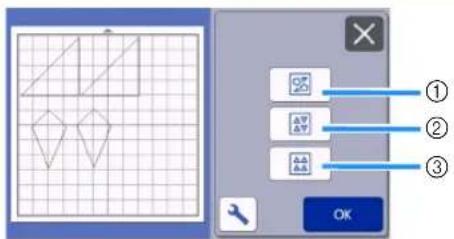
①Rearranging By Rotating Patterns to Any Angle This is useful when arranging a large number of patterns in a limited space.

②Rearranging By Rotating Patterns 0° or 180° This is useful when arranging the printed design (vertical patterns) on paper or fabric as the material for cutting/drawing or when using the vertical grain.

③Rearranging Without Rotating Patterns This is useful when arranging the printed design on paper or fabric as the material for cutting/drawing or when using the grain.
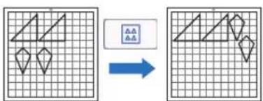
Scanning a Background Image
In this example, we will use material with a cutout in its upper-left corner as a background image.
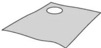

Memo
- The background scanning function is also useful when cutting out patterns from material with a design on it. By arranging the patterns on the screen in the desired patterned area of the material, cutouts with a specific design can be created.
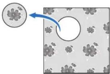
- This function cannot be used when an optional scanning mat is used.
- Depending on the machine model, the sizes of mats that can be used will differ. Check the "Maximum Scanning Area" under "Machine Information" of the settings screen. For details, refer to "Settings Screen" on page 10.
1 Attach the material for the background to the mat, and then press the operation panel.
For details on preparing the material and loading the mat, see "Loading the Mat" on page 29.
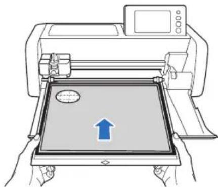
2 After selecting the cutting/drawing pattern, touch in the mat layout screen to start the background scanning function.

The following message appears.

3 Touch the "Start" key to start scanning.
▶ After the material has been scanned, it appears as the background in the mat layout screen.
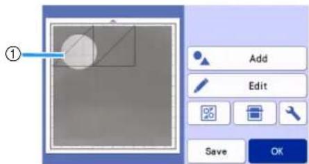
①Material with a cutout displayed as background
Memo
- If it is difficult to see the arranged patterns, adjust the background contrast in the settings screen. Touch in the mat layout screen to display the settings screen.
Background

: Makes the background image darker.
: Makes the background image lighter.
: Does not display the background image.
4 Touch the "Edit" key.

The mat editing screen appears.
Memo
- The pattern can also be moved by touching and dragging it in the screen.
5 Use the layout editing functions to move the patterns.
- For details on moving patterns, see "Layout Editing Functions" on page 46.
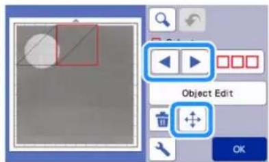
Memo
- The pattern can also be moved by touching the pattern(s) displayed in the layout editing screen and dragging it in the screen.
6 Check that the patterns in the screen do not overlap the cutouts in the background material and then touch the "OK" key.
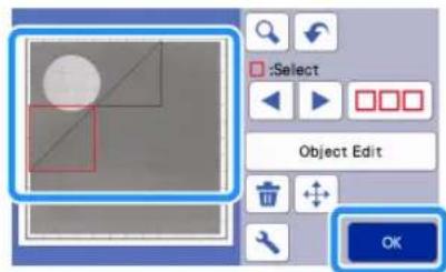
Memo
- When the scanned material is unloaded, the background is cleared.
Character Input Functions
Characters can be selected, edited, cut out and drawn as a single pattern. Select the character type from the pattern category selection screen.

①Select decorated characters. The characters can be edited, cut out and drawn as a pattern. For details on editing, see "Pattern Editing Functions" on page 44.
②Type in the desired combination of characters.
Typing In the Word "RAINBOW"
1 Select the font category in the pattern category selection screen.

2 Touch the desired font type.
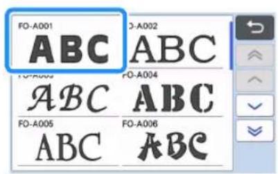
3 Type in the characters.
The keyboard is in the QWERTY layout. After entering the characters, touch the "OK" key.

①Character input display
②Character keys
③Uppercase/lowercase selection key
④Space key
⑤Letter/accented character/number selection key
⑥Backspace key (deletes one character from the end of those displayed)
⑦Cursor movement keys

- If the entered characters do not fit within the cutting/drawing area, the character size is automatically reduced.
4 Adjust the settings of character size and character spacing.
Touch or to adjust the character size or the space between characters. After completing the adjustment, touch the "Set" key.

①Character size adjustment keys

②Character spacing adjustment keys
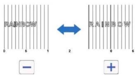
③Size of entire character string

Check the character arrangement.
To cut or draw, touch the "OK" key.
To save the characters as data, touch the "Save" key.
For details on saving data, see "Saving" on page 65.


Memo
- Entered characters can only be edited as the entire character string. One character cannot be edited individually.
DRAWING FUNCTIONS
With a pen and pen holder, you can draw patterns on material. Using the seam allowance settings also allows you to draw patterns with seam allowances on material and then cut them out. These drawing functions can be used to create quilt pieces.

■Preparation
Prepare the following accessories for drawing. An additional purchase may be required depending on the machine model.
- Pen holder
- Erasable pen set or color pen set
- Mat appropriate for the material that will be drawn on.
- Blade and blade holder appropriate for the material that will be cut.
- Mat, iron-on fabric appliqué contact sheet, or high tack adhesive fabric support sheet appropriate for the fabric that will be cut or drawn on.
Drawing
In this example, we will draw a built-in pattern on material.
■Preparing the Pen Holder
1 Press the button at the center of the pen holder to unhook the lid and open it.
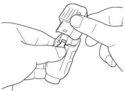
2 Remove the cap from the pen, and then insert the pen into the pen holder with the point down.
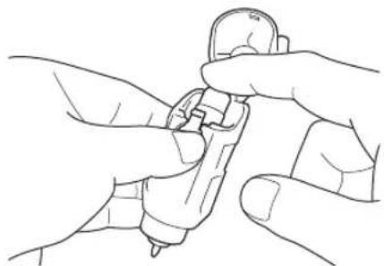
3 Close the lid of the pen holder.

• After use, remove the pen from the pen holder, and then attach the cap to the pen before storing it.
■Drawing
1 Grasp the holder grip, and then install the pen holder in the carriage with its lid opening button facing against you.
- For details, see "Installing and Uninstalling the Holder" on page 27.

2 Select and edit the pattern.
- For details on selecting and editing patterns, see "Selecting and Editing the First Pattern" on page 32.
3 Raise the scanner lever (on the left side of the machine) to "2".

4 Load the mat with the material for drawing (cutting) attached.
- Lightly insert the mat into the feed slot, and press

in the operation panel.
- For details on inserting the mat, see "Loading the Mat" on page 29.

5 Select "Draw" in the preview screen.

The drawing line (blue) appears.
6 Adjust the drawing speed and pressure.
Before drawing the pattern, adjust the drawing speed and pressure. These adjustments can be made from the
settings screen. Touch .
▶ Touch + or to change the settings.


Note
- If the drawing pressure is too high, the pen tip may be damaged. Adjust it to an appropriate setting.

Memo
- Adjustments to the drawing pressure will affect the finished product. Use the same material that the pattern will be drawn on to make the adjustments.
7 Touch the "Start" key to start drawing.

Note
• After use, remove the pen from the pen holder, and then attach the cap to the pen before storing it.
Cutting Around Drawings
In this example, we will specify a seam allowance for a built-in pattern and draw the pattern, then cut an outline around it.
■Specifying the Seam Allowance
1 Select the pattern to be drawn, and then touch the "Set" key.

The mat layout screen appears.
2 Touch the "Edit" key.
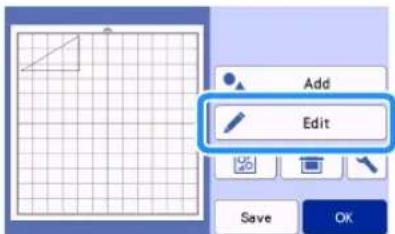
3 Touch the "Object Edit" key in the mat editing screen.


Touch

The Seam Allowance screen appears. If appears in gray, the seam allowance cannot be applied.


Memo
- Depending on the pattern, the seam allowance may be applied as a default. Check the setting.
The pattern in the preview appears with a drawing line (blue) and a cutting line (black).

Specify the seam allowance settings.

①Select whether or not to add a seam allowance.
②Specify the width (distance between the outline and cutting line) of the seam allowance. Touch


change setting.

①Seam allowance line
②Pattern outline (stitching line)
③Seam allowance
▶ Touch the "OK" key to finish specifying the setting and return to the object editing screen.
6 Touch the "OK" key in the object editing screen.
7 Touch the "OK" key to finish editing the pattern.
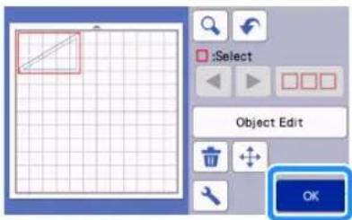

Memo
- To draw the seam allowance on the wrong side of the fabric, flip the pattern.
Image of Pattern Piece to be Created

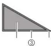
②④
①Right side of fabric
②Wrong side of fabric
③Drawing line (stitching line)
④Seam allowance line
After attaching to the mat the fabric with the wrong side facing up, load the mat into the machine, flip the pattern, and then draw it and cut it out.

①Wrong side of fabric
8 Check the pattern arrangement, and then touch the "OK" key.
When using fabric, the patterns may not be cleanly cut if they are arranged near the edge of the fabric. In this case, move patterns so they are at least 10 mm from the fabric edge (the edge of the cutting/drawing area in the screen).
- To re-edit the pattern arrangement after checking it, touch the "Edit" key. For details, see "Mat Layout Screen" on page 45.
- Select the "Cut Area" setting appropriate for the mat being used. (See page 10.)
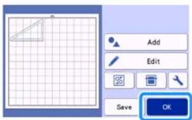
The preview screen appears.
■Loading the Material
Load the mat with the material for cutting (drawing) attached.
When drawing the seam allowance on the wrong side of the fabric, attach the material to the mat with its wrong side facing up.
- For details on attaching material to the mat, see "Attaching the Material to the Mat" on page 19.
- Lightly insert the mat into the feed slot, and press

in the operation panel.
- For details on inserting the mat, see "Loading the Mat" on page 29.
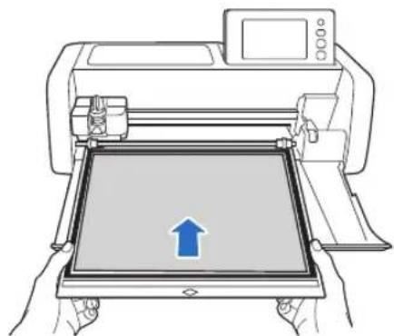
■Drawing
1 Select "Draw" in the preview screen.
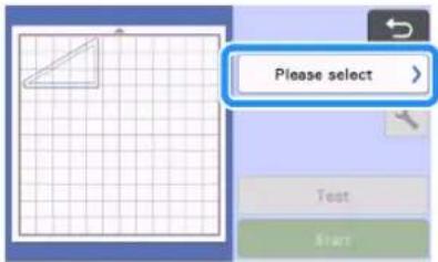
▶ A preview of the line to be drawn appears.

2 Adjust the drawing pressure.
For details on adjusting the drawing pressure, see step 6 (page 59) in "Drawing".
3 Touch the "Start" key to start drawing.
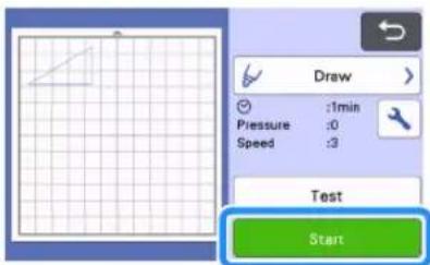
When drawing is finished, the message appears in the screen. After you touch the "OK" key, the preview screen appears.
- To perform test/trial drawing operations to adjust the drawing pressure, touch the "Test" key. For details, see "Test Cut (Trial Cut)" on page 28.
- To cut around the drawn patterns, keep the mat inserted into the slot without pressing and continue with the following cutting procedure.
Cutting
1 Select "Cut" in the preview screen.
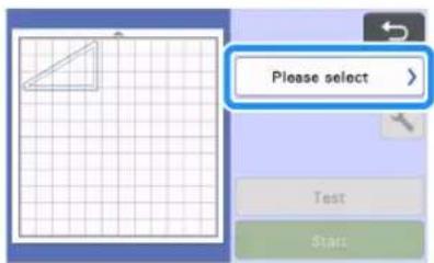
▶ A preview of the line to be cut appears.
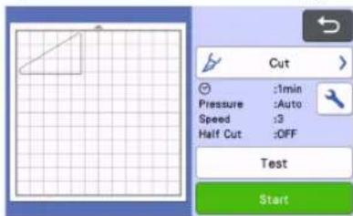
2 Remove the pen holder, and then install the blade holder.
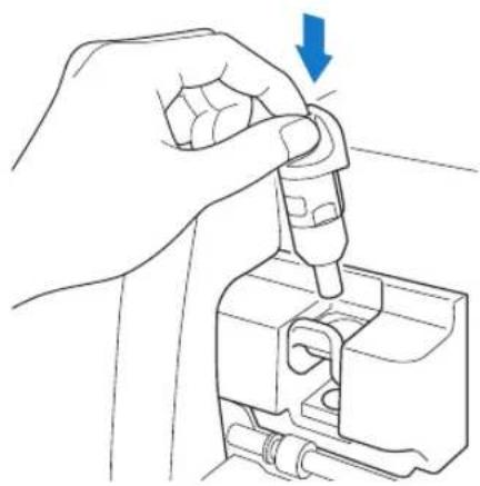

Note
• After use, remove the pen from the pen holder, and then attach the cap to the pen before storing it.
- Please remove protective cap from blade holder before placing it into the machine carriage.
WARNING
- This is not a toy and is not intended to be used by children. In order to prevent choking hazards, do not allow infants/children to put the protective caps in their mouths.
3 Touch the "Start" key to start cutting.
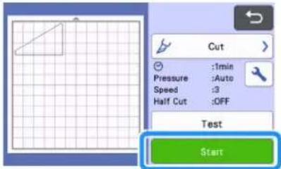
When cutting is finished, the preview screen appears.
4 Press in the operation panel to feed out the mat.
5 Peel the patterns off the mat.
- For details, see "Unloading the Mat" on page 30.
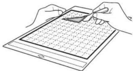
Using Drawing Functions to Fill Patterns/Make Outlines Thicker
☐ Precautions for Using the Fill Function
- Depending on the material and pen being used, material drawn with a filled pattern may be difficult to peel off or may tear. Perform test/trial drawing with the pattern to be used in your project.
●An open pattern cannot be filled. Example:

- When fill settings are specified, the settings are applied to all patterns in the pattern layout screen.
●Fill and additional line settings cannot both be specified for the same pattern.
■Filling Patterns
1 Touch in the object editing screen.

Settings screen
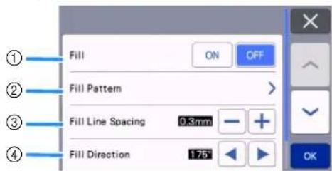
①Fill Select whether or not to fill patterns.
②Fill Pattern

③Fill Line Spacing
Adjust the spacing of the lines filling the pattern.
④Fill Direction
Adjust the direction of the fill pattern.
■Making Pattern Outlines Thicker
Additional lines can be drawn to make pattern outlines appear thicker.
1 Touch in the object editing screen to display the outline settings screen.

Settings screen

Note
- The settings for "Number of Additional Line" and "Additional Line Spacing" will not be applied to patterns with fill settings applied.
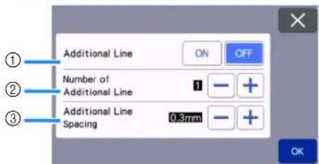
①Additional Line
Select whether or not lines are to be added.
②Number of Additional Line
Specify the number of lines to be added.
③Additional Line Spacing
Specify the spacing of the lines to be added.

Note
- Refer to the following examples when specifying settings for "Number of Additional Line" and "Additional Line Spacing".
①Number of Additional Line 1: One line added.
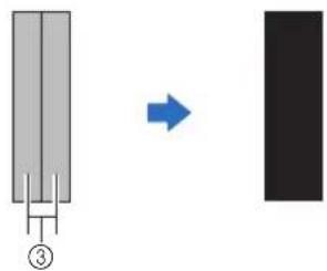
②Number of Additional Line 2: Two lines added.
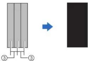
③Additional Line Spacing: Adjusts the line spacing. Increasing the line spacing creates a space between the lines.

Memo
- The drawing result differs depending on the thickness of the pen that is used. Make adjustments according to the pen thickness.
MEMORY FUNCTIONS
Patterns and characters arranged in the cutting/drawing area can be saved and recalled later.
☐ For details on the file formats that can be imported into the cutting machine from a USB flash drive or computer, see "Importing Designs" on page 67.
☐ If the name of the data file/folder cannot be identified, for example, when the name contains special characters, the file/folder is not displayed. If this occurs, change the name of the file/folder. We recommend using the 26 letters of the alphabet (uppercase and lowercase), the numbers 0 through 9, “-” and “_”.

Note
- USB flash drive is widely used, however some USB flash drive may not be usable with this machine. Please visit our website "http://s.brother/cpoac/ " for more details.
Saving
Available in the following screen
| Mat layout screen | →Tutorial 1; Step 6 (page 33) in “Selecting and Editing the Second Pattern” |
1 Touch the "Save" key to display the file destination options.
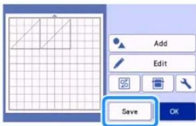
2 To save the data on a USB flash drive, insert the USB flash drive into the USB port (for a USB flash drive) on this machine.
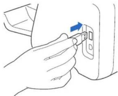
3 Touch the file location to save the file.
![graph LR A["①"] --> B["Printer"] C["②"] --> D["USB Device"] B --> E["③"] D --> E style A fill:#f9f,stroke:#333 style C fill:#f9f,stroke:#333 style D fill:#f9f,stroke:#333](/content/2026/05/937368/images/3137bc1f27bbfdb06517cd1bf79ec2d6003b90db141e0061a329d446805c4114.jpg)
①Save to the machine's memory.
When saving is finished, the following message and the name of the saved file appear.

②Save to the USB flash drive.
When saving is finished, the following message and the name of the saved file appear.
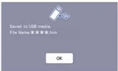
- The name of the saved file with the extension ".fcm" is automatically assigned.

Note
- While data is being saved, do not remove the USB flash drive.
③Save to CanvasWorkspace.
- Use the wireless network function transfer patterns to CanvasWorkspace. This function is only available when the machine's wireless network settings and machine registration on CanvasWorkspace have been completed. For details about setting methods, refer to "WIRELESS NETWORK CONNECTION FUNCTION" on page 86.
- Transferrable data can only be sent to CanvasWorkspace one file at a time.
When saving is finished, the following message appears. For details on checking data saved in CanvasWorkspace, refer to the Help for CanvasWorkspace.

4 Touch the "OK" key to finish saving the data.
Retrieve Data
1 Touch the "Retrieve Data" key in the home screen to display the retrieve source selection screen.
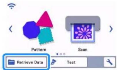
2 To use the data from a USB flash drive, insert the USB flash drive into the USB port (for a USB flash drive) on this machine.
3 Touch where you saved the pattern to be retrieved, and then select the pattern.
![graph TD A["①"] --> B["②"] B --> C["③"] C --> D["④"] D --> E["④"] style A fill:#f9f,stroke:#333 style B fill:#ccf,stroke:#333 style C fill:#cfc,stroke:#333 style D fill:#fcc,stroke:#333](/content/2026/05/937368/images/93f8d41b36e7628a9b481a46484f435db57d2dd237d7cf76750ff0971225d4ce.jpg)
①Retrieve from machine's memory key
②Retrieve from USB flash drive key
③Retrieve from dedicated application key (via a wireless network connection)
④Retrieve from CanvasWorkspace key (using a USB cable)
Memo
- The patterns for the optional roll feeder can be retrieved from "Roll Feeder" in the home screen.
①Retrieve from the machine's memory.
▶ Touch the pattern to be retrieved and display.
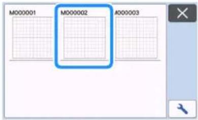
②Retrieve from a USB flash drive.
- If there are folders on the USB flash drive, touch a folder to display the list of patterns that it contains.
- If there are many folders or patterns, touch the arrows keys in the screen to scroll up or down.

Memo
- It may take some time for the USB flash drive to be detected. Wait 5 to 6 seconds after inserting the USB flash drive before pressing a key. (The length of time differs depending on the USB flash drive.)
- When using a USB flash drive with an access indicator, wait until the indicator stops flashing.
- If an error is indicated, touch

▶ Touch the pattern to be retrieved and display.

Memo
- When retrieving pattern data from the machine's memory or a USB flash drive, the size of the thumbnail previews can be changed.
Touch to display the settings screen, and
then touch or to change the size.

③Retrieve from dedicated application (via a wireless network connection).
The transferred pattern from dedicated application appears on mat layout screen. For details, see "Retrieve Transferred Patterns from CanvasWorkspace (Using a Wireless Network)" on page 93 or "Retrieve Transferred Patterns from Artspira (Using a Wireless Network)" on page 96.
④Retrieve from CanvasWorkspace (using a USB cable).
The transferred pattern from CanvasWorkspace appears on mat layout screen. For details, see "Retrieve Transferred Patterns from CanvasWorkspace (Using a USB Cable) (compatible only with Windows)" on page 94.
4 Check the preview of the pattern layout in the screen, and then touch the "OK" key.
![graph TD A["Grid with diagonal line"] --> B["Zoom Icon"] B --> C["OK"] C --> D["④"] C --> E["③"] C --> F["②"] C --> G["①"]](/content/2026/05/937368/images/6e5d5cf34f24c11cae8c4c0902fc8ccccc50b04f9694898ae41a3a507a6d946a.jpg)
①Returning Key
Touch to return to the list of patterns at the destination.
②Magnifying Key
Touch to display the patterns in zoom mode.
③Deleting Key
Touch to delete the data for the displayed pattern layout.
④OK Key
Touch to recall the pattern layout data.

Memo
- Even if a seam allowance has been saved with the pattern(s) (see “Cutting Around Drawings” on page 59), the “Seam Allowance” setting specified in the settings screen will have priority and will be applied. If necessary, adjust the “Seam Allowance” setting in the settings screen (see “Seam Allowance” on page 11).
Importing Designs
■Importable File Formats
In addition to the FCM format, files in the following formats can be imported into the machine.
- Embroidery data in PHC/PHX/PES format (compatible models and via USB flash drive only): For details, see page 98.
- SVG (Scalable Vector Graphics: vector image format for describing two-dimensional graphics) format. “.svg” data is displayed in the pattern list screen by file name (the actual image cannot be displayed).

Memo
- The imported vector graphics will appear in the edit screen after they have been converted. This feature allows you to import only vector data. Image, text, width of the line, gradient, opacity, and any other styles or attributes of line will not be imported.

Chapter 4 SCANNING FUNCTIONS
SCANNING FOR CUTTING (Direct Cut)
A printed image (paper/sticker), stamped paper or an original hand-drawn illustration can be scanned and its outline can be cut out or drawn. This is useful for scanning images for paper crafts, then cutting them out.

Tutorial 4 - Scanning and Cutting
In this tutorial, we will scan an illustration drawn on paper, then cut around it.

■Preparation
1 Prepare the original.

When using the "Direct Cut" mode, use originals like those described below.
- Patterns that are clearly drawn, with no gradation, fading or blurriness
• Not using an extremely intricate design





2 Press to turn on the machine.
- For details, see "Turning On/Off the Machine" on page 8.
3 Install the cutting blade holder into the carriage of the machine.
- For details, see "Installing and Uninstalling the Holder" on page 27.
Scanning
Depending on the color of the illustration, it can be scanned in grayscale or color recognition mode.
1 Touch the "Scan" key in the home screen to select the scanning mode.

2 Select "Direct Cut" in the scanning mode selection screen.
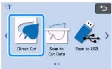
A message appears.
3 In the selection screen for the cutting data destination, touch .

4 Select the scanning mode according to the material to be scanned.
- First, test with grayscale recognition mode. If the desired cutting data is not created, test with color recognition mode.
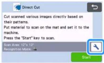

①Grayscale recognition mode
The cutting data is created after the illustration is converted to grayscale.
Scanning in grayscale recognition mode is most appropriate for illustrations with clear outlines or distinct brightness differences. Processing is faster with this mode compared with the color recognition mode.
If there are adjacent objects of the same color after an illustration has been converted to grayscale, select the color recognition mode.
Examples of illustrations appropriate for grayscale recognition mode:
| Example Result | ||
| Outlines that are clear |  |  |
| Distinct difference in brightness between background and illustration |  | |

Memo
- The edges of illustrations in a color of the same brightness as their background, as shown below, cannot be detected. In this case, use the color recognition mode.

①Background and illustration in colors with the same brightness.
②Color recognition mode
The cutting data is created without converting the illustration to grayscale. Creating data in this mode may take longer, depending on the pattern.
* The default scanning recognition setting is the grayscale recognition mode.
Examples of illustrations appropriate for color recognition mode:
| Example Result | ||
| Illustrations that are the same light color as the background |  |  |
| Illustrations that are the same dark color as the background |  | |
③Scanning area
The scanning size settings screen appears. The size of the scanning area can be selected. The available scanning area sizes differ depending on the model.
5 Attach the original that will be scanned to the mat.


Memo
- In "Direct Cut" mode, the scanning mat cannot be used.
- Depending on the machine model, the sizes of mats that can be used will differ. Check the "Maximum Scanning Area" under "Machine Information" of the settings screen (page 12).
- Before attaching the material to the mat, use a corner of the adhesive side of the mat to test attaching it.
6 While holding the mat level and lightly inserting it under the feed rollers on the left and right sides of the feed slot, press the operation panel.
- For details, see "Loading the Mat" on page 29.
7 Touch the "Start" key to start scanning.

Note
- When the scanner lever is raised, the following message appears.

Scanning with the lever raised may result in blurry scans.
■Creating Cutting Data
The procedure for creating cutting data differs depending on the mode.
□ Grayscale recognition mode
1 Check the scanned image, and then touch the "OK" key.
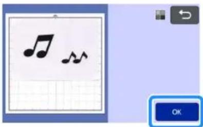
2 In the image trim screen, use the touch pen to drag to trim the image to the size to be imported.
- When trimming is performed, the "OK" key changes to the "Preview" key.
If cutting lines are created, the outline of the scanned illustration will be black.

①Image Detection Level Key Adjust the image detection level.
② Ignore Object Size Key Small unnecessary patterns (dotted lines, etc.) can be excluded from cutting data. For details, see "Specifying "Ignore Object Size" on page 80.
③Smoothing Setting Key Specify the level of smoothing applied to the image outline. For details, see “Adjusting Image Detection Levels” on page 80.
3 Touch the "Preview" key to confirm the trimmed area.

▶ Only the cutting lines appear.
4 Touch the "OK" key in the mat layout screen.

- Touch the "Edit" key to fill patterns or make outlines thicker. For details, see "Using Drawing Functions to Fill Patterns/Make Outlines Thicker" on page 63. In addition, a pattern can be deleted, or multiple patterns can be selected. For details on selecting multiple patterns, see "Selecting Multiple Patterns" on page 42.
- Touch or to edit the imported cutting data. For details, see "Advanced Cutting Functions for "Direct Cut" on page 72.
5 Select "Cut" in the preview screen.
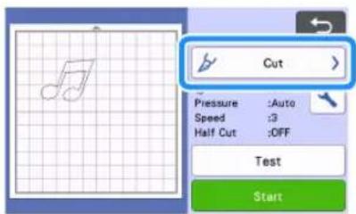
6 Touch the "Start" key to start cutting.
- For details on unloading the mat after cutting, follow the procedure under "Unloading the Mat" on page 30.

□ Color recognition mode
In the image trim screen, use the touch pen to drag to trim the image to the size to be imported, and then touch the "OK" key.

Memo
- Trimming the image to the desired size can reduce the amount of time required to convert it to cutting data.
2 Check the imported image in the image editing screen.
The created cutting data appears as black lines.

①Image Detection Level Key
If the cutting lines were not correctly detected, change the number of colors to be detected. If a color that appears as a single color is detected as separate colors, reduce the number of colors. If adjacent colors with a similar brightness are detected as a single color, increase the number of colors.
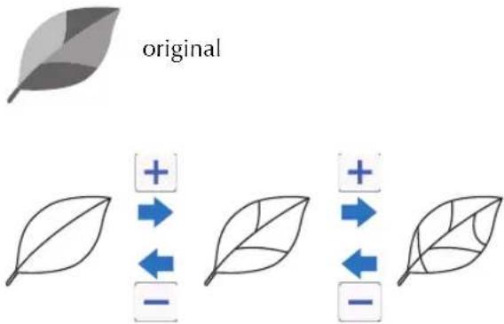
②Ignore Object Size Key
Small unnecessary patterns (dotted lines, etc.) can be excluded from cutting data. For details, see "Specifying "Ignore Object Size" on page 80.
③Smoothing Setting Key
Specify the level of smoothing applied to the image outline. For details, see "Adjusting Image Detection Levels" on page 80.
④OK Key
Touch the "OK" key to apply the settings. When trimming is performed, the "OK" key changes to the "Preview" key. After trimming, touch the "Preview" key to check the trimming results.

Memo
- When making a stamp, for example, the image may not be converted to cutting data if it contains a gradation or areas that are only partially filled with a color.
3 Touch the "OK" key.

- Touch or to edit the imported cutting data. For details, see "Advanced Cutting Functions for "Direct Cut" on page 72.
- Touch the "Edit" key to fill patterns or make outlines thicker. For details, see "Using Drawing Functions to Fill Patterns/Make Outlines Thicker" on page 63. In addition, a pattern can be deleted, or multiple patterns can be selected. For details on selecting multiple patterns, see "Selecting Multiple Patterns" on page 42.
▶ Only the cutting lines appear.
4 Select "Cut" in the preview screen.

5 Touch the "Start" key to start cutting.
- For details on unloading the mat after cutting, follow the procedure under "Unloading the Mat" on page 30.
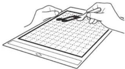
Advanced Cutting Functions for "Direct Cut"
■Outline Distance
Use this function to cut while adding a margin around patterns. Specify the distance from the cutting line to the outline of the scanned image.

①Pattern outline
②Cutting line
③Outline distance
Available in the following screen
| Mat layout screen | →Tutorial 4; Step 4 (page 71) in “Grayscale recognition mode” or Step 3 (page 72) in “Color recognition mode” |

Touch


The setting screen appears.

Touch

to change the setting.
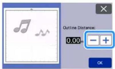


Outlining and Framing
Any shape can be specified as the cutting line for the scanned image.
Available in the following screen
| Mat layout screen | →Tutorial 4; Step 4 (page 71) in “Grayscale recognition mode” or Step 3 (page 72) in “Color recognition mode” |

Touch

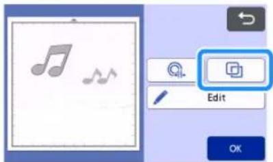
The settings screen appears.

Select the shape of the cutting line.

①Outlining
Touch this key to create a cutting line that follows the outline of the scanned image.

②Framing
Touch the key for the desired frame to add it to the scanned image and create a cutting line that follows its shape.
- If there are multiple images, a frame can be specified for each image.
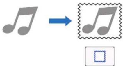
③Previewing
Display a preview of the image together with the cutting line for the selected frame.
CREATING CUTTING DATA (Scan to Cut Data)
A printed pattern or image or an original hand-drawn illustration can be scanned, converted to cutting lines for cutting/drawing with this machine, then saved as data.

Tutorial 5 - Creating Cutting Data
In this tutorial, we will save an illustration drawn on paper as cutting data.

■Preparing the material
When using the "Scan to Cut Data" mode, use originals like those described below.
- Patterns that are clearly drawn, with no gradation, fading or blurriness
• Not using an extremely intricate design



Scanning
1 Touch the "Scan" key in the home screen to select the scanning mode.

2 Select "Scan to Cut Data" in the scanning mode selection screen.

A message appears.
3 Touch, select the scanning mode, and then touch the "OK" key.
- First, test with grayscale recognition mode. If the desired cutting data is not created, test with color recognition mode.


①Grayscale recognition mode
The cutting data is created after the illustration is converted to grayscale. Scanning in grayscale recognition mode is most appropriate for illustrations with clear outlines or distinct brightness differences. Processing is faster with this mode compared with the color recognition mode.
If there are adjacent objects of the same color after an illustration has been converted to grayscale, select the color recognition mode.
②Color recognition mode
The cutting data is created without converting the illustration to grayscale.
Creating data in this mode may take some time.
* The default color recognition setting is the grayscale recognition mode.
Examples of illustrations appropriate for recognition mode:
| Example | Recommended recognition mode | |
| Outlines that are clear |  | Grayscale recognition mode |
 | ||
| • Distinct difference in brightness between background and illustration• Different brightness of adjacent colors |  | |
| • Similar brightness of adjacent colors |  | Color recognition mode |

Memo
- The edges of adjacent colors with the same brightness, as shown below, cannot be detected. In this case, use the color recognition mode.

①“a” and “b” as well as “c” and “d” have the same brightness.
③Scanning area
The scanning size settings screen appears. The size of the scanning area can be selected. The available scanning area sizes differ depending on the model.
4 Attach the original to the mat, and then load the mat into the feed slot.
- Lightly insert the mat into the feed slot, and press in

the operation panel.
- For details on loading the mat, see "Loading the Mat" on page 29.

Memo
- Depending on the machine model, the sizes of mats that can be used will differ. Check the "Maximum Scanning Area" under "Machine Information" of the settings screen (page 12).
5 Touch the "Start" key to start scanning.
- When the scanner lever is raised, a confirmation message appears. For details, see step 7 in "Scanning" of "Tutorial 4 - Scanning and Cutting" on page 68.
When scanning is finished, the scanned image appears in the screen.
■Creating Cutting Data
The procedure for creating cutting data differs depending on the mode.
□ Grayscale recognition mode
1 Select the cutting line type in the image editing screen.
The image shape is detected and cutting lines are created based on one of three standards. For this example, touch to create cutting lines using region detection.

①Outline detection
If you wish to cut/draw along the outline of an image, select this option to convert the outline of the image to a cutting line. This is useful for saving as data an illustration drawn for an appliqué.
②Region detection
Select this option to detect the colored portions of an image as regions and create a cutting line around each region. Cutouts can be created using thick hand-drawn lines, such as borderlines of images or text illustrations. This option allows you to use not only cut-out patterns but the material from which portions are cut out, such as lace.
③Line detection (Grayscale recognition mode only)
Select this option to detect the center of lines and convert them to a cutting line. This is useful for detecting patterns consisting of multiple pieces and creating cutting lines for each piece.

Memo
- Lines thicker than 1.5 mm will not be detected as lines.
Difference in cutting lines depending on detection standard
Example 1
| 1 Outline detection | 2 Region detection | 3 Line detection | |
| Original |  | ||
| Cutting lines |  |  |  |
| Finished project after cutting |  |  |  |
Example 2
| 1 Outline detection | 2 Region detection | 3 Line detection | |
| Original |  | ||
| Cutting lines |  |  | Does not apply since there are no outlines for each color in the original. |
| Finished project after cutting |  |  | |
2 Use the touch pen (stylus) to touch and drag it around the screen to trim the cutting lines.
- When trimming is performed, the "OK" key changes to the "Preview" key. Touch the "Preview" key to confirm the trimmed area.

①Image Detection Level Key
Adjust the image detection level.
②Ignore Object Size Key
Small unnecessary patterns (dotted lines, etc.) can be excluded from cutting data. For details, see "Specifying "Ignore Object Size" on page 80.
③Smoothing Setting Key
Specify the level of smoothing applied to the image outline. For details, see "Adjusting Image Detection Levels" on page 80.
□ Color recognition mode
In the image trim screen, use the touch pen to drag to trim the image to the size to be imported.
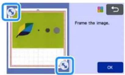

Memo
- Trimming the image to the desired size can reduce the amount of time required to convert it to cutting data.
2 Touch the "OK" key to confirm the trimmed area.

3 Select the detection standard in the image editing screen.
The image shape is detected and cutting lines are created based on one of two standards. For this
example, touch to create cutting lines using region detection.
For details on the detection standards, see step 1 in "Grayscale recognition mode".

①Outline Detection Key
②Region Detection Key
Difference in cutting lines depending on detection standard
| 1 Outline detection 2 Region detection | ||
| Original |  | |
| Cutting lines |  |  |
| Finished project after cutting |  |  |
③Image Detection Level Key
If the cutting lines were not correctly detected, change the number of colors to be detected. If a color that appears as a single color is detected as separate colors, reduce the number of colors. If adjacent colors with a similar brightness are detected as a single color, increase the number of colors.
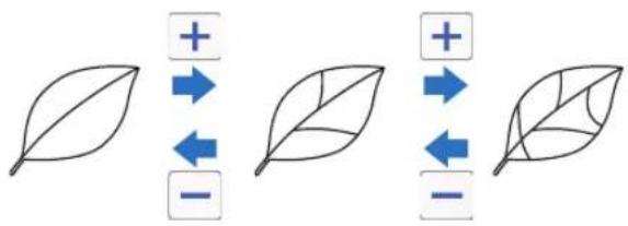
④Ignore Object Size Key
Small unnecessary patterns (dotted lines, etc.) can be excluded from cutting data. For details, see "Specifying "Ignore Object Size" on page 80.
⑤Smoothing Setting Key
Specify the level of smoothing applied to the image outline. For details, see "Specifying Smoothing" on page 81.
⑥OK Key
Touch the "OK" key to apply the settings. When the number of colors is changed, the "OK" key changes to the "Preview" key. After changing the number of colors, touch the "Preview" key to check the results.

Memo
- When making a stamp, for example, the image may not be converted to cutting data if it contains a gradation or areas that are only partially filled with a color.
Saving Data
1 Select the destination where the data will be saved.
Select the desired location. For this example, select the machine.
![graph LR A["①"] --> B["Printer"] C["②"] --> D["USB Device"] B --> E["Laptop"] D --> E E --> F["Wireless Interface"]](/content/2026/05/937368/images/53ea67dff3464eb54e722fcfc2bb3dc2b8816a1b38a303a89d1e127de8517a1f.jpg)
①Save to the machine's memory.
②Save to the USB flash drive.
③Transfer to CanvasWorkspace.
▶ Touching a key starts saving the data. When the data has been saved, the following message appears.

2 Touch the "OK" key to finish saving the data.
3 Press in the operation panel to feed out the mat, and then peel off the original from the mat.
■Retrieve Cutting Data
Saved cutting data can be retrieved for cutting.
1 Attach the material for cutting to the mat, and then load the mat.
- For details on attaching the material, see "Attaching the Material to the Mat" on page 19.
- For details on loading the mat, see "Loading the Mat" on page 29.
2 Retrieve the saved cutting data.
- For details on retrieve data, follow the procedure under "Retrieve Data" on page 66.

▶ A preview of the pattern layout appears.
3 Edit the cutting data as necessary, and then cut or draw.
For details on finishing cutting, follow the procedures under "Loading the Mat" on page 29 and "Cutting" on page 29.
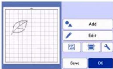


Memo
- Small spots and unwanted lines created during scanning can be deleted after a scanned image is converted to cutting data.
After recalling the cutting data into the mat layout screen, use the editing functions for selecting the spots to delete.
For details on the function, see "Specifying the Selection Area" on page 43.

①Touch for selecting multiple patterns in the specified area.
②Unwanted spots and lines
Specify the area of the unwanted spots, and then touch the "OK" key.

▶ Touch to delete all of the selected spots.

Adjusting Image Detection Levels
The output levels of the scanned image data can be adjusted.
Available in the following screen
| Image editing screen | →Tutorial 5; Step 1 (page 76) in “Grayscale recognition mode” or Step 3 (page 77) in “Color recognition mode” |
■Specifying "Ignore Object Size"
Small unnecessary patterns (dotted lines, etc.) can be excluded from cutting data. In the following example, we will scan three images of different sizes (4 mm, 40 mm and 100 mm) and use the grayscale recognition mode of the "Scan to Cut Data" mode.
1 Select one of the detection options, and then touch "Ignore Object Size" to display the setting screen.
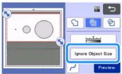
2 Specify an object size smaller than which is not to be converted to cutting lines.
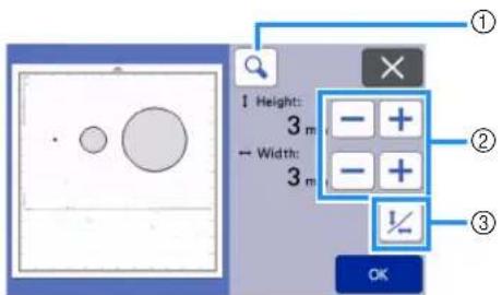
①Magnifying
②Size Adjustment Keys
③Locking/Unlocking the Aspect Ratio
![graph LR A["1"] --> B["2"] B --> C["1"] style A fill:#f9f,stroke:#333 style B fill:#bbf,stroke:#333 style C fill:#dfd,stroke:#333](/content/2026/05/937368/images/1d028ff2b73c048aaecca5e2216a91df5d273e9293db1f4066fd789a0aad3723.jpg)
①Cutting line created
② No cutting line created
▶ Touch the "OK" key to apply the settings. Touch
✗ to return to the previous screen without applying the settings.
■Setting Image Detection Level (Grayscale recognition mode only)
Convert an image with a gradation or shading to a two-tone (black and white) image, and then create cutting lines for that image. The image detection level (threshold) can be specified.
In the following example, we will scan three images of different tones (light, medium, dark).
1 Touch in the function selection screen to display the setting screen.

2 Specify the threshold for converting an image to a two-tone image using and.

![graph TD A["1"] --> B["2"] C["1"] --> D["2"] E["1"] --> F["2"] G["1"] --> H["2"] I["1"] --> J["2"] K["1"] --> L["2"] M["1"] --> N["2"] O["1"] --> P["2"] Q["1"] --> R["2"] S["1"] --> T["2"] U["1"] --> V["2"] W["1"] --> X["2"] Y["1"] --> Z["2"] AA["1"] --> AB["2"] AC["1"] --> AD["2"] AE["1"] --> AF["2…](/content/2026/05/937368/images/d8e41ed222243485c5467d2d3c5993732603bc68eb0e65dd17e479c67a885b22.jpg)
① Cutting line created
② No cutting line created
▶ Touch the "OK" key to apply the settings. Touch
✗ to return to the previous screen without applying the settings.
■Specifying Smoothing
Curves and corners in the image can be smoothed out.
1 Touch in the function selection screen to display the smoothing setting screen.

2 Touch or to specify the setting.
- Four settings are available: OFF, Low, Middle and High. Setting to "Low" is suitable for smoothing the corner and straight line.


OFF Middle
SCANNING IMAGES (Scan to USB)
A pattern printed on paper or fabric, an image, a pattern template or an original hand-drawn illustration can be scanned and saved as image data on a USB flash drive. This is useful for saving the data of an original image as backup before cutting.
Notes on Scanning
■Scanning Specifications
- Scanning format: Color
- Saved file format: jpg
■Material That Can be Scanned
| Thickness | Max. 3 mm |
| Type | Paper/Fabric |
| Mat | Mat suitable for the material (See “Reference Table of Mat, Blade and Material Combinations” on page 16.) |

Memo
- Depending on the machine model, the sizes of mats that can be used will differ. Check the "Maximum Scanning Area" under "Machine Information" of the settings screen (page 12).
- Optional scanning mat can be used without attaching the material as the scanning mat can secure the material by inserting the material between the sheet and the mat.
Tutorial 6 - Scanning to USB
In this tutorial, we will save an illustration drawn on paper as JPEG data to a USB flash drive.
■Scan Settings
1 Insert the USB flash drive into the USB port (for a USB flash drive) on this machine.

2 Touch the "Scan" key in the home screen to select the scanning mode.
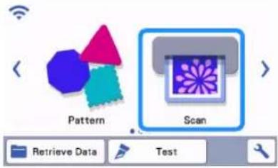
3 Select "Scan to USB" in the scanning mode selection screen.

A message appears.
4 Touch to display the scanning settings screen.
Specify the size of the area to be scanned and the scanning resolution.
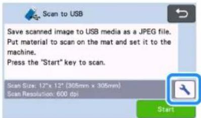
5 Touch the "Scan Size" button to display the scanning size settings screen.
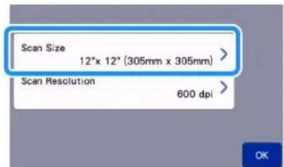
6 Select the size of the scanning area.
From the list, touch the key for the size of the original to be scanned. For this example, select the A4 size.

①Size selection keys
②Touch to cancel the setting and return to the previous screen.
③Touch to scroll through the list.
After the selected key is highlighted, touch the "OK" key to finish specifying settings.
- Select "Custom", and then touch the "OK" key to specify the desired scanning area. For details, see "Selecting the Area to be Saved" on page 84.
7 Touch the "Scan Resolution" button to display the scanning resolution settings screen.

8 Select the scanning resolution.
From the list, touch the key for the scanning resolution. For this example, select 400 dpi.

①Resolution selection keys
②Touch to cancel the setting and return to the previous screen.
After the selected key is highlighted, touch the "OK" key to finish specifying settings.
9 Check the settings, and then touch the "OK" key.

A message appears.
■Scanning and Saving
1 Attach the original that will be scanned to the mat.


- Place the original to be scanned so that it is in the landscape orientation.

①12" × 12" (305 mm × 305 mm)
②Letter (216 mm × 279 mm)
③A4 (210 mm × 297 mm)
④8" × 8" (203 mm × 203 mm)
⑤5" × 7" (127 mm × 178 mm)
⑥4" × 6" (102 mm × 152 mm)
⑦3.5" × 5" (89 mm × 127 mm)
2 Load the mat into the feed slot.
For details on loading the mat, see "Loading the Mat" on page 29.
3 Touch the "Start" key to start scanning.
- When the scanner lever is raised, a confirmation message appears. For details, see step 7 in "Scanning" of "Tutorial 4 - Scanning and Cutting" on page 68.
The data is saved at the same time that the original is being scanned.
When scanning and saving is finished, the completion message appears.
4 Touch the "OK" key to exit "Scan to USB" mode.
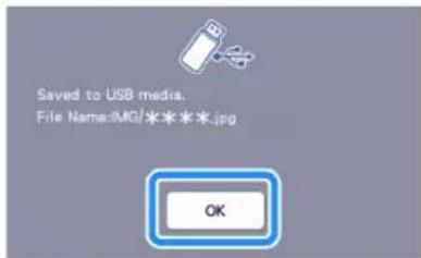
5 Press in the operation panel to feed out the mat.
6 Remove the USB flash drive from the USB port (for a USB flash drive) on this machine.
7 From a computer, check the saved image data.
Selecting the Area to be Saved
When saving a scanned image to a USB flash drive, the desired scanning area can be specified.
1 Follow steps 1 through 5 in "Scan Settings" of "Tutorial 6 - Scanning to USB" on page 82.
2 Select "Custom", and then touch the "OK" key.
3 Using the touch pen (stylus), drag to select the scanning area, and then touch the "OK" key.

- The scanning area (white area) can also be dragged to move it.

Memo
- Load the mat with the original to be scanned attached, and then touch to display the mat in the screen. The scanning area can be selected while viewing the displayed image.
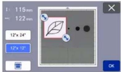
- On models compatible with 24-inch scanning, the mat size key ( ) appears. (Touch a mat size key ( or2") to " 12" x 12" specify a mat size of 12" x 12" (305 mm x305 mm) or 12" x 24" (305 mm x 610 mm).)
4 Continue from step 7 in "Scan Settings" of "Tutorial 6 - Scanning to USB".
Transferring an Image to CanvasWorkspace
An image scanned with the machine can be sent to CanvasWorkspace. This is useful for saving data or editing the image in CanvasWorkspace.
1 Select "Transfer to CanvasWorkspace" in the scanning mode selection screen.

2 Touch to display the scanning settings screen.

3 Touch the "Scan Area" button to display the scanning area settings screen.

4 Select the size of the scanning area.
After the selected key is highlighted, touch the "OK" key to finish specifying settings.
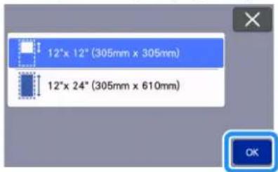
5 Attach the material to be scanned onto the mat.
6 While holding the mat level, lightly insert it into
the feed slot, and then press the operation panel.
- For details, see "Loading the Mat" on page 29.
7 Touch the "Start" key to start scanning.
- When the scanner lever is raised, a confirmation message appears.
For details, see step 7 in "Scanning" of "Tutorial 4 - Scanning and Cutting" on page 68.
For details on checking data saved in CanvasWorkspace, refer to the Help for CanvasWorkspace.
Chapter 5 WIRELESS NETWORK CONNECTION FUNCTION
Machine Wireless Network Connection Settings
This machine is equipped with a wireless network connection function. For the method for setting the wireless network connection, see the following explanation.
-
Enable the machine's wireless network function and connect to the internet.
-
Register the machine on CanvasWorkspace.
* When using CanvasWorkspace, a CanvasWorkspace login ID is required. If you don't have a free account, perform a new registration from http://CanvasWorkspace.Brother.com.
Enable the Wireless Network Function
1 Turn on the machine.
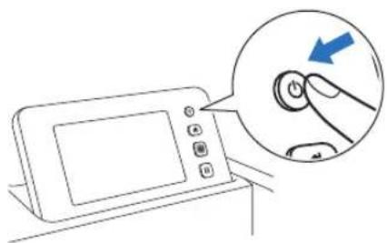
When the following message appears, touch the "OK" key.

2 Touch or in the home screen.

The network settings screen appears.
Memo
- Another way to access the "Network" menu is to click located at the bottom of the home screen.
- is displayed by default. Follow the on-screen instructions to proceed to the network settings screen.
3 Select "ON" for "WLAN Enable".

Your machine will begin to emit the wireless network signal.
Memo
- Another way to turn "ON" the "WLAN Enable" is by selecting "Yes" when the message below appears in the "Setup Wizard".

Set up the Wireless Network
Wireless LAN connection can be set up by using the wizard (recommended) or alternative method.
■Requirements for the wireless network connection
The wireless network connection complies with IEEE 802.11 n/g/b standards and uses the 2.4 GHz frequency.
Memo
- A wireless network cannot be set up with WPA/WPA2 Enterprise. For the authentication methods your machine supports, see "Err-03" on page 118.
■Connect Using Setup Wizard (Recommended)
1 The Wireless Network Name (SSID) & Network Password (KEY)* are required to connect your machine to a wireless network.
* Network Password is also described as the Network Key, Security Key, or Encryption Key.
| Network Name (SSID) | Network Password(Network Key) |

Note
- If you do not know this information (Network Name (SSID) and Network Password (Key)), you cannot continue the wireless setup.
• How can I find this information?
1) You should see the documentation provided with your wireless access point/router.
2) The default Network Name (SSID) could be the manufacturer's name or the model name.
3) If you do not know the security information, please consult the router manufacturer, your system administrator, or internet provider.
4) Some Wireless Network Name (SSID) and Network Password (Key) are case (upper case and lower case) sensitive. Please properly record your information.
2 Touch or in the home screen.

The network settings screen appears.

Memo
- Another way to access the "Network" menu is to click located at the bottom of the home screen.
- is displayed by default. Follow the on-screen instructions to proceed to the network settings screen.
3 Under "Network" settings screen as shown below, touch "Setup Wizard".

Available Network Name (SSID) will be displayed.
4 Select your Network Name (SSID), and then touch the "OK" key.

The screen for entering the Network Password (Key) appears.

Note
- If the desired Network Name (SSID) is not displayed, specify it as described below. 1) Select "[New SSID]", and then touch the "OK" key. * "[New SSID]" appears at the bottom of the list of detected SSIDs.
![SSID of access point HAGISOL [Saved SSID] [New SSID]](/content/2026/05/937368/images/37bb61e6db47306d4699a0c7a2aef292c3d0c40b21c66a3fb4605c9665d4eb18.jpg)
2) Type in the desired Network Name (SSID), and then touch the "OK" key. 3) Specify the authentication method and encryption mode and then touch the "OK" key.

Memo
- appears beside a previously connected network from the list of available networks. Since the Network Password (Key) has been saved for the network beside a connection to that network can be re-established without having to re-enter the connection information (Network Password, etc.). - The previously entered Network Password (Key) for a maximum of 12 connections are saved with "[Saved SSID]". Touch the "[Saved SSID]" key to display the connection information.
5 Type in the Network Password (Key) noted in step 1, and then touch the "OK" key.

①Character input display
②Character keys
③Uppercase/lowercase selection key
④Space key
⑤Letter/number/special character selection key
⑥Backspace key (Deletes the character at the cursor's position.)
⑦Cursor keys (Move the cursor to the left or right.)
6 When the message shown below appears, touch the "Yes" key.
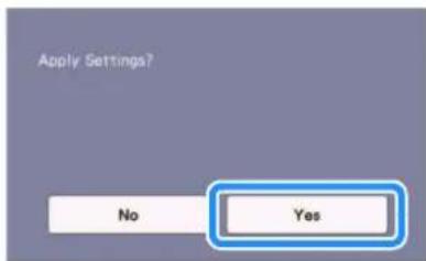
The following screen appears when a connection is established.
Touch the "Next" key, and then continue with "Register Machine Under CanvasWorkspace" on page 90.
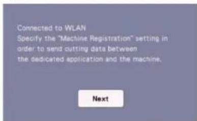

Memo
- If you have already completed the machine registration under CanvasWorkspace, the following screen appears. Touch the "OK" key to complete the wireless network setup.
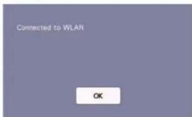

Note
- If a connection was not successfully established:
- If the message "Wrong Network Key: Err-04" appeared, the Network Password (Key) may have been entered incorrectly. Touch the "OK" key, and then repeat the procedure from step 3 of "Connect Using Setup Wizard (Recommended)" on page 87.
- For details on other causes, see page 117.
- While connected, the strength of the signal is
indicated by the blue icon in the upper-left corner of screens such as the home screen.

Strong signal

Medium signal

Weak signal

No signal
- After your wireless network has been set up, your machine will connect to the wireless network each time the machine is turned on. However, "WLAN Enable" in the network settings screen must remain set to "ON".
■Connect Using "WLAN Assistant Wizard" (WAW).
The wireless network can be set up using the dedicated application "WLAN Assistant Wizard" (WAW). Download the application from http://s.brother/cuoad/, and then follow the instructions that appear in the computer screen in order to complete the setup.
After a connection is established, touch the "Next" key, and then continue with "Register Machine Under CanvasWorkspace" on page 90.
Check the Wireless Network Setup/Status
Follow these instructions when you can't establish the wireless network connection.
1 Under "Network" settings screen as shown below, touch "WLAN Status".

The wireless network connection status, protocol, signal strength and Network Name (SSID) are displayed.
![WLAN Status ① Status Active (11g) ② Signal Medium 36Mbps [10Ch] ③ SSID SNC_TEST ④ Comm. Mode Infrastructure](/content/2026/05/937368/images/03c00b983dd8f51b67be164b71d86eddece32a7559cf037ca2d8ab6c1589efbb.jpg)
①Displays the connection status. When "Active (xxx)" is indicated: The machine is connected to a wireless network. The characters within the parentheses indicate the protocol of the wireless network being used.
When "Connection Fail: Err-xx" is indicated: The machine failed to establish a connection. "Err-xx" indicates the error number. See error codes on page 117.
②Displays the wireless signal strength; communication speed and channel being used.
③Displays the Network Name (SSID).
④Displays the communication mode. The communication mode is fixed to the infrastructure mode.
Using the "Others" Menu
The "Others" menu is at the bottom of the network settings screen.

The "Others" menu contains the following items.

①TCP/IP can be manually entered.
②Displays the MAC address.
③All applied network settings will be reset to manufacturers original settings when the machine was purchased. Any information you inputted will be removed (erased). After setting this function, turn the machine off, then on again.
④Use this when proxy settings are required.
Register Machine Under CanvasWorkspace
Once you have registered your machine under CanvasWorkspace, you can now transfer data to and from CanvasWorkspace and your machine.
This section describes the procedure for linking a machine with a specific number to a CanvasWorkspace login ID.
If the setup is not completed correctly and an error message appears, see error codes and error messages on page 115.

Note
- A computer that is connected to the network and can run CanvasWorkspace is required.
- Before continuing with this procedure, setup for the connection between your machine and wireless network must be completed. If your machine is not connected to the network, first follow the procedure in “Machine Wireless Network Connection Settings” on page 86.
In the following procedures, [MACHINE] indicates operations performed from your machine, and [COMPUTER] indicates operations performed in CanvasWorkspace.
[MACHINE]
The following screen message will appear after the wireless network connection setup, touch the "Register" key.

①App Guide key
![BROTHER ScanNCut SDX330D - [MACHINE] - 2](/content/2026/05/937368/images/c2dcd58494e5d83f0b7c095fff6551bbf9e85e92c6564f36d2ccd7c05b75a694.jpg)
Memo
- Press the App Guide key to display app instructions related to the machine.
- If the connection is interrupted after the wireless network connection has been set up, the machine can be registered with “Machine Registration” in the settings screen.
2 After the following screen, describing how to obtain the PIN code, appears, leave the screen displayed, and then continue with the next [COMPUTER] operation.

①Machine number

Note
- Do not touch the "OK" key yet. Your machine number appearing in the screen will be used in the following step.
[COMPUTER]
The screens in the following descriptions are those that appear when CanvasWorkspace is opened on a computer.
3 Open CanvasWorkspace Internet version (http://CanvasWorkspace.Brother.com) on your computer and then log in.
![BROTHER ScanNCut SDX330D - [COMPUTER] - 1](/content/2026/05/937368/images/9556d07d917b9a019b7f67cc3686e75a513589d90566aba61f6406a190f2dab9.jpg)
Note
- First time users should obtain a free account.
- If you already have an account with CanvasWorkspace, you can use the same login ID and password to login.
4 Click in the upper-right corner of the screen.
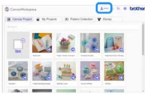
The page for managing your account appears.
5 Click "Machine(s) Registration".

6 Click "Register a New Machine".
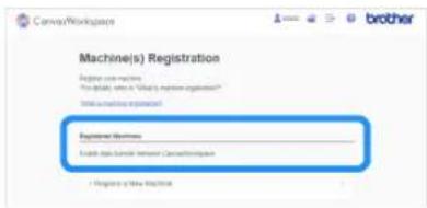
Note
- If the maximum amount of registered machines has been reached, select the registered machine that you are not using and click "Remove" in the "Registered Machine Information" screen, and then register the new machine.

7 Type in your machine number, and then click the "OK" button.
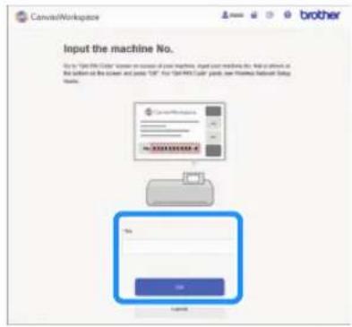
Memo
- Your machine number appears on your machine in the screen shown in step 2 describing how to obtain the PIN code.
A four-digit PIN code appears in the screen.
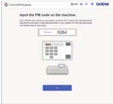
[MACHINE]
8 Touch the "OK" key.
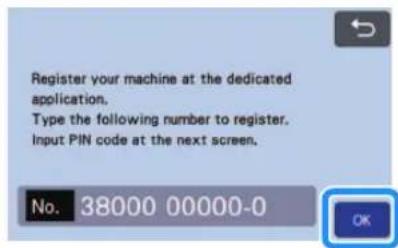
The PIN code input screen appears.
9 Type in the four-digit PIN code that appeared in the CanvasWorkspace screen, and then touch the "OK" key.

The following screen appears.
10 Touch the "OK" key.
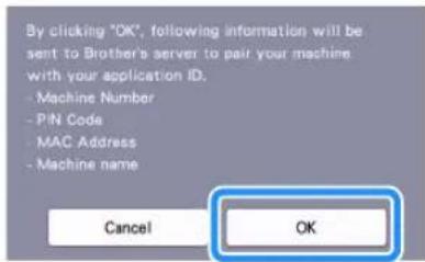
The machine information is transferred to the server.
11 Touch the "OK" key.

The account registration screen appears.

①Login ID linked to your machine
②Touch this key to link your machine with a different login ID. Then perform the registration operation again, referring to "Register Machine Under CanvasWorkspace" on page 90.
③Touch this key to delete the currently linked login ID. For the detail, refer to "Deleting the linked login ID" on page 92.
This completes the registration of your machine with CanvasWorkspace.

Note
- If an error occurs while transferring data, refer to "ERROR MESSAGES" on page 115.
For details on transferring data between CanvasWorkspace and your machine, refer to "Transferring an Image to CanvasWorkspace" on page 84.
■Deleting the linked login ID
To completely delete a linked login ID from the machine, follow the procedure below.

Touch

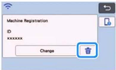

Touch the "OK" key.

The login ID is deleted, and the following screen appears.


Memo
- Touch the "Register" key to register your machine again.
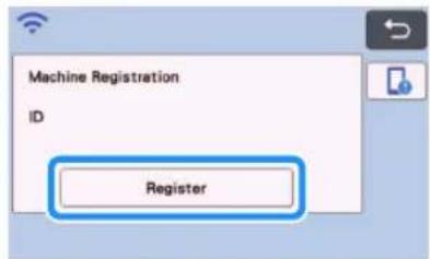


For details on the procedure, refer to "Register Machine Under CanvasWorkspace" on page 90.
Chapter 6 DATA TRANSFER FUNCTION
Retrieving Data from Application
This product can retrieve data from CanvasWorkspace and Artspira.
CanvasWorkspace is a free pattern editing application with both PC (Windows/Mac) and Web versions available. The downloadable PC (Windows/Mac) version allows you to authenticate many optional kits, and is equipped with more useful editing functions than the Web version. The Web version can be used without need for installation.
Artspira is a cloud based mobile app where you can transfer designs with WLAN connected machines.
CanvasWorkspace (Windows/Mac): Downloadable from the Brother support website (http://s.brother/cuoad/).
CanvasWorkspace (Web): http://CanvasWorkspace.Brother.com/
Artspira : Downloadable from the Brother support website (http://s.brother/csyai/).
Retrieve Transferred Patterns from CanvasWorkspace (Using a Wireless Network)
Perform the wireless network settings for the machine and register the machine on CanvasWorkspace ahead of time. For details, refer to "WIRELESS NETWORK CONNECTION FUNCTION" on page 86.
1 Create and edit data in CanvasWorkspace (Windows/Mac).
- For detailed methods for editing patterns in CanvasWorkspace, refer to the Help for CanvasWorkspace.
2 From the [File] menu, click [Export/Transfer FCM File].

3 Click [Transfer FCM File via the Internet].

When the pattern is transferred to the machine, the following message appears. Click [OK].

Note
- Data is transferred to the machine through the server. Data on the server is deleted after a certain period of time has passed.
- Only one data item can be transferred to the machine. If the transferred data already exists, it is updated.
Memo
- For CanvasWorkspace (Web), click [Download] and then [ScanNCut Transfer] to send the FCM file to the machine.
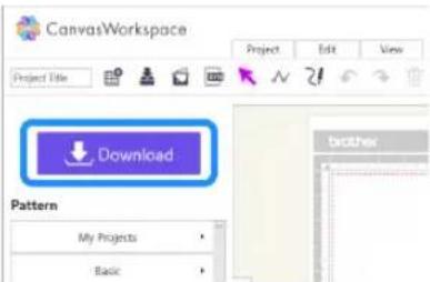

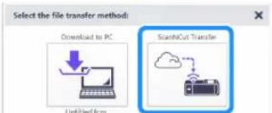
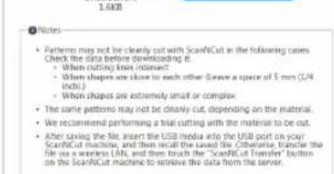
4 Touch the "Retrieve Data" key in the home screen to display the retrieve source selection screen.
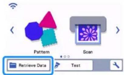
5 Select

The mat layout screen appears.
Retrieve Transferred Patterns from CanvasWorkspace (Using a USB Cable) (compatible only with Windows)
When the machine is connected to the computer with a USB cable, a pattern can be retrieved from CanvasWorkspace (Windows).
■Connecting Your Machine to the Computer
- Compatible models:
IBM PC with a USB port as standard equipment IBM PC-compatible computer equipped with a USB port as standard equipment - Compatible operating systems:
Microsoft Windows 8.1, Windows 10 (except Windows 10 S mode)
■USB Cable (Sold Separately)
- We recommend using a USB 2.0 cable (Type A/B) that is no longer than 2 meters (6 feet).
■Transferable File Formats
- FCM files opened in CanvasWorkspace
1 Insert the USB cable connector into the corresponding USB ports for the computer and for the machine.
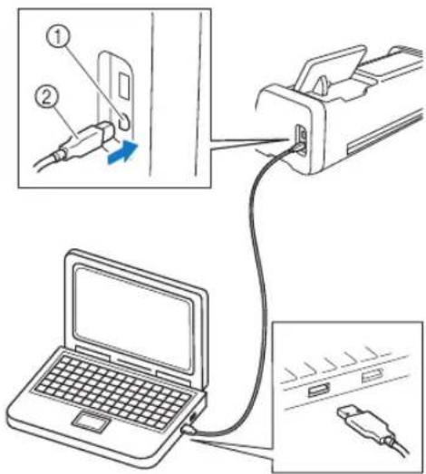
①USB port for computer
②USB cable connector

Note
- The connectors on the USB cable can only be inserted into a port in one direction. If it is difficult to insert the connector, do not insert it with force. Check the orientation of the connector.
1 Create and edit data in CanvasWorkspace.
2 From the [File] menu, click [Export/Transfer FCM File].
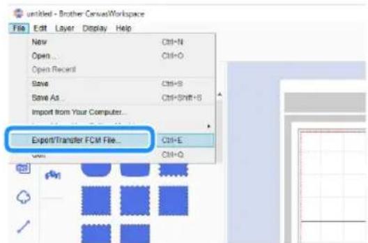
3 Click [Transfer FCM File to ScanNCut DX via USB Cable].

When the pattern data is saved to the machine, the following message appears. Click [OK].

Note
- Only one pattern data can be transferred to the machine. If data had already been transferred to the machine, it will be overwritten.
4 Touch the "Retrieve Data" key to display the recall source selection screen.

5 Select

The mat layout screen appears.
Batch Download a Pattern Collection from CanvasWorkspace (compatible only with the Web version)
A feature has been added to CanvasWorkspace (Web), allowing you to batch-download optional pattern collections that have been activated. Save the downloaded patterns to a USB flash drive, and retrieve patterns in each collection from the "My Collection" category on the machine.

Memo
The batch download function on the [Pattern Collection] and [Disney] tabs displayed in the following applications cannot be used.
- CanvasWorkspace (Windows/Mac)
- CanvasWorkspace (Web) accessed from a mobile device
1 Log in to CanvasWorkspace. (http://CanvasWorkspace.Brother.com)
2 From the [Pattern Collection] or [Disney] tab in the main screen, select the category to be batch-downloaded.

3 Click in the upper-right corner of the screen, and then download the ZIP file.

4 Expand the downloaded ZIP file, and then save the folder to a USB flash drive.

Memo
- Save the expanded folder directly to the USB flash drive.
- Save the folder without changing its name or contents.
5 Insert the USB flash drive into the machine.
6 Touch in the home screen to display the following screen.

7 Select "My Collection".
▶ A folder for each pattern collection appears.


Memo
- To retrieve a roll feeder patterns, select "Roll Feeder", shown below.
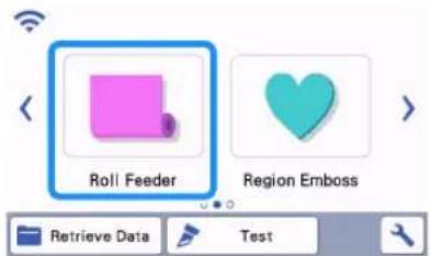
8 Select the pattern collection folder.
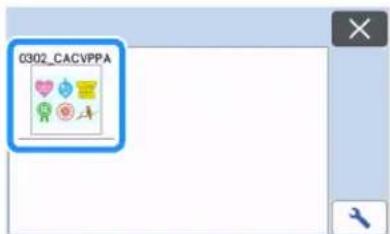
The patterns in the folder appear.
9 Select the pattern to be retrieved.
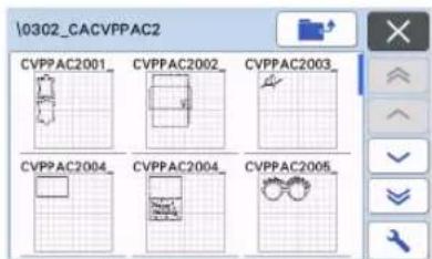
Retrieve Transferred Patterns from Artspira (Using a Wireless Network)
Perform the wireless network settings for the machine and register the machine ahead of time.
If you have already registered your machine under CanvasWorkspace, you don't need to register under Artspira App.
For details how to use the Artspira App, refer to "Artspira App Quick Guide"(https://s.brother/csyai/).

Memo
- (If your screen has CanvasWorkspace login button) Login with the CanvasWorkspace ID and password.
- (If your screen does not have CanvasWorkspace login button) Login with any other ID and set the CanvasWorkspace linkage in Artspira app setting screen to inherit the machine registration setting in CanvasWorkspace.
My Connection Function
This product is equipped with a function for linking with Brother embroidery machines (compatible models only).
Using the wireless network function, you can transfer built-in patterns from the cutting machine, or make an outline of part of an embroidery pattern from the embroidery machine and transfer it to cut or draw with the cutting machine.
For a detailed explanation using patterns, refer to the "My Connection" operation manual. http://s.brother/cmoae/
- For details on compatible machines, check the Brother support website (http://s.brother/cnxaa/).
- Of the built-in patterns in the machine, some of copyrighted patterns cannot be transferred.
■Preparation
Perform the wireless network settings for the machine and register the machine under CanvasWorkspace ahead of time. For details, refer to "WIRELESS NETWORK CONNECTION FUNCTION" on page 86. For details on wireless network settings for the embroidery machine, refer to the embroidery machine's instruction manual.
Retrieving Embroidery Data for Cutting (Compatible Models Only)
Embroidery data (.phc, .phx or .pes files) can be retrieved to the machine, then cut out or drawn. .phc or .phx files are embroidery data from embroidery machines equipped with an embroidering function, and .pes files are embroidery data created with the embroidery design software system PE-DESIGN. With this embroidery data, outline data or region data of parts of each color or of the entire pattern can be created.

Memo
- This feature is compatible only with models equipped with a function to import embroidery data. For the functions available with your machine model, check “Embroidery Data (.PES/.PHC/.PHX)” under “Machine Information” of the settings screen.
Preparing .phc, .phx or .pes Files
■.phc Files, .phx Files
Using an embroidery machine that can save embroidery patterns to an external device, save the embroidery pattern to the USB flash drive. The procedure for saving the embroidery pattern to the USB flash drive differs depending on the embroidery machine. Refer to the operation manual for your embroidery machine.
When using an embroidery machine equipped with a connection function, it is possible to transfer .phx files using the wireless network function.
For details, see the "My Connection" operation manual.
■. pes Files
Using embroidery design software system, save the embroidery pattern to the USB flash drive. The procedure for saving the embroidery pattern to the USB flash drive differs depending on the version of the software. Refer to the instruction manual for your software. This manual uses embroidery patterns created with PE-DESIGN as examples.

Note
- For details on .phc, .phx and .pes files, contact your authorized Brother dealer or the nearest Brother authorized service center.
Retrieving the Pattern to the Cutting Machine
1 Retrieve the embroidery pattern (.phc, .phx or .pes file) from the USB flash drive to the machine. (Refer to "Retrieve Data" on page 66.)
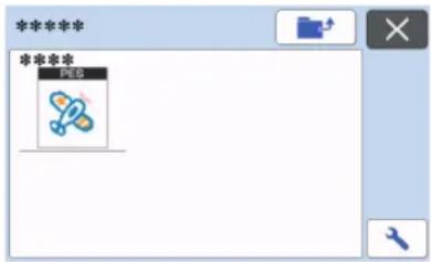
- .phc, .phx and .pes files cannot be imported into CanvasWorkspace. Retrieve the patterns directly from a USB flash drive to the cutting machine.
▶ A confirmation screen appears.
![graph TD A["Start"] --> B{Password: ****} B -->|①| C["Check for Security"] B -->|②| D["Restore Security"] B -->|③| E["Secure Security"] B -->|④| F["Update Security"] B --> G["Security"] style A fill:#f9f,stroke:#333 style B fill:#ccf,stroke:#333](/content/2026/05/937368/images/283eba777a114da0304fb7d42c04451a79f9bc3dd7f80cf8127cec96b6496712.jpg)
①Magnifying
Zoom in on the pattern to 200%. Then, touch to display the patterns enlarged by 400%. To scroll through the screen, touch the arrow keys.
②Deleting
Delete the selected patterns.
③Appliqué
Create cutting data for an appliqué piece.
④Embroidering lines
Convert embroidery data to cutting/drawing data.

Note
- With embroidery data created from a photo, intricate shapes are not suitable for cutting. Use the Enhanced Image Tracing function (premium function) of CanvasWorkspace to extract the necessary outlines from the original photo.
Creating Appliqué Data

Memo
- Make sure that the pattern contains an "APPLIQUE MATERIAL" pattern.
1 Touch to display the pattern piece list screen, and then touch the "OK" key.

The pattern editing screen appears.

①Duplicating
Create a duplicate of the pattern. For details, see "Pattern Editing Functions" on page 44.
②Outline Distance
Specify the distance from the outline of the pattern to the cutting line. For details, see "Advanced Cutting Functions for "Direct Cut" on page 72.
③Settings
Specify the measurement units (millimeters or inches), cutting area and pattern spacing. For details, see "Settings Screen" on page 10.
2 Touch the "Set" key to display the mat layout screen.
- The pattern can be edited. For details, see "Mat Layout Screen" on page 45 or "Layout Editing Functions" on page 46.
3 Touch the "OK" key.

"APPLIQUE MATERIAL" appears in the screen.
4 Attach the fabric for the appliqué piece to the mat, and then cut out the pattern.
5 Refer to the operation manual for the embroidery machine to complete the appliqué.
Creating Embroidering Line Data
1 Touch to display the pattern editing screen, and then touch the "OK" key.
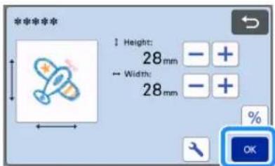
- The pattern size can be adjusted in this screen. For details, see "Pattern Editing Functions" on page 44.
2 In the part selection screen, select the color recognition mode.
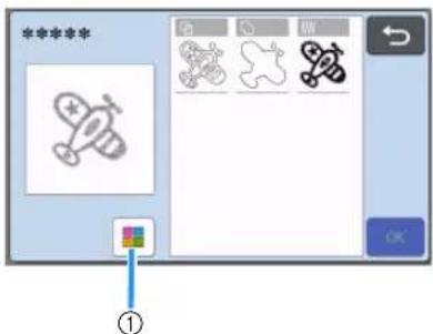
①Switch on and off color recognition mode.
• Color recognition mode switched off The cutting/drawing data is created after the embroidery pattern is converted to grayscale.

①Region detection
Select this option to detect the colored portions of a pattern as regions and create a cutting/drawing lines around each region.
②Outline detection
Select this option to convert the outline of the image to cutting/drawing lines.
③Stitching line detection
Select this option to convert the stitching lines embroidered by the machine to cutting/drawing lines.
Stitching line detection is not suitable for cutting since the needle movements of the embroidery machine are faithfully converted to data. We recommend using this option for drawing and line embossing (premium function).
Differences in cutting/drawing lines depending on detection method (color recognition mode switched off)
| : Region detection |  Outline detection Outline detection |  Stitching line detection Stitching line detection | |
| Original image |  |  | |
| Cutting/drawing lines |  |  |  |
| Finished project after cutting/drawing |  |  |  |
• Color recognition mode switched on Each color in the embroidery pattern is detected to create cutting data.

①The parts for each color detected as a region are displayed in the list.
②Region detection
③Outline detection
Differences in cutting/drawing lines depending on detection method (color recognition mode switched on)
| : Region detection | : Outline detection | |
| Original image |  | |
| Cutting/drawing lines |  |  |
| Finished project after cutting/drawing |  |  |
3 Select the detection method, and then touch the "OK" key.

4 Adjust the cutting/drawing lines.
After making the desired adjustments, touch the "Set" key.
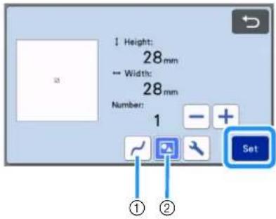
①Smoothing
Smooths out curves and corners in the lines. Select from the four settings available: OFF, Low, Middle and High.
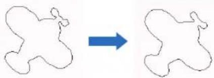
OFF Middle
②Grouping/Ungrouping
When ungrouped, the parts can be edited separately. For details, see "Grouping/ Ungrouping Patterns" on page 48. The setting cannot be changed if there is only one shape.

Memo
- If the pattern contains unnecessary parts, ungroup it. This allows the unnecessary parts to easily be deleted in the mat layout screen, which appears next.
5 In the mat layout screen, check the cutting/drawing lines.
- The pattern can be edited. For details, see "Mat Layout Screen" on page 45 or "Layout Editing Functions" on page 46. After finishing all editing, touch the "OK" key.

CONSUMABLES
Replacement Criteria
For the safe operation of this machine, replace the following consumables according to the replacement criteria. To purchase parts, contact the retailer who sold you this machine or the nearest authorized service center. For details on the optional accessories, see "OPTIONAL ACCESSORIES" on page 123.
Mat
- When the mat's adhesive strength decreases
- When there are many cutting traces in the mat
- When there is a deep cut from cutting in the mat
Cutting blade
- When the cuts in the material become rough, reducing the quality of the finished product
- When the cutting edge becomes blunt
- When the blade is chipped (If the Cut Pressure setting value is increased and you are still having issues cutting evenly, the blade may be chipped and will need to be replaced.)
High tack adhesive fabric support sheet
- When the sheet's adhesive strength decreases
- When fabric attached becomes twisted while being cut
Scanning mat
- When the mat and cover sheet become dirty, reducing the quality of the scan image
Erasable pen
- When the ink is dry and not marking the fabric properly
- When the ink is used completely
Color pen
- When the ink is dry and not marking the paper or material properly
- When the ink is used completely
Replacing the Blade
■Removing
1 Twist off the holder cap to remove it.
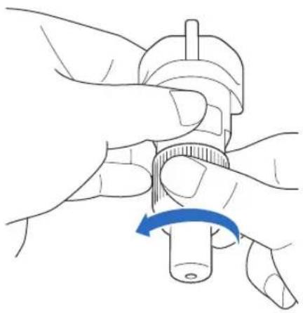
For the rotary auto blade holder, proceed to step ③.
2 Stick the blade straight into the rubber area on the back of the included spatula.

①Rubber area
3 Pull up the holder to leave the blade in the rubber area.

③(For Rotary Auto Blade Holder) Hold the shaft section of the rotary auto blade, and remove it from the holder.

CAUTION
- When removing the rotary auto blade, do not touch the blade. Be sure to hold the shaft while removing it. There is a risk of injury.
Installing
1 Grasp the shaft of the new blade, and then insert it into the blade slot in the end of the holder.
The blade shaft is held in place by a magnet in the holder. Slowly insert the blade shaft, and then slowly release it after the shaft snaps into place against the magnet.
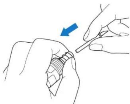
2 Twist on the holder cap to attach it to the holder.
Fully tighten the cap until it can no longer be turned.


Note
- When attaching the holder cap, be careful not to bump the blade edge against the holder cap.
- Please remove protective cap from blade holder before placing it into the machine carriage.
WARNING
- This is not a toy and is not intended to be used by children. In order to prevent choking hazards, do not allow infants/children to put the protective cap in their mouths.
CAUTION
• After removing the blade holder from the machine, be sure to attach the protective cap.
- Do not press the tip of the holder with your hand or fingers because the tip of the blade will extend and may result in injuries.
- Do not touch the tip of the blade with your hands or fingers. There is a risk of injury.
- This is not a toy and is not intended to be used by children. In order to prevent injury, do not allow infants/children to touch the blade.
Cleaning
■Cleaning the Mat
Cuttings and cut edges of patterns attached to the mat may reduce the mat's adhesive strength and prevent correct operation. Periodically clean the mat. Using the included spatula, lightly scrape off any cuttings attached to the mat. Strongly rubbing the adhesive side of the mat may damage it.

Use tweezers (available either as optional accessories or commercially) to remove any fabric threads attached to the mat.
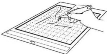
Clean the dotted marks on the mat and their surrounding area with a dry cloth.


Note
- Do not use alcohol or water to clean the mat.
- When the mat is not being used, clean it, and then store it with the protective sheet affixed. If the protective sheet is not affixed, the mat's adhesive strength will decrease. At that time, do not affix the protective sheet while the mat is damp. Otherwise, the mat's adhesive strength will decrease.
- Do not fold or bend the mat to store it.
- Store the mat at room temperature and in a location not exposed to high temperatures, high humidity or direct sunlight.
- If the mat no longer has any adhesive strength, replace it with a new one. For details on optional mats, see "OPTIONAL ACCESSORIES" on page 123.
■Cleaning the Holder
If material cuttings, lint or dust accumulate in the holder, it may not operate correctly. Clean the holder after every use.

Twist off the holder cap to remove it.
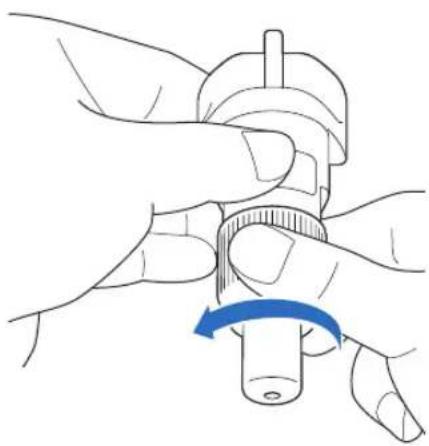
2 Using a commercially available brush, clean off cuttings, lint and dust.
Specifically, clean the surface of the blade and the cutting scraps or shavings in the spaces. If lint and dust accumulate between the blade and holder, the blade may no longer rotate or the cutting quality may become poor. In addition, clean out any lint and dust that has accumulated in the cap.


Note
- Clean so as to avoid bumping the blade edge against anything hard, such as metal.

CAUTION
- Do not touch the tip of the blade with your hands or fingers. There is a risk of injury.
3 Attach the holder cap to the holder.
For details on attaching the holder cap, see "Installing" on page 103.
■Cleaning Inside the Machine
If there are vertical lines or blank areas in the scanned image, lint or dust may have accumulated in the machine. The lint may also attach to the surface of the feed rollers, preventing a mat to be loaded or unloaded correctly. Use a soft brush to clean it.
1 Turn off the machine, unplug the power cord from the electrical outlet, and then disconnect the AC power cord from the AC power jack on the back of the machine.

2 Open the front tray cover.
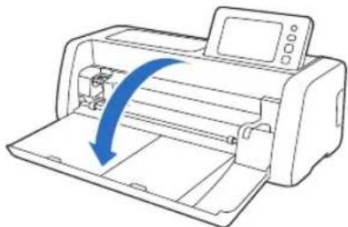
3 Remove the holder from the carriage.

4 Use a commercially available brush to clean around the feed slot and the carriage.

Cleaning the Scanner Glass
If there are unwanted vertical lines in the scanned image or if scanning cannot be done cleanly, the scanning area of the scanner may have become dirty. Clean the scanner glass inside the machine.
1 Turn off the machine, unplug the power cord from the electrical outlet, and then disconnect the AC power cord from the AC power jack on the back of the machine.
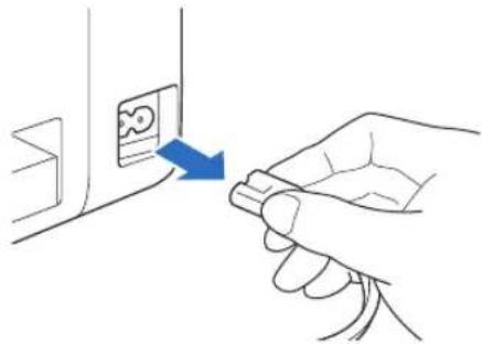
2 Store away the operation panel.

3 Turn the machine upside down, and then pull out the rear tray.

4 Pull the rear tray release lever (at the bottom of the machine), and then remove the cover.
Pull out the rear tray to remove it together with the cover.
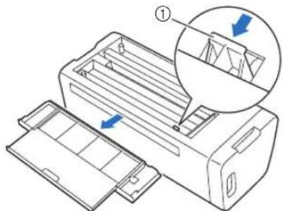
①Rear tray release lever
5 Dampen a soft lint-free cloth with water and firmly wring it out, and then wipe the scanner glass inside the machine.

6 Attach the cover to the machine.
- Push in the cover until it snaps into place.

7 Push in the rear tray.
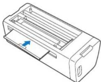
8 After cleaning, perform a test scan.
Adjusting the Screen
If the screen does not respond correctly when you touch a key (the machine does not perform the operation or performs a different operation), follow the steps below to make the proper adjustments.
1 Holding your finger on the LCD screen, turn the main power to off and back to on. Keep your finger on the LCD screen, until Brother logo disappears.

The touch panel adjustment screen is displayed.
2 Using the included touch pen (stylus), lightly touch the center of each +, in order from 1 to 5. If an error occur when touching +, start again from number 1.
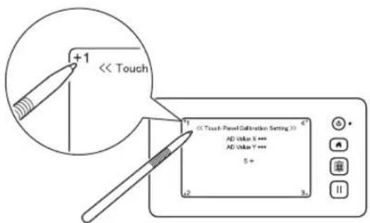
After completing the touch panel adjustment, the message "SUCCESS" appears on the screen.
3 Turn the main power to off, then turn it back to on.

Note
- If you finish the screen adjustment and the screen still does not respond correctly, or if you cannot do the adjustment, contact the retailer who sold you this machine or the nearest authorized service center.
Adjusting the Scanning/Cutting Position
In "Direct Cut" mode, the cutting position can be automatically adjusted if it has shifted.
For details on the "Direct Cut" mode, see "SCANNING FOR CUTTING (Direct Cut)" on page 68.
■Materials
| Paper | Thick paperColor: WhiteSize: A4 size (210 mm × 297 mm) or Letter size (216 mm × 279 mm)Thickness: 0.2 to 0.3 mm(recommended) |
| Mat | Mat suitable for the material (See page 16.) |
| Cutting blade | Auto Blade Holder (black) |

Memo
- Be sure to first test attach it to a mat suitable for the paper.
1 Insert the holder into the carriage.
- For details, follow the procedures under "Installing and Uninstalling the Holder" on page 27.
2 Attach the paper to the mat.
- Align the upper-left corner of the paper with the upper-left corner of the mat.
- For details on attaching the paper, follow the procedure under "Attaching the Material (Paper)" on page 19.

①Long side
②Short side
3 Touch the "Scanning/Cutting Position Adjustment" button in the settings screen.

The following message appears.
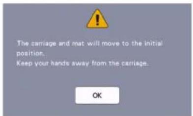
- Touch the "OK" key.
4 Press to feed in the mat.
- For details, see "Loading the Mat" on page 29.

5 After making sure that the scanner lever (on the left side of the machine) is lowered to "1", touch the "Start" key to start cutting.
See "Cutting" on page 29.
▶ Position adjustment cuts are cut, and then the cuts are scanned.


- Using the intersecting cuts on the left and right sides, the scanning position is automatically adjusted.
6 The adjustment results screen appears.

- If the center of the cut aligns with the center of the red circle, the position is properly adjusted. Touch the "Yes" key, and then continue with step 7.
- If the center of the cut does not align with the center of the red circle, the position is improperly adjusted. Touch the "No" key, replace the paper attached to the mat, and then repeat steps through ⑤ to readjust the position.
7 When the following message appears, touch the "OK" key.
The adjustment is finished.

- To return the settings to their defaults, touch the "Reset" key in the screen shown below.
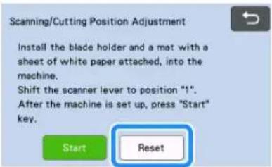
8 Use "Direct Cut" mode to check the adjustment results.
- For details on the "Direct Cut" mode, see "SCANNING FOR CUTTING (Direct Cut)" on page 68.
Adjusting the Position of the Feed Roller
For normal operations (when the optional roll feeder is not used), it is not necessary to adjust the position of the feed roller. If the feed roller is inadvertently moved, follow the procedure below to return it to its original position.
For details on using the roll feeder, refer to the manual included with it.
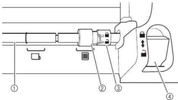
①Shaft
②Feed roller
☐: Move the feed roller to this position for normal operations.
☐: Move the feed roller to this position when the roll feeder is being used.
③Feed roller lock dial
Rotates forward/backward to lock/release the feed roller.
④Feeder release lever
Locks/releases the shaft.
1 Pull the feeder release lever toward you to release the shaft.
2 Rotate the feed roller lock dial toward the back to unlock the feed roller, and then move the feed roller to the mark.
3 Rotate the feed roller lock dial toward you to lock the feed roller, and then push the feeder release lever to the position.

Note
- Be careful not to pinch your fingers while operating the feeder release lever.
TROUBLESHOOTING
Please pay attention to all applicable safety warnings when referring to the sections cited below.
If the machine stops operating correctly, check the following possible problems before requesting service.
You can solve most problems by yourself. If you need additional help, the Brother support website offers the latest FAQs and troubleshooting tips. Visit us at "http://s.brother/cpoac/".
If the problem persists, contact the retailer who sold you this machine or the nearest authorized service center.
For wireless network troubleshooting, refer to "WIRELESS NETWORK CONNECTION FUNCTION" on page 86.
Power Supply
| Symptom Possible Causes (or Results) Solutions Reference | |||
| The machine cannot be turned on. | The AC power cord is not correctly connected to the machine. | Check that the power cord is connected to the electrical outlet. | page 8 |
Mat
| Symptom Possible Causes (or Results) Solutions Reference | |||
| The mat cannot be inserted. | When the mat was inserted, it was not placed under the feed rollers. | Insert the mat so that it is placed under the feed rollers on the left and right sides of the feed slot. | page 29 |
| The mat was not loaded using the “Feed” button. | Lightly insert the mat into the feed slot, and then press the “Feed” button. | page 29 | |
| The feed roller is not positioned correctly. | Adjust the position of the feed roller. page 109 | ||
| The shaft is released. | Lock the shaft. | page 109 | |
| The mat cannot be recognized. | The dotted marks on the part of the mat that is inserted are dirty. | Clean the dotted marks on the mat and their surrounding area. | page 104 |
| The dotted marks on the part of the mat that is inserted are hidden by material or tape that was attached. | Attach the material or tape while keeping it within the adhesive area of the mat. | page 19 | |
| The mat was inserted so that the side with the material attached is facing down. | Insert the mat so that the side with the material attached is facing up. | page 29 | |
| The mat was inserted in the wrong direction. | Insert the mat in the correct direction. page 29 | ||
| The scanner glass is dirty. | Clean the scanner glass inside the machine. | page 106 | |
| A mat designed specifically for this machine is not used. | Replace the mat with one designed specifically for this machine. | - | |
| The mat is fed in at an angle. | The mat was inserted into the feed slot at an angle. | Press the “Feed” button to feed out the mat, and then re-insert it straight in. | page 29 page 30 |
| The corners of the mat are deformed (bent). | Replace the mat with a new one. page 102 | ||
| The rear tray is not pulled out. Pull out the rear tray. | page 7 page 9 | ||
| The feed roller is not positioned correctly. | Adjust the position of the feed roller. page 109 | ||
| The material to be cut/ drawn or original to be scanned cannot be attached to the mat. | The material extends from the adhesive area of the mat. | Attach the material while keeping it within the adhesive area of the mat. | page 19 |
| The mat’s adhesive strength has decreased. | Replace the mat with a new one. page 102 | ||
| The mat cannot be fed out. | The material to be cut/drawn or original to be scanned is jammed in the feeding mechanism in the machine. | Press the “Feed” button while the mat is being inserted to feed it out. If the mat does not feed out, turn off the machine, and then carefully pull out the mat. | page 30 |
| Symptom Possible Causes (or Results) Solutions Reference | |||
| When the mat is inserted, the attached material peels off. | The mat is not level due to the weight of the material. | With your hands, hold the mat level when inserting it. | page 29 |
| The mat's adhesive strength has decreased. | Replace the mat with a new one. page 102 | ||
Paper/Fabric Jam
| Symptom Possible Causes (or Results) Solutions Reference | |||
| The mat cannot be fed. | There is an obstruction around the slot at the back of the machine. | Maintain space around the slot at the back of the machine so that the mat can be fed out. | page 8 |
| The surface where the machine is installed is uneven. | Place the machine on a flat, even surface. | — | |
| The mat or the material catches on a feed roller when the mat is being inserted. | The mat's adhesive strength has decreased, or the material is not secured. | Press the “Feed” button to feed out the mat, and then replace the mat with a new one. | page 30 page 102 |
| The material or tape is extending from the adhesive surface. | After pressing the feed button and removing the mat, attach the material or tape so that it fits on the adhesive surface of the mat. | page 19 page 30 | |
| The thickness of the material exceeds the maximum limit. | Press the “Feed” button to feed out the mat, raise the scanner lever, and then correctly insert the mat. | page 7 page 9 page 30 | |
| Press the “Feed” button to feed out the mat, and then change the material to a thin one. | — | ||
| The mat or the material catches on a feed roller during cutting/drawing/scanning. | - The mat's adhesive strength has decreased, or the material is not secured.- The material extends from the adhesive area of the mat.- The rear tray is not pulled out. | Press the “Pause/Stop” button to stop the operation. Follow the instructions on the screen, and press the “Feed” button to feed out the mat.If the mat does not feed out, turn off the machine, remove the holder, and then manually feed out the mat.After feeding out the mat, replace it with a new one or attach the material while keeping it within the adhesive area of the mat. Pull out the rear tray, and then insert the mat. | page 7 page 9 page 19 page 30 page 102 |
| The mat is fed in at an angle and is not fed during cutting/drawing/scanning. | |||
| The material to be cut/drawn or original to be scanned peels off during cutting/drawing/scanning. | |||
Cutting
| Symptom Possible Causes (or Results) Solutions Reference | |||
| The material being cut catches on the tip of the cutting blade. | Dust or lint has accumulated in the holder. | Clean the holder. page 104 | |
| The blade is worn. | Replace the blade with a new one. | page 102 | |
| The material being cut is incompatible with this machine. | Replace the material with one compatible with this machine. | page 16 | |
| The machine stopped while an operation is being performed. | For safety, the machine stops operating if the panel is touched while cutting. | Follow the instructions in the message that appears in the screen. Touch the “OK” key to move the carriage to its initial position. Load the mat and perform the operation again. | — |
| Symptom | Possible Causes (or Results) | Solutions | Reference |
| Not all of the material to be cut is cut. Some areas remain uncut. | A blade appropriate for the material being cut is not used. | Use a blade appropriate for the material being cut. | page 16 |
| If the Cut Pressure setting value is increased and you are still having issues cutting evenly, the blade may be chipped. | Replace the blade with a new one. page 102 | ||
| The mat's adhesive strength has decreased, or the material is not secured. | Replace the mat with a new one. page 102 | ||
| The blade is worn. | Replace the blade with a new one. | page 102 | |
| The material is incompatible with this machine. | Replace the material with one compatible with this machine. | page 16 | |
| The cutting pressure ("Cut Pressure") is incorrect. | Adjust the setting for "Cut Pressure" in the settings screen. | page 10 page 30 | |
| Dust or lint has accumulated in the holder. | Clean the holder. page 104 | ||
| The spacing between arranged patterns is too small. | Rearrange the patterns to slightly separate them. Set the number to "3" or higher in the "Pattern Interval" setting, and then rearrange the patterns or perform the auto layout function. | page 10 page 54 | |
| The material or tape extends from the adhesive area of the mat. | Attach the material or tape while keeping it within the adhesive area of the mat. | page 19 | |
| Fabric was cut without using a sheet for fabric cutting. | Attach a high tack adhesive fabric support sheet to a mat or affix an iron-on fabric appliqué contact sheet to a fabric before cutting it. | page 20 page 24 | |
| A fabric is not firmly attached to a mat that has a high tack adhesive fabric support sheet on its adhesive side. | Firmly attach the fabric to the mat pressing the handle of the included spatula across the surface of the fabric. | page 24 | |
| An iron-on fabric appliqué contact sheet is not firmly attached to a fabric. | Iron the entire contact sheet to affix it firmly to the wrong side of the fabric. | page 20 | |
| There are deep cuts completely through the mat. | The cutting pressure ("Cut Pressure") is incorrect. | Adjust the setting for "Cut Pressure" in the settings screen. | page 10 page 30 |
Drawing
| Symptom Possible Causes (or Results) Solutions Reference | |||
| The drawn line is thicker (thinner) than intended. | The drawing speed (“Draw Speed”) or drawing pressure (“Draw Pressure”) is incorrect. | Adjust the settings for “Draw Speed” and “Draw Pressure” in the settings screen.To draw thicker lines, increase the drawing pressure. To draw thinner lines, decrease the drawing pressure.To draw thicker lines, reduce the drawing speed. To draw thinner lines, increase the drawing speed.After adjusting the settings, perform a test/trial drawing operation. | page 10page 58 |
| The machine stopped while an operation is being performed. | For safety, the machine stops operating if the panel is touched while drawing. | Follow the instructions in the message that appears in the screen. Touch the “OK” key to move the carriage to its initial position. Load the mat and perform the operation again. | — |
Scanning
| Symptom Possible Causes (or Results) Solutions Reference | |||
| Unwanted images are scanned. | The scanning area is incorrectly specified. | In “Scan to USB” mode, specify the paper size with the “Scan Size” setting. | page 82 |
| In “Direct Cut” or “Scan to Cut Data” mode, trim the image in the editing screen after scanning. | page 68 page 74 | ||
| Scanning cannot be done cleanly (there are lines in the scanned image). | The scanner glass is dirty. | Clean the scanner glass inside the machine. | page 106 |
| The original to be scanned is dirty or scratched. | In “Direct Cut” or “Scan to Cut Data” mode, remove thin lines or dirt in the image editing screen. | page 80 | |
| The lines printed on the mat are scanned. | The original is transparent so the lines printed on the mat are being scanned. | In “Direct Cut” or “Scan to Cut Data” mode, remove the lines in the image editing screen. | page 80 |
| The scanned image is red. | When the optional scanning mat is used, scanning is performed without peeling off the blue tape. | Peel off the blue tape from the optional scanning mat before scanning. | — |
| The scan image is out of focus. | The scanner lever is not correctly positioned for the thickness of the material | Set the scanner lever position to “1”. page 9 | 9 |
Data Transfer
| Symptom Possible | Causes (or Results) Solutions Reference | |
| The data retrieved with the machine is different from the transferred data. | Multiple data items are being transferred from CanvasWorkspace, Artspira App or from a machine using the “My Connection” function. | Only a single file of data can be transferred over the server. If data is repeatedly transferred before retrieving it with the cutting machine, it is updated to the latest data. |
| Transferred data cannot be retrieved. | The storage period on the server has elapsed. | Data is erased from the server after a certain period of time has elapsed since the data was transferred. Retrieve the data on the machine as soon as possible after transferring the data. |
| The cutting machine was not registered on CanvasWorkspace at the time the data was transferred from the embroidery machine using the “My Connection” function. | Register the cutting machine with CanvasWorkspace machine registration, and transfer the data from the embroidery machine again. |
How can I Find the Wireless Security Information (Network Name (SSID) and Network Password)
Please do not contact Brother Customer Service for assistance without the wireless security information. We cannot assist you in locating your network security settings.
1) You should see the documentation provided with your wireless access point/router.
2) The default Network Name (SSID) could be the manufacturer's name or the model name.
3) If you do not know the security information, please consult the router manufacturer, your system administrator, or internet provider.
4) Some Wireless Network Name (SSID) and Network Password (Key) are case (upper case and lower case) sensitive. Please properly record your information.
* The Network Password may also be described as the Network Key, Security Key or Encryption Key.
* If the wireless access point/router is not broadcasting the Network Name (SSID), the Network Name (SSID) will not automatically be detected. You will have to manually enter the Network Name (SSID).
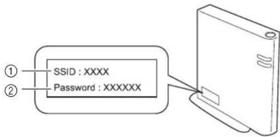
The following table lists some of the messages that may appear while the machine is operating as well as their corresponding solutions.
Perform the necessary operation according to the instructions in the message or the solution described here. If the problem persists, contact the retailer who sold you this machine or the nearest authorized service center.
| Error Messages Causes / Solutions | |
| A malfunction occurred.Turn the machine off, then on again. | Turn the machine off, then on again. |
| Cannot operate when there are too many patterns. | The message appears under the following conditions:- In “Direct Cut” mode, more than the maximum number of patterns have been detected for the cutting pattern.- In “Scan to Cut Data” mode, more than the maximum number of patterns are being saved as cutting data.Reduce the number of patterns being used.* Depending on the machine model, the maximum number of patterns will differ. Check the “Maximum Pattern Number” under “Machine Information” of the settings screen.- There are too many cutting lines to be created after large number of small patterns are scanned.- There are too many light tone patterns to be converted to two-tone (black and white) patterns while the image detection level is being adjusted.Scan images again after reducing the number of patterns arranged in the original. |
| Cannot operate when there is no pattern. | There is no scanned image or lines for scanning.Recheck the image to be scanned, and adjust the scanning area, image detection level and “Ignore Object Size” settings.In addition, change the image drawn on the original to one more easily scanned. |
| Cannot read the data.Get the PIN code again and register to the machine. | - This message appears when you try to transfer data with a machine different than the one registered with CanvasWorkspace.- The registration of your machine has been canceled from CanvasWorkspace. Register the machine to be used again. |
| Cannot save the data.Get the PIN code again and register to the machine. | |
| Includes a special pattern that cannot be saved to external memory.Save the pattern in the machine’s memory. | Depending on the pattern, it may not be possible to save it to external memory (USB flash drive or CanvasWorkspace). |
| Initialization of the blade position failed.Turn the machine off. | Turn the machine off, then on again. |
| Initialization of the head failed.Turn the machine off. | |
| No more patterns can be added to this combination. | More than the maximum number of patterns are being combined. Reduce the number of patterns.* Depending on the machine model, the maximum number of patterns will differ. Check the “Maximum Pattern Number” under “Machine Information” of the settings screen. |
| No pattern in the effective area. | There is no pattern(s) to be cut out or drawn within the cutting area.To cut out or draw a pattern outside of the area, increase the setting for “Cut Area”, or move the pattern(s) into the area specified with “Cut Area” (page 10). |
| Not enough available memory to save the data. | Delete a file from the machine’s memory or USB flash drive. |
| Not enough space on the mat.Check pattern size, space on the mat, Cut Area (setting) or Pattern Interval (setting). | Perform one of the following to arrange the patterns.- Delete a pattern already arranged in the mat layout screen.- Resize a pattern in the arrangement.- Enlarge the setting for “Cut Area” (page 10).- Reduce the spacing between arranged patterns using the “Pattern Interval” setting. |
| Not enough space on the mat.Max: 10 (example: calculated number) | Since there are too many patterns, they cannot be arranged.Reduce the number of patterns to the maximum shown on the screen. |
| OK to retrieve and resume previous memory? | To use data from the previous operation, touch the “OK” key. (page 12) |
| Pattern cannot be grouped.Invalid pair was selected. | The message appears when you are unifying patterns. Patterns with seam allowances and no seam allowances are selected as pairs. Select patterns, all of which have either seam allowances or no seam allowances. |
| Patterns cannot be welded.There are some patterns which cannot accept or no overlaps. | The message appears when you are welding patterns.- The patterns do not overlap. Rearrange them so the selected patterns overlap. Unifying the pattern, instead, can be an alternative editing method depending on your project.- A pattern that has a seam allowance is selected.Deactivate the seam allowance setting and weld the patterns.- An open shape is selected as a pattern. Only closed shapes can be welded. Unifying the pattern, instead, can be an alternative editing method depending on your project. |
| Replace the mat with 12 × 24 inch mat. | The 12" × 12" mat was loaded although 24-inch data was created. Load the 12" × 24" mat. |
| Scanning error occurred.Turn the machine off. | Turn the machine off, then on again, and then try performing the operation again. |
| Since the shape was larger than the mat, it was reduced in size when imported. | If the pattern in the imported SVG file is larger than the mat, the pattern will be reduced to fit the size of the mat. If necessary, in the software used to create the SVG file, edit the pattern to fit the size of the mat. |
| Some shapes could not be converted. | The imported SVG data contains data that cannot be converted, such as images or text. All other data was read as cutting line data. |
| The data cannot be deleted. | The USB flash drive being used may not be usable with this machine. If removing the USB flash drive and performing the operation again causes the message to appear again, replace the USB flash drive. For information about USB flash drive compatible with this machine, visit our website “http://s.brother/cpoac/”. |
| The data cannot be read. | |
| The data cannot be saved. | |
| The data could not be imported.There are too many patterns. | The message appears when an SVG file contains more than the maximum number of patterns. In the software used to create the SVG file, reduce the number of patterns.* Depending on the machine model, the maximum number of patterns will differ. Check the “Maximum Pattern Number” under “Machine Information” of the settings screen. |
| The data is too complicated to be imported. | SVG files containing a complicated pattern cannot be imported. In the software used to create the SVG file, simplify the pattern. |
| The mat cannot be recognized.The mat will unload. | A mat that cannot be recognized has been inserted. If a mat designed specifically for this machine is not being used, use the specially designed mat. |
| Clean the dotted marks at the edge of the mat and their surrounding area. If the mat is still not recognized, replace the mat with a new one. | |
| There are no patterns that can be detected. | The imported SVG data contains data that cannot be converted, such as images or text. |
| There are some patterns which cannot add seam allowance. | The seam allowance settings cannot be specified for complex pattern shapes. Select a pattern with a simple shape.Expanding the seam allowance to 2 mm or more may help. |
| There are some patterns which cannot set cutting distance from the outline. | The cutting distance cannot be specified for complex pattern shapes. Select a pattern with a simple shape. |
| This data is too complicated and cannot be converted. | Complex patterns cannot be welded or filled.Reduce the number of patterns arranged or change the patterns to ones with simple designs. |
| This mat cannot be used. | The mat is one that cannot be used with the function being performed. Replace the mat.(For example, the scanning mat was loaded while trying to cut.) |
| Cooling Down | The machine has stopped cutting/drawing to cool down the hot part inside the machine.Leave it for a while then follow the instruction on the screen to restart.If this message appears often, contact the retailer who sold you this machine or the nearest authorized service center. |
When Setting Up the Wireless Network
The following table contains a list of the various messages that may appear during setup or while registering the machine with CanvasWorkspace as well as the appropriate solutions.
Perform the necessary operation according to the instructions in the message or the solution described here. If the problem persists, contact the retailer who sold you this machine or the nearest authorized service center.
| Error code Cause/Solution | ||
| Err-01 | The wireless network setting is not activated.Activate the wireless network.See “Enable the Wireless Network Function” on page 86. | |
| Err-02 | The wireless access point/router cannot be detected.1. Check the following 4 points.- Make sure that the wireless access point/ router is powered on.- Move your machine to an area with no items which obstruct the wireless network signal, such as metal doors or walls, or closer to the wireless access point/router.- Temporarily place your machine within about 1 m (3.3 feet) from the wireless access point when you are configuring the wireless settings.- If your wireless access point/router is using MAC address filtering, confirm the MAC address of this machine is allowed in the filter.2. If you manually entered the Network Name (SSID) and security information (Network Name (SSID)/authentication method/encryption method/Network Password (Network Key)), the information may be incorrect. Reconfirm the Network Name (SSID) and security information and re-enter the correct information as necessary.See “How can I Find the Wireless Security Information (Network Name (SSID) and Network Password)” on page 114 to confirm. | |
| Error code Cause/Solution | ||
| Err-03 | The Authentication/Encryption methods used by the selected wireless access point/router are not supported by your machine.For infrastructure mode, change the authentication and encryption methods of the wireless access point/router.Your machine supports the following authentication methods: | |
| Authentication method Encryption method | ||
| WPA-Personal TKIP | ||
| AES | ||
| WPA2-Personal TKIP | ||
| AES | ||
| Open WEP | ||
| None (without encryption) | ||
| Shared key WEP | ||
| If your problem is not solved, the Network Name (SSID) or network settings you entered may be incorrect. Reconfirm the wireless network settings.See “How can I Find the Wireless Security Information (Network Name (SSID) and Network Password)” on page 114 to confirm. | ||
| Err-04 | The security information (Network Name (SSID)/Network Password (Network Key)) is incorrect.Reconfirm the Network Name (SSID) and security information (Network Password (Network Key)).See “How can I Find the Wireless Security Information (Network Name (SSID) and Network Password)” on page 114 to confirm. | |
| Err-05 | The wireless security information (Authentication method/Encryption method/Network Password (Network Key)) is incorrect.Reconfirm the wireless security information (Authentication method/Encryption method/Network Password (Network Key)) in the table of Err-03.See “How can I Find the Wireless Security Information (Network Name (SSID) and Network Password)” on page 114 to confirm. | |
| Err-20 | The machine is still trying to connect to your wireless network. Please wait a few minutes, and then check the WLAN status. | |
When Registering the Machine with CanvasWorkspace
| Error message Cause/Solution | |
| A network error occurred. | A network error occurred during communication.Check the following.- Is your wireless access point/router turned on?- Is the network cable of your wireless access point/router plugged in? |
| Errors occurred in network function. | An internal malfunction occurred.Contact the retailer where you purchased this machine or the nearest authorized service center. |
| Registration failed. | Registration of the PIN code failed.Internal data may be corrupted.Contact the retailer where you purchased this machine or the nearest authorized service center. |
| Unconnected to the internet server.Check the proxy setting. | The proxy settings are incorrect.Check the proxy settings of your wireless network and your machine. |
| Unconnected to the network.Check the network connection status. | The machine is not connected to the network.- Check that there is a good network connection.- A network connection may not yet be established.Wait a while, and then try again. |
UPDATING THE SOFTWARE
The machine's software can be updated with any of the following three procedures.
- Updating Using Automatic Update Function
- Updating from the Home Screen
- Updating from the Settings Screen
- Updating Using a USB Flash Drive
- Updating Using the Application
(CanvasWorkspace)

Memo
- The guides and information listed under "Manuals" on Brother support website (https://s.brother/cmoae/) may update as well. Please check this website after updated the machine's software.
Automatic Update Function
The machine can be updated by retrieving update files directly from the Internet.

Memo
- Before using this function, register your machine with CanvasWorkspace, and connect the machine to the network. For details on registering, refer to "WIRELESS NETWORK CONNECTION FUNCTION" on page 86.
■Updating from the Home Screen

Touch in the home screen.
- If there is no new update file, in the home screen.

not appear
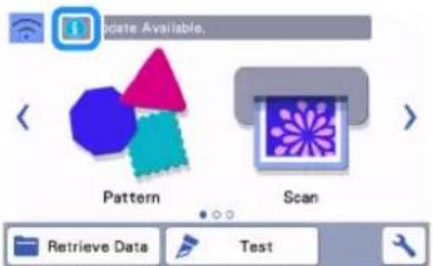

Touch the "Update" key to retrieve the software.

When the update is finished, the machine automatically restarts.

Note
- Do not turn off the machine while it is being updated.
■Updating from the Settings Screen

Touch in the home screen to display the settings screen, and then touch the "Ver." button.

The update method selection screen appears.

Touch


①Update automatically

Updating begins.
- Refer to step 2 in "Updating from the Home Screen".
If there is no new update file, the following message appears.


Note
- If the automatic update fails, retrieve the update file from the Brother support website (http://s.brother/cuoad/), and then update your machine using a USB flash drive.
Update Procedure Using USB Flash Drive
Using a USB flash drive, the machine's software can be updated. For update information, refer to details posted on the Brother support website (http://s.brother/cuoad/). If an update file is posted, download the file, and then update the machine according to the following procedure.
1 Insert the USB flash drive containing the update file into the USB port on this machine.
The USB flash drive must not contain any data other than the update file. Otherwise, the machine may stop operating correctly.


Note
- This machine is incompatible with a USB hub. Insert the USB flash drive directly into the USB port.
2 Touch in the home screen to display the settings screen, and then touch the "Ver." button.

The update method selection screen appears.

Touch


①Update using USB flash drive
4 Touch the "Update" key to start the update.

When the update is finished, the machine automatically restarts.
5 Remove the USB flash drive from the port.

Note
- Do not remove the USB flash drive while the machine is being updated.
Update Procedure Using the Application (CanvasWorkspace)
With this function, the machine can be connected to a computer with a USB cable in order to retrieve the update file from CanvasWorkspace to update the machine. Before using this function, install CanvasWorkspace on the computer.
■USB cable (sold separately)
- We recommend using a USB 2.0 cable (Type A/B) that is no longer than 2 meters (6 feet).
1 Insert the USB cable connectors into the corresponding USB ports on the computer and on the machine, and then turn on the machine.
2 Display the home screen on the machine.
3 Start up CanvasWorkspace, and then click [Check for the Latest ScanNCut DX Update...] on the [Help] menu.
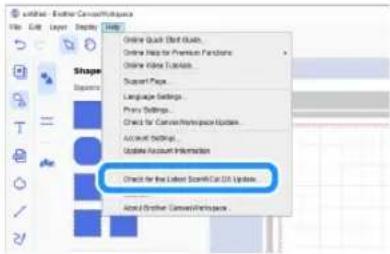
When the following message appears, click [OK] to update the software.

If there is no new update file, the following message appears.

4 When the machine receives the update file, the following screen appears. When the update is finished, the machine automatically restarts.
OPTIONAL ACCESSORIES
The following are available as optional accessories to be purchased separately.
1.2.3.

4.5.6.


7.8.9.

-
- 12.


-
- 15.

-
- 18.

-
- 21.

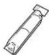

-
- 24.
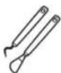


-
- 27.

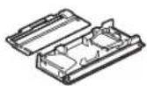
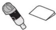
-
- 30.


| No. | Part Name Part Code | |
| 1 | Low Tack Adhesive Mat 12" × 12" (305 mm × 305 mm) | CADXMATLOW12 |
| 2 | Standard Tack Adhesive Mat 12" × 12" (305 mm × 305 mm) | CADXMATSTD12 |
| No. | Part Name Part Code | |
| 3 | Low Tack Adhesive Mat 12" × 24" (305 mm × 610 mm) | CADXMATLOW24 |
| 4 | Standard Tack Adhesive Mat 12" × 24" (305 mm × 610 mm) | CADXMATSTD24 |
| 5 | Fabric Mat 12" x12" (305 mm × 305 mm) | CADXMATF12 |
| 6 | Standard Cut Blade Holder (turquoise) (with no blade) | CAHLP1 |
| 7 | Standard Cut Blade CABLDP1 | |
| 8 | Scanning Mat 12" × 12" (305 mm × 305 mm) | CADXMATS12 |
| 9 | Scanning Mat 12" × 24" (305 mm × 610 mm) | CADXMATS24 |
| 10 | Deep Cut Blade Holder (purple) (with no blade) | CAHLF1 |
| 11 | Deep Cut Blade CABLDF1 | |
| 12 | Auto Blade Holder CADXHLD1 | |
| 13 | Auto Blade CADXBLD1 | |
| 14 | Thin Fabric Auto Blade Holder CADXHLDQ1 | |
| 15 | Thin Fabric Auto Blade CADXBLDQ1 | |
| 16 | Pen Holder CAPENHL1 | |
| 17 | Universal Pen Holder | CAUNIPHL1 |
| 18 | Color Pen Set | CAPEN1 |
| 19 | Erasable Pen Set | CAPEN2 |
| 20 | Iron-on Fabric Appliqué Contact Sheet (White Backing) | CASTBL1 |
| 21 | High Tack Adhesive Fabric Support Sheet | CASTBL2 |
| 22 | Spatula and Hook Set | CASPHK1 |
| 23 | Precision Tweezers | CATWZ1 |
| 24 | 3.9 inch (100 mm) Scraper | CASCP1 |
| 25 | 4 inch (102 mm) Brayer / Roller | CABRY1 |
| 26 | Roll Feeder 2 | CADXRF2 |
| 27 | Vinyl Auto Blade Kit | CADXVBKIT1 |
| 28 | Vinyl Auto Blade | CADXBLDV1 |
| 29 | Rotary Auto Blade Kit | CADXRBKIT1 |
| 30 | Rotary Auto Blade CADXBLDR1 |
* Contact the retailer who sold you this machine or the nearest authorized service center.
* Use a mat designed specifically for this machine. The machine will not operate correctly if any other mat is used.
* For the newest information and manuals on optional accessories compatible with this machine, refer to the Brother support website (http://s.brother/ccob/).
* The blade extension and cutting pressure must be adjusted manually with the Standard Cut Blade Holder (turquoise) and Deep Cut Blade Holder (purple). For details on making adjustments, refer to the Brother support website (http://s.brother/cfoae/).
PRODUCT SPECIFICATIONS
| Items Specifications | |
| Dimensions | Approx. 531 mm (W) × 215 mm (D) × 173 mm (H)(Approx. 20.9 inches (W) × 8.5 inches (D) × 6.8 inches (H)) |
| Weight Approx. 6 kg (Approx. 13.2 lb) | |
INDEX
A
AC power jack 7
Advanced pattern cutting 35
Aligning Patterns 52
Artspira 5,96
Auto shutdown 11, 12
B
Background 10
Background scanning ....54
Basic pattern cutting 32
Buzzer sound ....11
C
CanvasWorkspace ....5, 65, 90, 93
Carriage 6,27
Character input functions ....56
Cleaning 104
Cut area 10,45
Cut pressure 10
Cut speed 10
Cutting around drawings 59
Cutting blade replacement 102
Cutting line 76
D
Direct cut 68
Color recognition mode 69
Grayscale recognition mode 69
Draw pressure 11,59
Draw speed 11,59
Drawing functions ....58
E
Error messages ....115
F
Feed slot 29
G
Grouping/Ungrouping Patterns 48
H
High tack adhesive fabric support sheet .....14, 24
Holder lock lever 6,27
Holder setting 27
Home screen 9,32
|
Image editing screen 71, 76, 77, 80
Image trim screen 70, 72, 77
Iron-on fabric appliqué contact sheet 14, 20
L
Language 10
Layout editing functions 46
Layout Interval 10
Low tack adhesive mat ....14
M
Main power switch 8, 32
Mat and material combinations ....16
Mat editing screen 42
Mat layout screen 33,45
Mat loading 29
Mat unloading ....30
My Connection 97
O
Opening screen 8,11
Operation panel 7
Optional accessories ....123
Outline distance 72
Outlining and framing 73
P
Parts and functions ......6
Pattern category selection screen ....32
Pattern editing functions ......44
Pattern editing screen 32, 44
"Pattern" mode 4
Pattern piece editing screen ....36, 45
Pattern piece list screen ....36
Pattern selection screen 32, 36
Pattern sizing screen 36
Pattern sub-category selection screen ....35
PES 98
PHC 98
PHX 98
Picture editing 80
Preview screen 34
R
Rear tray 7,9
Attaching 106
Removing 106
Recalling 66
Replacement criteria 102
Required material condition (scanning) ......68, 82
S
Saving 65
"Scan" mode 4,68
Scan to cut data 74
Color recognition mode 75
Grayscale recognition mode 74
Scan to USB 82
Scanner lever 6, 9, 59, 70
Scanning/Cutting position calibration 107
Seam allowance 11, 47, 59
Selecting multiple patterns 42
Settings screen 10
Software update ....120
Standard tack adhesive mat ....14
T
Terms of Use ....i
Test/Trial Cut 28
Touch screen calibration 107
Troubleshooting....110
U
Unit 10
USB port 7,65,121
W
Welding (merging the outlines of multiple patterns) ....50
Wireless network 5, 12, 65
Wireless network connection function 86
Please visit us at http://s.brother/cpoac/ where you can get product support and answers to frequently asked questions (FAQs).
These machines are approved for use in the country of purchase only. Local Brother companies or their dealers will only support machines purchased in their own countries.


- TERMS OF USE
- IMPORTANT-PLEASE READ CAREFULLY
- TERMS AND CONDITIONS
- 1 GRANT OF LICENSE
- 2 RESTRICTIONS
- 4 LIMITATION OF LIABILITY
- 5 T E R M I N A T I O N
- 6 MISCELLANEOUS TERMS
- INTRODUCTION
- IMPORTANT NOTICE
- IMPORTANT SAFETY INSTRUCTIONS
- SYMBOLS USED IN THIS DOCUMENT
- CONTENTS
- 1 GETTING STARTED......6
- 2 BASIC OPERATIONS......14
- 3 ADVANCED OPERATIONS...44
- 4 SCANNING FUNCTIONS ... 68
- 5 WIRELESS NETWORK CONNECTION FUNCTION... 86
- 6 DATA TRANSFER FUNCTION... 93
- RETRIEVING EMBROIDERY DATA FOR CUTTING
- 7 APPENDIX......102
- PATTERNS ("PATTERN" MODE)
- SCANNING ("SCAN" MODE)
- TRANSFERRING DATA USING THE WIRELESS NETWORK CONNECTION FUNCTION
- CONNECTING TO A WIRELESS NETWORK
- REGISTER MACHINE UNDER CANVASWORKSPACE
- RETRIEVING/SAVING PATTERNS
- CHAPTER 1 GETTING STARTED
- PARTS AND FUNCTIONS
- UNIT DESCRIPTIONS - FRONT
- ①OPERATION PANEL
- ②TOOL TRAY
- ③CARRIAGE
- ①HOLDER
- ②HOLDER GUIDE
- ③HOLDER LOCK LEVER
- ④SCANNER LEVER
- ⑤GRIPS
- ⑥FEED ROLLERS
- ⑦SHAFT
- ⑧FEEDER RELEASE LEVER
- ⑨TOOL HOLDER
- ⑩STORAGE
- ⑪FRONT TRAY COVER
- ⑫FEED SLOT
- UNIT DESCRIPTIONS - REAR
- UNIT DESCRIPTIONS - OPERATION PANEL
- INCLUDED ACCESSORIES
- PLACING THE MACHINE
- REMOVING THE PACKING MATERIALS
- NOTE
- TURNING ON/OFF THE MACHINE
- MEMO
- PREPARING FOR FEEDING THE MAT
- OPERATION OF LCD PANEL
- SETTINGS SCREEN
- GROUP 1
- LANGUAGE
- UNIT
- CUT AREA
- PATTERN INTERVAL
- BACKGROUND
- GROUP 2
- CUT SPEED
- CUT PRESSURE
- CUT PRESSURE (MANUAL BLADE)
- CUT AMOUNT
- HALF CUT
- CUT PRESSURE (HALF CUT)
- CUT MODE (ROTARY BLADE)
- BLADE ADJUSTMENT AREA
- BLADE ADJUSTMENT AREA (ROTARY BLADE)
- DRAW SPEED
- DRAW PRESSURE
- GROUP 3
- SEAM ALLOWANCE
- FILL
- ADDITIONAL LINE
- GROUP 4
- AUTO SHUTDOWN
- BUZZER SOUND
- OPENING SCREEN
- SCANNING/CUTTING POSITION ADJUSTMENT
- GROUP 5
- NO
- VER
- MACHINE INFORMATION
- GROUP 6
- NETWORK
- GROUP 7
- MACHINE REGISTRATION
- GROUP 8
- PREMIUM FUNCTIONS
- GROUP 9
- RESET
- FIRST STEPS
- SELECTING THE MAT AND BLADE APPROPRIATE FOR THE MATERIAL
- REFERENCE TABLE OF MAT, BLADE AND MATERIAL COMBINATIONS
- ATTACHING THE MATERIAL TO THE MAT
- MATERIAL
- PAPER
- ATTACHING THE MATERIAL (PAPER)
- TEST ATTACHING THE MATERIAL
- ATTACH THE MATERIAL TO THE MAT'S ADHESIVE SIDE
- ☐ PEELING OFF THE MATERIAL (PAPER)
- FABRIC (OTHER THAN FOR QUILT PIECING)
- ATTACHING FABRIC MATERIAL TO A MAT USING IRON-ON FABRIC APPLIQUÉ CONTACT SHEET
- 1 PEEL OFF THE PROTECTIVE SHEET FROM THE ADHESIVE SIDE OF THE STANDARD TACK ADHESIVE MAT
- ☐ PEELING OFF THE MATERIAL
- ATTACHING FABRICS WITH THE DOUBLE-SIDED ADHESIVE
- NOTICE ON USE OF IRON-ON FABRIC APPLIQUÉ CONTACT SHEET
- ☐ CUTTING FABRIC OTHER THAN QUILT PIECES USING THE ROTARY AUTO BLADE HOLDER
- 1 PEEL OFF THE PROTECTIVE SHEET FROM THE ADHESIVE SIDE OF THE MAT
- 2 TEST ATTACHING THE MATERIAL
- 3 FROM ITS EDGES, ATTACH THE MATERIAL TO THE ADHESIVE SIDE OF THE MAT SO THAT THERE ARE NO WRINKLES IN THE MATERIAL
- 4 FIRMLY MOVE THE SPATULA HANDLE ACROSS THE SURFACE OF THE FABRIC TO REMOVE ANY WRINKLES AND FIRMLY ATTACH THE FABRIC TO THE MAT
- FABRIC (FOR QUILT PIECING)
- ATTACHING THE MATERIAL USING A HIGH TACK ADHESIVE FABRIC SUPPORT SHEET
- ☐ PEELING OFF THE MATERIAL (FABRIC FOR QUILT PIECING)
- ☐ NOTICE ON USE OF HIGH TACK ADHESIVE FABRIC SUPPORT SHEET
- ATTACHING THE MATERIAL TO THE FABRIC MAT
- ☐ CUTTING FABRIC FOR QUILT PIECING WITH THE ROTARY AUTO BLADE HOLDER
- INSTALLING AND UNINSTALLING THE HOLDER
- 1 PRESS IN THE OPERATION PANEL TO TURN ON THE MACHINE
- 2 REMOVE THE PROTECTIVE CAP
- WARNING
- CAUTION
- 3 GRASP THE HOLDER GRIP, AND THEN INSERT THE HOLDER INTO THE CARRIAGE
- 4 PUSH DOWN ON THE HOLDER LOCK LEVER
- 5 REVERSE THE INSTALLATION PROCEDURE TO UNINSTALL THE HOLDER
- TEST CUT (TRIAL CUT)
- TURNING ON THE MACHINE
- SETTING THE HOLDER
- SELECTING THE TEST PATTERN
- LOADING THE MAT
- 1 ATTACH THE MATERIAL THAT WILL BE CUT TO THE MAT
- 2 WHILE HOLDING THE MAT LEVEL, GENTLY INSERT IT INTO
- CUTTING
- 1 SELECT "CUT" IN THE TEST SCREEN
- 2 TOUCH THE "START" KEY TO START CUTTING
- UNLOADING THE MAT
- CHECKING THE TEST/TRIAL CUT RESULTS
- ☐ WITH AN APPROPRIATE CUTTING PRESSURE
- CHANGING THE AUTO CUTTING PRESSURE
- CHANGING THE CUT PRESSURE SETTING
- HALF CUT (KISS CUT) SETTINGS
- PATTERN CUTTING
- TUTORIAL 1 - CUTTING PATTERNS
- SELECTING AND EDITING THE FIRST PATTERN
- SELECTING AND EDITING THE SECOND PATTERN
- 1 TOUCH THE "ADD" KEY IN THE MAT LAYOUT SCREEN
- 2 SELECT THE LOCATION OF THE PATTERN TO BE ADDED
- 3 SELECT THE CATEGORY FOR THE PATTERN TO BE CUT OUT
- 4 SELECT THE SECOND PATTERN TO BE USED
- 5 EDIT THE PATTERN
- 6 CHECK THE PATTERN ARRANGEMENT
- TUTORIAL 2 - CUTTING ADVANCED PATTERNS
- SELECTING AND EDITING THE FIRST PATTERN PIECE
- 4 SELECT THE PATTERN TO BE CUT OUT IN THE PATTERN SELECTION SCREEN
- 5 EDIT THE SIZE OF THE ENTIRE PATTERN USING THE PATTERN SIZING SCREEN
- 6 SELECT THE PIECE TO BE EDITED FIRST IN THE PATTERN PIECE LIST SCREEN, AND THEN TOUCH THE "OK" KEY
- 7 EDIT THE PATTERN PIECE USING THE PATTERN PIECE EDITING SCREEN
- 8 CHECK THE PATTERN PIECE ARRANGEMENT USING THE MAT LAYOUT SCREEN
- CUTTING THE FIRST PATTERN
- 1 SELECT "CUT" IN THE PREVIEW SCREEN
- 1 PRESS IN THE OPERATION PANEL TO FEED OUT THE MAT
- 2 PEEL FROM THE MAT THE PATTERN PIECE THAT WAS CUT OUT
- EDITING AND CUTTING THE SECOND PATTERN PIECE
- EDITING AND CUTTING THE ALL PATTERN PIECES
- 5 TOUCH THE "OK" KEY
- 6 FOLLOW THE PROCEDURES DESCRIBED IN "LOADING THE MAT" (PAGE 29) AND "CUTTING" (PAGE 29) TO LOAD THE MATERIAL TO BE CUT
- 7 AFTER ALL PATTERN PIECES HAVE BEEN CUT OUT, TOUCH THE "FINISH" KEY
- TUTORIAL 3 - ADDING A WEEDING BOX TO A PATTERN
- 1 AFTER EDITING THE PATTERN, SELECT "CUT" IN THE PREVIEW SCREEN
- 2 TOUCH, AND THEN SET "WEEDING BOX" TO "ON" TO ADD WEEDING BOXES
- 3 TOUCH THE "START" KEY TO START CUTTING
- PATTERN SELECTION
- SELECTING A SINGLE PATTERN
- SELECTING MULTIPLE PATTERNS
- SELECTING DESIRED PATTERNS
- SELECTING ALL PATTERNS
- SPECIFYING THE SELECTION AREA
- CHAPTER 3 ADVANCED OPERATIONS
- CUTTING AND EDITING FUNCTIONS
- PATTERN EDITING FUNCTIONS
- AVAILABLE IN THE FOLLOWING SCREEN
- ①SIZING (HEIGHT)
- ② UNLOCKING THE ASPECT RATIO
- ③SIZING (WIDTH)
- ④DUPLICATING (PATTERN QUANTITY)
- ⑤RE-SIZING (% SPECIFICATION)
- ⑥PREVIEWING
- PATTERN EDITING FUNCTIONS - MULTIPLE PATTERNS
- PATTERN SIZING
- EDITING THE PATTERN PIECE
- MAT LAYOUT SCREEN
- LAYOUT EDITING FUNCTIONS
- ①MAGNIFYING
- ②UNDOING AN OPERATION
- ③SELECTING PATTERNS
- ④OBJECT EDIT
- ⑤MOVING
- ⑥DELETING
- ⑦PREVIEWING
- OBJECT EDITING SCREEN
- ①SIZING
- ②DUPLICATING (PATTERN QUANTITY)
- ③ROTATING
- ④SEAM ALLOWANCE
- ⑤MIRRORING
- ⑥FILL
- ⑦ADDITIONAL LINE
- ⑧ADDING OFFSET LINES
- ⑨CONVERTING CUTTING LINES TO DOTTED LINES
- ⑩GROUPING/UNGROUPING PATTERNS
- ⑪ WELDING (MERGING THE OUTLINES OF MULTIPLE PATTERNS)
- ⑫ALIGNMENT
- UNDOING AN OPERATION
- GROUPING/UNGROUPING PATTERNS
- GROUPING PATTERNS
- 1 TOUCH IN THE MAT EDITING SCREEN, SELECT THE PATTERNS TO BE GROUPED, AND THEN TOUCH THE "OK" KEY
- 2 TOUCH THE "OBJECT EDIT" KEY IN THE MAT EDITING SCREEN
- 3 TOUCH IN THE OBJECT EDITING SCREEN
- UNGROUPING PATTERNS
- WELDING (MERGING THE OUTLINES OF MULTIPLE PATTERNS)
- ADDING AN OFFSET LINE TO THE PATTERN
- TOUCH IN THE OBJECT EDITING SCREEN, AND THEN ADD AN OFFSET LINE TO THE PATTERN
- TOUCH OR TO ADJUST THE SETTING
- ALIGNING PATTERNS
- CENTERING TWO OR MORE PATTERNS
- AUTO LAYOUT FUNCTIONS
- SCANNING A BACKGROUND IMAGE
- CHARACTER INPUT FUNCTIONS
- TYPING IN THE WORD "RAINBOW
- 3 TYPE IN THE CHARACTERS
- CHECK THE CHARACTER ARRANGEMENT
- DRAWING FUNCTIONS
- PREPARATION
- DRAWING
- PREPARING THE PEN HOLDER
- CUTTING AROUND DRAWINGS
- SPECIFYING THE SEAM ALLOWANCE
- TOUCH
- SPECIFY THE SEAM ALLOWANCE SETTINGS
- IMAGE OF PATTERN PIECE TO BE CREATED
- 8 CHECK THE PATTERN ARRANGEMENT, AND THEN TOUCH THE "OK" KEY
- LOADING THE MATERIAL
- 1 SELECT "DRAW" IN THE PREVIEW SCREEN
- 2 ADJUST THE DRAWING PRESSURE
- 3 TOUCH THE "START" KEY TO START DRAWING
- 2 REMOVE THE PEN HOLDER, AND THEN INSTALL THE BLADE HOLDER
- 4 PRESS IN THE OPERATION PANEL TO FEED OUT THE MAT
- 5 PEEL THE PATTERNS OFF THE MAT
- USING DRAWING FUNCTIONS TO FILL PATTERNS/MAKE OUTLINES THICKER
- ☐ PRECAUTIONS FOR USING THE FILL FUNCTION
- FILLING PATTERNS
- ③FILL LINE SPACING
- ④FILL DIRECTION
- MAKING PATTERN OUTLINES THICKER
- ①ADDITIONAL LINE
- ②NUMBER OF ADDITIONAL LINE
- ③ADDITIONAL LINE SPACING
- MEMORY FUNCTIONS
- SAVING
- RETRIEVE DATA
- 4 CHECK THE PREVIEW OF THE PATTERN LAYOUT IN THE SCREEN, AND THEN TOUCH THE "OK" KEY
- IMPORTING DESIGNS
- IMPORTABLE FILE FORMATS
- CHAPTER 4 SCANNING FUNCTIONS
- SCANNING FOR CUTTING (DIRECT CUT)
- TUTORIAL 4 - SCANNING AND CUTTING
- 2 PRESS TO TURN ON THE MACHINE
- 3 INSTALL THE CUTTING BLADE HOLDER INTO THE CARRIAGE OF THE MACHINE
- SCANNING
- 1 TOUCH THE "SCAN" KEY IN THE HOME SCREEN TO SELECT THE SCANNING MODE
- 2 SELECT "DIRECT CUT" IN THE SCANNING MODE SELECTION SCREEN
- 3 IN THE SELECTION SCREEN FOR THE CUTTING DATA DESTINATION, TOUCH
- 4 SELECT THE SCANNING MODE ACCORDING TO THE MATERIAL TO BE SCANNED
- ①GRAYSCALE RECOGNITION MODE
- EXAMPLES OF ILLUSTRATIONS APPROPRIATE FOR GRAYSCALE RECOGNITION MODE
- ②COLOR RECOGNITION MODE
- EXAMPLES OF ILLUSTRATIONS APPROPRIATE FOR COLOR RECOGNITION MODE
- ③SCANNING AREA
- CREATING CUTTING DATA
- GRAYSCALE RECOGNITION MODE
- ②IGNORE OBJECT SIZE KEY
- ③SMOOTHING SETTING KEY
- ④OK KEY
- 3 TOUCH THE "OK" KEY
- 4 SELECT "CUT" IN THE PREVIEW SCREEN
- 5 TOUCH THE "START" KEY TO START CUTTING
- ADVANCED CUTTING FUNCTIONS FOR "DIRECT CUT
- OUTLINE DISTANCE
- TO CHANGE THE SETTING
- OUTLINING AND FRAMING
- SELECT THE SHAPE OF THE CUTTING LINE
- ①OUTLINING
- ②FRAMING
- ③PREVIEWING
- CREATING CUTTING DATA (SCAN TO CUT DATA)
- TUTORIAL 5 - CREATING CUTTING DATA
- PREPARING THE MATERIAL
- 4 ATTACH THE ORIGINAL TO THE MAT, AND THEN LOAD THE MAT INTO THE FEED SLOT
- 5 TOUCH THE "START" KEY TO START SCANNING
- 1 SELECT THE CUTTING LINE TYPE IN THE IMAGE EDITING SCREEN
- ①OUTLINE DETECTION
- ②REGION DETECTION
- ③LINE DETECTION (GRAYSCALE RECOGNITION MODE ONLY)
- DIFFERENCE IN CUTTING LINES DEPENDING ON DETECTION STANDARD
- 2 USE THE TOUCH PEN (STYLUS) TO TOUCH AND DRAG IT AROUND THE SCREEN TO TRIM THE CUTTING LINES
- COLOR RECOGNITION MODE
- IN THE IMAGE TRIM SCREEN, USE THE TOUCH PEN TO DRAG TO TRIM THE IMAGE TO THE SIZE TO BE IMPORTED
- 2 TOUCH THE "OK" KEY TO CONFIRM THE TRIMMED AREA
- 3 SELECT THE DETECTION STANDARD IN THE IMAGE EDITING SCREEN
- ④IGNORE OBJECT SIZE KEY
- ⑤SMOOTHING SETTING KEY
- ⑥OK KEY
- SAVING DATA
- 1 SELECT THE DESTINATION WHERE THE DATA WILL BE SAVED
- RETRIEVE CUTTING DATA
- 1 ATTACH THE MATERIAL FOR CUTTING TO THE MAT, AND THEN LOAD THE MAT
- 2 RETRIEVE THE SAVED CUTTING DATA
- 3 EDIT THE CUTTING DATA AS NECESSARY, AND THEN CUT OR DRAW
- ADJUSTING IMAGE DETECTION LEVELS
- SPECIFYING "IGNORE OBJECT SIZE
- 1 SELECT ONE OF THE DETECTION OPTIONS, AND THEN TOUCH "IGNORE OBJECT SIZE" TO DISPLAY THE SETTING SCREEN
- 2 SPECIFY AN OBJECT SIZE SMALLER THAN WHICH IS NOT TO BE CONVERTED TO CUTTING LINES
- SETTING IMAGE DETECTION LEVEL (GRAYSCALE RECOGNITION MODE ONLY)
- 1 TOUCH IN THE FUNCTION SELECTION SCREEN TO DISPLAY THE SETTING SCREEN
- 2 SPECIFY THE THRESHOLD FOR CONVERTING AN IMAGE TO A TWO-TONE IMAGE USING AND
- SPECIFYING SMOOTHING
- SCANNING IMAGES (SCAN TO USB)
- NOTES ON SCANNING
- SCANNING SPECIFICATIONS
- MATERIAL THAT CAN BE SCANNED
- TUTORIAL 6 - SCANNING TO USB
- SCAN SETTINGS
- 6 SELECT THE SIZE OF THE SCANNING AREA
- 7 TOUCH THE "SCAN RESOLUTION" BUTTON TO DISPLAY THE SCANNING RESOLUTION SETTINGS SCREEN
- 8 SELECT THE SCANNING RESOLUTION
- 9 CHECK THE SETTINGS, AND THEN TOUCH THE "OK" KEY
- SCANNING AND SAVING
- 1 ATTACH THE ORIGINAL THAT WILL BE SCANNED TO THE MAT
- 2 LOAD THE MAT INTO THE FEED SLOT
- 3 TOUCH THE "START" KEY TO START SCANNING
- SELECTING THE AREA TO BE SAVED
- TRANSFERRING AN IMAGE TO CANVASWORKSPACE
- CHAPTER 5 WIRELESS NETWORK CONNECTION FUNCTION
- MACHINE WIRELESS NETWORK CONNECTION SETTINGS
- ENABLE THE WIRELESS NETWORK FUNCTION
- 1 TURN ON THE MACHINE
- 2 TOUCH OR IN THE HOME SCREEN
- 3 SELECT "ON" FOR "WLAN ENABLE
- SET UP THE WIRELESS NETWORK
- REQUIREMENTS FOR THE WIRELESS NETWORK CONNECTION
- CONNECT USING SETUP WIZARD (RECOMMENDED)
- 5 TYPE IN THE NETWORK PASSWORD (KEY) NOTED IN STEP 1, AND THEN TOUCH THE "OK" KEY
- 6 WHEN THE MESSAGE SHOWN BELOW APPEARS, TOUCH THE "YES" KEY
- CONNECT USING "WLAN ASSISTANT WIZARD" (WAW)
- CHECK THE WIRELESS NETWORK SETUP/STATUS
- USING THE "OTHERS" MENU
- [MACHINE]
- [COMPUTER]
- 4 CLICK IN THE UPPER-RIGHT CORNER OF THE SCREEN
- 5 CLICK "MACHINE(S) REGISTRATION
- 6 CLICK "REGISTER A NEW MACHINE
- 7 TYPE IN YOUR MACHINE NUMBER, AND THEN CLICK THE "OK" BUTTON
- 8 TOUCH THE "OK" KEY
- 9 TYPE IN THE FOUR-DIGIT PIN CODE THAT APPEARED IN THE CANVASWORKSPACE SCREEN, AND THEN TOUCH THE "OK" KEY
- 10 TOUCH THE "OK" KEY
- 11 TOUCH THE "OK" KEY
- DELETING THE LINKED LOGIN ID
- TOUCH THE "OK" KEY
- CHAPTER 6 DATA TRANSFER FUNCTION
- RETRIEVING DATA FROM APPLICATION
- RETRIEVE TRANSFERRED PATTERNS FROM CANVASWORKSPACE (USING A WIRELESS NETWORK)
- RETRIEVE TRANSFERRED PATTERNS FROM CANVASWORKSPACE (USING A USB CABLE) (COMPATIBLE ONLY WITH WINDOWS)
- CONNECTING YOUR MACHINE TO THE COMPUTER
- USB CABLE (SOLD SEPARATELY)
- TRANSFERABLE FILE FORMATS
- 4 TOUCH THE "RETRIEVE DATA" KEY TO DISPLAY THE RECALL SOURCE SELECTION SCREEN
- 5 SELECT
- BATCH DOWNLOAD A PATTERN COLLECTION FROM CANVASWORKSPACE (COMPATIBLE ONLY WITH THE WEB VERSION)
- 7 SELECT "MY COLLECTION
- 8 SELECT THE PATTERN COLLECTION FOLDER
- 9 SELECT THE PATTERN TO BE RETRIEVED
- RETRIEVE TRANSFERRED PATTERNS FROM ARTSPIRA (USING A WIRELESS NETWORK)
- MY CONNECTION FUNCTION
- RETRIEVING EMBROIDERY DATA FOR CUTTING (COMPATIBLE MODELS ONLY)
- PREPARING .PHC, .PHX OR .PES FILES
- PHC FILES, .PHX FILES
- PES FILES
- RETRIEVING THE PATTERN TO THE CUTTING MACHINE
- CREATING APPLIQUÉ DATA
- CREATING EMBROIDERING LINE DATA
- 4 ADJUST THE CUTTING/DRAWING LINES
- ①SMOOTHING
- ②GROUPING/UNGROUPING
- 5 IN THE MAT LAYOUT SCREEN, CHECK THE CUTTING/DRAWING LINES
- CONSUMABLES
- REPLACEMENT CRITERIA
- MAT
- CUTTING BLADE
- HIGH TACK ADHESIVE FABRIC SUPPORT SHEET
- SCANNING MAT
- ERASABLE PEN
- COLOR PEN
- REPLACING THE BLADE
- REMOVING
- INSTALLING
- CLEANING
- CLEANING THE MAT
- CLEANING THE HOLDER
- 2 USING A COMMERCIALLY AVAILABLE BRUSH, CLEAN OFF CUTTINGS, LINT AND DUST
- 3 ATTACH THE HOLDER CAP TO THE HOLDER
- CLEANING INSIDE THE MACHINE
- 1 TURN OFF THE MACHINE, UNPLUG THE POWER CORD FROM THE ELECTRICAL OUTLET, AND THEN DISCONNECT THE AC POWER CORD FROM THE AC POWER JACK ON THE BACK OF THE MACHINE
- 2 OPEN THE FRONT TRAY COVER
- 3 REMOVE THE HOLDER FROM THE CARRIAGE
- 4 USE A COMMERCIALLY AVAILABLE BRUSH TO CLEAN AROUND THE FEED SLOT AND THE CARRIAGE
- CLEANING THE SCANNER GLASS
- ADJUSTING THE SCREEN
- ADJUSTING THE SCANNING/CUTTING POSITION
- MATERIALS
- 3 TOUCH THE "SCANNING/CUTTING POSITION ADJUSTMENT" BUTTON IN THE SETTINGS SCREEN
- 4 PRESS TO FEED IN THE MAT
- 5 AFTER MAKING SURE THAT THE SCANNER LEVER (ON THE LEFT SIDE OF THE MACHINE) IS LOWERED TO "1", TOUCH THE "START" KEY TO START CUTTING
- 6 THE ADJUSTMENT RESULTS SCREEN APPEARS
- 7 WHEN THE FOLLOWING MESSAGE APPEARS, TOUCH THE "OK" KEY
- 8 USE "DIRECT CUT" MODE TO CHECK THE ADJUSTMENT RESULTS
- ADJUSTING THE POSITION OF THE FEED ROLLER
- TROUBLESHOOTING
- HOW CAN I FIND THE WIRELESS SECURITY INFORMATION (NETWORK NAME (SSID) AND NETWORK PASSWORD)
- WHEN SETTING UP THE WIRELESS NETWORK
- UPDATING THE SOFTWARE
- AUTOMATIC UPDATE FUNCTION
- UPDATING FROM THE HOME SCREEN
- TOUCH IN THE HOME SCREEN
- TOUCH THE "UPDATE" KEY TO RETRIEVE THE SOFTWARE
- UPDATING FROM THE SETTINGS SCREEN
- UPDATING BEGINS
- UPDATE PROCEDURE USING USB FLASH DRIVE
- 1 INSERT THE USB FLASH DRIVE CONTAINING THE UPDATE FILE INTO THE USB PORT ON THIS MACHINE
- 2 TOUCH IN THE HOME SCREEN TO DISPLAY THE SETTINGS SCREEN, AND THEN TOUCH THE "VER." BUTTON
- 4 TOUCH THE "UPDATE" KEY TO START THE UPDATE
- 5 REMOVE THE USB FLASH DRIVE FROM THE PORT
- UPDATE PROCEDURE USING THE APPLICATION (CANVASWORKSPACE)
- 1 INSERT THE USB CABLE CONNECTORS INTO THE CORRESPONDING USB PORTS ON THE COMPUTER AND ON THE MACHINE, AND THEN TURN ON THE MACHINE
- 2 DISPLAY THE HOME SCREEN ON THE MACHINE
- OPTIONAL ACCESSORIES
- PRODUCT SPECIFICATIONS
- INDEX
- A
- B
- C
- D
- E
- F
- G
- H
- L
- M
- O
- P
- R
- S
- T
- U
- W
Brand : BROTHER
Model : ScanNCut SDX330D
Category : Paper Cutter