
ScanNCut CM650WX - Paper Cutter BROTHER - Free user manual and instructions
Find the device manual for free ScanNCut CM650WX BROTHER in PDF.


| Product Type | Electronic Cutting Machine |
| Brand | Brother |
| Model | ScanNCut CM650WX |
| Dimensions (W x D x H) | 17.5 x 6.4 x 9.2 inches (445 x 163 x 234 mm) |
| Weight | 11.5 lbs (5.2 kg) |
| Power Supply | AC adapter (100-240V, 50/60 Hz) |
| Cutting Area | 12 x 24 inches (305 x 610 mm) with standard mat |
| Max Cutting Width | 12 inches (305 mm) |
| Blade Type | Auto blade (standard and deep cut available) |
| Connectivity | USB, Bluetooth, Wi-Fi |
| Compatible Materials | Paper, cardstock, vinyl, fabric, iron-on, etc. |
| Scanner | Built-in 300 dpi scanner |
| Display | 3.5-inch color touchscreen |
| Software Compatibility | Brother CanvasWorkspace, Design Database |
| Max Cutting Speed | Up to 6 in/sec (152.4 mm/sec) |
| Cutting Force | Up to 250 gf |
| Memory | Built-in designs and characters |
| Maintenance | Clean with soft dry cloth; replace blade as needed |
| Safety Features | Auto lock when opening cover, emergency stop |
| Spare Parts | Replacement blades, cutting mats, adapter |
Frequently Asked Questions - ScanNCut CM650WX BROTHER
User questions about ScanNCut CM650WX BROTHER
0 question about this device. Answer the ones you know or ask your own.
Ask a new question about this device
Download the instructions for your Paper Cutter in PDF format for free! Find your manual ScanNCut CM650WX - BROTHER and take your electronic device back in hand. On this page are published all the documents necessary for the use of your device. ScanNCut CM650WX by BROTHER.
USER MANUAL ScanNCut CM650WX BROTHER
Product Code: 891-Z02/Z03/Z04

Trademarks
IBM is a registered trademark or a trademark of International Business Machines Corporation. Microsoft, Windows and Windows Vista are registered trademarks or trademarks of Microsoft Corporation.
Each company whose software title is mentioned in this manual has a Software License Agreement specific to its proprietary programs. All other brands and product names mentioned in this manual are registered trademarks of their respective companies. However, the explanations for markings such as ® and ™ are not clearly described within the text.
Open Source Licensing Remarks
This product includes open-source software.
To see the open source licensing remarks, please go to the manual download section on your model's home page of Brother Solutions Center at "http://support.brother.com".
Copyright and License
©2015 Brother Industries, Ltd. All rights reserved. This product includes software developed by the following vendors: ©1983-1998 PACIFIC SOFTWORKS, INC. ©2008 Devicescape Software, Inc.
INTRODUCTION
Thank you for purchasing this machine.
Before using this machine or attempting any maintenance, carefully read the "IMPORTANT SAFETY INSTRUCTIONS" on this page, and then study this safety manual for the correct operation of the various functions. In addition, after you have finished reading this safety manual, store it where it can quickly be accessed for future reference. Failure to follow these instructions may result in an increased risk of personal injury or damage to property, including through fire, electrical shock, burns or suffocation.
* The machine and screens shown in this manual may differ from the actual ones. The screens used in this manual are for the wireless network model.
IMPORTANT NOTICE
●This machine is intended for household use.
●This machine is approved for use in the country of purchase only.
● Due to product quality improvements, the specifications or appearance of this machine may change without notice.
●The contents of this document are subject to change without notice.
● The contents of this document may not be duplicated or reproduced, partially or in full, without permission.
- We assume no responsibility for damages arising from earthquakes, fire, other disasters, actions of third parties, the user's intentional or negligent operation, misuse or operation under other special conditions.
●For additional product information, visit our web site at www.brother.com
IMPORTANT SAFETY INSTRUCTIONS
Symbols Used in This Document
The following symbols are used in this document.
| WARNING | Failure to observe instructions with this marking may result in fatal or critical injuries. |
| CAUTION | Failure to observe instructions with this marking may result in serious injuries. |
| IMPORTANT | Failure to observe instructions with this marking may result in property damage. |
| This symbol indicates that there is a possibility of fire under specific conditions. | |
| This symbol indicates that there is a possibility of electric shock under specific conditions. | |
| This symbol indicates a prohibited action, which must not be performed. | |
| This symbol indicates a required action, which must be performed. |
The following precautions should be observed for safe use of the machine.
Power Supply and AC Adapter
| WARNING | |
 | Place the AC adapter and power cord in a safe location, where they will not be stepped on, while they are being both used and stored. Do not perform any of the following actions that may damage the AC adapter or power cord. Otherwise, a fire, electric shock or damage to the machine may result: Damaging, modifying, forcefully bending, exposing to heat, pulling, twisting, bundling, placing objects on, pinching, exposing to metal, repeatedly bending and folding, hanging in the air, or squeezing against a wall. |
 | Do not use any AC adapter or power cord other than the AC adapter and power cord designed specifically for this machine. Otherwise, a fire, electric shock or damage to the machine may result. Do not use the AC adapter and power cord designed specifically for this machine with any other device. |
 | Use the AC adapter only with a household electrical outlet (AC 100-240V, 50/60Hz). Otherwise, a fire, electric shock or damage to the machine may result. |
 | Never connect a DC power supply or inverter (DC-AC inverter). Otherwise, a fire or electric shock may result. If it is unknown whether the electrical outlet to be used to connect this machine is an AC or DC power supply, consult a licensed electrician. |
 | Fully insert the power cord plug into the outlet. Otherwise, a fire, electric shock or damage to the machine may result. |
 | Do not place the machine on the power cord. Otherwise, a fire or damage to the power cord may result. |
 | Do not expose to a flame or heater. Otherwise, the cover of the AC adapter may melt, and a fire or electric shock may result. |
 | If the machine is not to be used for a long period of time, be sure to unplug the AC adapter from the machine and the electrical outlet for safety reasons. |
 | When performing maintenance (such as cleaning), unplug the AC adapter from the electrical outlet. Otherwise, an electric shock may result. |
 | When disconnecting the power cord plug from the electrical outlet, grasp the non-metal part of the plug, not the cord, to pull it out. Otherwise, a fire, electric shock or damage to the machine may result. |
 | Do not use a damaged power cord or plug, or loose electrical outlet. Otherwise, a fire, electric shock or damage to the machine may result. |
 | Do not use an extension cord or multi-plug adapters. Otherwise, a fire, electric shock or damage to the machine may result. |
 | Do not insert foreign objects into the AC adapter inlet. Otherwise, a fire, electric shock, physical injuries or damage to the machine and AC adapter may result. |
 | Do not touch the AC adapter or power cord plug with wet hands. Otherwise, an electric shock may result. |
 | Do not allow liquids, metal objects or dust to come into contact with the power cord plug while it is being both plugged in and stored. In addition, never use the machine in a location where it may be exposed to water. Otherwise, a fire, electric shock or damage to the machine may result. |
 | Do not disassemble, alter or attempt to repair the AC adapter. Otherwise, a fire, electric shock or injuries may result. For servicing, adjustments and repairs, contact the retailer who sold you this machine or the nearest authorized service center. |
 | If the power cord plug becomes dusty, disconnect it from the electrical outlet, and then wipe it with a dry cloth. Using the machine with a dusty plug may result in a fire. |
| CAUTION | |
| This product must be installed near an electrical outlet that is easily accessible. In case of an emergency, you must unplug the power cord from the electrical outlet to shut off the power completely. | |
| IMPORTANT | |
| Take precautions when sharing the electrical outlet with other device.Avoid using the same electrical outlet used by chargers for portable phones or high-voltage devices such as copiers. Otherwise, interference or machine malfunctions may occur. | |
| Turn off the machine before unplugging the AC adapter. Unplugging the power cord while the machine is operating may result in damage to the machine. | |
Installation Location
Put your machine on a flat, level, stable surface that is free of vibration and shocks.
Use this machine in an environment that meets the following specifications.
Temperature: 5 °C to 35 °C (41 °F to 95 °F)
Humidity: 20 % to 80 %
| WARNING | |
| Do not install the machine in a location exposed to direct sunlight, sudden temperature or humidity changes, high humidity or water (such as near a kitchen, bathroom or humidifier), condensation or extreme amounts of dust. Avoid using or storing the machine in a location exposed to high temperatures or high humidity. Otherwise, a short circuit may result, which may cause a fire, electric shock, or damage to the machine. | |
| Do not install the machine near a flame, heater, volatile combustibles or other source of extreme heat. Otherwise, a fire, electric shock or damage to the machine may result.Do not use the machine in a room where flammable sprays are used. Otherwise, a fire or physical injuries may result. | |
| Do not use the machine near medical electrical equipment. Otherwise, the medical electrical equipment may be affected by the electrical waves from this machine and malfunction, resulting in an accident. | |
| Avoid using this machine outdoors. Otherwise, the machine may become wet possibly resulting in an electric shock. If the machine becomes wet, contact the retailer who sold you this machine or the nearest authorized service center. | |
| In order to prevent metal or liquids from entering the machine, do not place any of the following objects on or above the machine. Otherwise, a fire, electric shock or damage to the machine may result.- Metal objects such as paper clips and staples- Precious metal objects such as necklaces and rings- Containers filled with liquid, such as cups, vases and plant potsIn addition, do not allow pets near the machine.If anything accidentally enters the machine, unplug the power cord, and then contact the retailer who sold you this machine or the nearest authorized service center. | |
| CAUTION | |
| Do not place the machine on an unstable surface, such as an unsteady table or an angled surface. In addition, do not position the machine so that any part of it extends off the surface's edge. If the machine falls or is dropped, injuries or damage to the machine may result. | |
| Place the machine on a flat, even surface. The mat will catch on an uneven surface, causing improper operation. | |
| IMPORTANT | |
| Do not use the machine in a location exposed to severe vibrations or strong electrical interference or static electricity. Otherwise, the machine may not operate properly. | |
For Safe Operation
| WARNING | |
 | If the machine malfunctions or is dropped or damaged or if water or a foreign object enters it, immediately unplug the AC adapter from the machine and electrical outlet, and then contact the retailer who sold you this machine or the nearest authorized service center. Continuing to use the machine in this condition may result in a fire or electric shock. |
 | If a power outage occurs or thunder is heard while the machine is being used, disconnect the power cord plug from the electrical outlet. Otherwise, a fire, electric shock or damage to the machine may result. |
 | If, while the machine is being used or stored, an unusual odor is produced, the machine produces heat or smoke or becomes discolored or deformed, or any other unusual occurrence is observed, stop using the machine, and then unplug the AC adapter from the machine and electrical outlet. Continuing to use the machine in this condition may result in a fire or electric shock. In addition, repairs must never be performed by the user; it is too dangerous. |
 | Do not disassemble, repair or alter the machine by yourself. Otherwise, a fire, electric shock or injuries may result. For servicing, adjustment, cleaning or repair of internal parts other than those specified, contact the retailer who sold you this machine or the nearest authorized service center. |
 | The plastic bag that this machine was supplied in should be kept out of the reach of children or disposed of. Never allow children to play with the bag due to the danger of suffocation. |
| [GAY] | Before performing any maintenance procedures described in this manual, unplug the power cord. Otherwise, a fire, electric shock or damage to the machine may result. |
| CAUTION | |
 | While the machine is operating, make sure that shirt sleeves, neckties, hair or jewelry do not become pulled in. Otherwise, injuries may result. If anything is pulled in, immediately unplug the power cord to stop the machine. |
 | Do not touch the sharp edge of the blade. Otherwise, injuries may result. |
 | Pay close attention to the carriage movements while the machine is operating. Keep your hands away from all moving parts, such as the rollers, carriage and holders. Do not place your fingers under the blade holder. In addition, keep your fingers away from moving parts such as under the tray, in the front cover or under the operation panel. Otherwise, injuries may result. |
 | In order to prevent injuries, do not trace or rub your hand or fingers along the end of the blade holder while the blade tip is extended. Store the blade tip within the holder when the blade holder is not being used. |
 | After removing the blade holder from the machine, be sure to retract the blade into the holder and attach the protective cap. Do not leave the blade extended. Otherwise, injuries may result. Please remove protective cap from blade holder before placing it into the machine carriage.* Do not allow infants/children to put the protective caps in their mouths. |
 | In order to prevent injuries, do not trace or rub your hand or fingers along the edge of the mat. |
 | Do not allow this machine to be used as a toy. Pay close attention when the machine is used near children. |
 | When moving the machine, be sure to grasp its handles. If any other part is grasped, the machine may be damaged or fall, possibly resulting in injuries. |
 | When lifting the machine, be careful not to make any sudden or careless movements. Otherwise, injuries to your back or knees may result. |
 | Only use the genuine parts specified in this manual. Use of any other parts may result in injuries or damage to the machine. |
| IMPORTANT | |
 | When cutting, be sure to adjust the blade extension according to the material that will be cut. If too much of the blade is extended, the blade may break or the mat may be cut. |
 | Do not use a broken blade. Otherwise, cutting cannot be performed correctly. If the blade breaks, remove the broken piece of blade from the cut material. When removing the broken piece of blade from the cut material, use tweezers; do not touch it with your fingers. |
 | Do not place the AC adapter, power cord and foreign objects within the range of the mat's movements (feed area). Otherwise, operations cannot be completed correctly. |
| Do not place large objects on the mat. | |
| Do not fold or stretch the mat with extreme force. If the mat is damaged, it may no longer be possible to cut, draw or scan. | |
| Do not use a damaged mat. | |
| Make sure that the edges of the mat do not become dirty. Otherwise, the mat type cannot be detected, which will interfere with the proper operation of the machine. If the edges become dirty, wipe them with a dry cloth. | |
| Use a mat designed specifically for this machine. In addition, do not use hard materials, such as metal sheets, which are incompatible with this machine. Otherwise, damage to the machine may result. | |
| Avoid using craft paper or fabric covered with decorative layer (that can easily separate), such as lamé or foil. The separate layer may stick to the machine's scanning device or feed rollers during operation, resulting in damage to the machine. It may also damage the cutting blade. | |
| While the machine is operating, do not pull out or push in the mat with extreme force. Otherwise, the blade or holder may be damaged. | |
| Do not leave material attached to the mat for a long period of time; otherwise, the adhesive will permeate the material. | |
| Store the mat at room temperature and in a location not exposed to high temperatures, high humidity or direct sunlight. | |
| If the carriage must be moved by hand in an emergency, move it slowly. Otherwise, damage to the machine may result. | |
| Before replacing the holder, check that the holder is not moving. | |
| While the machine is operating, do not unplug the power cord or remove the USB flash drive. Otherwise, the USB flash drive may be damaged or the data may be corrupted. | |
| Do not insert foreign objects into the DC power jack or USB port on the machine. Be sure to make space available around them. | |
| Only connect a USB flash drive to the USB port. Otherwise, damage to the machine may result. | |
| Do not touch the screen while the machine is cutting, drawing or scanning. | |
| Do not oil the machine. Otherwise, damage to the machine may result. | |
| Do not use organic solvents, such as thinner, benzene or alcohol, to clean the machine. Otherwise, the finish may peel off or other damage to the machine may result. Clean the machine by wiping it with a soft, dry cloth. | |
| Do not peel off any labels (for example, the serial number label) affixed to the machine. | |
Unlawful Use of Scanning Equipment
It is an offence to make reproductions of certain items or documents with the intent to commit fraud. The following is a non-exhaustive list of documents which it may be unlawful to produce copies of. We suggest you check with your legal adviser and/or the relevant legal authorities if in doubt about a particular item or document:
- Currency
• Bonds or other certificates of debt
• Certificates of Deposit - Armed forces service or draft papers
- Passports
- Postage stamps (cancelled or uncancelled)
- Immigration papers
• Welfare documents - Cheques or drafts drawn by governmental agencies
• Identifying badges or insignias
Copyrighted works cannot be copied lawfully, subject to the “fair dealing” exception relating to sections of a copyrighted work. Multiple copies would indicate improper use. Works of art should be considered the equivalent of copyrighted works.
Precautions for Scanning
After using the machine to scan an original, check that the scan data meets the requirements for precision and quality.
Since some parts of the scan data may be missing or deficient, observe the following precautions.
- Depending on the condition of the original, cracks, skewing, smearing or loss may occur, and some or all of the scan data may be missing.
▶ Make sure that there are not wrinkles or folds in the original. In addition, correctly attach the original to the mat.
- If an original is scanned while the inside of the machine is dirty, cracks, skewing, smearing or loss may occur, and some or all of the scan data may be missing.
▶ Carefully clean the inside of the machine.
● Depending on the scan settings (scan size and resolution), originals may be scanned as described below.
- With an insufficient resolution, the image may be blurry.
- A part of the image may be missing, or the size may be reduced.
- Scan data from midway of the original to the end may be missing.
- Margins may be added to the edges of the scan data.
●Do not scan the following types of originals.
• Paper clips or staples attached
- Ink that is not dry
• Metal or overhead projector transparencies
- Glossy sheets or having a mirror-like finish
- Plastic cards that have been embossed
• Originals that exceed the recommended thickness
- With non-standard originals or even in the case of standard originals, the original may become jammed depending on its condition (for example, wrinkled, folded or incorrectly loaded) or the condition of the consumables and the feeding mechanism in the machine. In this case, some or all of the scan data may be missing. (The original may be damaged if it becomes jammed.)
- If a fluorescent marker has been used on the original, the color may not be scanned, depending on the marker color and thickness, or the hue may not be faithfully reproduced.
Federal Communications Commission (FCC) Declaration of Conformity (For U.S.A. Only)
Responsible Party: Brother International Corporation
200 Crossing Boulevard
P.O. Box 6911
Bridgewater, NJ 08807-0911 USA
TEL: (908) 704-1700
declares that the product
Product Name: Scan and Cut Machine
Model Number: CM350/CM650W/CM650WX
This device complies with Part 15 of the FCC Rules. Operation is subject to the following two conditions: (1) this device may not cause harmful interference, and (2) this device must accept any interference received, including interference that may cause undesired operation.
This equipment has been tested and found to comply with the limits for a Class B digital device, pursuant to Part 15 of the FCC Rules. These limits are designed to provide reasonable protection against harmful interference in a residential installation. This equipment generates, uses, and can radiate radio frequency energy and, if not installed and used in accordance with the instructions, may cause harmful interference to radio communications. However, there is no guarantee that interference will not occur in a particular installation. If this equipment does cause harmful interference to radio or television reception, which can be determined by turning the equipment off and on, the user is encouraged to try to correct the interference by one or more of the following measures:
● Reorient or relocate the receiving antenna.
- Increase the separation between the equipment and receiver.
- Connect the equipment into an outlet on a circuit different from that to which the receiver is connected.
- Consult the authorized Brother dealer or an experienced radio/TV technician for help.
● This transmitter must not be co-located or operated in conjunction with any other antenna or transmitter.
Important
Changes or modifications not expressly approved by Brother Industries, Ltd. could void the user's authority to operate the equipment.
This equipment complies with FCC/IC radiation exposure limits set forth for an uncontrolled environment and meets the FCC radio frequency (RF) Exposure Guidelines and RSS-102 of the IC radio frequency (RF) Exposure rules. This equipment has very low levels of RF energy that it deemed to comply without maximum permissive exposure evaluation (MPE).
For users in Canada
This equipment complies with FCC/IC radiation exposure limits set forth for an uncontrolled environment and meets the FCC radio frequency (RF) Exposure Guidelines and RSS-102 of the IC radio frequency (RF) Exposure rules. This equipment has very low levels of RF energy that it deemed to comply without maximum permissive exposure evaluation (MPE).
For users in Mexico
The operation of this equipment is subject to the following two conditions:
(1) it is possible that this equipment or device may not cause harmful interference, and
(2) this equipment or device must accept any interference, including interference that may cause undesired operation.
For users in European countries
This Scan and Cut Machine supports wireless interface.*
Maximum output: Less than 20 dBm (e.i.r.p)
Frequency band: 2400 - 2483.5 MHz
For users in Norway
For users in Thailand
This telecommunication equipment conforms to NTC technical requirement.
CONTENTS
INTRODUCTION ...... 1
IMPORTANT NOTICE ...... 1
IMPORTANT SAFETY INSTRUCTIONS ..... 1
Symbols Used in This Document.... 1
Important Safety Instructions.... 2
REGULATION 7
FEATURES.... 10
Patterns ("Pattern" mode) 10
Scanning ("Scan" mode).... 10
Overview of "ScanNCut Online" for Data Transfer via
a Wireless Network 11
1 GETTING STARTED......12
PARTS AND FUNCTIONS ...... 12
Unit Descriptions - Front.... 12
Unit Descriptions - Rear.... 12
Unit Descriptions - Operation Panel 13
FIRST STEPS.... 14
Removing the Transport Packing Materials..... 14
Adjusting the Angle of the Operation Panel ..... 14
Using the Touch Pen and Spatula Stand (on certain models).... 14
Turning On/Off the Machine.... 15
Operation of LCD Panel 15
Mat and Material Combinations.... 16
Attaching the material to the mat.... 18
Adjusting the Blade Extension 24
Installing and Uninstalling the Holder.... 26
Trial Cutting.... 27
MACHINE SETTINGS 30
Settings Screen.... 30
Auto Shutdown.... 32
2 BASIC OPERATIONS......33
PATTERN CUTTING 33
Tutorial 1 - Cutting Patterns.... 33
Tutorial 2 - Cutting Advanced Patterns.... 35
PATTERN SELECTION 39
Selecting a Single Pattern.... 39
Selecting Multiple Patterns 39
3 ADVANCED OPERATIONS ....41
CUTTING AND EDITING FUNCTIONS ..... 41
Pattern Editing Functions.... 41
Pattern Editing Functions - Advanced Patterns... 42
Pattern Layout Screen.... 43
Layout Editing Functions.... 43
Undoing an Operation.... 44
Welding (Merging the Outlines of Multiple Patterns) 45
Auto Layout Functions 46
Scanning a Background Image.... 47
Character Input Functions.... 48
MEMORY FUNCTIONS ....50
Saving 50
Saving Patterns in the Computer 51
Recall from ScanNCutCanvas (Wireless network models only) 52
Recalling....52
Recalling from the Computer 53
Importing Designs 54
Cutting an Appliqué Piece (Only on Models
Compatible With Appliqué Embroidery Data
Readability)....55
Preparing .pes or .phc Files 55
Recalling the Pattern to the Cutting Machine and Cutting the Fabric.... 55
DRAWING FUNCTIONS ....56
Drawing 56
Cutting Around Drawings.... 57
4 SCANNING FUNCTIONS .... 61
SCANNING FOR CUTTING (Direct Cut)..... 61
Tutorial 3 - Scanning and Cutting ...... 61
Advanced Cutting Functions for "Direct Cut" ..... 64
CREATING CUTTING DATA (Scan to Cut
Data)....66
Tutorial 4- Creating Cutting Data 66
Adjusting Image Detection Levels.... 72
SCANNING IMAGES (Scan to USB)......73
Notes on Scanning.... 73
Tutorial 5- Scanning to USB 73
Selecting the Area to be Saved.... 75
5 APPENDIX 76
CONSUMABLES.... 76
Replacement Criteria.... 76
Replacing the Blade.... 76
CARE AND MAINTENANCE ....78
Cleaning 78
Cleaning the Scanner Glass.... 79
Adjusting the Screen.... 80
Adjusting the Scanning/Cutting Position 81
TROUBLESHOOTING ....83
ERROR MESSAGES......86
UPDATING THE SOFTWARE......89
Update Procedure Using USB Flash Drive ..... 89
Update Procedure Using Computer 89
OPTIONAL ACCESSORIES....91
INDEX....92
Patterns ("Pattern" mode)
Select a pattern and edit it to create your own design. By simply loading craft paper or fabric, you can quickly create precision paper and fabric cutouts.

The variety of built-in patterns can easily be edited to create designs.
Scanning ("Scan" mode)
Scan an illustration, photo or your own drawing to create personalized cut designs. The design can then be cut out or saved as data.

The many editing functions allow you to easily process the scanned design. The laid-out design can be saved and recalled at any time.
Home screen
Select a pattern.
Tutorial 1 (page 33)
Tutorial 2 (page 35)


Scan an image.
Tutorial 3 (page 61)
Tutorial 4 (page 66)
Tutorial 5 (page 73)



Overview of "ScanNCut Online" for Data Transfer via a Wireless Network
Some models of this machine are equipped with a wireless network connection function. When connected to a wireless network, a pattern can be downloaded to the machine directly from the ScanNCutCanvas Web application or a pattern created on the machine can be uploaded. Refer to the following to use the wireless network connection function.
*For the functions available with your machine model, check the "Wireless LAN Network Function" under "Machine Information" on page 5 of the settings screen.
![graph TD A["Printer"] -->|Data Flow| B["Mobile Phone"] B -->|Data Flow| C["Laptop"] C -->|Data Flow| D["Mobile Device"] D -->|Data Flow| E["Cloud"] E -->|Data Flow| F["Scan-Cut Canvas"] F -->|Data Flow| A style A fill:#f9f,stroke:#333 style B fill:#ccf,stroke:#333 style C fill:#cfc,stroke:#333 style…](/content/2026/05/1011240/images/c05989c8c125fffa1d092eb9e08fee8a9075721ff67c38f1093061d16a8b92bf.jpg)
- Connecting to a wireless network: Connect to a wireless network from the machine's settings screen. For the connection procedure, refer to "Wireless Network Setup Guide".
- Registering with ScanNCutCanvas for Your Machine: In order to recall/save patterns, you must first register with ScanNCutCanvas. For details, refer to "Wireless Network Setup Guide".
- Recalling/saving patterns: Patterns can be downloaded or uploaded with the touch of a button, without using a USB flash drive or USB cable. For details, see "Saving" on page 50 and "Recalling" on page 52.
ScanNCutCanvas website: http://ScanNCutCanvas.Brother.com/
PARTS AND FUNCTIONS
Unit Descriptions - Front
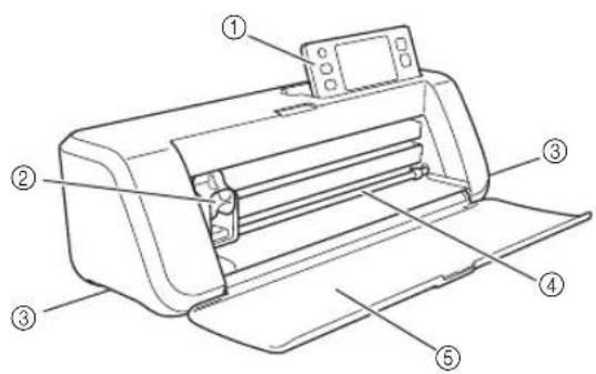
①Operation Panel
Allows you to control the unit and specify settings with the LCD panel and operating buttons. The angle of the operation panel can be adjusted to one of three levels. For details, see "Adjusting the Angle of the Operation Panel" on page 14.
②Carriage
Moves the installed holder for cutting or drawing.

①Holder
Installs in the carriage to cut or draw on craft paper or fabric. Use the holder designed specifically for cutting or drawing.
②Holder Guide
The guide secures the holder.
③Holder Lock Lever
Releases the holder when the lever is raised. Locks the holder when the lever is lowered.
③Handles
Grasped when moving the machine.
④Feed Slot
Feeds in or out a cutting/scanning mat. The mat is fed by the feed rollers on both sides.
⑤Front Tray Cover
Protects the feed rollers, carriage and holder. Open the cover while the machine is operating.
Unit Descriptions - Rear

①USB port (for a USB flash drive)
Allows a USB flash drive to be connected for saving and recalling data.
②USB port (for a computer)
Allows a USB cable to be connected for saving and recalling data. For Computers and Operating Systems, see "Connecting Your Machine to the Computer" on page 51.
③Slot
Allows a mat to be fed back and forth during an operation. Do not place any objects near the slot that would prevent the mat from being fed out.
④DC Power Jack
⑤AC Adapter
⑥AC Power Cord
⑦Scanner Glass (Bottom of Machine)
Unit Descriptions - Operation Panel

①Power Button
Turns the machine on/off.
②Home Button
Displays the home screen (starting screen for operating this machine).
③Settings Button
Displays the settings screen for specifying various settings. For details, see "Settings Screen" on page 30.
④LCD Panel
Displays operation screens, preview images of patterns and error messages.
⑤Feed Button
Feeds the loaded mat in to or out from the feed slot. Be sure to press this button to feed the mat when loading or unloading it.
⑥Start/Stop Button
Starts or stops cutting, drawing or scanning. When the button function is available, it lights up in green.
FIRST STEPS
The following procedures describe basic operations, from preparing the material to performing trial cutting.
Removing the Transport Packing Materials
Before turning on the machine, remove the shipping tape and the cardboard shock-absorbing material.

①Shipping tape
②Cardboard shock-absorbing material

Note
- If the packing materials were removed after the machine was turned on, turn the machine off, then on again. Continuing to use the machine without restarting it may result in incorrect operation.
Adjusting the Angle of the Operation Panel
The angle of the operation panel can be adjusted to one of three levels.

To store away the operation panel, first raise it until it is vertical, and then it can be lowered and stored away. If you wish to decrease the angle of the operation panel, raise it until it is vertical, and then adjust the angle again.
![graph TD A["Step 1"] --> B["Step 2"] B --> C["Step 3"] C --> D["Step 4"] D --> A](/content/2026/05/1011240/images/a3861767c82cb8f953aca5b9c42bc27291c70e1b0977d4b828b391da0a1b65a7.jpg)

Note
- Follow the instructions provided above to lower the panel. Lowering it forcibly may cause damage to the panel.
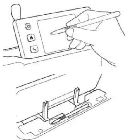
Using the Touch Pen and Spatula Stand (on certain models)
There is a touch pen and spatula stand behind the operation panel.

①Touch pen and spatula stand
Since the touch pen and spatula can stand in their holders, they can easily be used, for example, while cutting. The touch pen and spatula stand can also be removed and placed in any convenient location. The touch pen can be stored in its holder when it is not being used.
Turning On/Off the Machine
1 Connect the power cord to the AC adapter, and then connect the AC adapter to the machine.

①Power cord
②AC adapter

Memo
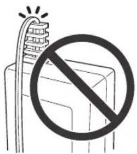
- When using the AC adapter, untie the bundled cord.
2 Plug the power cord into an electrical outlet.
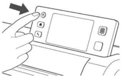
3 Press in the operation panel.
When the opening screen appears, touch anywhere on the display.
When the following message appears, touch the "OK" key.

The home screen appears.


Memo
- LCD panels commonly have bright spots (permanently lit dots) and dark spots (unlit dots). It may cause some unexpected luminous spots to appear and tiny picture elements to be missed in the screen. Please note that this is not a sign of malfunction.
4 To turn off the machine, press ① the operation panel.
5 Unplug the power cord from the electrical outlet.
6 Disconnect the AC adapter from the machine, and then disconnect the power cord from the AC adapter.

Note
- Do not wind the AC adapter cable around the adapter or bend the cable, otherwise the cable may be damaged.
Operation of LCD Panel
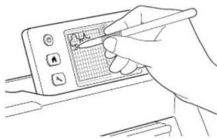
After the machine is turned on, the operation screens appear in the touch panel. To perform operations in the screens, use the included touch pen.


Note
- Never use a hard or pointed object, such as a mechanical pencil or screwdriver, to make a selection in the screens. Otherwise, damage to the machine may result.
Mat and Material Combinations
The recommended material thickness is 0.1 mm to 0.3 mm for paper and 0.2 mm to 1.5 mm for fabric. Refer to the following table for the appropriate mat and sheet for fabric cutting according to the material to be used for cutting or drawing. Depending on the machine model, some accessories listed in the chart may not be included. In that case, they must be purchased separately.
| Material and its thickness | Mat | Sheet for fabric cutting | ||||
| Standard mat | Low tack adhesive mat | Iron-on fabric appliqué contact sheet (white backing) | High tack adhesive fabric support sheet | |||
| Paper | Printer paper 80 g/m2(0.1 mm) | ∅ | √ | |||
| Scrapbook paper (thin) | 120 g/m2(0.15 mm) | √ | ||||
| Scrapbook paper (medium-thick) | 200 g/m2(0.25 mm) | √ | √* | |||
| Cardstock (thin) | 200 g/m2(0.25 mm) | √ | √* | |||
| Cardstock (medium-thick) | 280 g/m2(0.35 mm) | √ | √* | |||
| Vellum, tracing paper | 0.07 mm | √ | ||||
| Poster board (thin) | 280 g/m2(0.35 mm) | √ | √ | |||
| Poster board (thick) | 400 g/m2(0.5 mm) | √ | √ | |||
| Fabric | Thin cotton fabric (for quilt piece) | 0.25 mm | √ | √ | ||
| Thin cotton fabric (except for quilt piece) | 0.25 mm | √ | √ | |||
| Flannel (for quilt piece) | 0.6 mm | √ | √ | |||
| Flannel (except for quilt piece) | 0.6 mm | √ | √ | |||
| Felt 1 mm | √ | √ | ||||
| Denim 14 oz 0.75 mm | √ | √ | ||||
| Others | Plastic sheet (PP) 0.2 mm | √ | ||||
| Vinyl 0.2 mm | √ | |||||
| Magnet 0.3 mm | √ | |||||
| Sticker or seal 0.2 mm | √ | √ | ||||
* When cutting smooth paper

Note
- This chart is only a guide, always test material and mat strength prior to beginning project.
 Mat Mat |  | Sheet for fabric cuttingUse one of the following two sheets for fabric cutting when cutting fabric. | |
| Standard mat This is a mat with a high adhesive strength.Use this mat when cutting fabric.* Use the low tack adhesive mat with copy paper and smooth paper.Since the standard mat has a high adhesive strength, materials may remain stuck to the mat, causing the mat to become unusable. | Iron-on fabric appliqué contact sheet (white backing)(See page 19) | • Reinforces the fabric so that various patterns can be cut out.• Original texture may change because it remains attached to the back of fabric.* For use with the standard mat.* Do not place fabric backed with iron-on contact sheet directly onto a mat with high tack fabric support sheet. | |
| Low tack adhesive mat | This is a mat with a low adhesive strength. It is suitable for copy paper and smooth paper. | High tack adhesive fabric support sheet(See page 21) | • For best results when cutting fabric, attach the high tack adhesive fabric support sheet to the standard mat in order to increase the strength of the adhesive.• Depending on the shape, the pattern may not be cleanly cut. |

Note
- Avoid using craft paper or fabric covered with decorative layer (that can easily separate), such as lamé or foil. The separate layer may stick to the machine's scanning device or feed rollers during operation, resulting in damage to the machine. It may also damage the cutting blade. If such media is used or tested it is recommended to clean the scanner glass at the bottom of the machine after every use (page 79).

Memo
- When using a 12" × 12" (305 mm × 305 mm) mat, the maximum work area for cutting/drawing is 296 mm × 298 mm (11 3/4" × 11 3/4").
- When using an optional 12" × 24" (305 mm × 610 mm) mat, the maximum work area for cutting/drawing is 296 mm × 603 mm (11 3/4" × 23 3/4").
- Some fabrics with uneven surfaces can be cut if turned upside down.
Attaching the material to the mat
After preparing the mat and sheet (when cutting fabric) appropriate for the material, attach the material to the mat. For the mat and sheet appropriate for the material, see "Mat and Material Combinations" on page 16.
| Material Page | |
| Paper | Page 18 |
| Fabric (Other Than for Quilt Piecing) | Page 19 |
| Fabric (for Quilt Piecing) | Page 21 |
Paper

①Mat suitable for the material
□ Attaching the Material (Paper)
1 Peel off the protective sheet from the adhesive side of the mat.


Note
- Do not discard the protective sheet peeled off the mat; save it for later use.
• In order to maintain the adhesive strength, attach the protective sheet to the adhesive side of the mat after use. - When the mat is not being used, clean the adhesive side and affix the protective sheet before storing it. For details, see “Cleaning the Mat” on page 78.
2 Test attaching the material.
Before attaching the material to the mat, use a corner of the adhesive side of the mat to test attaching it. Check for the following when testing attaching the material.
- The color does not come off the material when it is peeled off.
- The material is not torn or deformed when it is peeled off.
If any problems occur when testing attaching, use different material.


Note
- Use the low tack adhesive mat with copy paper and smooth paper. Since the standard mat has a high adhesive strength, materials may remain stuck to the mat, causing the mat to become unusable
3 Attach the material to the mat's adhesive side.


Note
- Place the material within the attaching area (grid area) on the adhesive side. If the material extends from the attaching area, it may be damaged by the feed rollers when the mat is fed.

Memo
- The mat does not have a top and bottom. It can be inserted into the feed slot from either end.
4 Firmly attach all of the material to the mat so that there are no wrinkles and no part can curl off.
- Otherwise, curls in the material may become caught when the mat is inserted.
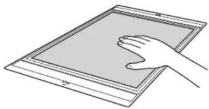

Note
- If the mat is dirty, clean it. For details, see "Cleaning the Mat" on page 78.
☐ Peeling Off the Material (Paper)
After cutting the material, use a spatula to slowly peel off the paper.

①Spatula
■Fabric (Other Than for Quilt Piecing)
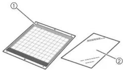
①Standard mat
②Iron-on fabric appliqué contact sheet (white backing)
□ Attaching the Material (Fabric Other Than for Quilt Piecing)
Iron the specially designed contact sheet to the back of fabrics for any use other than quilt piecing, and then attach them to the standard mat.
The double-faced adhesive type of the iron-on fabric appliqué contact sheet reinforces the fabric and enables any pattern to be cut easily, including appliqués.
The sheet cannot be removed once it has been attached to the back of fabrics. For quilt piecing, use the high tack adhesive fabric support sheet and avoid using the iron-on fabric appliqué contact sheet.

Note
- The contact sheet may not adhere to a fabric surface that is so rough that the two surfaces cannot be heat-set to adhere to each other.
① Peel off the protective sheet from the adhesive side of the standard mat.
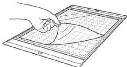

Note
- Do not discard the protective sheet peeled off the mat; save it for later use.
- In order to maintain the adhesive strength, attach the protective sheet to the adhesive side of the mat after use.
- When the mat is not being used, clean the adhesive side and affix the protective sheet before storing it. For details, see “Cleaning the Mat” on page 78.
2 Cut the iron-on fabric appliqué contact sheet to a size 2 cm or more larger than the outline of the pattern to be cut.

①Pattern to be cut
②Cutting line of sheet
③Margin of 2 cm or more
③ With the glossy side of the contact sheet facing down, place it on the wrong side of the fabric.
Be sure to first iron the fabric to remove any wrinkles. Before placing the contact sheet on the fabric, make sure that the fabric has been allowed to cool after ironing.

①Glossy side of contact sheet
②Wrong side of fabric
4 Evenly iron the entire contact sheet to affix it to the wrong side of the fabric.
With the iron on a medium temperature setting (140 to 160 °C (284 °F to 320 °F)), press each part of the sheet for about 20 seconds (the length of time differs depending on the material).
Be sure to apply pressure on the top of the backing and push out any air between the sheet and fabric.

①Backing

Note
- Before attaching the contact sheet to the fabric, use a piece of the sheet to test attaching it. If any problems occur when testing attaching, use different material.
• Leaving the iron in the same place for too long may scorch or melt the material.
5 Peel off the backing from the contact sheet.
Before peeling off the backing, allow all parts to cool.
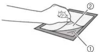
①Contact sheet
②Backing
6 With the side of the fabric that the contact sheet is attached to facing down, attach the material to the mat from its edges.
Slowly attach the material from its edges so that no air is trapped between it and the mat.


Note
- Place the material within the attaching area (grid area) on the adhesive side. If the material extends from the attaching area, it may be damaged by the feed rollers when the mat is fed.

Memo
- The mat does not have a top and bottom. It can be inserted into the feed slot from either end.
- Be sure that the vertical grain of the attached fabric runs straight up and down. The built-in patterns are automatically arranged suitable for fabric with vertical grain.
7 Firmly attach all of the material to the mat so that there are no wrinkles and no part can curl off.
- Otherwise, curls in the material may become caught when the mat is inserted.
☐ Peeling Off the Material (Fabric Other Than for Quilt Piecing)
After cutting the material, use a spatula to peel off the fabric together with the attached contact sheet.

①Pattern that was cut out
②Contact sheet
③Spatula

Note
- Do not place anything heated on the fabric attached with a contact sheet. Adhesive will permeate any other pieces of fabric around.
□ Attaching Fabrics With the Double-Sided Adhesive
Place a cutout on a base fabric and apply pressure on the top of the cutout using an iron. (The contact sheet may not adhere well to some fabrics.) Hand or machine stitch to ensure that the cutout stays in place.

①Base fabric
②Cutout with a contact sheet

Note
- Do not wash fabrics attached together with a double-sided adhesive contact sheet.
- When attaching fabrics with the double-sided adhesive, iron carefully, being sure that the material and adhesive surfaces are properly heat-set.
- When attaching fabrics of different weights with the double-sided adhesive, first iron the lighter-weight fabric to affix the contact sheet.
☐ Notice on Use of Iron-on Fabric Appliqué Contact Sheet
- Store the contact sheet at room temperature and in a location not exposed to high temperatures, high humidity or direct sunlight.
■Fabric (for Quilt Piecing)

①Standard mat
②High tack adhesive fabric support sheet
☐ Attaching the Material (for Quilt Piecing)
Use the high tack adhesive fabric support sheet to attach fabrics for quilt piecing to the standard mat. These sheets should only be used with patterns that have a seam allowance. The high tack adhesive fabric support sheet can be repeatedly used until their adhesive strength has decreased. (Once the support sheet has been peeled off the mat, it can no longer be used.)
① Peel off the protective sheet from the adhesive side of the standard mat.
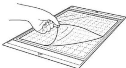

Note
- Do not discard the protective sheet peeled off the mat; save it for later use.
- In order to maintain the adhesive strength, attach the protective sheet to the adhesive side of the mat after use.
- When the mat is not being used, clean the adhesive side and affix the protective sheet before storing it. For details, see "Cleaning the Mat" on page 78.
2 With the glossy side of the high tack adhesive fabric support sheet facing down, attach it to the mat's adhesive side.
Slowly attach the support sheet from its edges so that no air is trapped between the mat and the sheet.
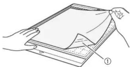
①Glossy side of support sheet

Note
- Place the support sheet within the attaching area (grid area) on the adhesive side of the mat. If the sheet extends from the attaching area, it may be damaged by the feed rollers when the mat is fed.
③ Peel off the backing from the top of the support sheet.

①Backing ②Adhesive
4 Test attaching the material.
Before attaching the material to the mat, use a corner of the adhesive side of the mat to test attaching it. If any problems occur when testing attaching, use different material.

5 From its edges, attach the material to the adhesive side of the mat so that there are no wrinkles in the material.
Be sure to first iron the fabric to remove any wrinkles.


Note
- Place the material within the attaching area (grid area) on the adhesive side. If the material extends from the attaching area, it may be damaged by the feed rollers when the mat is fed.

Memo
- The mat does not have a top and bottom. It can be inserted into the feed slot from either end.
- Be sure that the vertical grain of the attached fabric runs straight up and down. The built-in patterns are automatically arranged suitable for fabric with vertical grain.
- When drawing a seam allowance, attach the fabric to the mat with its wrong side facing up.
6 Firmly move the spatula handle across the surface of the fabric to remove any wrinkles and firmly attach the fabric to the mat.

①Spatula
☐ Peeling Off the Material (Fabric for Quilt Piecing)
After cutting the material, use a spatula to slowly peel off just the fabric. Try not to peel off the support sheet.
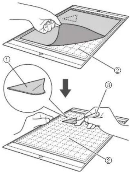
①Fabric cut out
②Support sheet remaining on mat
③Spatula

Note
- The support sheet may be unintentionally peeled off while you are removing the fabric from the mat under the following conditions:
- The adhesive between the mat and support sheet is becoming weak after repeated uses.
- The support sheet tends to be strongly attached to a certain types of fabrics. In this case, use the included spatula to hold the support sheet on the mat and remove the fabric using your hand.
• After cutting, carefully remove any fibers remaining on the support sheet. - When attaching fabric with an iron-on sheet attached or paper to the mat, cleanly peel off the support sheet from the mat, or attach the material to a different standard mat without a support sheet attached.
- Do not leave material attached to a mat with a support sheet attached for a long period of time; otherwise, the adhesive will permeate the material.
☐ Notice on Use of High Tack Adhesive Fabric Support Sheet
- When the sheet's adhesive strength decreases or fabric becomes twisted while being cut, replace the sheet with a new one.
- When peeling the sheet off the mat or replacing the sheet, use the spatula to carefully remove the old sheet.
- Store the mat in between uses with the protective sheet affixed to the support sheet.
- If a mat with a support sheet attached is not to be used for a certain length of time, peel the support sheet off the mat and affix the protective sheet on the adhesive side of the mat before storing it.
- Do not reuse a support sheet that has been attached to the mat.
- Store the support sheet at room temperature and in a location not exposed to high temperatures, high humidity or direct sunlight.
- Do not bend the support sheet to store it.
Adjusting the Blade Extension
The appropriate blade extension differs depending on the material type and thickness. Before installing the holder in the carriage, turn the holder cap to adjust the blade extension, and then perform trial cutting. For details on trial cutting, see “Trial Cutting” on page 27.
■Cutting Settings
Use the following table to select the appropriate settings according to the material that will be cut.
| Material and its thickness | Blade scale setting*Half cut | Cut pressure setting | Cutting blade | |||
| Standard cut blade(turquoise) | Deep cut blade(purple) | |||||
| Paper | Printer paper 80 g/m2(0.1 mm) 3 -1 | √ | ||||
| Scrapbook paper (thin) | 120 g/m2(0.15 mm) | 3.5 0 | √ | |||
| Scrapbook paper(medium-thick) | 200 g/m2(0.25 mm) | 4 0 | √ | |||
| Cardstock (thin) | 200 g/m2(0.25 mm) | 4 0 | √ | |||
| Cardstock (medium-thick) | 280 g/m2(0.35 mm) | 5 0 | √ | |||
| Vellum, tracing paper 0.07 mm 3 0 | √ | |||||
| Poster board (thin) | 280 g/m2(0.35 mm) | 5.5 0 | √ | |||
| Poster board (thick) | 400 g/m2(0.5 mm) | 7.5 4 | √ | |||
| Fabric | Thin cotton fabric (for quilt piece) | 0.25 mm 4 4 | √ | |||
| Thin cotton fabric(except for quilt piece) | 0.25 mm 4 4 | √ | ||||
| Flannel (for quilt piece) | 0.6 mm 6.5 4 | √ | ||||
| Flannel (except for quilt piece) | 0.6 mm 6.5 4 | √ | ||||
| Felt 1 mm 5 5 | √ | |||||
| Denim 14 oz 0.75 mm 5.5 6 | √ | |||||
| Others | Plastic sheet (PP) | 0.2 mm 4 0 | √ | |||
| Vinyl 0.2 mm 4 0 | √ | |||||
| Adhesive Craft Vinyl(backing sheet :0.1 mm) | 0.07 mm | 1.5 * | -1 | √ | ||
| Magnet 0.3 mm 5.5 0 | √ | |||||
| Sticker or seal | 0.2 mm 4 0 | √ | ||||
| Sticker Sheet (backingsheet : 0.15 mm) | 0.15 mm | 2 * | -1 | √ | ||
- Adjust the setting for "Cut Pressure" in the settings screen (page 30).
- Use a high tack adhesive fabric support sheet or a iron-on fabric appliqué contact sheet when you cut a piece of fabric out. For details, see “Mat and Material Combinations” on page 16.

Note
- The settings indicated in the table are approximations. The setting will differ depending on the type and thickness of the material to be cut. Be sure to perform a trial cutting first.
Appropriate Blade Extension
Adjust the blade extension to slightly exceed the thickness of the material that will be cut. Use the markings on the holder to make the adjustment.

①End of holder cap
②Material that will be cut
③Length of blade tip

Note
- Be careful that the blade does not extend too much. The blade can cut even though it only slightly extends from the holder. If too much of the blade extends, it may break.
■Adjusting the Cutting Blade
1 Remove the protective cap.
• After use, be sure to retract the blade into the holder and attach the protective cap.
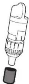

CAUTION
- Do not allow infants/children to put the protective caps in their mouths.
2 With the reference line on the holder facing toward you, fully turn the cap to the right to extend the blade tip to its maximum.
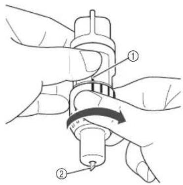
①Reference line
② Extend the blade tip to its maximum.
Check the thickness of the material, and then adjust the blade extension. See "Cutting Settings" on page 24.
The larger the holder scale setting, the further the blade extends.

①Turn to the left to decrease the blade extension.
②Turn to the right to increase the blade extension.
Installing and Uninstalling the Holder
After adjusting the blade extension, install the holder in the machine. For the blade extension appropriate for the material, see "Adjusting the Blade Extension" on page 24.
① Press in the operation panel to turn on the machine.
For details, see "Turning On/Off the Machine" on page 15.

Note
- Be sure to turn on the machine before installing the holder.
- If the holder is installed while the machine is off, the blade may break and material may not be cut cleanly.
2 If the holder lock lever is not raised, raise it.
The holder cannot be installed if the lever is lowered.
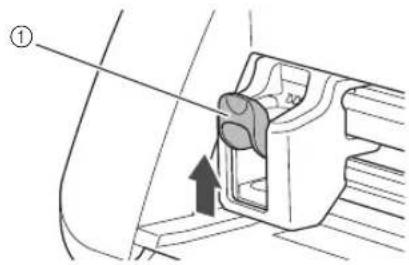
①Holder lock lever
CAUTION
- Please remove protective cap from blade holder before placing it into the machine carriage.
- Do not allow infants/children to put the protective caps in their mouths.
3 Grasp the holder grip, and then insert the holder into the carriage.

①Grip
4 Push down on the holder lock lever.
Firmly push down until the holder is locked in place.
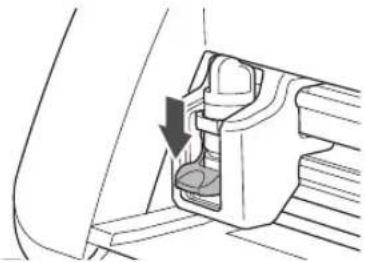
5 Reverse the installation procedure to uninstall the holder.
CAUTION
• After removing the blade holder from the machine, be sure to retract the blade into the holder and attach the protective cap.
- Do not leave the blade extended. Otherwise, injuries may result.
- Do not allow infants/children to put the protective caps in their mouths.
Trial Cutting
Make sure that the blade extension is appropriate for the material. Using the same material to cut or draw on in your project, perform trial cutting.
■Turning On the Machine
Press ① the operation panel to turn on the machine.
- For details, see "Turning On/Off the Machine" on page 15.
■Setting the Holder
Install the cutting blade holder into the carriage of the machine.
- For details, see "Installing and Uninstalling the Holder" on page 26.
■Selecting the Test Pattern
Cut out a test pattern from paper.

Memo
- The language setting can be specified in the settings screen (see "Language" on page 30).
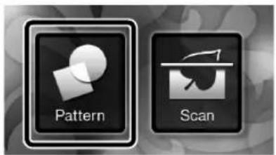
1 Select "Pattern" in the home screen.

② Touch the "Test" key in the pattern category selection screen.

③ Select a pattern in the pattern selection screen.
- We recommend using pattern "T-02" when cutting paper and pattern "T-03" when cutting fabric.
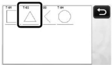
④ Touch the "Set" key.

5 Check the pattern arrangement, and then touch the "OK" key.

- For details on changing the pattern arrangement, see "Pattern Layout Screen" on page 43.
- Press to cancel the pattern selection, and then select the pattern again.
■Loading the Mat
1 Attach the material that will be cut to the mat.
- For details on attaching material to the mat, see "Attaching the material to the mat" on page 18.
2 While holding the mat level and lightly
inserting it into the feed slot, press the operation panel.
Lightly insert the mat so that it aligns with the guides on the left and right sides of the feed slot and is tucked under the feed rollers.
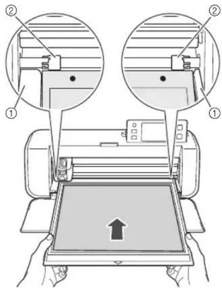
①Guides
②Feed rollers

The mat is fed in to complete the preparations for cutting.
Cutting
1 Select "Cut" in the draw/cut selection screen.

The "Start/Stop" button in the operation panel lights up.

Note
- Make sure that patterns that will be cut out are arranged in the cutting area corresponding to the size of the material attached before continuing operation.
2 Adjust the cutting speed and pressure.
Before cutting the pattern, adjust the cutting speed and pressure. These adjustments can be made from the settings screen. Press in the operation panel and touch to display the second page of the settings screen.
▶ Touch + or to change the settings and then touch the "OK" key.
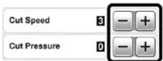

Note
- Depending on the fabric being used, it may not be cut cleanly if the cutting pressure is not correctly adjusted. For the appropriate cutting pressure, see "Cutting Settings" on page 24.
③Press the "Start/Stop" button to start cutting.

When cutting is finished, the message "Finished cutting." appears on the display. Touch the "OK" key to return to the draw/cut selection screen.
■Unloading the Mat
① Press in the operation panel to feed out the mat.

2 Peel off the material from an area that is easily removable, such as a corner, and then slowly peel while maintaining an even pressure.

3 Holding the mat with your hand, use the included spatula to carefully peel off the cut-out patterns.

①Spatula

Note
- For instructions on how to peel off the material, see also "Mat and Material Combinations" on page 16.
■Checking the Trial Cutting Results
Adjust the blade extension according to the trial cutting results.
Repeatedly perform trial cutting and adjust the blade extension until the material is cut cleanly.
☐ With an Appropriate Blade Extension
When the material is peeled off, a faint trace of the cut remains on the mat surface.
![graph TD A["Triangle"] --> B["Grid Grid"] style A fill:#fff,stroke:#000 style B fill:#fff,stroke:#000](/content/2026/05/1011240/images/be021c152a0db211125a6e3225100314faabc5ccba40969aa7fc6a98834b302e.jpg)
☐ With a Blade Extension That Needs to be Adjusted
| Trial cutting results | Tips for adjustment |
| Part of the cut material remains when it is peeled off. | Too Little of a Blade Extension: Turn the holder cap half a marking to the right. (2) |
| The material is not clearly cut. | Too Little of a Blade Extension: Turn the holder cap one marking to the right. (2) |
| There are deep cuts completely through the mat. | Too Much of a Blade Extension: Turn the holder cap one marking to the left. (1) |


Note
- Be careful that the blade does not extend too much. Otherwise, the blade may break. If there is too much of a blade extension, the material may not be cut cleanly and the mat will deteriorate quicker.
Settings Screen
From the LCD panel, the settings for specific functions can be selected and settings can be adjusted. To display the settings screen, press in the operation panel.
Page 1
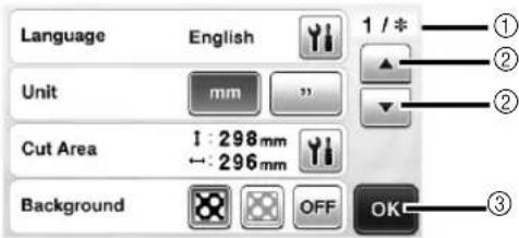
①Settings screen page number
②Touch to display a different page.
③Touch to finish specifying settings.
Language
Select the display language. Touch Select the desired display language, and then touch the "OK" key.
Unit
Select either millimeters or inches as the displayed measurement units.
Cut Area
Specify the area for cutting/drawing according to the size of material to be used. Touch and then touch and drag the area resizing keys to specify the area. When using a 12" × 24" (305 mm × 610 mm) mat, touch the mat size key to select a larger mat size, and then specify the area size. When using a 12" × 12" (305 mm × 305 mm) mat, change the setting for "Cut Area" again.

①Area resizing key (Using the touch pen, touch the key, and then drag it around the screen to specify the area.)

②Mat size key (Touching the key switches between the mat size 12" × 12" (305 mm × 305 mm) and 12" × 24" (305 mm × 610 mm).)
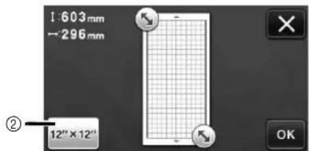
- Touch the "OK" key to apply the settings. Touch ✗ turn to the previous screen without applying the settings.
Background
Adjust the contrast of a background image scanned with the background scanning function. For details, see "Scanning a Background Image" on page 47.
Page 2
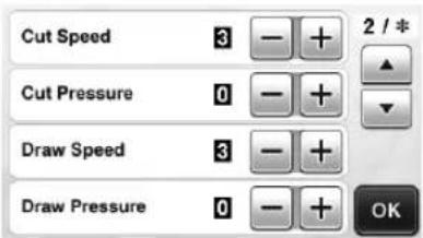
Cut Speed
Adjust the cutting speed.
Cut Pressure
Adjust the cutting pressure. For the appropriate cutting pressure, see "Cutting Settings" on page 24.
Draw Speed
Adjust the drawing speed.
Draw Pressure
Adjust the drawing pressure. Adjustments to the drawing pressure will affect the finished product. Use the same material that the pattern will be drawn on to make the adjustments in advance. If the pressure is too high, the pen tip may be damaged. Adjust the pressure appropriately.
Page 3
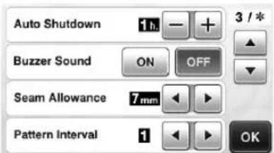
Auto Shutdown
Specify the length of time for the auto shutdown function. The setting can be specified in 1-hour increments. For details, see "Auto Shutdown" on page 32.
Buzzer Sound
Select whether or not an operation sound is produced, for example, when a key is touched.
Seam Allowance
Specify the seam allowance. This is applied when drawing on fabric, then cutting it, for example, when making quilt pieces. For details, see “Cutting Around Drawings” on page 57.

Memo
- When multiple patterns are cut at the same time, the setting specified in this screen is applied to all patterns.
- If cutting line data saved with a different seam allowance is imported and used, the setting specified in this screen will have priority over the saved setting.
Pattern Interval
Specify the spacing between patterns as well as white space around the edges of cutting area when patterns in the pattern layout screen are automatically arranged. The larger the number setting, the further spacing between patterns.

Note
- Set the number to "3" or higher when lightweight fabric is attached to the mat with a high tack adhesive fabric support sheet.
Page 4
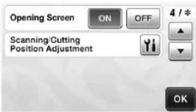
Opening Screen
Select whether the opening slide show is displayed after the machine is turned on. If the slide show is displayed, touch the screen to display the home screen.
Scanning/Cutting Position Adjustment
The scanning/cutting position can be adjusted. To adjust the position, touch 📋 display the settings screen. For details, see “Adjusting the Scanning/Cutting Position” on page 81.
Page 5
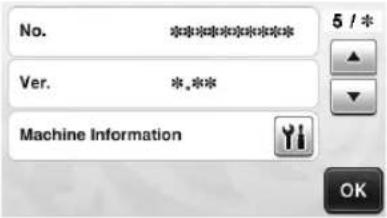
No.
Displays the serial number specific for this machine.
Ver.
Displays the version information for this software.
Machine Information
Touch ,this page displays machine information.
■Page 6 (Wireless network models only)

Network
Touch 📁 set up a wireless network. For details, refer to "Wireless Network Setup Guide".
■Page 7 (Wireless network models only)

ScanNCut Online
Touch the "Register" key to set up ScanNCut Online. For details, refer to "Wireless Network Setup Guide".
Auto Shutdown
If the machine is not used for a specified length of time, it will automatically turn off. The length of time until the machine turns off can be specified in the settings screen.

Auto Shutdown

If the machine is automatically turned off after you reach the pattern layout screen, the stored information can be recalled when the machine is turned on again. Following the instructions in the message screen that appear when the machine is turned on again, touch the "OK" key to display the pattern layout screen or touch the "Cancel" key to return to the home screen.
![graph TD A["OK to retrieve and resume previous memory?"] --> B["Cancel"] B --> C["OK"] C --> D["Add"] D --> E["Save"] E --> F["OK"] F --> G["Pattern"] F --> H["Scan"]](/content/2026/05/1011240/images/b8b7d2b251629ad00fa5752f6a0055b48a73528db07196057cfee0dd822bf1d4.jpg)
①Message screen
②Pattern layout screen
③Home screen
If the machine is automatically turned off before you reach the pattern layout screen, the home screen will be displayed when the machine is turned on again.
PATTERN CUTTING
The following procedures use built-in patterns to describe the entire series of operations, from selecting a pattern and editing it to cutting.
Tutorial 1 - Cutting Patterns
![graph TD A["Star"] --> B["Star"] C["Cliver"] --> D["Star"] style A fill:#f9f,stroke:#333 style B fill:#ccf,stroke:#333 style C fill:#cfc,stroke:#333 style D fill:#fcc,stroke:#333](/content/2026/05/1011240/images/669e98298c2dae2a1283ba0a8c818e0d8672b257a8d5e7d930b7a74def2aa4d9.jpg)
In this tutorial, we will cut two built-in patterns.
■Turning On the Machine
Press to turn on the machine.
- For details, see "Turning On/Off the Machine" on page 15.
■Setting the Holder
Install the cutting blade holder into the carriage of the machine.
- For details, see "Installing and Uninstalling the Holder" on page 26.
■Selecting and Editing the First Pattern
1 Select "Pattern" in the home screen.

2 Select the category for the pattern to be cut out in the pattern category selection screen.
For this example, select


①Touch to return to the previous screen. ②Pattern categories
Memo
- The pattern categories and built-in patterns that appear in the operation screens differ depending on the machine model. For details on the built-in patterns, refer to the included "Pattern List".
3 Select the first pattern to be used in the pattern selection screen.
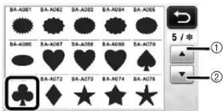
①Touch to scroll up. ②Touch to scroll down.
4 Edit the pattern using the pattern editing screen.
After editing is finished, touch the "Set" key. - For details on the editing functions, see "Pattern Editing Functions" on page 41.
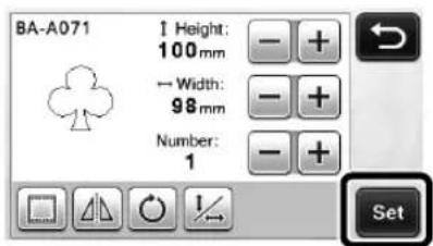
■Selecting and Editing the Second Pattern
① Touch the "Add" key in the pattern layout screen.

The pattern category selection screen appears.
- Press to cancel the pattern selection, and then select the pattern again.
2 Select the category for the pattern to be cut out.

①Touch to return to the previous screen.
3 Select the second pattern to be used.
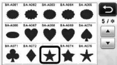
4 Edit the pattern.
After editing is finished, touch the "Set" key.
- For details on the editing functions, see "Pattern Editing Functions" on page 41.

5 Check the pattern arrangement.
The two patterns that will be cut out appear in the pattern layout screen. After checking the arrangement, touch the "OK" key.
- From this screen, an individual pattern can be edited, moved or deleted. For details on the functions that can be used in the pattern layout screen, see "Layout Editing Functions" on page 43.
- By using the auto layout function, the arrangement of the patterns can easily be adjusted. For details, see "Auto Layout Functions" on page 46.
- Select the "Cut Area" setting appropriate for the mat being used. (See page 30.)
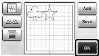
The draw/cut selection screen appears.

Note
- Depending on the pattern type and material to be cut, the patterns may not be cleanly cut if their spacing is too small. In that case, rearrange the patterns to separate them.

Memo
• To move a pattern within the cutting/drawing area, touch the pattern on the screen and drag it to the desired position.

- To delete a pattern from the arrangement, select the pattern in the layout editing screen, and then use the function for deleting.
▶ Touch in the pattern layout screen.
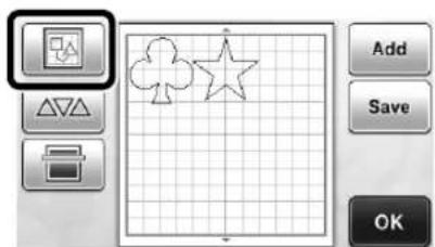
▶ Touch the pattern to be deleted in the screen. To delete multiple patterns, use the function for selecting multiple patterns. For details, see "Selecting Multiple Patterns" on page 39.
▶ Touch the layout editing screen to delete the selected pattern(s).

■Loading the Mat
While holding the mat level and lightly inserting it into the feed slot, press the operation panel.
- For details, see "Loading the Mat" on page 27.
Cutting
1 Select "Cut" in the draw/cut selection screen.

The "Start/Stop" button in the operation panel lights up.
- Before cutting your project, adjust the blade extension appropriately. For details, see "Adjusting the Blade Extension" on page 24.

Note
- Before continuing operation, make sure that patterns that will be cut out are arranged in the cutting area corresponding to the size of the material to be used.
② Adjust the cutting speed and pressure.
Before cutting the pattern, adjust the cutting speed and pressure. These adjustments can be made from the settings screen. Press in the operation panel.
▶ Touch + or to change the settings.


Note
- Depending on the fabric being used, it may not be cut cleanly if the cutting pressure is not correctly adjusted. For the appropriate cutting pressure, see "Cutting Settings" on page 24.
3 Press the "Start/Stop" button to start cutting.
When cutting is finished, the draw/cut selection screen appears again.
■Unloading the Mat
Feed out the mat, and then use the included spatula to peel off the patterns.
For details, see "Unloading the Mat" on page 28.

Tutorial 2 - Cutting Advanced Patterns
![graph TD A["Crown Shape"] --> B["Base"] C["Crown Shape"] --> D["Base"] E["Crown Shape"] --> F["Base"] G["Crown Shape"] --> H["Base"] I["Crown Shape"] --> J["Base"] K["Crown Shape"] --> L["Base"] M["Crown Shape"] --> N["Base"] O["Crown Shape"] --> P["Base"] Q["Crown Shape"] --> R["Base"] S["Crown Sha…](/content/2026/05/1011240/images/3dc588fe4072f55d4089eefa3548e458b0c0049edb579b6472813d3dc7443191.jpg)
In this tutorial, we will cut a built-in pattern in the

category.
■Selecting and Editing the First Pattern Piece
1 Select "Pattern" in the home screen.
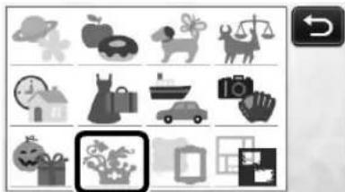
2 Select the category in the pattern category selection screen.
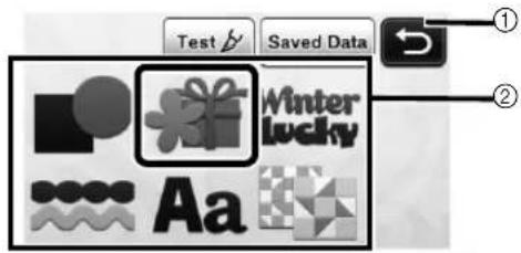
①Touch to return to the previous screen.
②Pattern categories

Memo
- The pattern categories and built-in patterns that appear in the operation screens differ depending on the machine model. For details on the built-in patterns, refer to the included "Pattern List".
3 Select the sub-category in the pattern sub-category selection screen.
4 Select the pattern to be cut out in the pattern selection screen.

①Touch to scroll up.
②Touch to scroll down.
5 Edit the size of the entire pattern using the pattern sizing screen.
After editing is finished, touch the "OK" key.
- For details on the pattern sizing screen, see "Pattern Sizing" on page 42.

6 Select the piece to be edited first in the pattern piece list screen, and then touch the "OK" key.
From the pattern piece list that appears in the screen, touch a pattern piece to edit it individually.


Memo
- The pattern pieces displayed in the pattern piece list screen are automatically arranged so that the grain is vertical when fabric is used as the material for cutting. Therefore, the angle at which the pattern appears in the pattern piece list may differ from the actual angle of the pattern piece to be cut out.

①Appearance in pattern piece list
②Actual arrangement of the pattern piece to be cut out
- Change the angle of pattern piece using the rotating function according to your project. For details, see "Editing the Pattern Piece" on page 42.
⑦ Edit the pattern piece using the pattern piece editing screen.
After editing is finished, touch the "Set" key.
- For details on the editing functions, see "Editing the Pattern Piece" on page 42.

8 Check the pattern piece arrangement using the pattern layout screen.
The pattern piece to be cut out appears in the screen. After checking the arrangement, touch the "OK" key.
- From this screen, an individual pattern piece can be edited, moved, deleted or saved. For details on the editing functions in the pattern layout screen, see "Pattern Layout Screen" on page 43.
- Select the "Cut Area" setting appropriate for the mat being used. (See page 30.)

The draw/cut selection screen appears.
■Loading the Mat
Attach the material that the first pattern piece will be cut out of to the mat, and then feed in the mat from the feed slot.
When cutting a pattern consisting of multiple pieces in different colors, edit the pattern piece for each color, and then change the material to cut out each piece.
- For details on preparing the material and loading the mat, see "Loading the Mat" on page 27.
■Cutting the First Pattern
1 Select "Cut" in the draw/cut selection screen.

The "Start/Stop" button in the operation panel lights up.

Note
- Before continuing operation, make sure that patterns that will be cut out are arranged in the cutting area corresponding to the size of the material to be used.
2Press the "Start/Stop" button to start cutting.
After the first pattern piece has been cut out, the following message appears. In order to cut out the second pattern piece, touch the "Select the next part" key.

Touching the "Select the next part" key erases all editing information for the first pattern piece and displays the pattern piece list screen again.
■Unloading the Mat
① Press in the operation panel to feed out the mat.
In order to replace the material with one of a different color, the material used for the first pattern piece must be fed out.

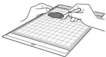
2 Peel from the mat the pattern piece that was cut out.
For details on peeling the material from the mat, see "Unloading the Mat" on page 28.
■Editing and Cutting the Second Pattern Piece
1 Select and edit the second pattern piece, and then touch the "OK" key.
For details on editing the pattern, follow steps 6-8 (page 36) in "Selecting and Editing the First Pattern Piece".
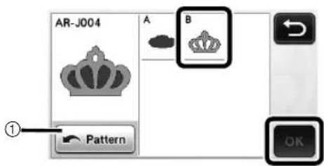
①Touch to return to the pattern category selection screen for selecting another pattern.
2 Follow the procedures described in "Loading the Mat" (page 27) and "Cutting" (page 28) to load the material to be used for the second pattern piece and cut it out.
When cutting is finished, a message appears.
3 After all pattern pieces have been cut out, touch the "Finish" key.
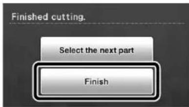
The draw/cut selection screen appears again.
■Unloading the Mat
Peel from the mat the pattern piece that was cut out. For details on peeling the material from the mat, see "Unloading the Mat" on page 28.

PATTERN SELECTION
Four pattern selection functions are available in the layout editing screen depending on your preference.
▶ Touch in the pattern layout screen to use the pattern selection functions.
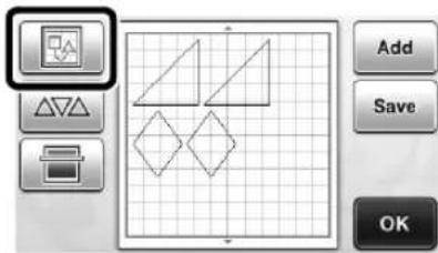
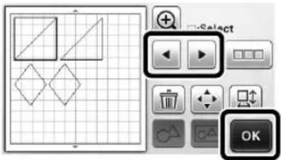
Selecting a Single Pattern
Select an individual pattern to be edited by either touching it in the editing screen or using and
▶, and then touch the "OK" key. The selected pattern is surrounded with a red box.
Selecting Multiple Patterns
■Selecting Desired Patterns
① Touch in the layout editing screen for making multiple pattern selection.

2 Individually touch all the patterns you want to select in the screen, and then touch the "OK" key.
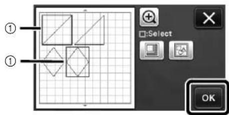
①Selected patterns

Memo
- Touching a selected (surrounded with a red box) pattern again clears its multiple selection.
- Touching any blank space in the screen clears all the pattern selections.
■Selecting All Patterns
① Touch in the layout editing screen for making multiple pattern selection.
② Touch to select all the patterns on the screen.

3 Check the selection, and then touch the "OK" key.
All the selected patterns are surrounded with a red box.

■Specifying the Selection Area
① Touch in the layout editing screen for making multiple pattern selection.
2 Touch for specifying an area to select the patterns.

3 Touch and drag the area resizing keys to specify the area, and then touch the "OK" key.

①Keys for specifying the area
②Patterns to be selected

Note
- This method of selecting patterns within a specified area is useful for welding or unifying patterns and deleting unwanted images when scanning (page 71).
Chapter 3 ADVANCED OPERATIONS
CUTTING AND EDITING FUNCTIONS
Pattern Editing Functions
The pattern editing functions available may differ depending on the pattern you select. Follow the instructions in either this section or "Pattern Editing Functions - Advanced Patterns" on page 42.
Available in the following screen
Pattern editing screen
→Tutorial 1; Step 4 (page 33) in "Selecting and Editing the First Pattern"
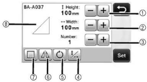

Note
- Depending on the pattern being used, the material may not be cut cleanly, if reducing the size of the pattern. Before making your project, perform trial cutting with the same material.
①Sizing (Height)
Edit the pattern height while maintaining the aspect
ratio. Touch ☐ to adjust the setting. Touch

to edit only the height.
![graph TD A["Right Triangle"] <--> B["Right Triangle"] C["Left Triangle"] <--> D["Right Triangle"] E["Control Button -"] --> F["+"] G["Control Button +"] --> H["+"]](/content/2026/05/1011240/images/6d7a7da2fdb4eb9ee4f705747626bee6876940bc6279b062bf0fae50394d20cb.jpg)
②Sizing (Width)
Edit the pattern width while maintaining the aspect ratio. Touch ☐ to adjust the setting. Touch

to edit only the width.

③Duplicating
Create a duplicate of the pattern. Touch to specify the number of pattern duplicates to be created.

④ Unlocking the Aspect Ratio
Touch to edit the pattern size without maintaining the aspect ratio. The function is available depending on the pattern you select. If the key is not available, the aspect ratio is locked and the pattern can only be edited while maintaining the aspect ratio.
⑤Rotating
Rotate the pattern.

Touch the key for the desired angle.
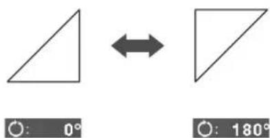
⑥Mirroring
Flip the pattern along a vertical axis.
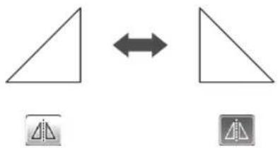
⑦Seam Allowance
Apply the seam allowance setting. Apply this setting when cutting around a drawn pattern, such as when making appliqué or quilt pieces. When applied, the drawing line (blue) and cutting line (black) appear.
- For details on the seam allowance function, see "Cutting Around Drawings" on page 57.


Memo
- Depending on the pattern, the seam allowance may be applied as a default. Check the setting.
⑧Previewing
Display a preview of the edited pattern.
Pattern Editing Functions - Advanced Patterns
The pattern editing functions available may differ depending on the pattern you select. Follow the instructions in either this section or "Pattern Editing Functions" on page 41.
Pattern Sizing
Available in the following screen
| Pattern sizing screen | →Tutorial 2; Step 5 (page 36) in “Selecting and Editing the First Pattern Piece” |
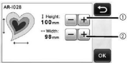
①Touch to edit the pattern height (while maintaining the aspect ratio).
②Touch to edit the pattern width (while maintaining the aspect ratio).

Memo
- All the pattern pieces displayed on the pattern sizing screen can be resized while maintaining the aspect ratio.
■Editing the Pattern Piece
Available in the following screen
| Pattern piece editing screen | →Tutorial 2; Step 7 (page 37) in “Selecting and Editing the First Pattern Piece” |

①Duplicating
②Rotating
③Mirroring
④Seam Allowance
- For details on using each key, see "Pattern Editing Functions" on page 41.
Pattern Layout Screen
The arrangement of the patterns can be edited. The cutting/drawing area specified with the "Cut Area" setting (page 30) in the settings screen is displayed in the preview screen. Edit the pattern arrangement so that the patterns fit within the specified area.
Available in the following screen
| Pattern layout screen | →Tutorial 1; Step 5 (page 34) in “Selecting and Editing the Second Pattern” |

①Adding Patterns
Add a pattern to the layout.
▶ Touching this key displays the pattern category selection screen. From that screen, select the pattern to be added.
②Saving
Save the pattern arrangement as data. For details, see "Saving" on page 50.
③Editing
The patterns in the layout can be edited, moved or deleted. For details, see "Layout Editing Functions" on page 43.
④Auto Layout
Automatically arrange the patterns to reduce their spacing. For details, see "Auto Layout Functions" on page 46.
⑤Background Scanning
Scan the material for cutting/drawing to be displayed in the background of the pattern layout screen. You can use specific areas of the material to cut out/draw patterns, or display the material that has already been cut in order to reuse it. For details, see "Scanning a Background Image" on page 47.
Layout Editing Functions
The layout editing functions are available when

is touched in the pattern layout screen.

The layout editing screen appears.
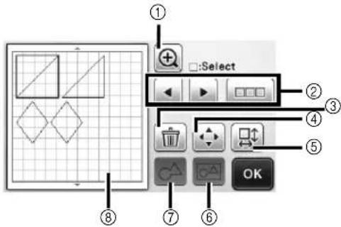
①Magnifying
Zoom in on the pattern at 200%. Then, touch
200% to display the patterns enlarged by 400%. To scroll through the screen, touch the arrow keys.

②Selecting Patterns
Select an individual pattern or multiple patterns to be edited. For details, see "PATTERN SELECTION" on page 39.
③Deleting
Delete the selected patterns.
④Moving
Incrementally move the selected patterns. Touch the arrow keys to adjust the position of the patterns.


Memo
- The pattern can also be moved by touching it displayed in the layout editing screen and dragging it in the screen.
- To move a pattern while in the zoom mode, drag the pattern.

⑤Editing Individual Patterns
Edit the selected individual pattern.
▶ Touching this key displays the pattern editing screen. From that screen, an individual pattern can be edited.
- For details, see "Pattern Editing Functions" on page 41.


Note
- This function is not available when multiple patterns are selected.

Memo
- If the cutting line of a pattern extends from the cutting/drawing area due to editing, such as by applying a seam allowance or flipping a pattern, the line will become gray. Continue editing the pattern to move it within the cutting/drawing area.
⑥Unifying (Grouping Multiple Patterns)
When multiple patterns are selected in the layout editing screen, those patterns can be unified together and edited as a single pattern. This is useful for increasing or reducing the size of multiple patterns at one time. For selecting multiple patterns, touch in the layout editing screen. For details, see "Selecting Multiple Patterns" on page 39.
▶ Unifying
![graph TD A["S"] --> B["S"] B --> C["O"]](/content/2026/05/1011240/images/729d657e45d6d20b409f48263901d812eedc12ecb7d286d0fcf0f61467eb744c.jpg)
▶ Increasing the size of multiple patterns at one time
![graph LR A["Grid with a dollar sign"] --> B["Square with a dollar sign symbol"] B --> C["+"]](/content/2026/05/1011240/images/c83279a3742c6f1b40c2dae5569d0a88df72fd2652b7acf136a1fcba6be714ac.jpg)
⑦Welding (Merging the Outlines of Multiple Patterns)
Weld the outlines of multiple patterns to create a single outline. For details, see "Welding (Merging the Outlines of Multiple Patterns)" on page 45.
⑧Previewing
Display a preview of the edited pattern.
Undoing an Operation
In the editing screen after patterns have been arranged in the mat, touch to undo the previous operation.


Memo
- Up to 10 of the previous operations can be undone.
• After an operation is undone, it cannot be redone.
- If the number of patterns has changed as a result of adding, removing, welding or unifying patterns, only operations after the number of patterns were changed can be undone.
- When patterns are automatically arranged, the operation cannot be undone.
Welding (Merging the Outlines of Multiple Patterns)
When multiple patterns are selected in the layout editing screen, the outlines of those patterns can be welded to create a single outline.

1 Select two heart patterns of different sizes and arrange them in the pattern layout screen.
2 Touch the large heart pattern in the pattern layout screen, and then drag it over the small pattern.
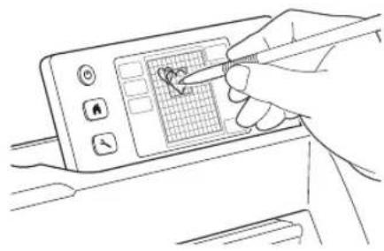
③ Touch in the pattern layout screen.

4 Touch in the layout editing screen.
- For details on the functions in the layout editing screen, see "Layout Editing Functions" on page 43.

5 Select , and then touch the "OK" key.
- Two pattern selection functions are available depending on your preference. For details on selecting multiple patterns, see "Selecting Multiple Patterns" on page 39.
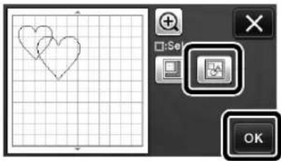
6 Touch

⑦ Check the preview, and then touch the "OK" key.

Note
- Welding pattern outlines cannot be undone. In order to recreate the original pattern arrangement, select the patterns again, and then arrange them.
The outlines of the selected patterns are welded.


Note
- This function welds the outermost outline of the patterns. When welding certain types of patterns that have inside areas cut out, the cut-out areas are not used to create the outline. Be sure that the welded patterns in the preview area meet your wishes before completing the procedure.
- Welding built-in characters

- Welding character images created by scanning

Auto Layout Functions
The auto layout function is useful when you do not wish to waste the material attached to the mat.
Touch in the pattern layout screen (page 43) to perform the auto layout function.

Note
- Depending on the pattern and material to be cut, the patterns may not be cleanly cut if their spacing is too small. In that case, rearrange the patterns to slightly separate them.
- The spacing between arranged patterns can be specified in the settings screen (see "Pattern Interval" on page 31). Perform the auto layout function after every time you adjust the spacing between patterns so the changes are applied.
- Set the number to "3" or higher in the "Pattern Interval" setting when lightweight fabric is attached to the mat with a high tack adhesive fabric support sheet.

①Rearranging By Rotating Patterns to Any Angle
This is useful when arranging a large number of patterns in a limited space.

②Rearranging By Rotating Patterns 0° or 180°
This is useful when arranging the printed design (vertical patterns) on paper or fabric as the material for cutting/drawing or when using the vertical grain.

③Rearranging Without Rotating Patterns
This is useful when arranging the printed design on paper or fabric as the material for cutting/drawing or when using the grain.
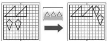
Scanning a Background Image
In this example, we will use material with a cutout in its upper-left corner as a background image.


Memo
- The background scanning function is also useful when cutting out patterns from material with a design on it. By arranging the patterns on the screen in the desired patterned area of the material, cutouts with a specific design can be created.

- This function cannot be used when an optional scanning mat is used.
- Depending on the machine model, the sizes of mats that can be used will differ. Check the "Maximum Scanning Area" under "Machine Information" on page 5 of the settings screen.
① Touch in the pattern layout screen to start the background scanning function.

The following message appears.

2 Attach the material for the background to the mat, and then press the operation panel.
For details on preparing the material and loading the mat, see "Loading the Mat" on page 27.

The mat is fed in, and the "Start/Stop" button in the operation panel lights up.
3 Press the "Start/Stop" button to start scanning.
After the material has been scanned, it appears as the background in the pattern layout screen.

①Material with a cutout displayed as background

Memo
- If it is difficult to see the arranged patterns, adjust the background contrast in the settings screen. Press in the operation panel to display the settings screen.
Background


OFF
: wakes the background image darker.
: Makes the background image lighter.
: Does not display the background image.

Touch


The layout editing screen appears.

Memo
- The pattern can also be moved by touching and dragging it in the screen.

Use the layout editing functions to move the patterns.
- For details on moving patterns, see "Layout Editing Functions" on page 43.


Memo
- The pattern can also be moved by touching the pattern(s) displayed in the layout editing screen and dragging it in the screen.

Check that the patterns in the screen do not overlap the cutouts in the background material and then touch the "OK" key.
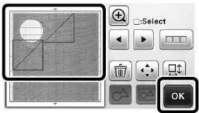

Memo
- When the scanned material is unloaded, the background is cleared.
Character Input Functions
Characters can be selected, edited, cut out and drawn as a single pattern. Select the character type from the pattern category selection screen.
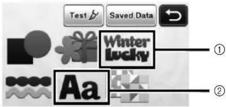
①Select decorated characters. The characters can be edited, cut out and drawn as a pattern. For details on editing, see "Pattern Editing Functions" on page 41.
②Type in the desired combination of characters.
Typing In the Word "RAINBOW"

Select the font category in the pattern category selection screen.


Touch the desired font type.

③Type in the characters.
The keyboard is in the QWERTY layout. After entering the characters, touch the "OK" key.

①Character input display
②Character keys
③Uppercase/lowercase selection key
④Space key
⑤Letter/accented character/number selection key
⑥Backspace key (deletes one character from the end of those displayed)
Memo
- If the entered characters do not fit within the cutting/drawing area, the character size is automatically reduced.
4 Adjust the settings of character size and character spacing.
Touch ☐ to adjust the character size or the space between characters. After completing the adjustment, touch the "Set" key.
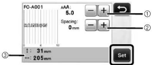
①Character size adjustment keys
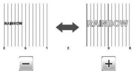
②Character spacing adjustment keys

③Size of entire character string
5 Check the character arrangement.
To cut or draw, touch the "OK" key.
To save the characters as data, touch the "Save" key. For details on saving data, see "Saving" on page 50.
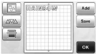
Memo
- Entered characters can only be edited as the entire character string. One character cannot be edited individually.
MEMORY FUNCTIONS
Patterns and characters arranged in the cutting/drawing area can be saved and recalled later.

Note
- USB flash drive is widely used, however some USB flash drive may not be usable with this machine. Please visit our website "http://support.brother.com" for more details.
Saving
Available in the following screen
Pattern layout screen
→Tutorial 1; Step 5 (page 34) in "Selecting and Editing the Second Pattern"
1 Touch the "Save" key to display the destination memory selection screen.

2 Touch the desired destination to start saving.
![graph LR A["①"] --> B["ScanNCut Canvas"] C["②"] --> D["USB"] E["③"] --> F["Network Connection"] B --> G["Switch"] D --> H["Switch"] F --> I["Switch"]](/content/2026/05/1011240/images/072ac156ef434dda12207ac54c427d5d02f0098b40265a13f6e4949c30689215.jpg)
①Save to the machine's memory.
When saving is finished, the following message and the name of the saved file appear.

②Save to the USB flash drive.
- In order to save data on a USB flash drive, plug the USB flash drive into the USB port (for a USB flash drive) on this machine.
When saving is finished, the following message and the name of the saved file appear.

- The name of the saved file with the extension ".fcm" is automatically assigned.
③Save to the computer.
- In order to save data to connect the computer by plugging a USB cable into this machine's USB port (for computer). For details, see "Saving Patterns in the Computer" on page 51.
④Save to ScanNCutCanvas. (Wireless network models only)
- In order to save to ScanNCutCanvas, the machine must be connected to a wireless network. This is available only after a connection has been established with ScanNCutCanvas (http://ScanNCutCanvas.Brother.com/). For details on making the connection, refer to "Wireless Network Setup Guide".
When saving is finished, the following message and the name of the project appear. For details on checking data saved in ScanNCutCanvas, refer to "Wireless Network Quick Setup Guide".

- This is a function of ScanNCut Online. For details, refer to "Overview of "ScanNCut Online" for Data Transfer via a Wireless Network" on page 11.
- If in the pattern category selection screen is blue, the machine is connected to a wireless network.

Note
- While data is being saved, do not remove the USB flash drive or disconnect the USB cable.
3 Touch the "OK" key to finish saving the data.
Saving Patterns in the Computer
■Connecting Your Machine to the Computer
- Compatible models: IBM PC with a USB port as standard equipment IBM PC-compatible computer equipped with a USB port as standard equipment
- Compatible operating systems: Microsoft Windows Vista, Windows 7, Windows 8/Windows 8.1, Windows 10
■USB cable (Sold separately)
- We recommend using a USB 2.0 cable (Type A/B) that is no longer than 2 meters (6 feet).
■Saving Patterns in the Computer
Using the USB cable, the machine can be connected to your computer, and the patterns can be temporarily retrieved from and saved in the "Removable Disk" folder in your computer. The saved patterns are deleted when the cutting machine is turned OFF.
1 Plug the USB cable connector into the corresponding USB ports for the computer and for the machine.
2 Turn on your computer and select "Computer (My computer)".

①USB port for computer ②USB cable connector The "Removable Disk" icon will appear in "Computer (My computer)" on the computer.

Note
- The connectors on the USB cable can only be inserted into a port in one direction. If it is difficult to insert the connector, do not insert it with force. Check the orientation of the connector.
3 Touch the "Save" key to display the destination memory selection screen.
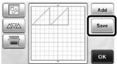
4 Touch

to return to the o
* Touch to return to the original screen without saving.

When saving is finished, the following message and the name of the saved file appear.
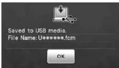
- The name of the saved file with the extension ".fcm" is automatically assigned.
The pattern will be temporarily saved to "Removable Disk" under "Computer (My computer)".
5 Select the pattern's .fcm file in "Removable Disk" and copy the file to the computer.

Recall from ScanNCutCanvas (Wireless network models only)
Using a wireless network, patterns can easily be recalled from ScanNCutCanvas (ScanNCut transfer function). This is a function of ScanNCut Online. For details, refer to "Overview of "ScanNCut Online" for Data Transfer via a Wireless Network" on page 11.
1 Connect to a wireless network and register with ScanNCutCanvas (http://ScanNCutCanvas.Brother.com/) for your machine.
- For details, refer to "Wireless Network Setup Guide".
2 Use ScanNCutCanvas to transfer the pattern to be sent to the cutting machine.
- For details, refer to "Wireless Network Quick Setup Guide".
3 Touch to recall the pattern.

- If in the pattern category selection screen is blue, the machine is connected to a wireless network.
Simply pressing places the patterns in the pattern layout screen.

Recalling

Note
- For details on the file formats that can be imported into the cutting machine from a USB flash driver or computer, see "Importing Designs" on page 54.
① Touch the "Saved Data" key to display the destination memory selection screen.

2 Touch the desired destination, and then select the desired pattern.
![graph LR A["①"] --> B["打印机"] B --> C["USB"] C --> D["③"] D --> E["电脑图标"]](/content/2026/05/1011240/images/c4a261e5bf3fd6db72d438d4f4d08f9120d0d65367164573b696530dcd4437eb.jpg)
①Recall from the machine's memory.
▶ Touch the pattern to be recalled and display a preview of the pattern layout.
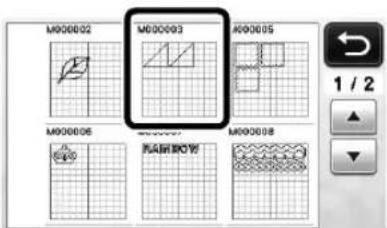
②Recall from a USB flash drive.
- To recall data from a USB flash drive, plug the USB flash drive into the USB port (for a USB flash drive) on this machine.
- If there are folders on the USB flash drive, touch a folder to display the list of patterns that it contains.
- If there are many folders or patterns, touch the arrows keys in the screen to scroll up or down.

▶ Touch the pattern to be recalled and display a preview of the pattern layout.
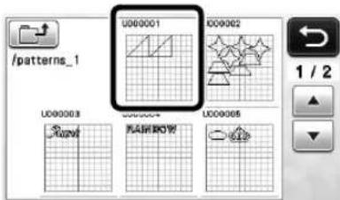
③Recall from the computer.
▶ Touch the pattern to be recalled and display a preview of the pattern layout. For details, see "Recalling from the Computer" on page 53.

Note
- If the name of the data file/folder cannot be identified, for example, when the name contains special characters, the file/folder is not displayed. If this occurs, change the name of the file/folder. We recommend using the 26 letters of the alphabet (uppercase and lowercase), the numbers 0 through 9, “-” and “.”
3 Check the preview of the pattern layout in the screen, and then touch the "OK" key.
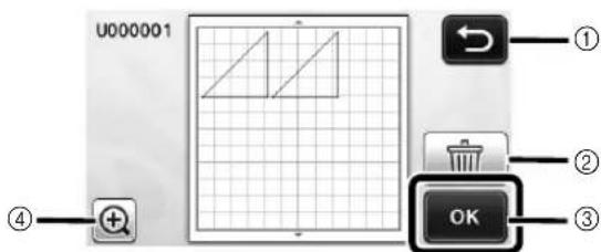
①Touch to return to the list of patterns at the destination.
②Touch to delete the data for the displayed pattern layout.
③Touch to recall the pattern layout data.
④Touch to display the patterns in zoom mode.

Memo
- Even if a seam allowance has been saved with the pattern(s) (see "Cutting Around Drawings" on page 57), the "Seam Allowance" setting specified in the settings screen will have priority and will be applied. If necessary, adjust the "Seam Allowance" setting in the settings screen (see "Seam Allowance" on page 31).
Recalling from the Computer
For Computers and Operating Systems and USB cable, see "Saving Patterns in the Computer" on page 51.
1 Plug the USB cable connector into the corresponding USB ports for the computer and for the machine.
2 On the computer, open "Computer (My computer)" then go to "Removable Disk".

3 Move/copy the pattern data to "Removable Disk".
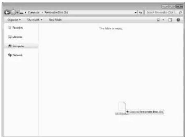
▶ Pattern data in "Removable Disk" is written to the machine.

Note
- While data is being written, do not disconnect the USB cable.
- Do not create folders within "Removable Disk". Since folders are not displayed, pattern data within folders cannot be recalled.
④ Touch the "Saved Data" key to display the destination memory selection screen.

5 Touch

The patterns in the computer are displayed on the selection screen.
6 Touch the key of the pattern you want to recall.
* Touch to return to the original screen.

⑦ Touch the "OK" key.

The Pattern layout screen is displayed.
Importing Designs
■Importable File Formats
In addition to the FCM format, files in the following formats can be imported into the machine.
- SVG (Scalable Vector Graphics: vector image format for describing two-dimensional graphics) format. “.svg” data is displayed in the pattern list screen by file name (the actual image cannot be displayed).


Memo
- The imported vector graphics will appear in the edit screen after they have been converted. This feature allows you to import only vector data. Image, text, width of the line, gradient, opacity, and any other styles or attributes of line will not be imported.
- PES/PHC format containing appliqué data (compatible models only): For details, see page 55.
Cutting an Appliqué Piece (Only on Models Compatible With Appliqué Embroidery Data Readability)
Appliqué embroidery data (.pes or .phc files) containing cutting lines can be imported into a cutting machine, which can cut out the fabric for an appliqué piece. .phc files are embroidery data from sewing machines equipped with an appliqué embroidering function, and .pes files are embroidery data created with the embroidery design software system "PE-DESIGN".

Memo
- Depending on the machine model, the availability of this function will differ. For the functions available with your machine model, check the "Brother Appliqué Embroidery Data" under "Machine Information" on page 5 of the settings screen.

Note
- For details on .pes and .phc files, contact your authorized Brother dealer or the nearest Brother authorized service center.
Preparing .pes or .phc Files
■.phc Files
Using a sewing machine that can save embroidery patterns to an external device, save an embroidery pattern with an "APPLIQUE MATERIAL" pattern to the USB flash drive or the computer. The procedure for saving the embroidery pattern to the USB flash drive or the computer differs depending on the sewing machine. Refer to the operation manual for your sewing machine.
■. pes Files
Using the embroidery design software system PE-DESIGN, save an embroidery pattern with an
"APPLIQUE MATERIAL "pattern to the USB flash drive or the computer. The procedure for saving the embroidery pattern to the USB flash drive or the computer differs depending on the version of the software. Refer to the Instruction Manual for your software.
Recalling the Pattern to the Cutting Machine and Cutting the Fabric
① Recall the embroidery pattern (.pes or .phc file) to the machine. (Refer to "Recalling" on page 52.)


Note
- .pes and .phc files can be imported into the machine via USB flash drive and USB cable direct connect. ScanNCutCanvas does not support these file formats.
"APPLIQUE MATERIAL" appears in the screen.


Memo
- If the pattern does not appear in the screen when it has been imported, even if it is a .pes or .phc file, the data cannot be cut. Check the file whether it includes "APPLIQUE MATERIAL".
2 Attach the fabric for the appliqué piece to the mat, and then cut out the pattern.
3 Refer to the operation manual for the sewing machine to complete the appliqué.
DRAWING FUNCTIONS
With a pen and pen holder, you can draw patterns on material. Using the seam allowance settings also allows you to draw patterns with seam allowances on material and then cut them out. These drawing functions can be used to create quilt pieces.
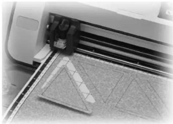
■Preparation
Prepare the following accessories for drawing. An additional purchase may be required depending on the machine model.
- Pen holder
- Erasable pen set or color pen set
- Mat appropriate for the material that will be drawn on.
- Blade and blade holder appropriate for the material that will be cut.
- Iron-on fabric appliqué contact sheet or high tack adhesive fabric support sheet appropriate for fabrics that will be cut or drawn on.
Drawing
In this example, we will draw a built-in pattern on material.
■Preparing the Pen Holder
1 Press the button at the center of the pen holder to unhook the lid and open it.
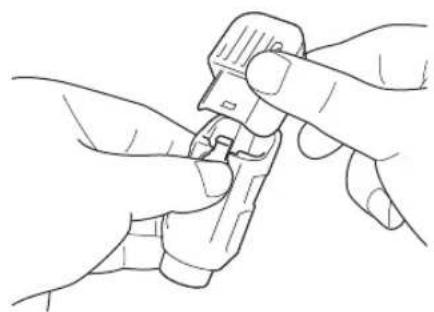
2 Remove the cap from the pen, and then insert the pen into the pen holder with the point down.
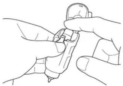
3 Close the lid of the pen holder.

Note
• After use, remove the pen from the pen holder, and then attach the cap to the pen before storing it.
■Drawing
1 Grasp the holder grip, and then install the pen holder in the carriage with its lid opening button facing against you.
- For details, see "Installing and Uninstalling the Holder" on page 26.
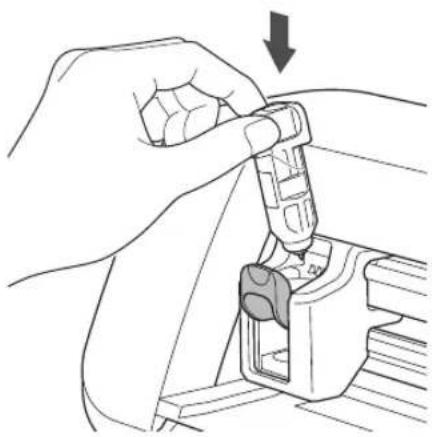
2 Select and edit the pattern.
- For details on selecting and editing patterns, see "Selecting and Editing the First Pattern" on page 33.
3 Load the mat with the material for drawing (cutting) attached.
- Lightly insert the mat into the feed slot, and press

in the operation panel.
- For details on inserting the mat, see "Loading the Mat" on page 27.
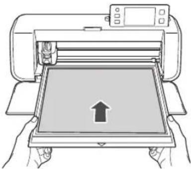
4 Select "Draw" in the draw/cut selection screen.

The drawing line (blue) appears.
5 Adjust the drawing speed and pressure.
Before drawing the pattern, adjust the drawing speed and pressure. These adjustments can be made from the settings screen. Press in the operation panel.
▶ Touch + or to change the settings.
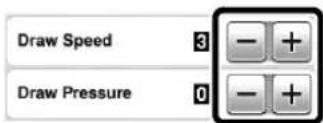

Note
- If the drawing pressure is too high, the pen tip may be damaged. Adjust it to an appropriate setting.

Memo
- Adjustments to the drawing pressure will affect the finished product. Use the same material that the pattern will be drawn on to make the adjustments.
6 Press the "Start/Stop" button in the operation panel to start drawing.

Note
• After use, remove the pen from the pen holder, and then attach the cap to the pen before storing it.
Cutting Around Drawings
In this example, we will specify a seam allowance for a built-in pattern and draw the pattern, then cut an outline around it.
■Specifying the Seam Allowance
① Touch the pattern to be drawn.
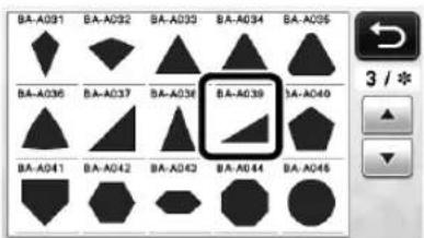
② Adjust the seam allowance.
Specify the seam allowance, which is the distance from the pattern outline to the cutting line around the pattern, in the settings screen. Press the operation panel to display the settings screen.


①Seam allowance line
②Pattern outline (stitching line)
③Seam allowance
▶ Touch the "OK" key to finish specifying the setting and return to the pattern editing screen.
③ Apply the seam allowance.
Touch to apply the seam allowance. If appears in gray, the seam allowance cannot be applied.


Memo
- Depending on the pattern, the seam allowance may be applied as a default. Check the setting.
The pattern in the preview appears with a drawing line (blue) and a cutting line (black).
4 Touch the "Set" key to finish editing the pattern.


Memo
- To draw the seam allowance on the wrong side of the fabric, flip the pattern.
Image of Pattern Piece to be Created

①Right side of fabric
②Wrong side of fabric
③Drawing line (stitching line)
④Seam allowance line
After attaching to the mat the fabric with the wrong side facing up, load the mat into the machine, flip the pattern, and then draw it and cut it out.
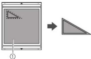
①Wrong side of fabric
5 Check the pattern arrangement, and then touch the "OK" key.
When using fabric, the patterns may not be cleanly cut if they are arranged near the edge of the fabric. In this case, move patterns so they are at least 10 mm from the fabric edge (the edge of the cutting/drawing area in the screen).
• To re-edit the pattern arrangement after checking it,
touch . For details, see "Pattern Layout Screen" on page 43.
- Select the "Cut Area" setting appropriate for the mat being used. (See page 30.)

The draw/cut selection screen appears.
■Loading the Material
Load the mat with the material for cutting (drawing) attached.
When drawing the seam allowance on the wrong side of the fabric, attach the material to the mat with its wrong side facing up.
- For details on attaching material to the mat, see "Mat and Material Combinations" on page 16.
- Lightly insert the mat into the feed slot, and press

in the operation panel.
- For details on inserting the mat, see "Loading the Mat" on page 27.
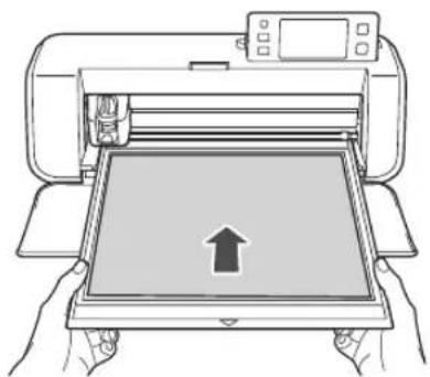
Drawing
① Touch the "Draw" key.

A preview of the line to be drawn appears.
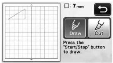
The "Start/Stop" button in the operation panel lights up.
2 Adjust the pen pressure.
For details on adjusting the drawing pressure, see step
⑤ (page 57) in "Drawing".
3 Press the "Start/Stop" button to start drawing.

When drawing is finished, the message appears in the screen. After you touch the "OK" key, the draw/cut selection screen appears.
• To perform trial drawing operations to adjust the drawing pressure, repeat steps ① through ③ in this section.
- To cut around the drawn patterns, keep the mat inserted into the slot without pressing and continue with the following cutting procedure.
Cutting
① Touch the "Cut" key.
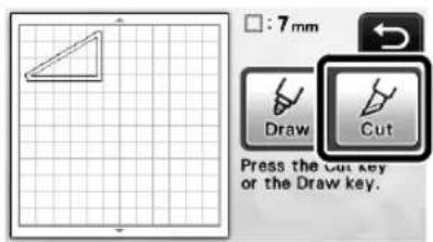
▶ A preview of the line to be cut appears.

The "Start/Stop" button in the operation panel lights up.
2 Remove the pen holder, and then install the blade holder.


Note
• After use, remove the pen from the pen holder, and then attach the cap to the pen before storing it.
CAUTION
- Please remove protective cap from blade holder before placing it into the machine carriage.
- Do not allow infants/children to put the protective caps in their mouths.
③ Press the "Start/Stop" button to start cutting.

When cutting is finished, the draw/cut selection screen appears.
4 Press in the operation panel to feed out the mat.
5 Peel the patterns off the mat.
- For details, see "Unloading the Mat" on page 28.

Chapter 4 SCANNING FUNCTIONS
SCANNING FOR CUTTING (Direct Cut)
A printed image (paper/sticker), stamped paper or an original hand-drawn illustration can be scanned and its outline can be cut out or drawn. This is useful for scanning images for paper crafts, then cutting them out.
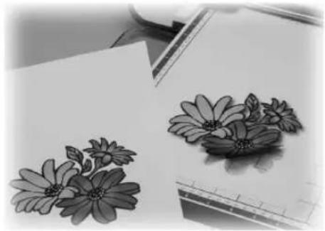
Tutorial 3 - Scanning and Cutting
In this tutorial, we will scan an illustration drawn on paper, then cut around it.

■Preparation
1 Prepare the original.

When using the "Direct Cut" mode, use originals like those described below.
- Patterns that are clearly drawn, with no gradation, fading or blurriness
• Not using an extremely intricate design


2Press to turn on the machine.
- For details, see "Turning On/Off the Machine" on page 15.
3 Install the cutting blade holder into the carriage of the machine.
- For details, see "Installing and Uninstalling the Holder" on page 26.
Scanning
Depending on the color of the illustration, it can be scanned in grayscale or color recognition mode.
① Touch the "Scan" key in the home screen to select the scanning mode.
2 Select "Direct Cut" in the scanning mode selection screen.

A message appears.
3 Select the scanning mode according to the material to be scanned.
- First, test with grayscale recognition mode. If the desired cutting data is not created, test with color recognition mode.


①Grayscale recognition mode
The cutting data is created after the illustration is converted to grayscale.
Scanning in grayscale recognition mode is most appropriate for illustrations with clear outlines or distinct brightness differences. Processing is faster with this mode compared with the color recognition mode.
If there are adjacent objects of the same color after an illustration has been converted to grayscale, select the color recognition mode.
Examples of illustrations appropriate for grayscale recognition mode:
| Example Result | ||
| Outlines that are clear |  |  |
| Distinct difference in brightness between background and illustration |  | |

Memo
- The edges of illustrations in a color of the same brightness as their background, as shown below, cannot be detected. In this case, use the color recognition mode.
①Background and illustration in colors with the same brightness.
②Color recognition mode
The cutting data is created without converting the illustration to grayscale. Creating data in this mode may take longer, depending on the pattern.
* The default scanning recognition setting is the grayscale recognition mode.
Examples of illustrations appropriate for color recognition mode:
| Example Result | ||
| Illustrations that are the same light color as the background |  |  |
| Illustrations that are the same dark color as the background |  | |
④ Attach the original that will be scanned to the mat.


Memo
- In "Direct Cut" mode, the scanning mat cannot be used.
- Depending on the machine model, the sizes of mats that can be used will differ. Check the "Maximum Scanning Area" under "Machine Information" on page 5 of the settings screen.
- Before attaching the material to the mat, use a corner of the adhesive side of the mat to test attaching it.
5 While holding the mat level and lightly inserting it under the feed rollers on the left and right sides of the feed slot, press the operation panel.
- For details, see "Loading the Mat" on page 27.
The "Start/Stop" button in the operation panel lights up.
6 Press the "Start/Stop" button to start scanning.
■Creating Cutting Data
The procedure for creating cutting data differs depending on the mode.
Grayscale recognition mode
① Check the scanned image, and then touch the "OK" key.
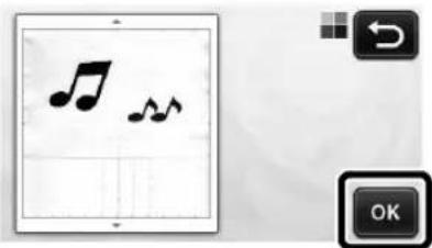
2 In the image trim screen, use the touch pen to drag to trim the image to the size to be imported.
If cutting lines are created, the outline of the scanned illustration will be black.

- Touch to change the minimum object size that will be detected and the conversion threshold. For details, see "Adjusting Image Detection Levels" on page 72.
- Touch or to edit the imported cutting data. For details, see "Advanced Cutting Functions for "Direct Cut" on page 64.
3 Touch the "OK" key to confirm the trimmed area.

▶ Only the cutting lines appear.

4 Press the "Start/Stop" button to start cutting.
- For details on unloading the mat after cutting, follow the procedure under "Unloading the Mat" on page 28.
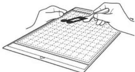
☐ Color recognition mode
In the image trim screen, use the touch pen to drag to trim the image to the size to be imported.
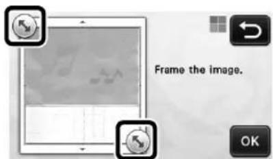
Memo
- Trimming the image to the desired size can reduce the amount of time required to convert it to cutting data.
② Touch the "OK" key to confirm the trimmed area.
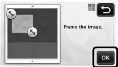
The image is converted to cutting data.
③ Check the imported image in the image editing screen.
The created cutting data appears as black lines.
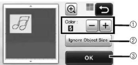
①If the cutting lines were not correctly detected, change the number of colors to be detected. If a color that appears as a single color is detected as separate colors, reduce the number of colors. If adjacent colors with a similar brightness are detected as a single color, increase the number of colors.
![graph TD A["Original Leaf Symbol"] --> B["+"] B --> C["Downward Arrow"] C --> D["Left Arrow"] D --> E["-"] E --> F["Downward Arrow"] F --> G["Right Arrow"] G --> H["Downward Arrow"] H --> I["-"]](/content/2026/05/1011240/images/dd53517312ff898ac0f3813caf1c07a85f9b948a1877367ff7fbe707ad47e102.jpg)
② Small unnecessary patterns (dotted lines, etc.) can be excluded from cutting data. For details, see "Specifying "Ignore Object Size" on page 72.
③Touch the "OK" key to apply the settings. When the number of colors is changed, the "OK" key changes to the "Preview" key. After changing the number of colors, touch the "Preview" key to check the results.

Memo
- When making a stamp, for example, the image may not be converted to cutting data if it contains a gradation or areas that are only partially filled with a color.
④ Touch the "OK" key.

- Touch or to edit the imported cutting data. For details, see "Advanced Cutting Functions for "Direct Cut" on page 64.
▶ Only the cutting lines appear.
5 Touch the "Cut" key.
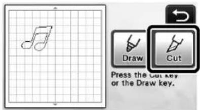
The "Cut" key is highlighted, and the "Start/Stop" button in the operation panel lights up.
6 Press the "Start/Stop" button to start cutting.
- For details on unloading the mat after cutting, follow the procedure under "Unloading the Mat" on page 28.

Advanced Cutting Functions for "Direct Cut"
■Outline Distance
Use this function to cut while adding a margin around patterns. Specify the distance from the cutting line to the outline of the scanned image.

①Pattern outline
②Cutting line
③Outline distance
Available in the following screen
| Image trim screen | →Tutorial 3; Step 3 (page 63) or Step 4 (page 64) in “Creating Cutting Data” |

Touch

- With grayscale recognition mode
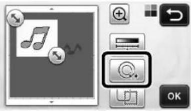
- With color recognition mode

The setting screen appears.

Touch

to char

the setting.

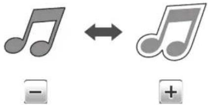

Outlining and Framing
Any shape can be specified as the cutting line for the scanned image.
Available in the following screen
Image trim screen
→Tutorial 3; Step ③ (page 63)
or Step 4 (page 64) in
"Creating Cutting Data"

Touch

- With grayscale recognition mode
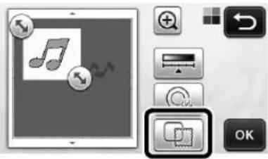
- With color recognition mode
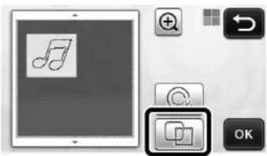
The settings screen appears.

Select the shape of the cutting line.
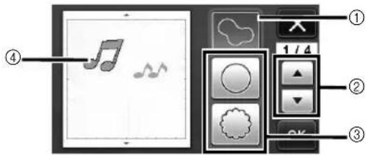
①Outlining
Touch this key to create a cutting line that follows the outline of the scanned image.
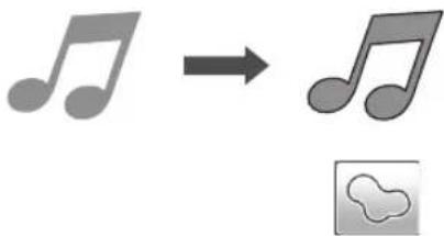

Frame Shape Scroll Keys
Touch to scroll up or down through the list of frames.
③Framing
Touch the key for the desired frame to add it to the scanned image and create a cutting line that follows its shape.
- If there are multiple images, a frame can be specified for each image.
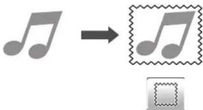
④Previewing
Display a preview of the image together with the cutting line for the selected frame.
CREATING CUTTING DATA (Scan to Cut Data)
A printed pattern or image or an original hand-drawn illustration can be scanned, converted to cutting lines for cutting/drawing with this machine, then saved as data.

Tutorial 4- Creating Cutting Data
In this tutorial, we will save an illustration drawn on paper as cutting data.

■Preparing the material
When using the "Scan to Cut Data" mode, use originals like those described below.
- Patterns that are clearly drawn, with no gradation, fading or blurriness
• Not using an extremely intricate design





■Scanning
① Touch the "Scan" key in the home screen to select the scanning mode.

2 Select "Scan to Cut Data" in the scanning mode selection screen.

A message appears.
3 Touch ,select the scanning mode, and then touch the "OK" key.
- First, test with grayscale recognition mode. If the desired cutting data is not created, test with color recognition mode.

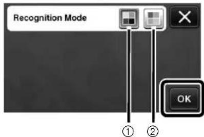
①Grayscale recognition mode
The cutting data is created after the illustration is converted to grayscale. Scanning in grayscale recognition mode is most appropriate for illustrations with clear outlines or distinct brightness differences. Processing is faster with this mode compared with the color recognition mode.
If there are adjacent objects of the same color after an illustration has been converted to grayscale, select the color recognition mode.
②Color recognition mode
The cutting data is created without converting the illustration to grayscale.
Creating data in this mode may take some time.
* The default color recognition setting is the grayscale recognition mode.
Examples of illustrations appropriate for recognition mode:
| Example | Recommended recognition mode | |
| Outlines that are clear |  | Grayscale recognition mode |
 | ||
| • Distinct difference in brightness between background and illustration• Different brightness of adjacent colors |  | |
| • Similar brightness of adjacent colors |  | Color recognition mode |

Memo
- The edges of adjacent colors with the same brightness, as shown below, cannot be detected. In this case, use the color recognition mode.


①“a” and “b” as well as “c” and “d” have the same brightness.
4 Attach the original to the mat, and then load the mat into the feed slot.
- Lightly insert the mat into the feed slot, and press in

the operation panel.
- For details on loading the mat, see "Loading the Mat" on page 27.

Memo
- Depending on the machine model, the sizes of mats that can be used will differ. Check the "Maximum Scanning Area" under "Machine Information" on page 5 of the settings screen.
5 Press the "Start/Stop" button to start scanning.
When scanning is finished, the scanned image appears in the screen.
■Creating Cutting Data
The procedure for creating cutting data differs depending on the mode.
□ Grayscale recognition mode
1 Select the cutting line type in the image editing screen.
The image shape is detected and cutting lines are created based on one of three standards. For this example, touch to create cutting lines using region detection.
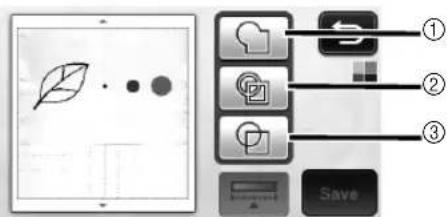
①Outline detection
If you wish to cut/draw along the outline of an image, select this option to convert the outline of the image to a cutting line. This is useful for saving as data an illustration drawn for an appliqué.
②Region detection
Select this option to detect the colored portions of an image as regions and create a cutting line around each region. Cutouts can be created using thick hand-drawn lines, such as borderlines of images or text illustrations. This option allows you to use not only cut-out patterns but the material from which portions are cut out, such as lace.
③Line detection (Grayscale recognition mode only)
Select this option to detect the center of lines and convert them to a cutting line. This is useful for detecting patterns consisting of multiple pieces and creating cutting lines for each piece.

Memo
- Lines thicker than 1.5 mm will not be detected as lines.
Difference in cutting lines depending on detection standard
Example 1
| 1 Outline detection | 2 Region detection | 3 Line detection | |
| Original |  | ||
| Cutting lines |  | 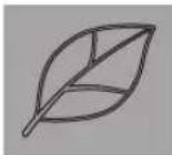 |  |
| Finished project after cutting |  |  |  |
Example 2
| 1 Outline detection | 2 Region detection | 3 Line detection | |
| Original |  | ||
| Cutting lines |  |  | Does not apply since there are no outlines for each color in the original. |
| Finished project after cutting |  |  | |
2 Use the touch pen to touch and drag it around the screen to trim the cutting lines to be saved as data, and then touch the "Save" key.

- Touch to change the minimum object size that will be detected and the conversion threshold. For details, see "Adjusting Image Detection Levels" on page 72.
☐ Color recognition mode
In the image trim screen, use the touch pen to drag to trim the image to the size to be imported.


Memo
- Trimming the image to the desired size can reduce the amount of time required to convert it to cutting data.
② Touch the "OK" key to confirm the trimmed area.

3 Select the detection standard in the image editing screen.
The image shape is detected and cutting lines are created based on one of two standards. For this
example, touch to create cutting lines using region detection.
For details on the detection standards, see step 1 in "Grayscale recognition mode".
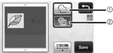
①Outline detection
②Region detection
Difference in cutting lines depending on detection standard
| 1 Outline detection 2 Region detection | ||
| Original |  | |
| Cutting lines | 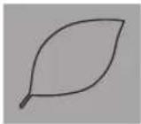 |  |
| Finished project after cutting |  |  |
- Touch to change the number of colors and the minimum object size that will be detected.
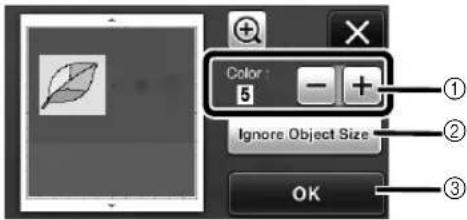
①If the cutting lines were not correctly detected, change the number of colors to be detected. If a color that appears as a single color is detected as separate colors, reduce the number of colors. If adjacent colors with a similar brightness are detected as a single color, increase the number of colors.
![graph TD A[" "] --> B["+"] B --> C["-"] D[" "] --> E["+"] E --> F["-"] G[" "] --> H["+"] H --> I["-"]](/content/2026/05/1011240/images/cb6ea68fbbdc9cbbb1e97fad988a24f52a2f31f97e606c524356c5e746c60969.jpg)
② Small unnecessary patterns (dotted lines, etc.) can be excluded from cutting data. For details, see "Specifying "Ignore Object Size" on page 72.
③Touch the "OK" key to apply the settings. When the number of colors is changed, the "OK" key changes to the "Preview" key. After changing the number of colors, touch the "Preview" key to check the results.
Memo
- When making a stamp, for example, the image may not be converted to cutting data if it contains a gradation or areas that are only partially filled with a color.
Saving Data
1 Select the destination where the data will be saved.
Select the desired location. For this example, select the machine.
![graph LR A["①"] --> B["ScanNCut Canvas"] C["②"] --> D["USB"] E["③"] --> F["PC"]](/content/2026/05/1011240/images/dbb3737b07f914b85f57f1d473f2f5cfad85648f7e26c2a852c163248af259ca.jpg)
①Machine
②USB flash drive
③Computer
④ScanNCutCanvas (Wireless network models only. This is available only after a connection has been established with ScanNCutCanvas. For details, refer to "Wireless Network Setup Guide".)
▶ Touching a key starts saving the data. When the data has been saved, the following message appears.

2 Touch the "OK" key to finish saving the data.
3 Press in the operation panel to feed out the mat, and then peel off the original from the mat.
■Recalling Cutting Data
Saved cutting data can be recalled for cutting.
① Attach the material for cutting to the mat, and then load the mat.
- For details on attaching the material, see "Mat and Material Combinations" on page 16. - For details on loading the mat, see "Loading the Mat" on page 27.
2 Recall the saved cutting data.
- For details on recalling data, follow the procedure under "Recalling" on page 52.
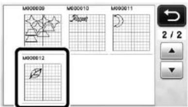
▶ A preview of the pattern layout appears.
3 Edit the cutting data as necessary, and then cut or draw.
For details on finishing cutting, follow the procedures under "Loading the Mat" (page 27) and "Cutting" (page 28).
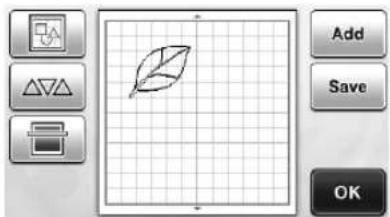


Memo
- Small spots and unwanted lines created during scanning can be deleted after a scanned image is converted to cutting data.
After recalling the cutting data into the pattern layout screen, use the editing functions for selecting the spots to delete. For details on the function, see "Specifying the Selection Area" on page 40.

①Touch for selecting multiple patterns in the specified area.
②Unwanted spots and lines
▶ Specify the area of the unwanted spots, and then touch the "OK" key.

▶ Touch to delete all of the selected spots.

Adjusting Image Detection Levels
The output levels of the scanned image data can be adjusted.
Available in the following screen
| Image editing screen | →Tutorial 4; Step 1 (page 68) or Step 3 (page 69) in “Creating Cutting Data” |
■Specifying "Ignore Object Size"
Small unnecessary patterns (dotted lines, etc.) can be excluded from cutting data. In the following example, we will scan three images of different sizes (4 mm, 40 mm, 100 mm). This example describes the procedure using the grayscale recognition mode screen of the "Scan to Cut Data" mode.
1 Select one of the detection options, and then touch to display the function selection screen.

2 Touch "Ignore Object Size" to display the setting screen.

③ Specify an object size smaller than which is not to be converted to cutting lines.

①Magnifying
②Size Adjustment Keys
③Locking/Unlocking the Aspect Ratio
![graph LR A["1"] --> B["2"] C["•"] --> D["•"] E["•"] --> F["•"] G["•"] --> H["•"] I["•"] --> J["•"] K["•"] --> L["•"] M["•"] --> N["•"] O["•"] --> P["•"] Q["•"] --> R["•"] S["•"] --> T["•"] U["•"] --> V["•"] W["•"] --> X["•"] Y["•"] --> Z["•"] AA["−"] --> AB["+"]](/content/2026/05/1011240/images/cb9a3ea61e5da8f6752e2ac12f15b5b1d57e91fc498abf66f251d1ad09defd1a.jpg)
①Cutting line created
② No cutting line created
▶ Touch the "OK" key to apply the settings. Touch
✗ to return to the previous screen without applying the settings.
■Setting Image Detection Level (Grayscale recognition mode only)
Convert an image with a gradation or shading to a two-tone (black and white) image, and then create cutting lines for that image. The image detection level (threshold) can be specified. In the following example, we will scan three images of different tones (light, medium, dark).
① Touch in the function selection screen to display the setting screen.
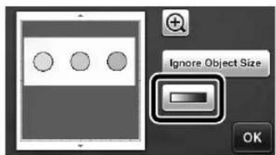
2 Specify the threshold for converting an image to a two-tone image using and.

① Cutting line created
② No cutting line created
▶ Touch the "OK" key to apply the settings. Touch
✗ to return to the previous screen without applying the settings.
SCANNING IMAGES (Scan to USB)
A pattern printed on paper or fabric, an image, a pattern template or an original hand-drawn illustration can be scanned and saved as image data on a USB flash drive. This is useful for saving the data of an original image as backup before cutting.
Notes on Scanning
■Scanning Specifications
• Scanning format: Color
- Saved file format: jpg
■Material That Can be Scanned
| Thickness | Max. 1.5 mm |
| Type | Paper/Fabric |
| Mat | Mat suitable for the material (See page 16.) |

Memo
- Depending on the machine model, the sizes of mats that can be used will differ. Check the "Maximum Scanning Area" under "Machine Information" on page 5 of the settings screen.
- Use the optional scanning mat to secure the paper or fabric to be scanned. The mat can be used without attaching the paper or fabric to the mat.
Tutorial 5- Scanning to USB
In this tutorial, we will save an illustration drawn on paper as JPEG data to a USB flash drive.
■Scan Settings
① Plug the USB flash drive into the USB port (for a USB flash drive) on this machine.

2 Touch the "Scan" key in the home screen to select the scanning mode.

3 Select "Scan to USB" in the scanning mode selection screen.

A message appears.
4 Touch to display the scanning settings screen.
Specify the size of the area to be scanned and the scanning resolution.

5 Touch ☐ for "Scan Size") to display the scanning size settings screen.

6 Select the size of the scanning area.
From the list, touch the key for the size of the original to be scanned. For this example, select the A4 size.

①Size selection keys
②Touch to cancel the setting and return to the previous screen.
③Touch to scroll through the list.
After the selected key is highlighted, touch the "OK" key to finish specifying settings.
- Select "Custom", and then touch the "OK" key to specify the desired scanning area. For details, see "Selecting the Area to be Saved" on page 75.
⑦ Touch (for "Scan Resolution") to display the scanning resolution settings screen.

8 Select the scanning resolution.
From the list, touch the key for the scanning resolution. For this example, select 150 dpi.
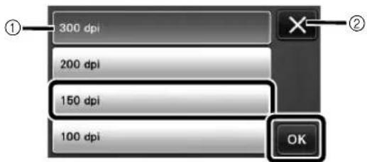
①Resolution selection keys
②Touch to cancel the setting and return to the previous screen.
After the selected key is highlighted, touch the "OK" key to finish specifying settings.
9 Check the settings, and then touch the "OK" key.
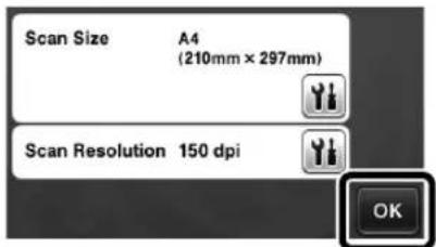
A message appears.
■Scanning and Saving
① Attach the original that will be scanned to the mat.


Note
- Place the original to be scanned so that it is in the landscape orientation.

①12" × 12" (305 mm × 305 mm)
②Letter (216 mm × 279 mm)
③A4 (210 mm × 297 mm)
④8" × 8" (203 mm × 203 mm)
⑤5" × 7" (127 mm × 178 mm)
⑥4" × 6" (102 mm × 152 mm)
⑦3.5" × 5" (89 mm × 127 mm)
2Load the mat into the feed slot.
For details on loading the mat, see "Loading the Mat" on page 27.
3 Press the "Start/Stop" button to start scanning.
The data is saved at the same time that the original is being scanned.
When scanning and saving is finished, the completion message appears.
④ Touch the "OK" key to exit "Scan to USB" mode.

5 Press in the operation panel to feed out the mat.
6 Unplug the USB flash drive from the USB port (for a USB flash drive) on this machine.
⑦ From a computer, check the saved image data.
Selecting the Area to be Saved
When saving a scanned image to a USB flash drive, the desired scanning area can be specified.
① Follow steps ① through ⑤ in "Scan Settings" of "Tutorial 5- Scanning to USB" on page 73.
2 Select "Custom", and then touch the "OK" key.
③ Using the touch pen, drag to select the scanning area, and then touch the "OK" key.

- The scanning area (white area) can also be dragged to move it.

Memo
- Load the mat with the original to be scanned attached, and then touch to display the mat in the screen. The scanning area can be selected while viewing the displayed image.
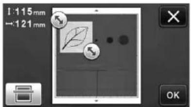
- On models compatible with 24-inch scanning, the mat size key ( ) appears. (Mat size key: With each press of the key, the mat size setting switches between 12" × 12" (305 mm × 305 mm) and 12" × 24" (305 mm × 610 mm).)
④ Continue from step ⑦ in "Scan Settings" of "Tutorial 5- Scanning to USB".
CONSUMABLES
Replacement Criteria
For the safe operation of this machine, replace the following consumables according to the replacement criteria. To purchase parts, contact the retailer who sold you this machine or the nearest authorized service center. For details on the optional accessories, see "OPTIONAL ACCESSORIES" on page 91.
Mat
- When the mat's adhesive strength decreases
- When there are many cutting traces in the mat
Cutting blade
- When the cuts in the material become rough, reducing the quality of the finished product
- When the cutting edge becomes blunt
- When the blade is chipped (If it cannot cut even though the blade extension or cutting pressure is set higher than necessary, the blade may be chipped.)
High tack adhesive fabric support sheet
- When the sheet's adhesive strength decreases
- When fabric attached becomes twisted while being cut
Scanning mat
- When the mat and cover sheet become dirty, reducing the quality of the scan image
Erasable pen
- When the ink is dry and not marking the fabric properly
- When the ink is used completely
Color pen
- When the ink is dry and not marking the paper or material properly
- When the ink is used completely
Replacing the Blade
■Removing
① Twist off the holder cap to remove it.
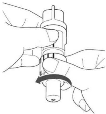
2 Stick the blade straight into the rubber area on the back of the included spatula.

①Rubber area
3 Pull up the holder to leave the blade in the rubber area.

Installing
1 Grasp the shaft of the new blade, and then insert it into the blade slot in the end of the holder.
The blade shaft is held in place by a magnet in the holder. Slowly insert the blade shaft, and then slowly release it after the shaft snaps into place against the magnet.

2 Twist on the holder cap to attach it to the holder.
Fully tighten the cap until the blade extension reaches its maximum, and then loosen the cap until the blade is no longer visible.

①Tighten the cap until the blade extension reaches its maximum.
②Loosen the cap until the blade becomes invisible from the cap end.

Note
- Loosen the holder cap until the blade tip is no longer visible. The blade extension scale on the holder applies when the blade begins to be extended from the cap end. For details on the blade extension, see "Adjusting the Blade Extension" on page 24.
CAUTION
• After removing the blade holder from the machine, be sure to retract the blade into the holder and attach the protective cap.
- Do not leave the blade extended. Otherwise, injuries may result.
- Please remove protective cap from blade holder before placing it into the machine carriage.
- Do not allow infants/children to put the protective caps in their mouths.
Cleaning
■Cleaning the Mat
Cuttings and cut edges of patterns attached to the mat may reduce the mat's adhesive strength and prevent correct operation. Periodically clean the mat. Using the included spatula, lightly scrape off any cuttings attached to the mat.

Use commercially available tweezers to remove any fabric threads attached to the mat.

Clean the dotted marks on the mat and their surrounding area with a dry cloth.


Note
- Do not use alcohol or water to clean the mat.
- When the mat is not being used, clean it, and then store it with the protective sheet affixed. If the protective sheet is not affixed, the mat's adhesive strength will decrease. At that time, do not affix the protective sheet while the mat is damp. Otherwise, the mat's adhesive strength will decrease.
- Do not fold or bend the mat to store it.
- Store the mat at room temperature and in a location not exposed to high temperatures, high humidity or direct sunlight.
- If the mat no longer has any adhesive strength, replace it with a new one. For details on optional mats, see "OPTIONAL ACCESSORIES" on page 91.
■Cleaning the Holder
If material cuttings, lint or dust accumulate in the holder, it may not operate correctly. Clean the holder after every use.
① Twist off the holder cap to remove it.
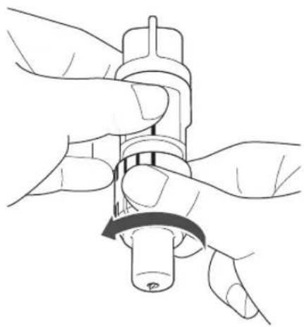
2 Using a commercially available brush, clean off cuttings, lint and dust.
Specifically clean off lint and dust around the blade. If lint and dust accumulate between the blade and holder, the blade may no longer rotate or the cutting quality may become poor.

3 Attach the holder cap to the holder.
For details on attaching the holder cap, see "Installing" on page 77.
■Cleaning Inside the Machine
If there are vertical lines or blank areas in the scanned image, lint or dust may have accumulated in the machine. The Lint may also attach to the surface of the feed rollers, preventing a mat to be loaded or unloaded correctly. Use a soft brush to clean it.
1 Turn off the machine and disconnect the power cord plug, and then disconnect the AC adapter plug from the DC power jack on the back of the machine.

2 Open the cover on the front of the machine.
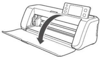
③ Remove the holder from the carriage.
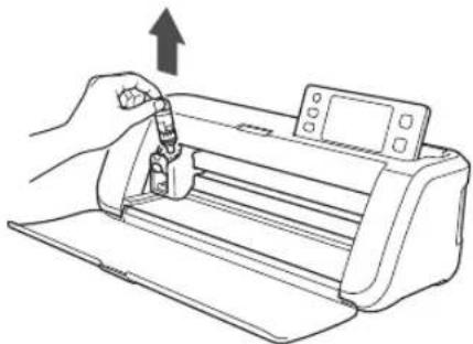
4 Use a commercially available brush to clean around the feed slot and the carriage.
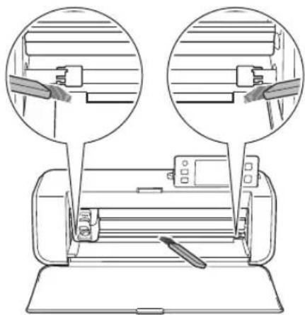
Cleaning the Scanner Glass
If there are unwanted vertical lines in the scanned image or if scanning cannot be done cleanly, the scanning area of the scanner may have become dirty. Clean the scanner glass at the bottom of the machine.
1 Turn off the machine and disconnect the power cord plug, and then disconnect the AC adapter plug from the DC power jack on the back of the machine.

2 Store away the operation panel.
First raise the panel until it is vertical, and then lower and store it away.

③ While pushing in the tab at the bottom of the machine, pull up on the cover.
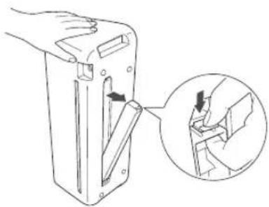
4 Dampen a soft lint-free cloth with water and firmly wring it out, and then wipe the scanner glass at the inside on the bottom of the machine.

5 Fit the tab on the cover into the notch of the installation slot, and then attach the cover to the machine.
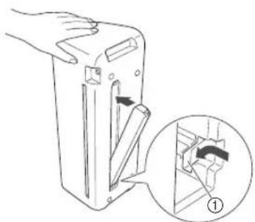
①Notch
6 After cleaning, perform a test scan.
Adjusting the Screen
If the screen does not respond correctly when you touch a key (the machine does not perform the operation or performs a different operation), follow the steps below to make the proper adjustments.
① Holding your finger on the LCD screen, turn the main power to off and back to on.

The touch panel adjustment screen is displayed.
2 Using the included touch pen, lightly touch the center of each +, in order from 1 to 5.
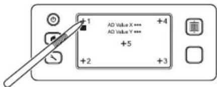
After completing the touch panel adjustment, the message "SUCCESS" appears on the screen.
③Turn the main power to off, then turn it back to on.

Note
- If you finish the screen adjustment and the screen still does not respond correctly, or if you cannot do the adjustment, contact the retailer who sold you this machine or the nearest authorized service center.
Adjusting the Scanning/Cutting Position
In "Direct Cut" mode, the cutting position can be manually adjusted if it has shifted.
For details on the "Direct Cut" mode, see "SCANNING FOR CUTTING (Direct Cut)" on page 61.
■Materials
| Paper | Thick paperColor: WhiteSize: A4 size (210 mm × 297 mm) or Letter size (216 mm × 279 mm)Thickness: 0.1 to 0.3 mm(recommended) |
| Mat | Mat suitable for the material (See page 16.) |
| Cutting blade | Standard cut blade (turquoise) |

Memo
- If the paper described above is unavailable, the paper can be replaced with copy paper. Be sure to first test attaching it to a mat suitable for the paper.
① Adjust the blade extension, and then insert the holder into the carriage.
- For details, follow the procedures under "Adjusting the Blade Extension" on page 24 and "Installing and Uninstalling the Holder" on page 26.
2 Attach the paper to the mat.
- Align the upper-left corner of the paper with the upper-left corner of the mat.
- For details on attaching the paper, follow the procedure under "Attaching the Material (Paper)" on page 18.

①Long side
②Short side
3 Touch Inside "Scanning/Cutting Position Adjustment" in the settings screen.
- This function is not available if a scanning function is being used. First quit the scanning function.

The following message appears.

- Touch the "OK" key.
4 Press to feed in the mat.
- For details, see "Loading the Mat" on page 27.

5 Press the "Start/Stop" button to start cutting.
See "Cutting" on page 28.
- Touch return to the previous screen.

▶ Position adjustment cuts are cut, and then the cuts are scanned.

- Use the cut crosses on the left and right sides to adjust the scanning position.
6 When the scan of the cut (left) appears, touch the arrow keys to align the red center of the circle with the center of the cut.

⑦ Touch the "Next" key.
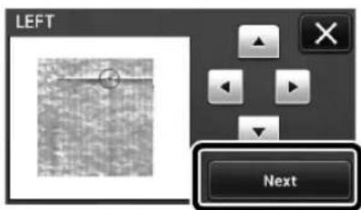
8 Adjust the right cut in the same way, and then touch the "OK" key.

9 When the following message appears, touch the "OK" key.

The adjustment is finished.

Note
- To perform the adjustment again or to return the settings to their defaults, touch the appropriate key below.

①Reset
Touch to return the settings to their defaults.
②Show manual adjustment
Manual adjustment is enabled. If the pattern has never been scanned since the machine was turned on, this key will appear in gray. When this key is available, a previous scan of the image is stored in the memory. Press this key to adjust the scanned image. When the machine is turned off, the scanned images are erased.
10 Use "Direct Cut" mode to check the adjustment results.
- For details on the "Direct Cut" mode, see "SCANNING FOR CUTTING (Direct Cut)" on page 61.
TROUBLESHOOTING
If the machine stops operating correctly, check the following possible problems before requesting service. You can solve most problems by yourself. If you need additional help, the Brother Solutions Center offers the latest FAQs and troubleshooting tips. Visit us at "http://support.brother.com". If the problem persists, contact the retailer who sold you this machine or the nearest authorized service center. For wireless network troubleshooting, refer to "Wireless Network Setup Guide".
Power Supply
| Symptom Possible Causes (or Results) Solutions Reference | |||
| The machine cannot be turned on. | The AC adapter is not correctly connected to the machine. | Check that the AC adapter is connected to the machine and that the power cord is connected to the AC adapter and electrical outlet. | page 15 |
Mat
| Symptom Possible Causes (or Results) Solutions Reference | |||
| The mat cannot be inserted. | When the mat was inserted, it was not placed under the feed rollers. | Insert the mat so that it is placed under the feed rollers on the left and right sides of the feed slot. | page 27 |
| The mat was not loaded using the “Feed” button. | Lightly insert the mat into the feed slot, and then press the “Feed” button. | page 27 | |
| The mat cannot be recognized. | The dotted marks on the part of the mat that is inserted are dirty. | Clean the dotted marks on the mat and their surrounding area. | page 78 |
| The dotted marks on the part of the mat that is inserted are hidden by material that was attached. | Attach the material while keeping it within the adhesive area of the mat. | page 18 | |
| The mat was inserted so that the side with the material attached is facing down. | Insert the mat so that the side with the material attached is facing up. | page 27 | |
| The scanner glass is dirty. | Clean the scanner glass from the bottom of the machine. | page 79 | |
| The mat is fed in at an angle. | The mat was inserted into the feed slot at an angle. | Press the “Feed” button to feed out the mat, and then re-insert it straight in. | page 27page 28 |
| The corners of the mat are deformed (bent). | Replace the mat with a new one. page 76 | ||
| The material to be cut/ drawn or original to be scanned cannot be attached to the mat. | The material extends from the adhesive area of the mat. | Attach the material while keeping it within the adhesive area of the mat. | page 18 |
| The mat’s adhesive strength has decreased. | Replace the mat with a new one. page 76 | ||
| The mat cannot be fed out. | The material to be cut/drawn or original to be scanned is jammed in the feeding mechanism in the machine. | Press the “Feed” button while the mat is being inserted to feed it out.If the mat does not feed out, turn off the machine, and then carefully pull out the mat. | page 28 |
| When the mat is inserted, the attached material peels off. | The mat is not level due to the weight of the material. | With your hands, hold the mat level when inserting it. | page 27 |
| The mat’s adhesive strength has decreased. | Replace the mat with a new one. page 76 | ||
Paper/Fabric Jam
| Symptom Possible Causes (or Results) Solutions Reference | |||
| The mat cannot be fed. | There is an obstruction around the slot at the back of the machine. | Maintain space around the slot at the back of the machine so that the mat can be fed out. | page 12 |
| The surface where the machine is installed is uneven. | Place the machine on a flat, even surface. | — | |
| Symptom | Possible Causes (or Results) | Solutions | Reference |
| The mat or the material catches on a feed roller when the mat is being inserted. | The mat's adhesive strength has decreased, or the material is not secured. | Press the “Feed” button to feed out the mat, and then replace the mat with a new one. | page 28 page 76 |
| The material extends from the adhesive area of the mat. | Press the “Feed” button to feed out the mat, and then attach the material while keeping it within the adhesive area of the mat. | page 18 page 28 | |
| The mat or the material catches on a feed roller during cutting/drawing. | - The mat's adhesive strength has decreased, or the material is not secured.- The material extends from the adhesive area of the mat. | Press the “Start/Stop” button to stop the operation. Follow the instructions on the screen, and press the “Feed” button to feed out the mat.If the mat does not feed out, turn off the machine, remove the holder, and then manually feed out the mat.After feeding out the mat, replace it with a new one or attach the material while keeping it within the adhesive area of the mat. | page 18 page 28 page 76 |
| The mat is fed in at an angle and is not fed during cutting/drawing. | |||
| The material to be cut/ drawn or original to be scanned peels off during cutting/scanning. | |||
Cutting
| Symptom | Possible Causes (or Results) | Solutions | Reference |
| The material being cut catches on the tip of the cutting blade. | Dust or lint has accumulated in the holder. | Clean the holder. page 78 | |
| The blade is worn. | Replace the blade with a new one. | page 76 | |
| The material being cut is incompatible with this machine. | Replace the material with one compatible with this machine. | page 16 | |
| The machine stopped while an operation is being performed. | For safety, the machine stops operating if the panel is touched while cutting or drawing. | Follow the instructions in the message that appears in the screen. Touch the “OK” key to move the carriage to its initial position. Load the mat and perform the operation again. | — |
| Not all of the material to be cut is cut. Some areas remain uncut. | A blade appropriate for the material being cut is not used. | Use a blade appropriate for the material being cut. | page 24 |
| The blade extension from the blade holder is too little. | Remove the holder from the carriage, and then adjust the blade extension. | page 24 | |
| If cutting is not possible even though the blade extension or cutting pressure is set higher than necessary, the blade may be chipped. | Replace the blade with a new one. page 76 | ||
| The mat's adhesive strength has decreased, or the material is not secured. | Replace the mat with a new one. page 76 | ||
| The blade is worn. | Replace the blade with a new one. | page 76 | |
| The material is incompatible with this machine. | Replace the material with one compatible with this machine. | page 16 | |
| The cutting pressure (“Cut Pressure”) is incorrect. | Adjust the setting for “Cut Pressure” in the settings screen. | page 24 page 30 | |
| Dust or lint has accumulated in the holder. | Clean the holder. page 78 | ||
| The spacing between arranged patterns is too small. | Rearrange the patterns to slightly separate them. Set the number to “3” or higher in the “Pattern Interval” setting, and then rearrange the patterns or perform the auto layout function. | page 31 page 46 | |
| Not all of the material to be cut is cut. Some areas remain uncut. | Neither a high tack adhesive fabric support sheet or iron-on fabric appliqué contact sheet is used for fabric cutting. | Attach a high tack adhesive fabric support sheet to a mat or affix an iron-on fabric appliqué contact sheet to a fabric before cutting it. | page 19page 21 |
| A fabric is not firmly attached to a mat that has a high tack adhesive fabric support sheet on its adhesive side. | Firmly attach the fabric to the mat pressing the handle of the included spatula across the surface of the fabric. | page 23 | |
| Not all of the material to be cut is cut. Some areas remain uncut. | An iron-on fabric appliqué contact sheet is not firmly attached to a fabric. | Iron the entire contact sheet to affix it firmly to the wrong side of the fabric. | page 20 |
| There are deep cuts completely through the mat. | The blade extension from the blade holder is too much. | Remove the holder from the carriage, and then adjust the blade extension. | page 24 |
| The cutting pressure (“Cut Pressure”) is incorrect. | Adjust the setting for “Cut Pressure” in the settings screen. | page 24page 30 |
Drawing
| Symptom | Possible Causes (or Results) | Solutions | Reference |
| The drawn line is thicker (thinner) than intended. | The drawing speed (“Draw Speed”) or drawing pressure (“Draw Pressure”) is incorrect. | Adjust the settings for “Draw Speed” and “Draw Pressure” in the settings screen.To draw thicker lines, increase the drawing pressure. To draw thinner lines, decrease the drawing pressure.To draw thicker lines, reduce the drawing speed. To draw thinner lines, increase the drawing speed.After adjusting the settings, perform a trial drawing operation. | page 30 |
Scanning
| Symptom | Possible Causes (or Results) | Solutions | Reference |
| Unwanted images are scanned. | The scanning area is incorrectly specified. | In “Scan to USB” mode, specify the paper size with the “Scan Size” setting. | page 73 |
| In “Direct Cut” or “Scan to Cut Data” mode, trim the image in the editing screen after scanning. | page 63 page 68 | ||
| Scanning cannot be done cleanly (there are lines in the scanned image). | The scanner glass is dirty. | Clean the scanner glass from the bottom of the machine. | page 79 |
| The original to be scanned is dirty or scratched. | In “Direct Cut” or “Scan to Cut Data” mode, remove thin lines or dirt in the image editing screen. | page 72 | |
| The lines printed on the mat are scanned. | The original is transparent so the lines printed on the mat are being scanned. | In “Direct Cut” or “Scan to Cut Data” mode, remove the lines in the image editing screen. | page 72 |
| The scanned image is red. | When the optional scanning mat is used, scanning is performed without peeling off the blue tape. | Peel off the blue tape from the optional scanning mat before scanning. | — |
ERROR MESSAGES
The following table lists some of the messages that may appear while the machine is operating as well as their corresponding solutions.
Perform the necessary operation according to the instructions in the message or the solution described here. If the problem persists, contact the retailer who sold you this machine or the nearest authorized service center.
| Error Messages Causes / Solutions | |
| A malfunction occurred. Turn the machine off, then on again. | Turn the machine off, then on again. |
| Built-in memory is corrupted.Initialize the memory. | The data on the machine's memory is corrupted. Restart the machine. |
| Cannot operate when there are too many patterns. | The message appears under the following conditions:- There are 301 or more patterns being cut in the “Direct Cut” mode.- There are 301 or more patterns being saved as cutting data in the “Scan to Cut Data” mode.Reduce the number of patterns being used.* Depending on the machine model, the maximum number of patterns will differ. Check the “Maximum Pattern Number” under “Machine Information” on page 5 of the settings screen.- There are too many cutting lines to be created after large number of small patterns are scanned.- There are too many light tone patterns to be converted to two-tone (black and white) patterns while the image detection level is being adjusted.Scan images again after reducing the number of patterns arranged in the original. |
| Cannot operate when there is no pattern. | There is no scanned image or lines for scanning.Recheck the image to be scanned, and adjust the scanning area, image detection level and “Ignore Object Size” settings.In addition, change the image drawn on the original to one more easily scanned. |
| Cannot read the data.Get the PIN code again and register to the machine. | - This message appears when you try to transfer data with a machine different than the one registered with ScanNCutCanvas.- The registration of your machine has been canceled from ScanNCutCanvas. Register the machine to be used again. |
| Cannot save the data.Get the PIN code again and register to the machine. | |
| Character string is too long for the mat. | Reduce the number of characters so that the length of the character string fits in the width of the 12-inch mat (maximum possible width 297 mm). |
| Includes a special pattern that cannot be saved to external memory.Save the pattern in the machine's memory. | Depending on the pattern, it may not be possible to save it to external memory (USB flash drive, computer or ScanNCutCanvas). |
| Initialization of the blade position failed.Turn the machine off. | Turn the machine off, then on again. |
| Initialization of the head failed.Turn the machine off. | |
| No more patterns can be added to this combination. | 301 or more patterns cannot be combined. Reduce the number of patterns.* Depending on the machine model, the maximum number of patterns will differ. Check the “Maximum Pattern Number” under “Machine Information” on page 5 of the settings screen. |
| No pattern in the effective area. | There is no pattern(s) to be cut out or drawn within the cutting area.To cut out or draw a pattern outside of the area, increase the setting for “Cut Area”, or move the pattern(s) into the area specified with “Cut Area” (page 30). |
| Not enough available memory to save the data. | Delete a file from the machine's memory or USB flash drive. |
| Not enough space on the mat.Check pattern size, space on the mat, Cut Area (setting) or Pattern Interval (setting). | Perform one of the following to arrange the patterns.- Delete a pattern already arranged in the pattern layout screen.- Resize a pattern in the arrangement.- Enlarge the setting for “Cut Area” (page 30).- Reduce the spacing between arranged patterns using the “Pattern Interval” setting. |
| Not enough space on the mat.Max: 10 (example: calculated number) | Since there are too many patterns, they cannot be arranged. Reduce the number of patterns to the maximum shown on the screen. |
| OK to retrieve and resume previous memory? | To use data from the previous operation, touch the “OK” key. (page 32) |
| Patterns cannot be unified.Invalid pair was selected. | The message appears when you are unifying patterns. Patterns with seam allowances and no seam allowances are selected as pairs. Select patterns, all of which have either seam allowances or no seam allowances. |
| Patterns cannot be welded.There are some patterns which cannot accept or no overlaps. | The message appears when you are welding patterns.- The patterns do not overlap. Rearrange them so the selected patterns overlap. Unifying the pattern, instead, can be an alternative editing method depending on your project.- A pattern that has a seam allowance is selected.Deactivate the seam allowance setting and weld the patterns.- An open shape is selected as a pattern. Only closed shapes can be welded. Unifying the pattern, instead, can be an alternative editing method depending on your project. |
| Patterns may overlap since seam allowance is set to large on the machine. | When the seam allowance setting for a pattern becomes larger than with a previous operation, the edges may overlap nearby patterns. Adjust the seam allowance setting. Otherwise, increase the spacing between patterns. |
| Replace the mat with 12 x 24 inch mat. | The 12" × 12" mat was loaded although 24-inch data was created. Load the 12" × 24" mat. |
| Scanning error occurred.Turn the machine off. | Turn the machine off, then on again, and then try performing the operation again. |
| Since the shape was larger than the mat, it was reduced in size when imported. | If the pattern in the imported SVG file is larger than the mat, the pattern will be reduced to fit the size of the mat. If necessary, in the software used to create the SVG file, edit the pattern to fit the size of the mat. |
| Some shapes could not be converted. | The imported SVG data contains data that cannot be converted, such as images or text. All other data was read as cutting line data. |
| The data cannot be deleted. | The USB flash drive being used may not be usable with this machine. If unplugging the USB flash drive and performing the operation again causes the message to appear again, replace the USB flash drive. For information about USB flash drive compatible with this machine, visit our website “http://support.brother.com”. |
| The data cannot be read. | |
| The data cannot be saved. | |
| The data could not be imported.There are too many patterns. | The message appears when an SVG file contains 301 or more patterns. In the software used to create the SVG file, reduce the number of patterns.* Depending on the machine model, the maximum number of patterns will differ. Check the “Maximum Pattern Number” under “Machine Information” on page 5 of the settings screen. |
| The data is too complicated to be imported. | SVG files containing a complicated pattern cannot be imported. In the software used to create the SVG file, simplify the pattern. |
| The mat cannot be recognized.The mat will unload. | A mat that cannot be recognized has been inserted. If a mat designed specifically for this machine is not being used, use the specially designed mat. |
| Clean the dotted marks at the edge of the mat and their surrounding area. If the mat is still not recognized, replace the mat with a new one. | |
| Clean the scanner glass from the bottom of the machine. | |
| There are no patterns that can be detected. | The imported SVG data contains data that cannot be converted, such as images or text. |
| There are some patterns which cannot add seam allowance. | The seam allowance settings cannot be specified for complex pattern shapes. Select a pattern with a simple shape.Expanding the seam allowance to 2 mm or more may help. |
| There are some patterns which cannot set cutting distance from the outline. | The cutting distance cannot be specified for complex pattern shapes. Select a pattern with a simple shape. |
| There is a pattern out of the effective area. The pattern cannot be cut or drawn.OK to continue? | There is a pattern(s) outside of the cutting area.If the pattern(s) outside of the cutting area need(s) not to be cut out or drawn, continue the operation.To cut out or draw the pattern(s) outside of the area, increase the setting for “Cut Area”, or move the pattern(s) into the area specified with “Cut Area” (page 30). |
| This data is too complicated and cannot be converted. | When you are welding or unifying patterns:Reduce the number of patterns arranged or change the patterns to ones with simple designs. |
| This mat cannot be used. | The mat is one that cannot be used with the function being performed. Replace the mat.(For example, the scanning mat was loaded while trying to cut.) |
UPDATING THE SOFTWARE
Using a USB flash drive or a computer, the machine's software can be updated. For update information, refer to details posted on the Brother Solutions Center (http://support.brother.com). If an upgrade file is posted, download the file, and then update the machine according to the following procedure.
Update Procedure Using USB Flash Drive
1 While holding down the operation panel, press to turn on the machine.
2 Plug the USB flash drive containing the upgrade file into the USB port on this machine.
The USB flash drive must not contain any data other than the upgrade file. Otherwise, the machine may stop operating correctly.


Note
- This machine is incompatible with a USB hub. Plug the USB flash drive directly into the USB port.

Touch

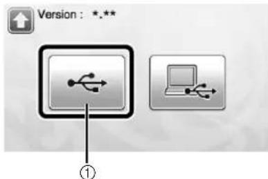
①Update using USB flash drive
4 Touch the "Update" key to start the update.

When updating is finished, the completion message appears.
5 Unplug the USB flash drive from the port.
6 Turn the machine off, then on again.
Update Procedure Using Computer
For Computers and Operating Systems and USB cable, see "Saving Patterns in the Computer" on page 51.
1 While holding down in the operation panel, press to turn on the machine.
The following screen will appear on the LCD.
2 Touch


①Update using computer
3 Plug the USB cable connector into the corresponding USB ports for the computer and for the machine.
"Removable Disk" will appear in "Computer (My computer)".
④ Copy the upgrade file to "Removable Disk".

5 Touch the "Update" key to start the update.
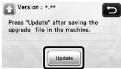
When updating is finished, the completion message appears.
6 Unplug the USB cable, and turn the machine off and on again.
OPTIONAL ACCESSORIES
The following are available as optional accessories to be purchased separately.
1.2.3.


4.5.6.


7.8.9.


-
- 12.


-
- 15.


| No. | Part Name Part Code | |
| 1 | Low tack adhesive mat 12" × 12"(305 mm × 305 mm) | CAMATLOW12 |
| 2 | Low tack adhesive mat 12" × 24"(305 mm × 610 mm) | CAMATLOW24 |
| 3 | Standard cut blade holder(turquoise) (with no blade) | CAHLP1 |
| 4 | Standard cut blade CABLDP1 | |
| 5 | Scanning mat 12" × 12"(305 mm × 305 mm) | CAMATS12 |
| 6 | Standard mat 12" × 12"(305 mm × 305 mm) | CAMATSTD12 |
| 7 | Standard mat 12" × 24"(305 mm × 610 mm) | CAMATSTD24 |
| 8 | Deep cut blade holder (purple)(with no blade) | CAHLF1 |
| 9 | Deep cut blade CABLDF1 | |
| 10 | Pen holder CAPENHL1 | |
| 11 | Color pen set CAPEN1 | |
| 12 | Erasable pen set CAPEN2 | |
| 13 | Contents USB * | |
| 14 | Iron-on fabric appliqué contactsheet (white backing) | CASTBL1 |
| 15 | High tack adhesive fabric supportsheet | CASTBL2 |
* Contact the retailer who sold you this machine or the nearest authorized service center.
INDEX
A
Advanced pattern cutting 35
Auto shutdown 30, 32
B
Background 30
Background scanning 47
Basic pattern cutting 33
Blade extension 24, 29
Buzzer sound ....31
C
Carriage 12, 26
Character input functions 48
Cleaning 78
Cut area 30,43
Cut pressure 24, 30, 35
Cut speed 30, 35
Cutting around drawings 57
Cutting blade replacement 76
Cutting line 68
D
DC power jack 12,79
Deep cut blade 24
Direct cut 6
Color recognition mode 62
Grayscale recognition mode 62
Draw pressure 30,57
Draw speed 30,57
Draw/cut selection screen 35
Drawing functions 56
E
Error messages 86
F
Feed slot 12, 27
H
High tack adhesive fabric support sheet .....17, 21
Holder lock lever 12, 26
Holder setting 26
Home screen 15,33
|
Image editing screen 64, 68, 69, 72
Image trim screen 63, 64, 69
Iron-on fabric appliqué contact sheet 17, 19
L
Language 30
Layout editing functions 43
Layout Interval 31
Low tack adhesive mat 17
M
Main power on/off 15
Main power switch 15, 33
Mat and material combinations ....16
Mat loading 27
Mat unloading 28
0
Opening screen 15,31
Operation panel 13, 14
Optional accessories 91
Outline distance 64
Outlining and framing 65
P
Parts and functions 12
Pattern category selection screen 33
Pattern editing functions 41
Pattern editing screen 33, 41
Pattern layout screen 34, 43
"Pattern" mode 10
Pattern piece editing screen ....37, 42
Pattern piece list screen 36
Pattern selection screen 33, 36
Pattern sizing screen 36
Pattern sub-category selection screen 36
Picture editing 72
R
Recalling 52
Replacement criteria 76
Required material condition (scanning) .....61, 73
S
Saving 50
"Scan" mode 10, 61
Scan to cut data 66
Color recognition mode 67
Grayscale recognition mode 66
Scan to USB 73
ScanNCutCanvas 11,50,52
Scanning/Cutting position calibration 81
Seam allowance 31, 42, 57
Selecting multiple patterns 39
Settings screen 30
Software update 89
Standard cut blade 24
Standard mat 17
Standard scale settings 24
T
Touch screen calibration 80
Trial cutting 27
Troubleshooting....83
U
Unifying (grouping multiple patterns) 44
Unit 30
USB port 12, 50, 89
W
Welding (merging the outlines of multiple patterns) ....45
Wireless network 11, 31, 50, 52
Please visit us at http://support.brother.com where you can get product support and answers to frequently asked questions (FAQs).
These machines are approved for use in the country of purchase only. Local Brother companies or their dealers will only support machines purchased in their own countries.


- TRADEMARKS
- OPEN SOURCE LICENSING REMARKS
- COPYRIGHT AND LICENSE
- INTRODUCTION
- IMPORTANT NOTICE
- IMPORTANT SAFETY INSTRUCTIONS
- SYMBOLS USED IN THIS DOCUMENT
- INSTALLATION LOCATION
- FOR SAFE OPERATION
- UNLAWFUL USE OF SCANNING EQUIPMENT
- PRECAUTIONS FOR SCANNING
- FEDERAL COMMUNICATIONS COMMISSION (FCC) DECLARATION OF CONFORMITY (FOR U.S.A. ONLY)
- IMPORTANT
- FOR USERS IN CANADA
- FOR USERS IN MEXICO
- FOR USERS IN EUROPEAN COUNTRIES
- FOR USERS IN NORWAY
- FOR USERS IN THAILAND
- CONTENTS
- 1 GETTING STARTED......12
- 2 BASIC OPERATIONS......33
- 3 ADVANCED OPERATIONS ....41
- 4 SCANNING FUNCTIONS .... 61
- 5 APPENDIX 76
- PATTERNS ("PATTERN" MODE)
- SCANNING ("SCAN" MODE)
- SELECT A PATTERN
- SCAN AN IMAGE
- OVERVIEW OF "SCANNCUT ONLINE" FOR DATA TRANSFER VIA A WIRELESS NETWORK
- PARTS AND FUNCTIONS
- UNIT DESCRIPTIONS - FRONT
- ①OPERATION PANEL
- ②CARRIAGE
- ①HOLDER
- ②HOLDER GUIDE
- ③HOLDER LOCK LEVER
- ③HANDLES
- ④FEED SLOT
- ⑤FRONT TRAY COVER
- UNIT DESCRIPTIONS - REAR
- ①USB PORT (FOR A USB FLASH DRIVE)
- ②USB PORT (FOR A COMPUTER)
- ③SLOT
- ④DC POWER JACK
- ⑤AC ADAPTER
- ⑥AC POWER CORD
- ⑦SCANNER GLASS (BOTTOM OF MACHINE)
- UNIT DESCRIPTIONS - OPERATION PANEL
- ①POWER BUTTON
- ②HOME BUTTON
- ③SETTINGS BUTTON
- ④LCD PANEL
- ⑤FEED BUTTON
- ⑥START/STOP BUTTON
- FIRST STEPS
- REMOVING THE TRANSPORT PACKING MATERIALS
- NOTE
- ADJUSTING THE ANGLE OF THE OPERATION PANEL
- USING THE TOUCH PEN AND SPATULA STAND (ON CERTAIN MODELS)
- TURNING ON/OFF THE MACHINE
- MEMO
- OPERATION OF LCD PANEL
- MAT AND MATERIAL COMBINATIONS
- ATTACHING THE MATERIAL TO THE MAT
- PAPER
- ATTACHING THE MATERIAL (PAPER)
- 2 TEST ATTACHING THE MATERIAL
- 3 ATTACH THE MATERIAL TO THE MAT'S ADHESIVE SIDE
- FABRIC (OTHER THAN FOR QUILT PIECING)
- ☐ PEELING OFF THE MATERIAL (FABRIC OTHER THAN FOR QUILT PIECING)
- ATTACHING FABRICS WITH THE DOUBLE-SIDED ADHESIVE
- ☐ NOTICE ON USE OF IRON-ON FABRIC APPLIQUÉ CONTACT SHEET
- FABRIC (FOR QUILT PIECING)
- ☐ ATTACHING THE MATERIAL (FOR QUILT PIECING)
- ① PEEL OFF THE PROTECTIVE SHEET FROM THE ADHESIVE SIDE OF THE STANDARD MAT
- 2 WITH THE GLOSSY SIDE OF THE HIGH TACK ADHESIVE FABRIC SUPPORT SHEET FACING DOWN, ATTACH IT TO THE MAT'S ADHESIVE SIDE
- ③ PEEL OFF THE BACKING FROM THE TOP OF THE SUPPORT SHEET
- 4 TEST ATTACHING THE MATERIAL
- 5 FROM ITS EDGES, ATTACH THE MATERIAL TO THE ADHESIVE SIDE OF THE MAT SO THAT THERE ARE NO WRINKLES IN THE MATERIAL
- ☐ PEELING OFF THE MATERIAL (FABRIC FOR QUILT PIECING)
- ☐ NOTICE ON USE OF HIGH TACK ADHESIVE FABRIC SUPPORT SHEET
- ADJUSTING THE BLADE EXTENSION
- CUTTING SETTINGS
- APPROPRIATE BLADE EXTENSION
- ADJUSTING THE CUTTING BLADE
- 1 REMOVE THE PROTECTIVE CAP
- CAUTION
- CHECK THE THICKNESS OF THE MATERIAL, AND THEN ADJUST THE BLADE EXTENSION. SEE "CUTTING SETTINGS" ON PAGE 24
- INSTALLING AND UNINSTALLING THE HOLDER
- ① PRESS IN THE OPERATION PANEL TO TURN ON THE MACHINE
- 2 IF THE HOLDER LOCK LEVER IS NOT RAISED, RAISE IT
- 3 GRASP THE HOLDER GRIP, AND THEN INSERT THE HOLDER INTO THE CARRIAGE
- 4 PUSH DOWN ON THE HOLDER LOCK LEVER
- 5 REVERSE THE INSTALLATION PROCEDURE TO UNINSTALL THE HOLDER
- TRIAL CUTTING
- TURNING ON THE MACHINE
- SETTING THE HOLDER
- SELECTING THE TEST PATTERN
- 1 SELECT "PATTERN" IN THE HOME SCREEN
- ② TOUCH THE "TEST" KEY IN THE PATTERN CATEGORY SELECTION SCREEN
- ③ SELECT A PATTERN IN THE PATTERN SELECTION SCREEN
- ④ TOUCH THE "SET" KEY
- 5 CHECK THE PATTERN ARRANGEMENT, AND THEN TOUCH THE "OK" KEY
- LOADING THE MAT
- 1 ATTACH THE MATERIAL THAT WILL BE CUT TO THE MAT
- 2 WHILE HOLDING THE MAT LEVEL AND LIGHTLY
- CUTTING
- UNLOADING THE MAT
- CHECKING THE TRIAL CUTTING RESULTS
- ☐ WITH AN APPROPRIATE BLADE EXTENSION
- ☐ WITH A BLADE EXTENSION THAT NEEDS TO BE ADJUSTED
- SETTINGS SCREEN
- PAGE 1
- LANGUAGE
- UNIT
- CUT AREA
- BACKGROUND
- PAGE 2
- CUT SPEED
- CUT PRESSURE
- DRAW SPEED
- DRAW PRESSURE
- PAGE 3
- AUTO SHUTDOWN
- BUZZER SOUND
- SEAM ALLOWANCE
- PATTERN INTERVAL
- PAGE 4
- OPENING SCREEN
- SCANNING/CUTTING POSITION ADJUSTMENT
- PAGE 5
- NO
- VER
- MACHINE INFORMATION
- PAGE 6 (WIRELESS NETWORK MODELS ONLY)
- NETWORK
- PAGE 7 (WIRELESS NETWORK MODELS ONLY)
- SCANNCUT ONLINE
- PATTERN CUTTING
- SELECTING AND EDITING THE FIRST PATTERN
- SELECTING AND EDITING THE SECOND PATTERN
- ① TOUCH THE "ADD" KEY IN THE PATTERN LAYOUT SCREEN
- 2 SELECT THE CATEGORY FOR THE PATTERN TO BE CUT OUT
- 3 SELECT THE SECOND PATTERN TO BE USED
- 4 EDIT THE PATTERN
- 5 CHECK THE PATTERN ARRANGEMENT
- ② ADJUST THE CUTTING SPEED AND PRESSURE
- 3 PRESS THE "START/STOP" BUTTON TO START CUTTING
- TUTORIAL 2 - CUTTING ADVANCED PATTERNS
- SELECTING AND EDITING THE FIRST PATTERN PIECE
- 2 SELECT THE CATEGORY IN THE PATTERN CATEGORY SELECTION SCREEN
- 3 SELECT THE SUB-CATEGORY IN THE PATTERN SUB-CATEGORY SELECTION SCREEN
- 4 SELECT THE PATTERN TO BE CUT OUT IN THE PATTERN SELECTION SCREEN
- 5 EDIT THE SIZE OF THE ENTIRE PATTERN USING THE PATTERN SIZING SCREEN
- 6 SELECT THE PIECE TO BE EDITED FIRST IN THE PATTERN PIECE LIST SCREEN, AND THEN TOUCH THE "OK" KEY
- ⑦ EDIT THE PATTERN PIECE USING THE PATTERN PIECE EDITING SCREEN
- 8 CHECK THE PATTERN PIECE ARRANGEMENT USING THE PATTERN LAYOUT SCREEN
- CUTTING THE FIRST PATTERN
- 1 SELECT "CUT" IN THE DRAW/CUT SELECTION SCREEN
- 2PRESS THE "START/STOP" BUTTON TO START CUTTING
- ① PRESS IN THE OPERATION PANEL TO FEED OUT THE MAT
- 2 PEEL FROM THE MAT THE PATTERN PIECE THAT WAS CUT OUT
- EDITING AND CUTTING THE SECOND PATTERN PIECE
- 1 SELECT AND EDIT THE SECOND PATTERN PIECE, AND THEN TOUCH THE "OK" KEY
- 2 FOLLOW THE PROCEDURES DESCRIBED IN "LOADING THE MAT" (PAGE 27) AND "CUTTING" (PAGE 28) TO LOAD THE MATERIAL TO BE USED FOR THE SECOND PATTERN PIECE AND CUT IT OUT
- 3 AFTER ALL PATTERN PIECES HAVE BEEN CUT OUT, TOUCH THE "FINISH" KEY
- PATTERN SELECTION
- SELECTING A SINGLE PATTERN
- SELECTING MULTIPLE PATTERNS
- SELECTING DESIRED PATTERNS
- SELECTING ALL PATTERNS
- SPECIFYING THE SELECTION AREA
- CHAPTER 3 ADVANCED OPERATIONS
- CUTTING AND EDITING FUNCTIONS
- PATTERN EDITING FUNCTIONS
- AVAILABLE IN THE FOLLOWING SCREEN
- ①SIZING (HEIGHT)
- ②SIZING (WIDTH)
- ③DUPLICATING
- ④ UNLOCKING THE ASPECT RATIO
- ⑤ROTATING
- ⑥MIRRORING
- ⑦SEAM ALLOWANCE
- ⑧PREVIEWING
- PATTERN EDITING FUNCTIONS - ADVANCED PATTERNS
- PATTERN SIZING
- EDITING THE PATTERN PIECE
- PATTERN LAYOUT SCREEN
- ①ADDING PATTERNS
- ②SAVING
- ③EDITING
- ④AUTO LAYOUT
- ⑤BACKGROUND SCANNING
- LAYOUT EDITING FUNCTIONS
- ①MAGNIFYING
- ②SELECTING PATTERNS
- ③DELETING
- ④MOVING
- ⑤EDITING INDIVIDUAL PATTERNS
- ⑥UNIFYING (GROUPING MULTIPLE PATTERNS)
- ⑦WELDING (MERGING THE OUTLINES OF MULTIPLE PATTERNS)
- UNDOING AN OPERATION
- WELDING (MERGING THE OUTLINES OF MULTIPLE PATTERNS)
- AUTO LAYOUT FUNCTIONS
- SCANNING A BACKGROUND IMAGE
- TOUCH
- USE THE LAYOUT EDITING FUNCTIONS TO MOVE THE PATTERNS
- CHECK THAT THE PATTERNS IN THE SCREEN DO NOT OVERLAP THE CUTOUTS IN THE BACKGROUND MATERIAL AND THEN TOUCH THE "OK" KEY
- CHARACTER INPUT FUNCTIONS
- TYPING IN THE WORD "RAINBOW
- ③TYPE IN THE CHARACTERS
- 4 ADJUST THE SETTINGS OF CHARACTER SIZE AND CHARACTER SPACING
- 5 CHECK THE CHARACTER ARRANGEMENT
- MEMORY FUNCTIONS
- SAVING
- SAVING PATTERNS IN THE COMPUTER
- CONNECTING YOUR MACHINE TO THE COMPUTER
- USB CABLE (SOLD SEPARATELY)
- 3 TOUCH THE "SAVE" KEY TO DISPLAY THE DESTINATION MEMORY SELECTION SCREEN
- 4 TOUCH
- 5 SELECT THE PATTERN'S .FCM FILE IN "REMOVABLE DISK" AND COPY THE FILE TO THE COMPUTER
- RECALL FROM SCANNCUTCANVAS (WIRELESS NETWORK MODELS ONLY)
- RECALLING
- RECALLING FROM THE COMPUTER
- ④ TOUCH THE "SAVED DATA" KEY TO DISPLAY THE DESTINATION MEMORY SELECTION SCREEN
- 5 TOUCH
- 6 TOUCH THE KEY OF THE PATTERN YOU WANT TO RECALL
- ⑦ TOUCH THE "OK" KEY
- IMPORTING DESIGNS
- IMPORTABLE FILE FORMATS
- CUTTING AN APPLIQUÉ PIECE (ONLY ON MODELS COMPATIBLE WITH APPLIQUÉ EMBROIDERY DATA READABILITY)
- PREPARING .PES OR .PHC FILES
- PHC FILES
- PES FILES
- RECALLING THE PATTERN TO THE CUTTING MACHINE AND CUTTING THE FABRIC
- DRAWING FUNCTIONS
- PREPARATION
- DRAWING
- PREPARING THE PEN HOLDER
- 3 LOAD THE MAT WITH THE MATERIAL FOR DRAWING (CUTTING) ATTACHED
- 4 SELECT "DRAW" IN THE DRAW/CUT SELECTION SCREEN
- 5 ADJUST THE DRAWING SPEED AND PRESSURE
- 6 PRESS THE "START/STOP" BUTTON IN THE OPERATION PANEL TO START DRAWING
- CUTTING AROUND DRAWINGS
- SPECIFYING THE SEAM ALLOWANCE
- ① TOUCH THE PATTERN TO BE DRAWN
- ② ADJUST THE SEAM ALLOWANCE
- ③ APPLY THE SEAM ALLOWANCE
- 4 TOUCH THE "SET" KEY TO FINISH EDITING THE PATTERN
- LOADING THE MATERIAL
- ① TOUCH THE "DRAW" KEY
- 2 ADJUST THE PEN PRESSURE
- 3 PRESS THE "START/STOP" BUTTON TO START DRAWING
- ① TOUCH THE "CUT" KEY
- 2 REMOVE THE PEN HOLDER, AND THEN INSTALL THE BLADE HOLDER
- CHAPTER 4 SCANNING FUNCTIONS
- SCANNING FOR CUTTING (DIRECT CUT)
- TUTORIAL 3 - SCANNING AND CUTTING
- 2PRESS TO TURN ON THE MACHINE
- 3 INSTALL THE CUTTING BLADE HOLDER INTO THE CARRIAGE OF THE MACHINE
- SCANNING
- ① TOUCH THE "SCAN" KEY IN THE HOME SCREEN TO SELECT THE SCANNING MODE
- 2 SELECT "DIRECT CUT" IN THE SCANNING MODE SELECTION SCREEN
- 3 SELECT THE SCANNING MODE ACCORDING TO THE MATERIAL TO BE SCANNED
- ①GRAYSCALE RECOGNITION MODE
- EXAMPLES OF ILLUSTRATIONS APPROPRIATE FOR GRAYSCALE RECOGNITION MODE
- ②COLOR RECOGNITION MODE
- EXAMPLES OF ILLUSTRATIONS APPROPRIATE FOR COLOR RECOGNITION MODE
- ④ ATTACH THE ORIGINAL THAT WILL BE SCANNED TO THE MAT
- ③ CHECK THE IMPORTED IMAGE IN THE IMAGE EDITING SCREEN
- ④ TOUCH THE "OK" KEY
- 5 TOUCH THE "CUT" KEY
- 6 PRESS THE "START/STOP" BUTTON TO START CUTTING
- ADVANCED CUTTING FUNCTIONS FOR "DIRECT CUT
- OUTLINE DISTANCE
- TO CHAR
- THE SETTING
- OUTLINING AND FRAMING
- SELECT THE SHAPE OF THE CUTTING LINE
- ①OUTLINING
- FRAME SHAPE SCROLL KEYS
- ③FRAMING
- ④PREVIEWING
- CREATING CUTTING DATA (SCAN TO CUT DATA)
- TUTORIAL 4- CREATING CUTTING DATA
- PREPARING THE MATERIAL
- 4 ATTACH THE ORIGINAL TO THE MAT, AND THEN LOAD THE MAT INTO THE FEED SLOT
- 5 PRESS THE "START/STOP" BUTTON TO START SCANNING
- CREATING CUTTING DATA
- GRAYSCALE RECOGNITION MODE
- 1 SELECT THE CUTTING LINE TYPE IN THE IMAGE EDITING SCREEN
- ①OUTLINE DETECTION
- ②REGION DETECTION
- ③LINE DETECTION (GRAYSCALE RECOGNITION MODE ONLY)
- DIFFERENCE IN CUTTING LINES DEPENDING ON DETECTION STANDARD
- ☐ COLOR RECOGNITION MODE
- SAVING DATA
- 1 SELECT THE DESTINATION WHERE THE DATA WILL BE SAVED
- 2 TOUCH THE "OK" KEY TO FINISH SAVING THE DATA
- 3 PRESS IN THE OPERATION PANEL TO FEED OUT THE MAT, AND THEN PEEL OFF THE ORIGINAL FROM THE MAT
- RECALLING CUTTING DATA
- ① ATTACH THE MATERIAL FOR CUTTING TO THE MAT, AND THEN LOAD THE MAT
- 2 RECALL THE SAVED CUTTING DATA
- 3 EDIT THE CUTTING DATA AS NECESSARY, AND THEN CUT OR DRAW
- ADJUSTING IMAGE DETECTION LEVELS
- SPECIFYING "IGNORE OBJECT SIZE
- SETTING IMAGE DETECTION LEVEL (GRAYSCALE RECOGNITION MODE ONLY)
- SCANNING IMAGES (SCAN TO USB)
- NOTES ON SCANNING
- SCANNING SPECIFICATIONS
- MATERIAL THAT CAN BE SCANNED
- TUTORIAL 5- SCANNING TO USB
- SCAN SETTINGS
- 6 SELECT THE SIZE OF THE SCANNING AREA
- ⑦ TOUCH (FOR "SCAN RESOLUTION") TO DISPLAY THE SCANNING RESOLUTION SETTINGS SCREEN
- 8 SELECT THE SCANNING RESOLUTION
- 9 CHECK THE SETTINGS, AND THEN TOUCH THE "OK" KEY
- SCANNING AND SAVING
- ① ATTACH THE ORIGINAL THAT WILL BE SCANNED TO THE MAT
- 2LOAD THE MAT INTO THE FEED SLOT
- 3 PRESS THE "START/STOP" BUTTON TO START SCANNING
- ④ TOUCH THE "OK" KEY TO EXIT "SCAN TO USB" MODE
- 5 PRESS IN THE OPERATION PANEL TO FEED OUT THE MAT
- 6 UNPLUG THE USB FLASH DRIVE FROM THE USB PORT (FOR A USB FLASH DRIVE) ON THIS MACHINE
- ⑦ FROM A COMPUTER, CHECK THE SAVED IMAGE DATA
- SELECTING THE AREA TO BE SAVED
- CONSUMABLES
- REPLACEMENT CRITERIA
- MAT
- CUTTING BLADE
- HIGH TACK ADHESIVE FABRIC SUPPORT SHEET
- SCANNING MAT
- ERASABLE PEN
- COLOR PEN
- REPLACING THE BLADE
- REMOVING
- INSTALLING
- CLEANING
- CLEANING THE MAT
- CLEANING THE HOLDER
- ① TWIST OFF THE HOLDER CAP TO REMOVE IT
- CLEANING INSIDE THE MACHINE
- CLEANING THE SCANNER GLASS
- 2 STORE AWAY THE OPERATION PANEL
- ③ WHILE PUSHING IN THE TAB AT THE BOTTOM OF THE MACHINE, PULL UP ON THE COVER
- 4 DAMPEN A SOFT LINT-FREE CLOTH WITH WATER AND FIRMLY WRING IT OUT, AND THEN WIPE THE SCANNER GLASS AT THE INSIDE ON THE BOTTOM OF THE MACHINE
- 5 FIT THE TAB ON THE COVER INTO THE NOTCH OF THE INSTALLATION SLOT, AND THEN ATTACH THE COVER TO THE MACHINE
- 6 AFTER CLEANING, PERFORM A TEST SCAN
- ADJUSTING THE SCREEN
- ① HOLDING YOUR FINGER ON THE LCD SCREEN, TURN THE MAIN POWER TO OFF AND BACK TO ON
- 2 USING THE INCLUDED TOUCH PEN, LIGHTLY TOUCH THE CENTER OF EACH +, IN ORDER FROM 1 TO 5
- ③TURN THE MAIN POWER TO OFF, THEN TURN IT BACK TO ON
- ADJUSTING THE SCANNING/CUTTING POSITION
- MATERIALS
- ① ADJUST THE BLADE EXTENSION, AND THEN INSERT THE HOLDER INTO THE CARRIAGE
- 2 ATTACH THE PAPER TO THE MAT
- 3 TOUCH INSIDE "SCANNING/CUTTING POSITION ADJUSTMENT" IN THE SETTINGS SCREEN
- 4 PRESS TO FEED IN THE MAT
- 5 PRESS THE "START/STOP" BUTTON TO START CUTTING
- TROUBLESHOOTING
- ERROR MESSAGES
- UPDATING THE SOFTWARE
- UPDATE PROCEDURE USING USB FLASH DRIVE
- UPDATE PROCEDURE USING COMPUTER
- ④ COPY THE UPGRADE FILE TO "REMOVABLE DISK
- 5 TOUCH THE "UPDATE" KEY TO START THE UPDATE
- 6 UNPLUG THE USB CABLE, AND TURN THE MACHINE OFF AND ON AGAIN
- OPTIONAL ACCESSORIES
- INDEX
- A
- B
- C
- D
- E
- F
- H
- L
- M
- 0
- P
- R
- S
- T
- U
- W
Brand : BROTHER
Model : ScanNCut CM650WX
Category : Paper Cutter