
VCRG24-T - Grill Vulcan - Free user manual and instructions
Find the device manual for free VCRG24-T Vulcan in PDF.


| Product type | Professional gas grill/griddle |
| Brand | Vulcan |
| Model | VCRG24-T |
| Number of burners | 2 |
| Total heat output | 50,000 BTU/h (14.6 kW) |
| Gas type | Natural gas (convertible to propane with supplied kit) |
| Supply pressure | Natural gas: 18-23 cm WC; Propane: 28-30 cm WC |
| Width | 61 cm (24 inches) |
| Depth | Approximately 91 cm (36 inches) |
| Height | Approximately 40 cm (16 inches) |
| Weight | Approximately 150 kg |
| Plate material | Steel |
| Temperature range | 200-450 °F (93-232 °C) |
| Control type | Independent mechanical thermostats per zone |
| Cooking zones | 2 zones of 30 cm each |
| Ignition | Permanent pilot with manual ignition |
| Safety | Thermocouple safety valve, automatic shut-off in case of flameout |
| Daily maintenance | Clean the plate with a wire brush or flexible spatula |
| Weekly maintenance | Complete cleaning with griddle stone, descaling and rinsing |
| Initial seasoning | Apply vegetable oil at 300-350 °F after cleaning |
| Grease drawer | Removable drawer, empty and clean regularly |
| Electrical supply | None (operates only on gas) |
| Spare parts available | Burners, pilot lights, thermostats, knobs, regulator, etc. |
| Installation | Must be performed by a qualified professional, comply with local gas codes |
| Usage | Professional (catering, intensive cooking) |
Frequently Asked Questions - VCRG24-T Vulcan
User questions about VCRG24-T Vulcan
0 question about this device. Answer the ones you know or ask your own.
Ask a new question about this device
Download the instructions for your Grill in PDF format for free! Find your manual VCRG24-T - Vulcan and take your electronic device back in hand. On this page are published all the documents necessary for the use of your device. VCRG24-T by Vulcan.
USER MANUAL VCRG24-T Vulcan
natural_image
Exterior view of a white stainless steel grater with four control knobs (no text or symbols visible)VCRG48-T
VCRG24-T
VCRG36-T
VCRG48-T
WCRG24-T
WCRG36-T
WCRG48-T
For additional information on Vulcan or to locate an authorized parts and service provider in your area, visit our website at www.vulcanequipment.com
IMPORTANT FOR YOUR SAFETY
THIS MANUAL HAS BEEN PREPARED FOR PERSONNEL QUALIFIED TO INSTALL GAS EQUIPMENT, WHO SHOULD PERFORM THE INITIAL FIELD START-UP AND ADJUSTMENTS OF THE EQUIPMENT COVERED BY THIS MANUAL.
POST IN A PROMINENT LOCATION THE INSTRUCTIONS TO BE FOLLOWED IN THE EVENT THE SMELL OF GAS IS DETECTED. THIS INFORMATION CAN BE OBTAINED FROM THE LOCAL GAS SUPPLIER.
IMPORTANT
IN THE EVENT A GAS ODOR IS DETECTED, SHUT DOWN UNITS AT MAIN SHUTOFF VALVE AND CONTACT THE LOCAL GAS COMPANY OR GAS SUPPLIER FOR SERVICE.
FOR YOUR SAFETY
DO NOT STORE OR USE GASOLINE OR OTHER FLAMMABLE VAPORS OR LIQUIDS IN THE VICINITY OF THIS OR ANY OTHER APPLIANCE.
WARNING
Improper installation,
adjustment, alteration, service or maintenance can cause property damage, injury, or death. Read the installation, operating and maintenance instructions thoroughly before installing or servicing this equipment.
IN THE EVENT OF A POWER FAILURE, DO NOT ATTEMPT TO OPERATE THIS DEVICE.
INSTALLATION, OPERATION AND CARE OF MEDIUM DUTY GAS GRIDDLES
GENERAL
Medium Duty Gas Griddles are produced with quality workmanship and materials. Proper installation, usage and maintenance of your griddle will result in many years of satisfactory performance.
Thoroughly read this entire manual and carefully follow all of the instructions provided.
| Model | Number Of Burners | BTU/hr Input Rating |
| VCRG24-T / WCRG24-T | 2 | 50,000 |
| VCRG36-T / WCRG36-T | 3 | 75,000 |
| VCRG48-T / WCRG48-T | 4 | 100,000 |
INSTALLATION
UNPACKING
This griddle was inspected before leaving the factory. The carrier assumes full responsibility for the safe delivery upon acceptance of the shipment. Check for possible shipping damage immediately after receipt.
If the griddle is found to be damaged, complete the following steps:
- Carrier must be notified within 5 business days of receipt.
- Carrier's local terminal must be notified immediately upon discovery (note time, date, and who was spoken to), and follow up and confirm with written or electronic communication.
- All original packing materials must be kept for inspection purposes.
- The griddle cannot have been moved, installed, or modified.
- Notify Vulcan Customer Service immediately at 800-814-2028.
Carefully unpack your griddle and make sure that no parts are discarded with packaging material. A pressure regulator designed to operate with the griddle has been supplied and must be installed before the griddle is placed into service (Refer to GAS PRESSURE REGULATOR INSTALLATION in this manual).
LOCATION
The installation location must be kept free and clear of combustibles. When installing, never enclose the bottom of the griddle with a raised curb or other constructions that would obstruct flow of air into or out of the griddle. Adequate clearance for air openings into the combustion chamber must be provided. Make sure there is an adequate supply of air in the room to replace air taken out by the ventilation system.
Do not permit air to blow directly at the griddle. Avoid open windows next to the griddle wherever possible. Avoid wall-type fans which create air cross-currents within the room.
This griddle is Design Certified for installation on a non-combustible counter with 4" legs, or combustible floor with 24" high stand.
INSTALLATION CLEARANCES
| COMBUSTIBLE CONSTRUCTION | NON-COMBUSTIBLE CONSTRUCTION | |
| Back: | 6" | 0" |
| Sides: | 6" | 0" |
INSTALLATION CODES AND STANDARDS
The griddle must be installed in accordance with:
In the United States of America:
-
State and local codes.
-
National Fuel Gas Code, ANSI-Z223.1/NFPA #54 (latest edition). This shall include but not be limited to: NFPA #54 Section 10.3.5.2 for Venting. Copies may be obtained from The American Gas Association Accredited Standards Committee Z223, @ 400 N. Capital St. NW, Washington, DC 20001 or the Secretary Standards Council, NFPA, 1 Batterymarch Park Quincy, MA 02169-7471
NOTE: In the Commonwealth of Massachusetts
All gas appliances vented through a ventilation hood or exhaust system equipped with a damper or with a power means of exhaust shall comply with 248 CMR.
- NFPA Standard # 96 Vapor Removal from Cooking Equipment, latest edition, available from the National Fire Protection Association, Batterymarch Park, Quincy, MA 02269.
In Canada:
- Local codes.
- CAN/CSA-B149.1 Natural Gas Installation (latest edition)
- CAN/CSA-B149.2 Propane Installation Code (latest edition), available from the Canadian Gas Association, 178 Rexdale Blvd., Etobicoke, Ontario, Canada M9W 1R3
GRIDDLES MOUNTED ON STANDS WITH CASTERS
Griddles mounted on stands with casters must use a flexible connector (not supplied) that complies with the Standard for Connectors for Movable Gas Appliances ANSI Z21.69•CSA6.16, and a quick-disconnect device that complies with Gas Fuel, ANSI Z21.3•CSA6.9. In addition, adequate means must be provided to limit movement of the appliance without depending on the connector and the quick-disconnect device (or its associated piping) to limit appliance movement. Attach the restraining device at the rear of the griddle as shown in Fig. 1.

Fig. 1
If disconnection of the restraint is necessary, turn off the gas supply before disconnecting. Reconnect the restraint prior to turning the gas supply on and returning the griddle to its installation position.
Casters are only supplied on a griddle stand. If the griddle is moved for any reason the griddle should be re-leveled (see LEVELING in this manual).
FLUE CONNECTIONS
Do not obstruct the flow of flue gases from the flue, located at the rear of the griddle. It is recommended that flue gases be ventilated to the outside of the building through a ventilation system installed by qualified personnel.
From the termination of the flue to the filters of the hood venting system, a minimum clearance of 18" must be maintained.
Information on the construction and installation of ventilating hoods may be obtained from the standard for “Vapor Removal from Cooking Equipment”, NFPA No. 96 (latest edition), available from the National Fire Protection Association, Batterymarch Park, Quincy, MA 02269.
GAS CONNECTIONS
NOTICE Gas supply connections and any pipe joint compound must be resistant to the action of propane gases.
Use a 34 " NPT gas supply line for the griddle inlet, located at the rear of the griddle. All of flexible and semi-rigid gas supply lines must comply with the applicable ANSI standard. To ensure maximum operating efficiency, this appliance must be connected with a gas supply line of solid pipe or a commercial type Flexible Connector with the net inside diameter (I.D.) as large as or larger than the gas pipe inlet on this appliance. Codes require that a gas shutoff valve must be installed in the gas line upstream of the griddle.
WARNING Prior to lighting, check all joints in the gas supply line for leaks. Use soap and water solution. Do not use an open flame.
After checking for leaks all lines receiving gas should be fully purged to remove air.
TESTING THE GAS SUPPLY SYSTEM
When the gas supply pressure exceeds 12 psig (3.45 kPa), the griddle and its individual shutoff valve must be disconnected from the gas supply piping system.
When the gas supply pressure is 12 psig (3.45 kPa) or less, the griddle should be isolated from the gas supply system by closing its individual manual shutoff valve.
GAS PRESSURE REGULATOR INSTALLATION
This griddle is supplied with a convertible gas pressure regulator preset at 4" Water Column (W.C.) for natural gas. No further adjustment should be required. Install the regulator as close to the griddle on the gas supply line as possible. Make sure that the arrow on the underside of the regulator is oriented in the direction of gas flow to the griddle (Fig. 2 on next page) and the regulator is positioned with the vent plug and conversion plug cover upright (Fig. 3 on next page).

natural_image
Close-up of a metallic mechanical component with bolt holes and internal features (no visible text or symbols)Fig. 2

natural_image
Close-up of a metallic mechanical component with bolt holes and a central hub (no visible text or symbols)Fig. 3
The supply pressure (upstream of the regulator) should be 7-9" W.C. for natural gas and 11-12" W.C. for propane gas. At no time should the griddle be connected to supply pressure greater than 12 psig (3.45 kPa) or 14" W.C.
This griddle is shipped from the factory equipped with fixed burner and pilot orifices for natural gas operation. The burner and pilot orifices required to convert the griddle to propane gas are shipped with the griddle in the shipping packaging. It is recommended that a trained gas service technician with the necessary tools, instruments and skills perform the conversion.
To convert to propane, following steps must be completed:
- Remove all natural gas burner orifices and install the provided propane burner orifices. See Fig. 4
- Remove all pilot orifices and install the provided propane pilot orifices. See Fig 4.
- Set the regulator to 10" W.C. by inverting the regulator spring plug. See Fig 5.
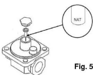
NATURAL GAS
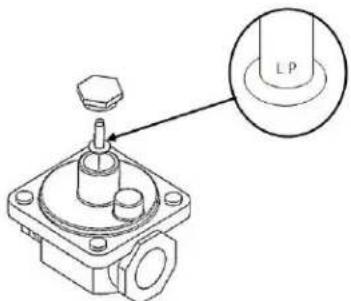
PROPANE GAS

WARNING Prior to lighting, check all joints in the gas supply line for leaks. Use soap and water solution. Do not use an open flame.
OPERATION
WARNING The griddle and its parts are hot. Use care when operating, cleaning or servicing the griddle.
BEFORE FIRST USE
Remove all packing material and protective plastic from surfaces of the unit. Before leaving the factory, the griddle plate is coated with protective coating as a rust inhibitor. Remove this film when the griddle plate is being cleaned prior to its first cooking use. Heat the griddle to 200-300°F to loosen and melt the coating, then clean the surface with a non-corrosive, grease dissolving commercial cleaner, following the manufacturer's directions. Rinse thoroughly and wipe dry with a soft clean cloth. Clean all accessories.
Season the griddle to avoid possible surface corrosion before first use, and after every cleaning. Heat griddle to a low temperature (300-350°F) and apply a small amount of cooking oil – about one ounce per square foot of surface. Use a soft lint-free cloth to spread the oil over the entire griddle surface to create a thin film. Wipe off any excess oil with a cloth. Repeat the procedure until the griddle has a slick, mirror-like finish. This will also help reduce the sticking of cooked food product.
CONTROLS
This model features a standing pilot that must be manually lit. The pilot is monitored by a thermocouple and pilot safety valve. If the pilot goes out, the safety valve will shut-off the gas supply to the pilot and main burners. There is one pilot and one safety valve for every two burners except on the 36" model. The 36" model has an odd number of main burners, therefore one of the sets of pilots and safety valves in these models will control only one main burner. The safety valve push buttons are aligned with pilot burners and the pilot sight holes are off centered 34 " to the right. The pilot burners are inset approximately 7" from the front panel. See cutaway view on page 8.
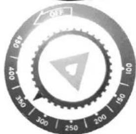
Each 12" section of the griddle is independently controlled by a mechanical snap-action thermostatic valve. The thermostats have an operating range of 200 to 450 degrees. Once pilots are lit, turning the thermostats to the desired setting is all that is required to put the unit into service.
VCRG-T / WCRG-T PILOT LIGHTING PROCEDURE
- Turn the main gas shut-off valve and all thermostats to the OFF position. Wait 5 minutes to allow any gas that may have accumulated in the burner compartment to escape.
- Turn the main gas shut-off valve ON.
- Depress and hold the safety valve button while lighting the corresponding pilot. You will have to reach under the front of the unit to light with an outside ignition source(such as a lit taper, etc.) while viewing thru the pilot sight hole.
- When the gas at the pilot has been burning for about 45 seconds, release the safety valve button. If the pilot does not remain lit, repeat the operation allowing more time before releasing the button. The amount of time necessary to hold the safety valve button will increase at the initial installation of the unit and if the main gas supply has been turned off for a long period of time. It may be necessary to adjust the pilot valve to increase gas to the pilot. See Fig. 6 on page 12.
- Repeat steps until all pilots are lit.
- If after completing steps 1-5 pilot does not light, turn off the main gas shut-off valve and contact an authorized service contractor.
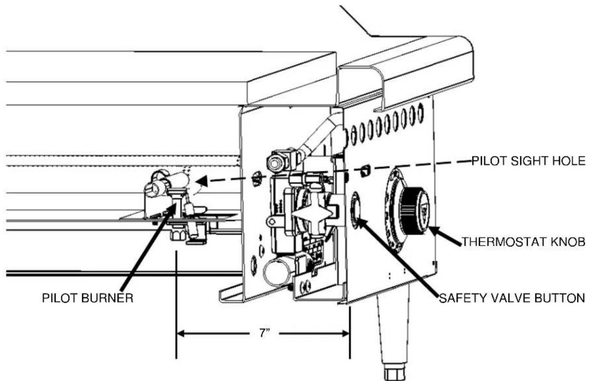
CUTAWAY VIEW
USING THE GRIDDLE
To preheat, turn the burners on about 20-25 minutes before cooking.
A uniform and systematic approach to loading the griddle will produce the most consistent product results.
The griddle plate is steel, but the surface can be scored or dented by careless use of a spatula or scraper. Be careful not to dent, scratch, or gouge the plate surface. Do not try to knock off loose food that may be on the spatula by tapping the corner or the edge of the spatula on the griddle surface.
ZONE COOKING
This griddle features a tubular U-shaped burner in each 12" section, each controlled by independent thermostats. Each 12" section is a separate cooking zone, and allows cooking a wide variety of products over a single griddle plate. The chart below is a suggested usage of zone cooking.
When zone cooking, it is suggested that you start with your lowest temperature setting at either side of the griddle, increasing the zone temperature as you move up the zone line.
These zone cooking guidelines will vary depending on product temperatures, size and shape. This guide should be adjusted to suit your product and operational cooking preference.

natural_image
Technical line drawing of four identical U-shaped arches mounted on a base plate (no text or symbols)| ZONE 1(300°F) | ZONE 2(350°F) | ZONE 3(350°F) | ZONE 4(400°F) |
| PRODUCTSausageEggs (Hard Fried)Eggs (Scrambled)Burger (Well Done)Steak (W ell Done)Chicken BreastFrozen FoodsPork Chops | PRODUCTPancakes French Toast Bacon Eggs (Sunny Side Up) Boiled Ham Steak (Medium Well)Fresh Burger (Medium Well)Small Frozen Burger (Medium Well) | PRODUCTSteak (Rare)Stir Fry VegetablesSalmonFish CakesLobsterScampi | |
CLEANING THE GRIDDLE
Empty the grease drawer as needed throughout the day and regularly clean at least once daily.
Clean the griddle regularly. A clean griddle always looks better, lasts longer and performs better. To produce evenly cooked, perfectly browned griddle products keep the griddle plate clean and free of carbonized grease. Carbonized grease on the surface hinders the transfer of heat from the griddle surface to the food, resulting in spotty browning and loss of cooking efficiency. Carbonized grease tends to cling to griddle foods, giving them a highly unsatisfactory and unappetizing appearance.
To keep the griddle clean and operating at peak efficiency, follow these procedures:
AFTER EACH USE
Clean the griddle with a wire brush or flexible spatula.
ONCE PER DAY
Thoroughly clean the griddle back splash, sides and front. Remove, empty and wash the grease drawer in the same manner as an ordinary cooking utensil.
ONCE PER WEEK
Clean the griddle surface thoroughly. Use a griddle stone, screen, or Scotch Bright™ pad on the surface as necessary. Rub with the grain of the metal while the griddle is still warm (not hot). A detergent may be used on the plate surface to help clean it, but be sure the detergent is thoroughly removed by flushing with clear water.
After removal of detergent the surface of the plate the griddle should be seasoned according to the instructions in this manual.
Clean stainless steel surfaces with a damp cloth and polish with a soft dry cloth. To remove discoloration, use a griddle cleaner.
If the griddle usage is very high, consider conducting this weekly cleaning procedure more than once per week.
ADJUSTMENTS
CALIBRATION
- Each thermostat controls a 12" zone of the griddle. Using a Surface Probe temperature measurement device, observe the temperatures at the center points of the cooking zones. These points are located by starting 6" from the side splash (left or right) and every 12" across the width of the griddle, with all points located 12" back from the front edge of the griddle plate.
NOTE: Use of infrared thermometers is not recommended. These devices are highly sensitive to surface color (clean or dirty), angle of reading and distance from the unit.
-
Set thermostats to 350^ F and allow to stabilize, allowing the burner to cycle ON and OFF at least two times.
-
Watch for burner to cycle OFF, then measure the temperature for that zone. The temperature should be 350^ F ±15^ F. If not, continue to Step 4.
4.
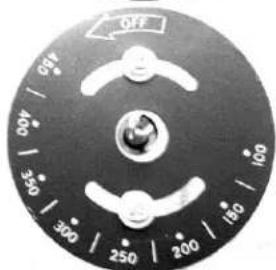
a. Carefully loosen the knob set screw. DO NOT allow the knob to turn. Carefully remove the knob from the thermostat shaft, exposing the temperature dial.
b. Loosen screws on the temperature dial and adjust to that the temperature indicated by the knob arrow matches the griddle plate temperature reading. Knob will have to be placed back on the shaft to verify adjustment.
IMPORTANT: NEVER ADJUST THE SCREW IN THE CENTER OF THE THERMOSTAT SHAFT. This will ruin the factory calibration; the thermostat will no longer operate properly and may need to be replaced.
- Once calibration is achieved, tighten the temperature dial screws and knob set screws.


Step 4a. Set knob & check Temperature. Remove knob
natural_image
Close-up of a circular mechanical dial with rotary buttons and a central knob (no text or symbols visible)Step 4b. – Adjust temperature dial & verify temperature setting
Step 5 –Replace knob & tighten screws
LEVELING
The griddle must be level (side-to-side and front-to-back) during operation to ensure proper performance. Improper leveling can result in uneven temperature distribution, cold spots, and possibly damaged components.
-
Place a level on the griddle.
-
Adjust legs by turning the bullet feet at the bottom of each leg. Using pliers or a crescent wrench, turn the feet counter-clockwise to increase height, and clockwise to decrease height until leveling is achieved. Do not extend the legs more than 1-3/4".
PILOT ADJUSTMENT
Using a flathead screwdriver, turn the slotted hex-head pilot adjustment screw clockwise to decrease the flame, and counterclockwise to increase the flame. See Fig. 6.

Fig. 6
SHUTDOWN OF GRIDDLE
- Turn thermostats to the OFF position to cut off burners.
- The pilots will remain lit and monitored by the safety valve as long as the main gas supply is on.
EXTENDED SHUTDOWN
- Shut off the main gas supply valve.
- Apply a heavy coat of vegetable oil over the griddle plate to inhibit rust.
MAINTENANCE
WARNING The griddle and its parts are hot. Use care when operating, cleaning or servicing the griddle.
LUBRICATION
There are no parts on this griddle that require lubrication.
VENT
Daily, when the griddle is cool, check the flue and clear any obstructions.
SERVICE AND PARTS INFORMATION
Contact the Service Contractor in your area to obtain service and parts information. For a complete listing of Service and Parts depots refer to or www.vulcanequipment.com.
When calling for service, the following information should be available from the appliance identification plate: Model Number, Serial Number and Gas Type.
TROUBLESHOOTING
| PROBLEM | POSSIBLE CAUSES |
| Burner does not come on when the control knob is turned on | Problem with gas valve. (Call for service)Pilot burner not lit. (Call for service)Low gas pressure. (Call for service) |
| Pilot burner will not light | Manual gas valve not turned on.Obstructed pilot orifice. (Call for service)Pilot gas turned off at pilot. Adjust pilot to allow gas flow.Low gas pressure. (Call for service) |
| Pilot burner will not stay lit | Obstructed or wrong size pilot orifice. (Call for service)Gas supply not purged of air. Depress pilot safety button until air is purged.Air blowing pilot out. (Call for service)Low gas pressure. (Call for service) |
| Fat appears to smoke excessively | Temperature set too high.Moisture in food may be turning into steam |
| Food sticks to griddle or burned around edges or contains dark specs | Temperature set too high.Griddle surface requires cleaning and/or seasoning.Surface under food not covered with enough cooking oil. |
| Food under-cooked inside | Temperature set too low.Food not cooked for long enough time. |
| Food tastes greasy or has objectionable off-flavor | Food itself may have off-flavor.Food stored improperly before cooking.Too much griddle fat used.Temperature set too low. |
| Noticeable build-up of gum on griddle | Temperature set too high.Griddle surface needs cleaning and/or seasoning.Too much griddle fat used. |
natural_image
Circular device dial with rotary buttons and a central connector (no visible text or symbols)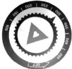
natural_image
Technical line drawing of four U-shaped pipes mounted on a platform, no text or symbols presentaliments custs gui collect.
natural_image
Close-up of a metallic mechanical component with bolts and mounting holes (no visible text or symbols)Fig.2

natural_image
Close-up of a mechanical component with no visible text or symbols- La norme NFP A n° 96 Vapor Removal from Cooking Equipment, derivative edition, disponible aurres de la National Fire Protection Association, Batterymarch Park, Quincy, MA 02269.
Batterymarch Park Quincy, MA 02169-7471
natural_image
Exterior view of a white industrial ventilation duct with three mounting holes and a recessed base (no text or symbols visible)MODELS
MANUEL D'INSTALLATION ET D'EMPLOI PLAQUE CHAUFFAENTE AU GAZ A FUNCTION MOYENNE
WOLF


- IMPORTANT FOR YOUR SAFETY
- IMPORTANT
- FOR YOUR SAFETY
- WARNING
- INSTALLATION, OPERATION AND CARE OF MEDIUM DUTY GAS GRIDDLES
- GENERAL
- INSTALLATION
- UNPACKING
- LOCATION
- INSTALLATION CODES AND STANDARDS
- GRIDDLES MOUNTED ON STANDS WITH CASTERS
- FLUE CONNECTIONS
- GAS CONNECTIONS
- TESTING THE GAS SUPPLY SYSTEM
- GAS PRESSURE REGULATOR INSTALLATION
- OPERATION
- BEFORE FIRST USE
- CONTROLS
- VCRG-T / WCRG-T PILOT LIGHTING PROCEDURE
- USING THE GRIDDLE
- ZONE COOKING
- CLEANING THE GRIDDLE
- AFTER EACH USE
- ONCE PER DAY
- ONCE PER WEEK
- ADJUSTMENTS
- CALIBRATION
- LEVELING
- PILOT ADJUSTMENT
- SHUTDOWN OF GRIDDLE
- EXTENDED SHUTDOWN
- MAINTENANCE
- LUBRICATION
- VENT
- SERVICE AND PARTS INFORMATION
- MANUEL D'INSTALLATION ET D'EMPLOI PLAQUE CHAUFFAENTE AU GAZ A FUNCTION MOYENNE
Brand : Vulcan
Model : VCRG24-T
Category : Grill