
FSGYMSTN45A - Fitness Equipment Fortis - Free user manual and instructions
Find the device manual for free FSGYMSTN45A Fortis in PDF.


| Brand | Fortis |
| Model | FSGYMSTN45A |
| Product Type | Home Gym Station |
| Weight Stack Capacity | 45 kg (99 lbs) |
| Number of Weight Plates | 10 plates (9 x 10 lbs + 1 x 8 lbs) |
| Main Exercises | Lat pulldown, butterfly chest exercises, leg curl, lower pull |
| Adjustable Components | Bicep pad, backrest, seat, elbow cushion, leg curl tubes |
| Material | Steel frame with foam padding and vinyl cushions |
| Assembled Dimensions (approx.) | 150 x 100 x 200 cm (59 x 39 x 79 in) |
| Weight of Machine (without weights) | Approximately 30 kg (66 lbs) |
| Assembly Required | Yes (detailed instructions in manual) |
| Power Source | None (manual operation) |
| Safety Features | Rubber stoppers, secure locking pins, nylon nuts |
| Recommended Floor Surface | Hard, level surface free of obstructions |
| Warranty | Refer to Kogan.com for details |
| Spare Parts Availability | Contact Kogan.com for authorized replacements |
| Cleaning Instructions | Wipe with damp cloth; do not use harsh chemicals |
| Intended Use | Home fitness for personal training |
| Maximum User Weight | Not specified, but suitable for typical home use (est. 120 kg / 265 lbs) |
| Included Accessories | Lat bar, lower pull bar, handlebars, ankle strap, cables, pulleys |
Frequently Asked Questions - FSGYMSTN45A Fortis
User questions about FSGYMSTN45A Fortis
0 question about this device. Answer the ones you know or ask your own.
Ask a new question about this device
Download the instructions for your Fitness Equipment in PDF format for free! Find your manual FSGYMSTN45A - Fortis and take your electronic device back in hand. On this page are published all the documents necessary for the use of your device. FSGYMSTN45A by Fortis.
USER MANUAL FSGYMSTN45A Fortis
natural_image
Black fitness machine with attached vertical bar and seat, no visible text or symbolsGYM STATION
(45KG WEIGHTS)
FSGYMSTN45A
Introduction 3
Safety & Warnings 4
Overview 5
Assembly 8
Notes 27
INTRODUCTION
natural_image
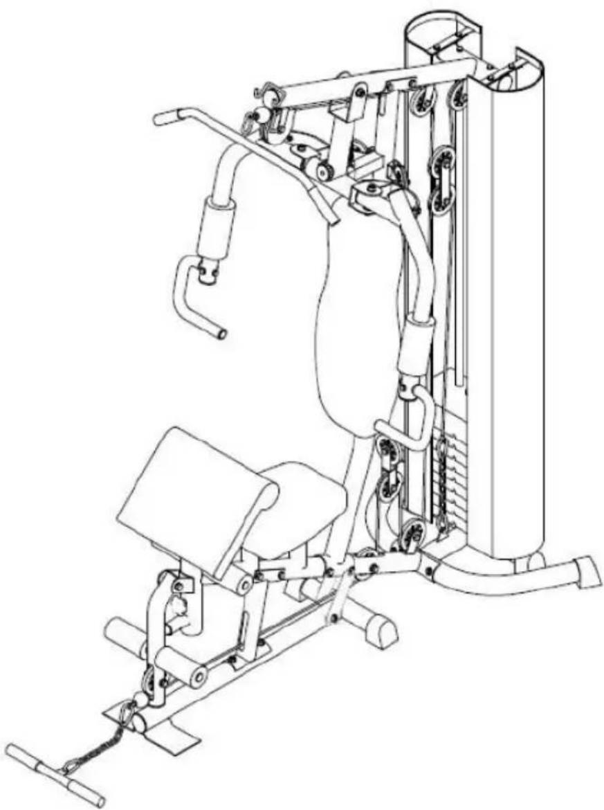
Line drawing of a gym machine with adjustable arms and legs (no text or symbols)- Simply insert the weight pin into your desired weight and lift
- Easy for doing pull ups, pullovers, pull-down using the lateral bars
• Providing leg workouts as well by pulling with foot wrap - Adjustable bicep pad
SAFETY & WARNINGS
General Safety Warnings
Before using this equipment, it is essential that you read the entire user guide, including all warnings and safety instructions. Ensure you convey all such warnings and instructions to any other person using this product. Retain this user guide for future reference.
Safety
Important: Before beginning any exercise program, consult your physician. This is especially important for individuals over the age of 35 or persons with pre-existing health problems. Read all instructions before using any fitness equipment.
- Before beginning any exercise program, consult your physician for a physical examination.
- If you have any known medical condition or any physical limitation on your ability to exercise, seek the advice of a physician before using the machine, in order to avoid possible personal injury.
- If while using the machine, you experience any dizziness, faintness, shortness of breath or pain, cease use immediately and consult your physician. Failure to do so could result in personal injury.
- Do not use the equipment while tired or under the influence of drugs, alcohol or other medication.
- Replacement parts must be specific to this product and supplied by Kogan.com only. Unauthorised substitutions may result in bodily injury or equipment damage.
- The home gym should be set up on a hard, level surface in an area free of obstructions.
- The machine should not be used outdoors, near a pool or near any source of water or extreme humidity
- Do not use this machine for anything other than intended purposes.
- Always wear appropriate workout clothing when exercising. DO NOT wear robes or other clothing that could become caught in the machine. Running or aerobic shoes are also required when using the machine.
- This product is not intended for use by persons (including children) with reduced physical, sensory or mental capabilities or lack of experience and knowledge, unless they have been given supervision or instruction concerning use of the product in a safe way by the person responsible for their safety, and understand the hazards involved.
- Never operate the machine if it is not functioning properly.
• Always keep hands away from all moving parts.
OVERVIEW

| Part | Description | Qty | Part | Description | Qty |
| 1 | Base Frame | 1 | 39 | M10 Nylon Nut | 27 |
| 2 | Seat post | 1 | 40 | M12 Nylon Nut | 5 |
| 3 | Rear Stabiliser | 1 | 41 | Fixed Pin for Weight Stack | 1 |
| 4 | Seat Support Tube | 1 | 42 | End Cap | 6 |
| 5 | Upright Support Tube | 1 | 43 | Φ60 Round Cap | 2 |
| 6 | Leg Curl Tube | 1 | 44 | Φ60 Flat Cap | 2 |
| 7 | Guiding Tube | 2 | 45 | Φ50 Flat Cap | 8 |
| 8 | Bridge Tube | 1 | 46 | Φ25 Flat Cap | 6 |
| 9 | Pull unit | 1 | 47 | Pin | 1 |
| 10L | Butterfly Arm – Left | 1 | 48 | Rubber Ring | 2 |
| 10R | Butterfly Arm – Right | 1 | 49 | Pulley | 11 |
| 11 | Handlebar | 2 | 49A | Pulley A | 1 |
| 12 | Lat Bar | 1 | 50 | Cap for Small Pulley | 2 |
| 13 | Lower Pull Bar | 1 | 51 | Plastic Bushing | 4 |
| 14 | Foam Tube for Leg curl | 2 | 52 | Rubber Stopper | 1 |
| 15 | Bracket for Seat/Backrest | 2 | 53 | Foam for Butterfly Arm | 2 |
| 16 | Hex Head Bolt M12x80mml | 2 | 54 | Foam for Leg Curl | 4 |
| 17 | Bracket for Pulley | 2 | 55 | Foam for Handlebar | 2 |
| 18 | Two Way Bracket for Pulley | 1 | 56 | Hand Grip | 4 |
| 19 | Select Bar | 1 | 57 | Round Cap for Select Bar | 1 |
| 20 | Pulley Bracket | 2 | 58 | Round Cap for Select Bar | 1 |
| 21 | Axle for Pull Unit | 1 | 59 | Back cushion | 1 |
| 22 | Hex Head Bolt M8 x 20mmL | 8 | 60 | Seat | 1 |
| 23 | Hex Head Bolt M10 x 60mm | 2 | 61 | Chain 8 Links | 2 |
| 24 | Hex Head Bolt M8 x 15mm | 22 | 62 | Hook | 5 |
| 25 | Hex Head Bolt M10 x 40mm | 9 | 63 | Weight Stack 8 Lbs | 1 |
| 26 | Hex Head Bolt M10 x 45mm | 1 | 64 | Weight Stack 10 Lbs | 9 |
| 27 | Hex Head Bolt M10 x 75mm | 4 | 65 | Cable for Lat Bar | 1 |
| 28 | Hex Head Bolt M10 x 70mm | 1 | 66 | Cable for Butterfly Arm | 1 |
| 29 | Hex Head Bolt M12 x 80mm | 1 | 67 | Cable for Lower Pull Bar | 1 |
| 30 | Hex Head Bolt M10 x 80mm | 6 | 68 | Cushion Support tube | 1 |
| 31 | Powder Metal Ring Φ12 | 4 | 69 | Bushing | 1 |
| 31A | Powder Metal Ring Φ16 | 2 | 70 | Stopper | 1 |
| 32 | Select Pin | 1 | 71 | Knob | 1 |
| 33 | Curve Washer OD20XID8.3 | 7 | 72 | Elbow Cushion | 1 |
| 34 | Curve Washer OD23XID10 | 6 | 73 | Bracket for Cloth Cover | 4 |
| 35 | Flat Washer OD23XID10 | 28 | 74 | Spring | 1 |
| 35A | Flat Washer OD23XID9 | 22 | 75 | Cloth Cover for Left/Right | 2 |
| 36 | Flat Washer OD24XID12.3 | 8 | 76 | Plum-nut | 1 |
| 37 | Flat Washer OD40XID12.5 | 1 | 77 | Hex Head Bolt M10x85mm | 1 |
| 38 | M8 Nylon Nut | 2 | 78 | Connection strap | 2 |
ASSEMBLY
Step A:

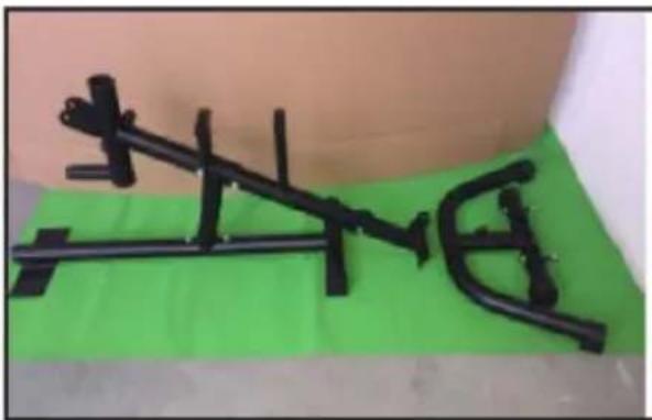
- Attach the seat post (02) to the Base Frame (01) using x2 hex head bolts (27), x4 curve washers (34) and x2 nylon nuts (39).

natural_image
Two photos showing a person adjusting a black mechanical bracket on a green mat, no text or symbols visible.- Attach the seat support tube (04) to the seat post (02) using x2 hex head bolts (30), x4 flat washers (35) and x2 nylon nuts (39).

- Attach the rear stabilizer (03) to the seat support tube (04) using x2 hex head bolts (27), x4 curve washers (34) and x2 nylon nuts (39).
natural_image
Metal bracket with green base on white surface, no visible text or symbols
natural_image
Close-up of hands assembling a black plastic car body on a green surface (no text or symbols visible)- Attach the guiding tube (07) to the rear stabilizer (03), attach the upright support tube (05) to the seat support tube (04) and tighten using x2 hex head bolts (30).

natural_image
Close-up of hands holding a small metallic object on a green surface (no visible text or symbols)
natural_image
Close-up of a hand adjusting a black metal pipe fitting with screws, against a green background (no text or symbols visible)
natural_image
Close-up of a black mechanical component mounted on a green surface, with no visible text or symbols.
natural_image
Person in orange jacket using a mechanical device on a green surface (no visible text or symbols)Step B:
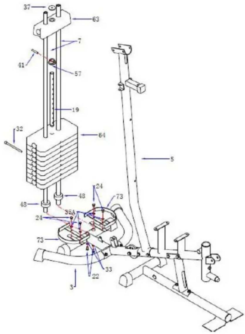
- Attach the bracket for cloth cover (left side) (73) to the rear Stabiliser (03) and tighten using x2 hex head bolts (24), x2 washers (35A).
- Do the same for the bracket for the cloth cover (73) to the right side of the rear Stabiliser (03) and tighten using x2 hex head bolts (24), x2 washers (35A).
natural_image
Close-up of a black bicycle bike handle with metal frame and green background (no text or symbols visible)
natural_image
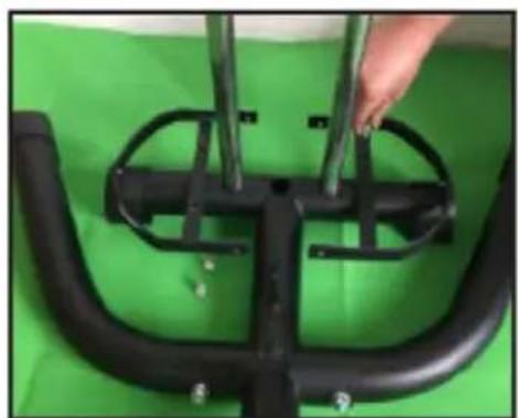
Close-up of a black bicycle brake lever against a green background (no text or symbols visible)- Slide both guiding tubes (07) through the rubber rings (48) and into the two holes on the rear Stabiliser (3) tighten from the bottom side using x2 curve washers (33) and x2 head hex bolts (22).

natural_image
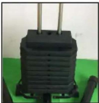
Hand holding a black plastic cap above two metallic cylindrical objects (no text or symbols visible)- Place the weight stack (64) into position ensure the guiding tubes (07) are fed through the holes.
natural_image
Close-up of a black industrial transformer with three vertical leads, placed on a green surface (no visible text or symbols)- Place the bushing for weight stack (57) onto the select bar (19) and secure in place using the fixed pin (41). Place the weight stack (63) on the select bar (19) and place flat washer (37) onto the weight stack (63).

natural_image
Close-up of a hand holding a black metal frame with vertical supports, against a plain background (no text or symbols visible)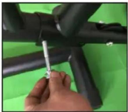
natural_image
Close-up of a hand using a screwdriver to adjust or install black cylindrical components against a green background (no text or symbols visible)- Insert the select pin (32) through the weight stack (64) and into the hole in the select bar (19).

natural_image
Black industrial electrical plug device with coiled cable and green base (no visible text or symbols)Step C:

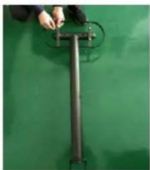
- Attach the bracket for cloth cover (73) into the bridge tube (08) using x4 hex head bolts (24) and attach the guiding tube (07) to the bridge tube (08) into using x2 hex head bolts (22).
natural_image
Close-up of a hand adjusting a metal T-shaped object on a green surface (no text or symbols visible)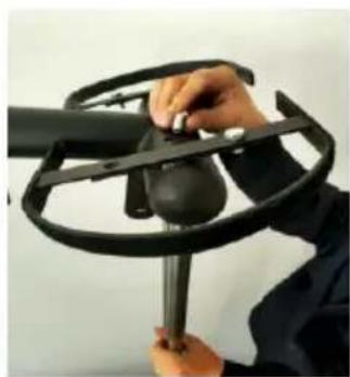
natural_image
Person using a metal detector device to handle a black dome component (no visible text or symbols)
natural_image
Person using a tool to adjust or install a black metal bracket (no text or symbols visible)
natural_image
Close-up of a black metal frame with a red-handled tool inserted, mounted on a vertical support structure (no visible text or symbols)- Attach the bridge tube (08) to the upright support tube (05) and secure using x2 hex head bolts (30), x4 flat washers (35) and x2 nylon nuts (39).

natural_image
Close-up of a black industrial device with coiled tubing and a green base (no visible text or symbols)- Attach the base frame (01) to the upright support tube (05). Following the diagram attach the x2 connection straps (78) and using a hex head bolt (30), hex head bolt (77) x2 flat washers (34) and x2 nylon nuts (39).
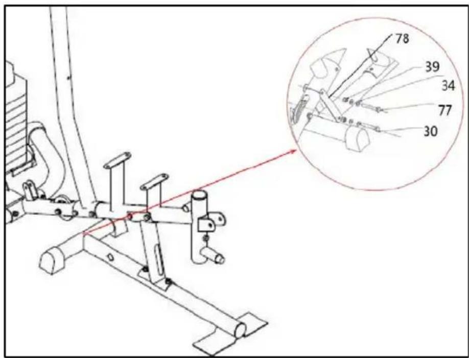
Step D:
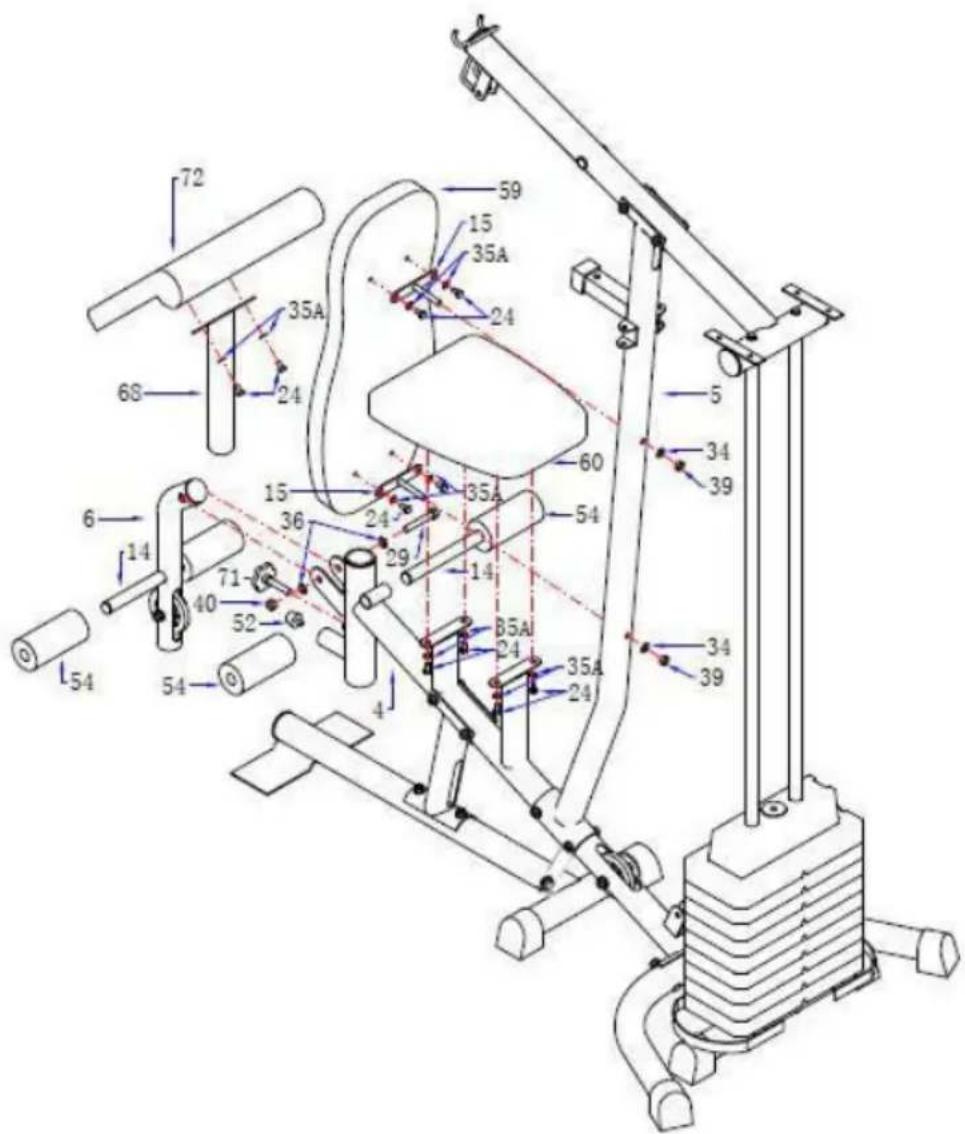
- Attach the bracket for backrest (15) to the back cushion (59), tighten using x2 flat washers (35A) and x2 hex head bolts (24).

natural_image
Close-up of a hand adjusting a small metallic component on a green surface (no visible text or symbols)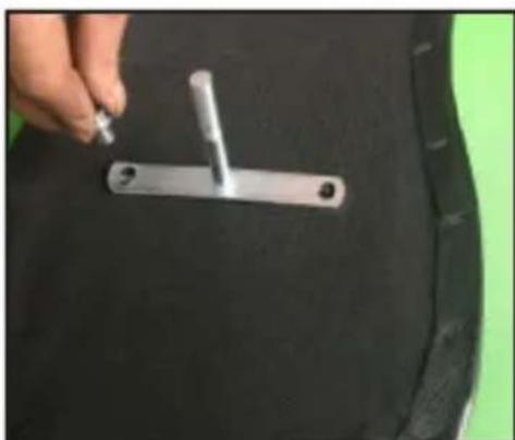
natural_image
Close-up of a hand holding a metal bracket with a small tool, placed on a dark fabric surface (no text or symbols visible)- Attach the backrest cushion (59) to the upright support tube (05) by putting the screw on the bracket for backrest (15) into the hole in the upright support tube (05) and secure using a curve washer (34) and M10 nylon nut (39).
- Attach the seat (60) onto the seat support tube (04) by putting the screw on the bracket for seat into the holes and secure using x4 flat washers (35A), x4 hex head bolts (24).

natural_image
Close-up of a hand holding a black ergonomic chair with a white clip, no visible text or symbols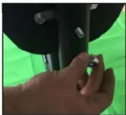
natural_image
Close-up of a hand adjusting a small object against a green background (no visible text or symbols)
natural_image
Close-up of a hand adjusting a black mechanical component against a plain background (no text or symbols visible)- Attach the elbow cushion (72) onto the elbow cushion support tube (68) tighten using x2 washers (35A), x2 hex held bolts (24). Attach the elbow cushion support tube (68) into the seat support tube (04), then secure with the knob (71).

natural_image
Hand holding a small object over a black cylindrical object, placed on a green surface (no text or symbols visible)
natural_image
Person adjusting a black exercise bike frame on a green surface (no text or symbols visible)-
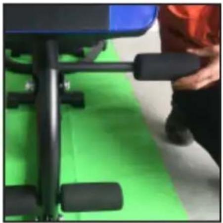
Screw-in the small rubber stopper (52) into the front side of seat support tube (04). Attach the leg curve tube (06) to the front side of seat support tube (04), tighten using hex head bolt (29), x2 flat washers (36) and a nylon nut (40).
-
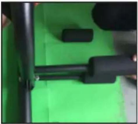
Attach the x2 foam tube for leg curl (14) into the holes on leg curl tube (06) and front/upper bracket of seat support tube (04).
natural_image
Close-up of a person's armrest with black legs and green cushion, no visible text or symbols- Attach the x2 foam for leg curl tube (54) onto both sides of each foam tube for Leg Curl (14).
natural_image
Close-up of black mechanical components on a green surface, no visible text or symbolsStep E:
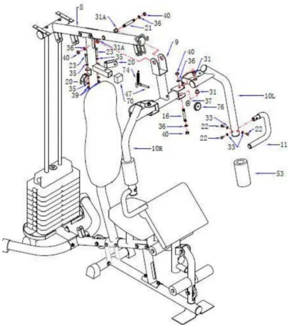
- Attach the pull unit (09) to the bridge tube (08), insert the axle for pull unit (21) and secure using x2 Powder Metal Rings (31A), x2 Flat washers (36) and x2 Nylon Nuts (40) (refer to Step E diagram).

natural_image
Close-up of a black and green mechanical device with curved and straight ends (no visible text or symbols)- Attach the butterfly arm R (10R) to the right side of pull unit (09) using x2 powder metal rings (31), a hex head bolt (16) and x2 flat washers (36) and tighten using a x2 nylon nuts (40)
Repeat the same procedure for the butterfly arm L (10L).

- Place the rubber stopper (70) onto the bracket on the upright support tube (05). Then adjust the Pull Unit (09) to match the hole in the bracket

natural_image
Technical line drawing of a mechanical assembly with a 70-degree angle indicator (no text or symbols present)- Put the foam for butterfly arm (53) onto the R/L butterfly arm (10R & 10L) and adjust to desired position.

natural_image
Hand holding a black cylindrical object with a vertical stack of black objects nearby (no visible text or symbols)- Attach the handlebar (11) onto the butterfly arm R (10R), tighten using x3 curve washers (33) and x3 hex head bolt (22).
Repeat the procedure for butterfly arm L (10L) with the other handlebar (11L).

- Attach the x2 pulley brackets (20) onto both sides of the upright support tube (05) tighten using x2 hex head bolts (23), x4 flat washers (35) and x2 nylon nuts (39).

Step F:
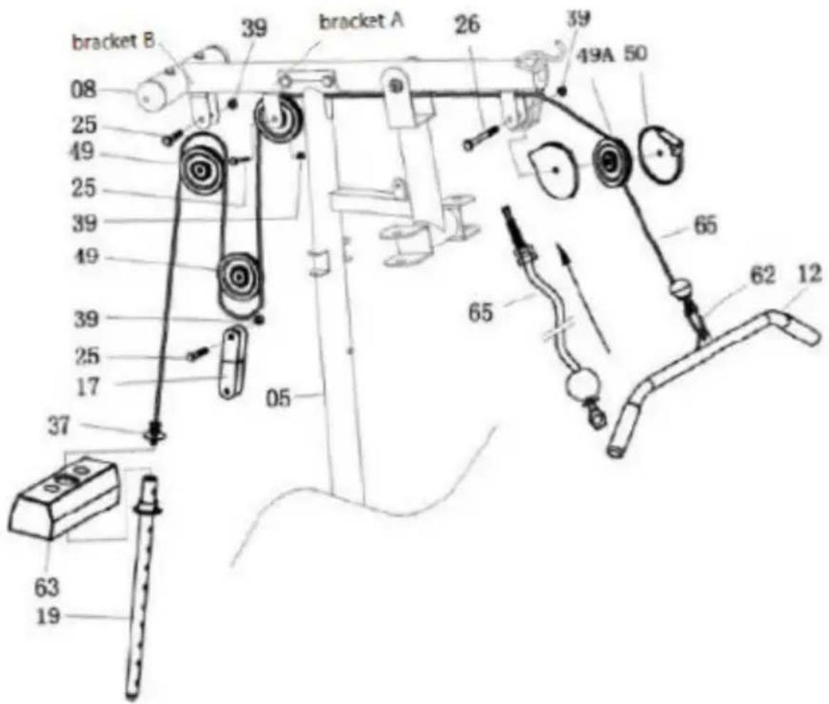
- Attach the cable for lat bar (65) to the opening bracket at the front of the bridge tube (8).
Note: The ball stopper of the Cable (65) should be underneath the bridge tube (8). Attach the cable (65) onto the pulley (49A) and put the cap for pulley (50) on either side of pulley (49A).
Note: The Cable (65) has to come out of the cap (50) from the opening sides. Tighten to the bracket using a hex head bolt (26) and nylon nut (39).
-
Draw the cable (65) towards the back side of the machine through the upper opening of upright support tube (05) and around pulley (49), then attach the pulley (49) onto bracket A (refer to Step F diagram), tighten using a hex head bolt (25) and a nylon nut (39).
-
Draw the cable (65) downwards and around Pulley (49). Attach the Pulley (49) with the bracket for pulley (17) on both sides then tighten using a hex head bolt (25) and a nylon nut (39).
- Draw the cable (65) upwards and around Pulley (49). Attach the pulley (49) to bracket B and tighten using a hex head bolt (25) and a nylon nut (39) (refer to Step F diagram)
- Draw the cable (65) downwards between the two guiding tubes (07) and fully thread the bolt on the end of the cable (65) into the top opening on the select bar (19).
- Attach the lat Bar (12) to the front end of the cable (65), connect using hook (62).
Step G:

-
Attach one end of the cable for butterfly arm (66) to the hook on the right butterfly arm (10R), tighten using a hex head bolt (24), a flat washer (35A) and a nylon nut (38).
-
Feed the cable (66) around the pulley (49) then attach the pulley (49) to the pulley bracket (20) on the right side of the upright support tube (05), tighten using a hex head bolt (25) and a nylon nut (39).
-
Feed the other end of the cable (66) downward and around the pulley (49), attach the pulley (49) to the upper part of the 2-way bracket for pulley (18) and tighten using a hex head bolt (25) and a nylon nut (39).
-
Feed the cable (66) upward and around pulley (49). Attach pulley (49) to the pulley bracket (20) on the left side of the upright support tube (05), tighten using a hex head bolt (25) and a nylon nut (39).
- Attach the end of the cable (66) to the hook on the left butterfly Arm (10L), tighten using a hex head bolt (24) and a flat washer (35A) and a Nylon Nut (38).
Step H:
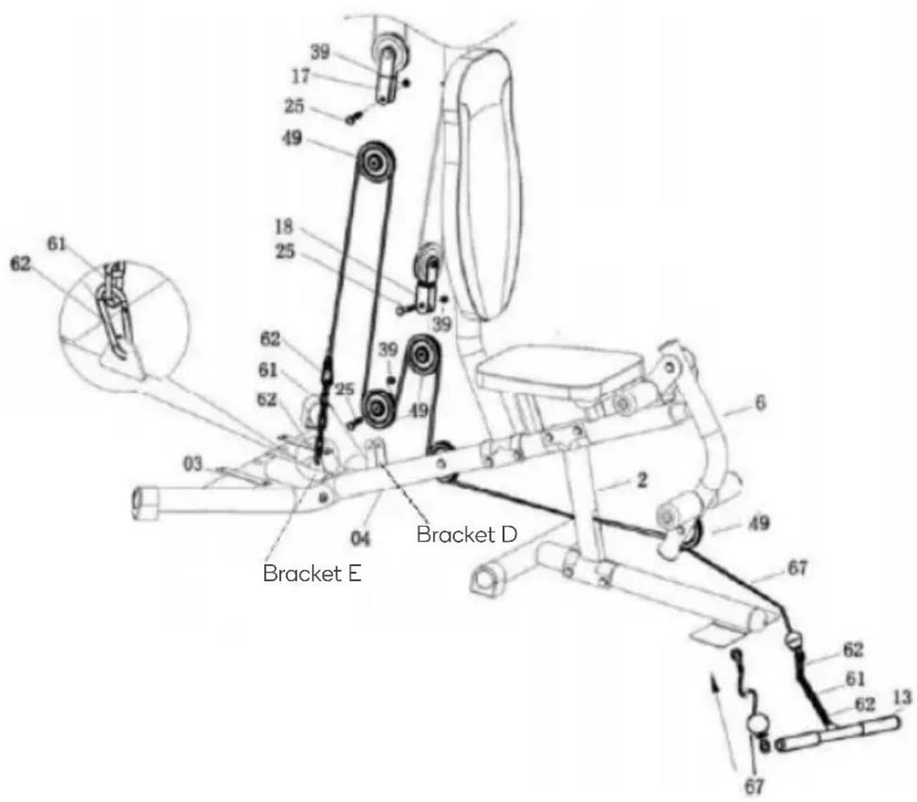
- Attach the end with the stopper ball of the cable for lower pull bar (67) to the open bracket leg curl (6), around the underside of Pulley (49).
Feed the cable (67) through the opening on the lower part of the seat post (02), around the pulley (49) from under side then draw the cable (67) upward and around the upper side of pulley (49).
Attach the pulley (49) to the underside of the 2-Way bracket for pulley (18), tighten using a hex head bolt (25) and a nylon nut (39).
-
Feed the Cable (67) downward and around the underside of Pulley (49). Attach the Pulley (49) to bracket D on the seat post tube (4) and tighten using a hex head bolt (25) and a nylon nut (39).
-
Draw the Cable (67) upward and around the upper side of Pulley (49). Attach the Pulley (49) to the underside of Bracket for Pulley (17) set and tighten using a hex head bolt (25) and a nylon nut (39).
- Feed the Cable (67) downward and connect with bracket E on rear stabiliser (3) using chain links (61) and x2 Hooks (62).
Note: Adjust the Cable (67) to be tight enough and lock in the desired position of the chain (61) using Hook (62).
- Attach the lower pull bar (13) to the front end of Cable (67), connecting using chain 8 links (61) and x2 hooks (62) (refer to Step G diagram).
Step I:

- Attach the bracket for the cloth cover L (73) to the bridge tube (08) and tighten using the x2 hex head bolts (24) and x2 flat washers (35A).

natural_image
Close-up of a hand using a black cable to cut a black mesh component (no text or symbols visible)
natural_image
Close-up of a black mesh device with a circular button and grid pattern, no visible text or symbols
natural_image
Close-up of a black exercise machine with pulleys and a white X mark on its side (no visible text or symbols)NOTES
Need more information?
We hope that this user guide has given you the assistance needed for a simple set-up.
For the most up-to-date guide for your product, as well as any additional assistance you may require, head online to help.kogan.com
kogan.com


Brand : Fortis
Model : FSGYMSTN45A
Category : Fitness Equipment