WR1000 - Rowing Machine York Fitness - Free user manual and instructions
Find the device manual for free WR1000 York Fitness in PDF.


| Product Type | Water Resistance Rower |
| Brand | York Fitness |
| Model | WR1000 |
| Resistance Mechanism | Water turbine (impeller) |
| Resistance Adjustment | By water level (1 to 6) |
| Console Type | Digital LCD |
| Display Metrics | Time, Time/500M, SPM, Distance, Strokes, Total Strokes, Calories, Pulse |
| Programs | Manual, Race (15 levels), Recovery |
| Power Supply | 2 AA batteries (included) |
| Water Tank Capacity | Max fill level 6 (specific volume not provided) |
| Seat | Sliding along rail |
| Foot Pedals | Adjustable straps |
| Transport Wheels | Yes (on front stabilizer) |
| Storage | Vertical storage possible |
| Warranty (Frame) | Lifetime (domestic use) |
| Warranty (Parts) | 1 year (domestic use) |
| Intended Use | Residential only |
| Assembly Required | Yes (2 people recommended) |
| Included Accessories | Funnel, pumping siphon, water purification tablet, tools (Allen wrench S5, Spanner S13-17) |
| Pulse Monitoring | Compatible with optional 5.3kHz chest strap (not included) |
| Bungee Cord Adjustment | 3 hooks for return assist |
Frequently Asked Questions - WR1000 York Fitness
User questions about WR1000 York Fitness
0 question about this device. Answer the ones you know or ask your own.
Ask a new question about this device
Download the instructions for your Rowing Machine in PDF format for free! Find your manual WR1000 - York Fitness and take your electronic device back in hand. On this page are published all the documents necessary for the use of your device. WR1000 by York Fitness.
USER MANUAL WR1000 York Fitness
natural_image
Technical line drawing of a rowing machine with levers and wheels (no text or symbols)Important Safety Instructions 1
WR1000 Water Resistance Rower Assembly Instructions 3
Operation of Your Console 15
Troubleshooting 20
Parts List 21
ATTENTION
THIS ROWER IS INTENDED FOR RESIDENTIAL USE ONLY AND IS WARRANTED FOR THE APPLICATION. ANY OTHER APPLICATION VOIDS THIS WARRANTY IN ITS ENTIRETY.
Important Safety Instructions
When using an electrical appliance, basic precautions should always be followed, including the following:
Read all instructions before using this appliance.
DANGER - To reduce the risk of electric shock:
- Always unplug this appliance from the electrical outlet immediately after using and before cleaning.
WARNING - To reduce the risk of burns, fire, electric shock, or injury to persons:
- An appliance should never be left unattended when plugged in. Unplug from outlet when not in use, and before putting on or taking off parts.
- Do not operate under blanket or pillow. Excessive heating can occur and cause fire, electric shock, or injury to persons.
- Close supervision is necessary when this appliance is used by, on, or near children, invalids, or disabled persons.
- Use this appliance only for its intended use as described in this manual. Do not use attachments not recommended by the manufacturer.
- Never operate this appliance if it has a damaged cord or plug, if it is not working properly, if it has been dropped or damaged, or dropped into water.
- Do not carry this appliance by the supply cord or use the cord as a handle.
- Keep the cord away from heated surfaces.
- Never operate the appliance with the air openings blocked. Keep the air openings free of lint, hair, etc.
- Never drop or insert any object into any opening.
- Do not use outdoors.
- Do not operate where aerosol (spray) products are being used or where oxygen is being administered.
- Connect this appliance to a properly grounded outlet only.
- The appliance is intended for household use ONLY.
Fitness Equipment Safety Instructions
- To disconnect, turn all controls to the off position, then remove the plug from the outlet.
- Do not operate equipment on deeply padded, plush or shag carpet. Damage to both carpet and equipment may result.
- Before beginning this or any exercise program, consult a physician. This is especially important for persons over the age of 35 or persons with pre-existing health conditions.
- Keep hands away from all moving parts.
- The pulse sensors are not medical devices. Various factors, including the user's movement, may affect the accuracy of heart rate readings. The pulse sensors are intended only as exercise aids in determining heart rate trends in general.
• Do not attempt to use your equipment for any purpose other than for the purpose it is intended. - Wear proper shoes. High heels, dress shoes, sandals or bare feet are not suitable for use on your equipment. Quality athletic shoes are recommended to avoid leg fatigue.
Failure to follow all guidelines may compromise the effectiveness of the exercise experience, expose yourself (and possibly others) to injury and reduce the longevity of the equipment.
SAVE THESE INSTRUCTIONS - SAFETY FIRST!
CAUTION!! Please be careful when unpacking the carton.
Before you begin
Thank you for selecting our revolutionary York Fitness WR1000 Water Resistance Rower. A rower is an effective exercise for increasing cardiovascular fitness, building endurance, and toning the body. Our Water Resistance Rower provides an impressive selection of features designed to make your workouts at home more effective and enjoyable.
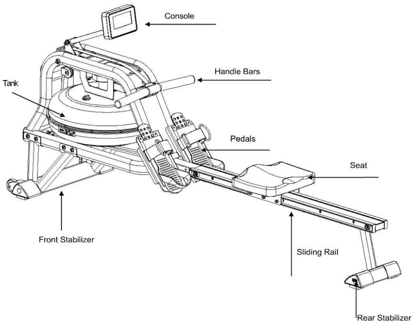
For your benefit, read this manual carefully before you use the York Fitness WR1000 Water Resistance Rower. To help us assist you, note the product model number and serial number before contacting us. Before reading further, please familiarize yourself with the parts that are labeled in the drawing below.
PRE-ASSEMBLY CHECK LIST
natural_image
Technical line drawing of a mechanical device with no visible text or symbolsNO.1
natural_image
Technical line drawing of a metal bracket with four vertical supports (no text or symbols)NO.2 NO.4
natural_image
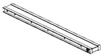
Isometric line drawing of a long rectangular metal beam or support structure (no text or symbols)NO.3
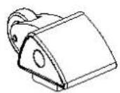
NO.25
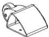
NO.26
natural_image
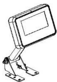
Technical line drawing of a mechanical support bracket with mounting base (no text or symbols)NO.46

NO.82

NO.83

NO.35
natural_image
Line drawing of a rectangular electronic device with mounting feet (no text or symbols)NO.36
NO.77 NO.76
Water Purification tablet
Parts List
| PART NO. | DESCRIPTION | Q'TY |
| 1 Main Frame 1 | ||
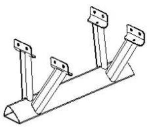
| 2 Front Stabilizer 1 | ||
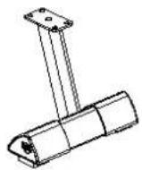
| 4 Rear Stabilizer 1 | ||
| 3 Slide Rail 1 | ||
| 25 Left End Cap 1 | ||
| 26 Right End Cap 1 | ||
| 46 | Console | 1 |
| 82 | Rail Endcap L | 1 |
| 83 | Rail Endcap R | 1 |
| 35 Stopper 2 | ||
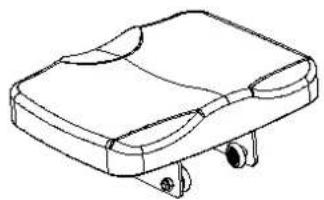
| 36 Seat 1 | ||
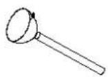
| 77 Funnel | 1 | |
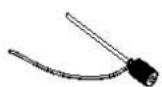
| 76 | Pumping Siphon | 1 |
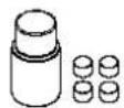
| Water-purification tablet | 1 | |
| User manual | 1 | |
| Hardware parts | 1 | |
Note: Above parts are all needed to assemble this machine. Before you start to assemble, please check the hardware packaging to make sure everything is included. If anything is missing, please contact Spares@bfe.com.au
HARDWARE PARTS LIST
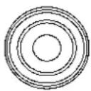
35 Stopper 2pcs

58 M8*15 4pcs
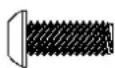
60 M8*18 14pcs
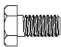
66 M8*15 4pcs
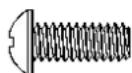
68 M4*12 2pcs
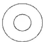
71 OD20*ID8.5*1.5 16pcs
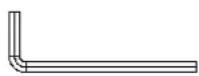
74 S5 1pc
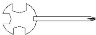
75 S13-17 1pc
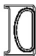
82 Rail EndcapL 1pc
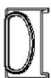
83 RailEndcapR 1pc
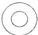
87 OD16*ID8.5*1.5 2pcs
Assembly Instructions
1 Rear Stabilizer
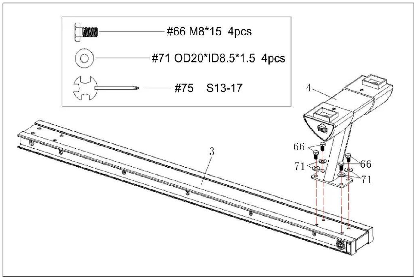
NOTE: We recommend having 2 people to assemble the product.
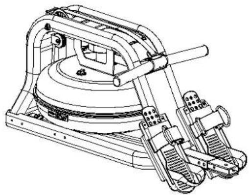
- Turn over the Slide Rail (No. 3) as above. Attach the Rear Stabilizer (No.4) to the Slide Rail with 4 Washers (No.71) and 4 Outer Hex Screws (No.66).
- Tighten with Spanner (No.75).
2 Front Stabilizer End caps
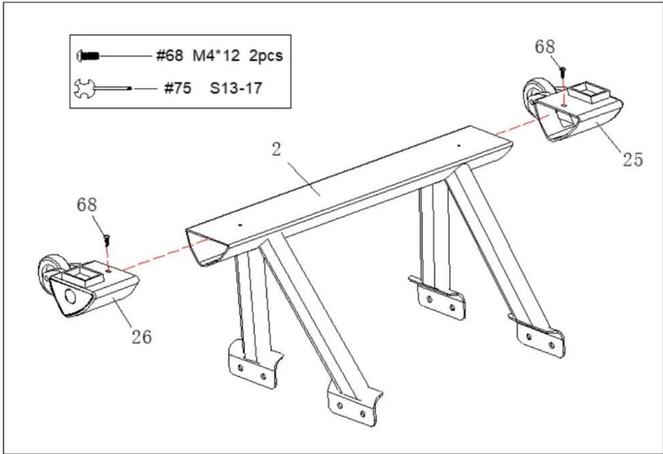
- Attach L & R End Caps (No.25 & 26) to Front Stabilizer (No.2). Then tighten with 2 Cross Screws (No.68) using the Spanner (No.75).
3 Attaching the Front Stabilizer
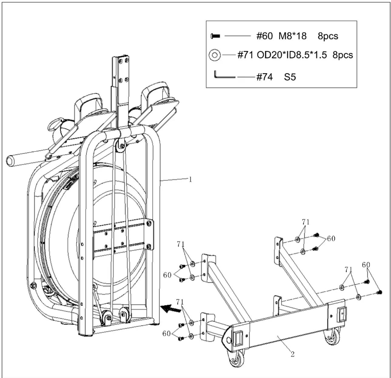
- Turn the Main Frame (No.1) upright. Attach the Front Stabilizer (No.2) to Main Frame (No.1) using 8 Washers (No.71) and 8 Screws (No.60). Tighten with Allen Wrench (No.74).
- You can put 3\~4 screws into the holes first and start tightening by hand. After all the screws are put in, then tighten with the tool.
4 Seat and Rail
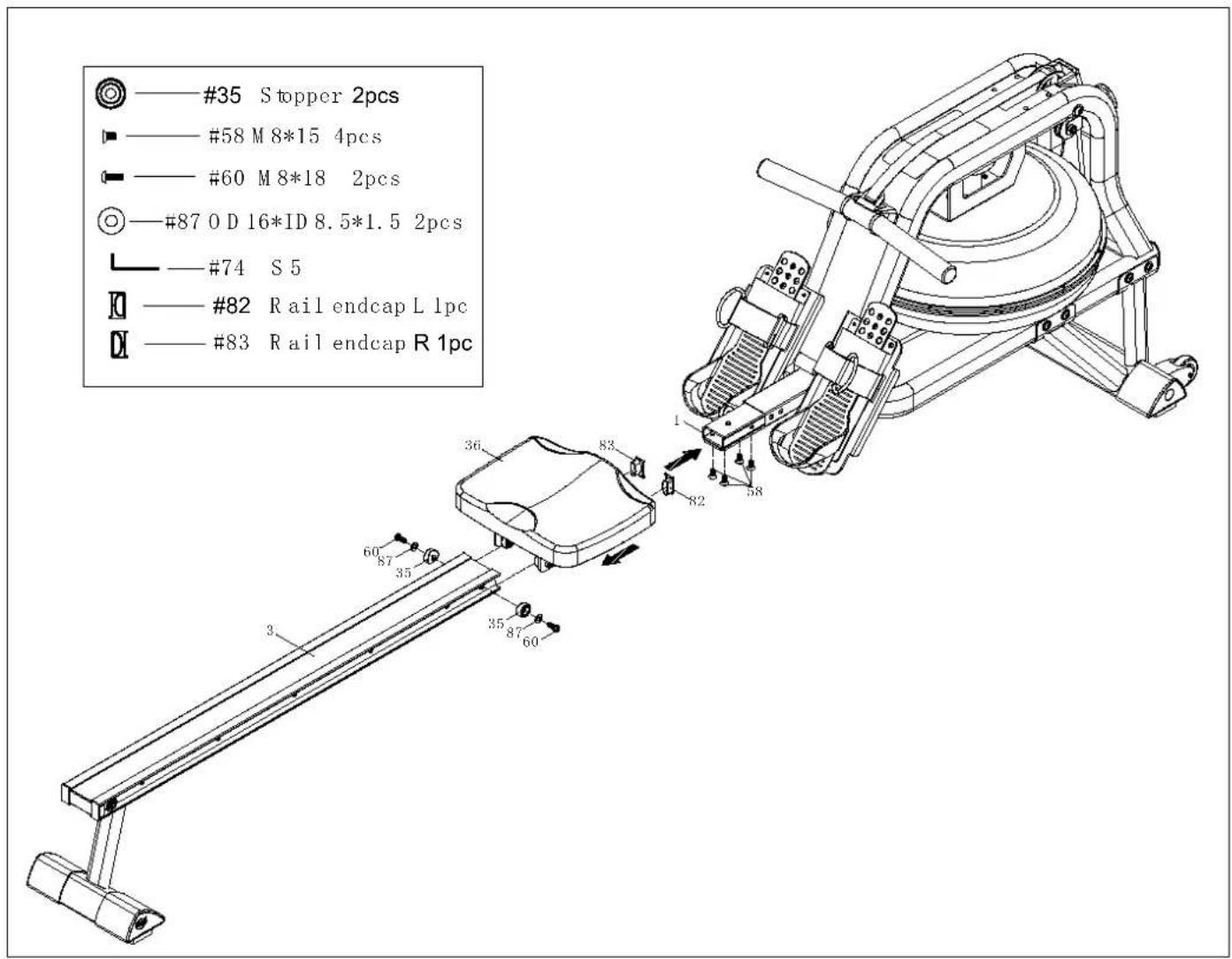
- Slide the Seat (No.36) onto the Slide Rail (No.3).
- Attach the Slide Rail (No. 3) to the Main Frame (No. 1) using 4 Flat Screws (No. 58).
- Secure the Stopper (No.35) with 2 Screws (No.60) and Washers (No.87). Insert all 6 screws partially into the holes first, and then tighten with Allen Wrench (No.74).
- Attach Rail end cap L(No.82) and Rail end cap R(No.83) to the Slide Rail (No.3).
5 Console
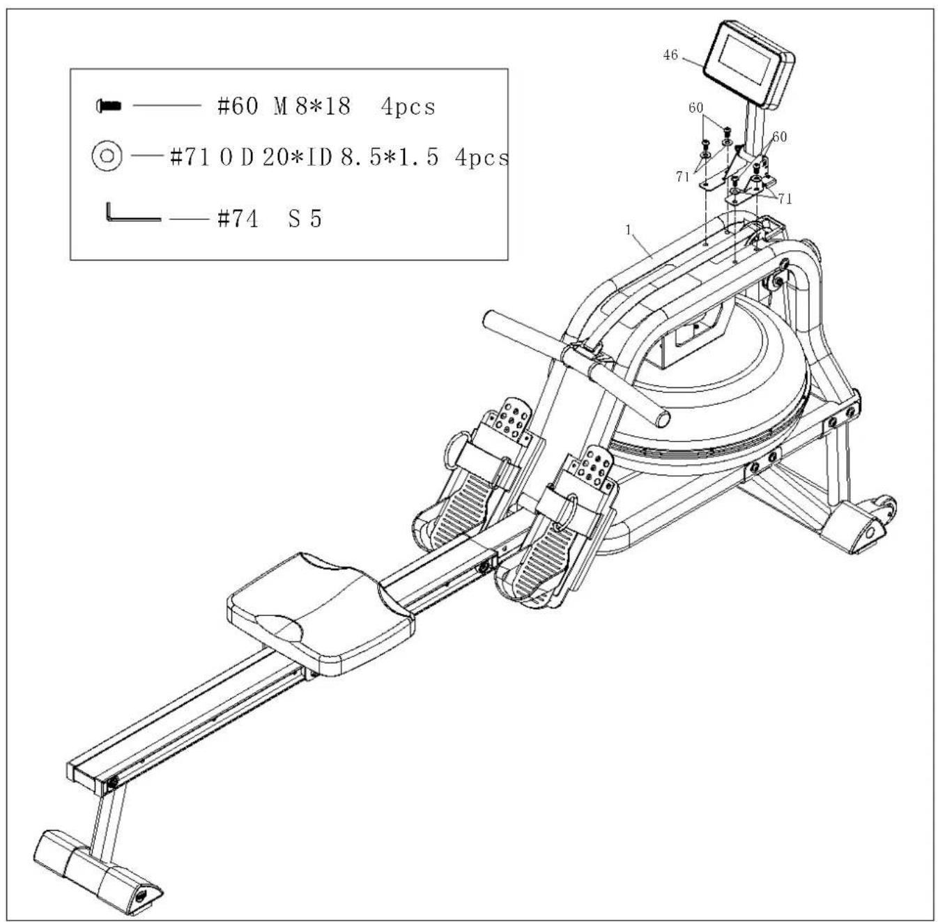
- Attach Console (No.46) to Main Frame (No.1) using 4 Washers (No.71) and 4 Screws (No.60). Tighten with Allen wrench (No.74).
How to Fill and Empty the Tank
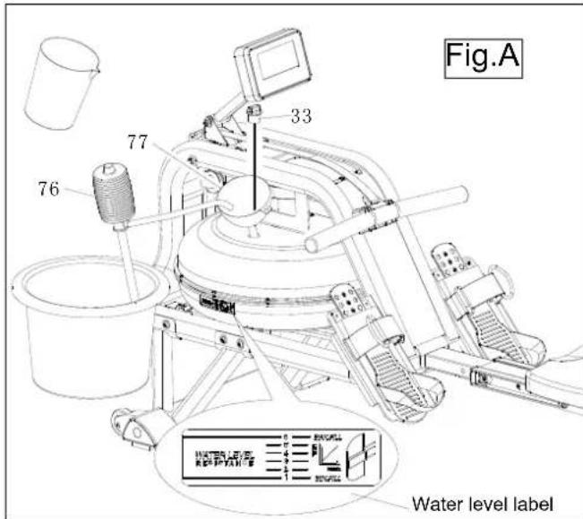
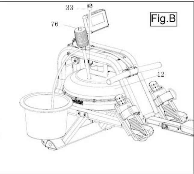
- Remove the Fill Plug (No.33) from the Upper Tank Cover (No.12).
- To fill tank with water, refer to Fig. A. Insert the Funnel (No.77) into the tank, then use a cup or the Siphon Pump (No.76) and a bucket to fill the tank. Use the water level gauge on the side of the tank to measure desired water level in the tank.
- To empty the tank, refer to Fig. B. Place a bucket next to the rower, and use the Siphon Pump (No.76) to pump out the water from the tank into the bucket.
- Insert the Fill Plug (No.33) into the Upper Tank Cover (No.12). Wipe excess water off the frame.
NOTE:
- Fill the tank only with tap water. Add 1 water-purification tablet (1 packet is included.). Never use pool chlorine or chlorine bleach. This will damage the tank and void the warranty.
- Add a water purification tablet every 6 months or as needed. If water remains cloudy, replace the water in the tank.
● Water from the tank is not suitable for consumption. Dispose of the water after pumping it out from the tank.
WATER LEVEL
- See Fig. A. The water level gauge is on the side of the tank. The maximum fill level is 6. Never fill it over this limit. Filling the tank over this limit will void the warranty.
- The resistance depends on the water level in the tank. Water level 1 is the lowest resistance. Level 6 is the highest resistance.
Adjustment Guide
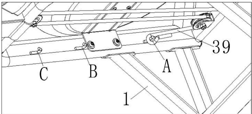
There are 3 hooks (A, B, C) for the bungee cord, located on the inside of the Frame (No.1) under the water tank. If you hook the Bungee Cord (No.39) on to B or C, it increases the assisted return of the mesh belt. C is the fastest return.
Use caution when adjusting the bungee cord.
Adjustment Guide and Storage
natural_image
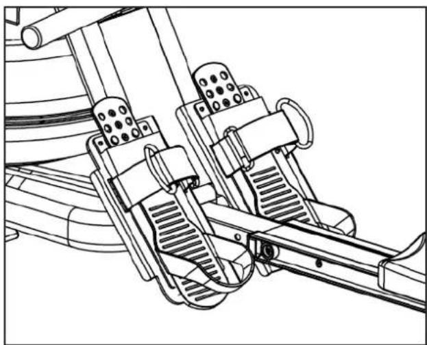
Technical line drawing of a mechanical device with levers and gears (no text or symbols)The pedal strap is adjustable and can be personalized to fit the user's foot size.
To adjust the pedal strap, remove the Velcro end of the strap from the mesh side by pulling it upward and over to the side.
Once removed, you may increase the opening of the pedal strap by pulling the mesh end up and to the side.
To tighten, pull the Velcro end of the pedal strap upward then over and down to secure it to the mesh side of the strap.
natural_image
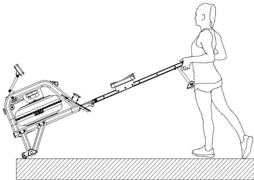
Line drawing of a person pushing a wheeled machine on a surface (no text or symbols)To move the machine, lift up the rear stabilizer until the transportation wheels on the front stand touch the ground. With the wheels on the ground, you can transport the rower to the desired location with ease.
Adjustment Guide
natural_image
Technical line drawing of a mechanical device with labeled component '4' and directional arrows indicating motion (no text or symbols beyond basic labels)Adjusting the Balance
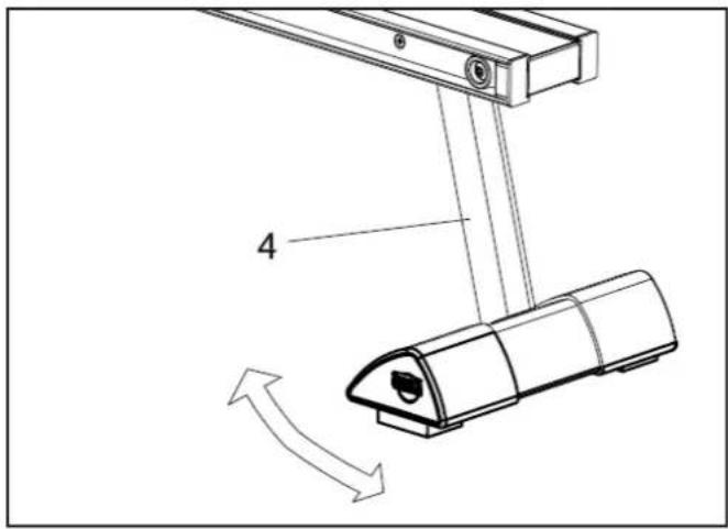
Adjust the End Caps on the Rear Stabilizer (No.4) of the machine if the machine is unbalanced during use.
CAUTION!
Moving parts, such as the seat, can crush and cut. Keep hands clear of the Slide Rail during use.
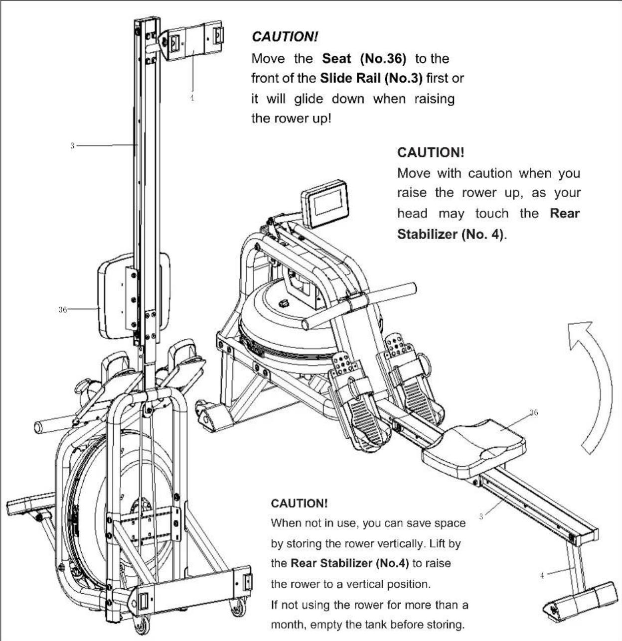
Operation of Your Console
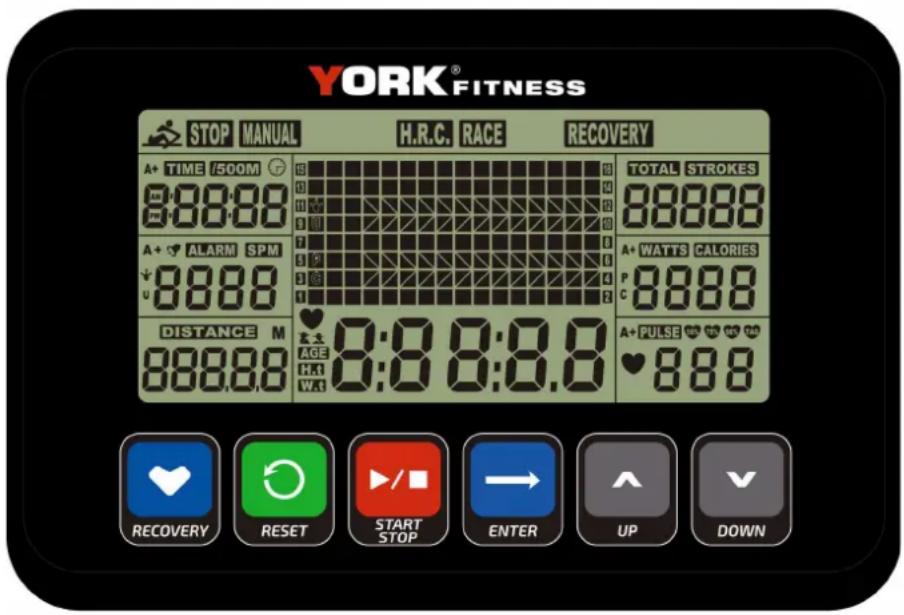
Our computerized display console on the WR1000 Water Resistance Rower allows the user to tailor a personalized workout by monitoring their progress. During a workout, the display console will alternately and repeatedly display the Time, Time/500M, SPM, Distance, Strokes, Total Strokes, Calories Burned and Pulse (all of the above).
Button Functions
UP / DOWN: Press these two buttons to scroll through available selection. To adjust the function value upward and downward.
ENTER: Press to confirm your selection during training, press the button to cycle scan each display function.
START / STOP: To start and stop your selected workout program.
RESET: To return the console back to the main menu. Press and hold to reset values.
RECOVERY: To activate the RECOVERY PROGRAM that will automatically evaluate your fitness immediately after your work out.
Functions
TIME: Set a target time by pressing the UP and/or DOWN buttons (1min \~ 99 min), in 1 minute increments.
TIME / 500M: Your average time to reach 500 metres is automatically displayed.
SPM: Strokes per minute.
DISTANCE: Preset a target value by pressing the UP and/or DOWN buttons (0 \~ 99900 meters), This is measured in 100 metre increments.
STROKES: Set a target value by pressing the UP and/or DOWN buttons (0\~9990 strokes). This is measured in 10 stroke increments.
TOTAL STROKES: Accumulates total strokes from 0 up to 9999.
CALORIES: Set a target value by pressing the UP and/or DOWN buttons (10\~9990 Cal). This is measured in 10 stroke increments.
PULSE: (Wireless chest strap sensor sold separately) - In Manual Mode, set the target heart rate value by pressing up/down (available range is 30 to 240 in 1 BPM increments). The console will display user's heart rate during training. When you are out of range of the target value during exercise, the console will beep and PULSE will blink until target range is resumed or wireless chest strap sensor is removed. The pulse measurement function is only usable with the optional wireless chest strap sensor.
CALENDAR: The console will display year, month, and day when console is in sleep mode.
TEMPERATURE: The console will display current room temperature when the console is in sleep mode.
CLOCK: The console will display current time when the console is in sleep mode.
Operation of Your Console
- Install 2 AA batteries (included) and the console will beep for 2 seconds (Fig.1). Then the console will enter into the CLOCK & CALENDAR MODE (Fig.2).
- The CLOCK will flash. Press UP / DOWN to set the hour. Press ENTER to confirm. Press UP / DOWN to set the minutes. Press ENTER to confirm. Continue to set up YEAR (in the STROKES window); MONTH (in the CALORIES window); DAY (in the PULSE window) by pressing UP or DOWN. Each time, press ENTER to confirm. After you confirm all values, the ALARM will blink. To skip setting up an alarm, press ENTER. To set up an alarm, press the UP KEY to turn on ALARM. An arrow will appear next to ALARM. Press ENTER. CLOCK window will flash. Press UP or DOWN to set the alarm time. Press ENTER to confirm. The console will then go into the SPORT screen (Fig.3).
- When you enter into the SPORT screen, MANUAL and RACE will blink. Press UP or DOWN to select MANUAL or RACE. Press ENTER to confirm your selection.
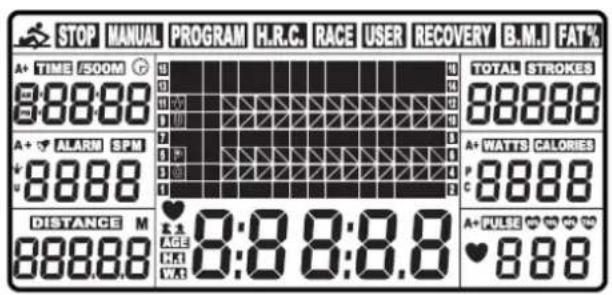
Fig. 1
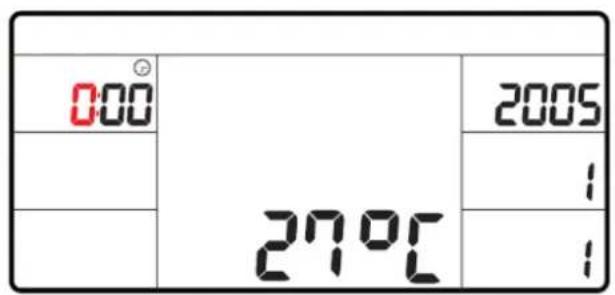
Fig. 2
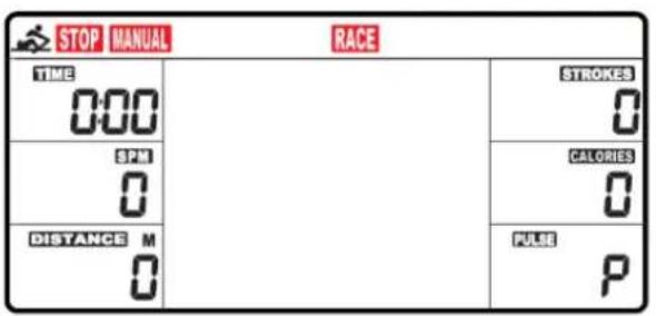
Fig. 3
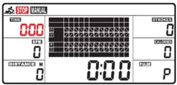
Fig. 4
Operation of Your Console
1. MANUAL (Fig.4): There are 2 options in MANUAL mode.
A. The console can be set to countdown a FKRVHQ value. When you select MANUAL, the value of TIME will start to flash. Press UP to set the value of TIME to countdown. Press ENTER to confirm it. If you do not want to set the value of time to COUNTDOWN, press ENTER to go to the next function. You=can set the values for DISTANCE, STROKES, CALORIES, or PULSE. (You can only set the=value for one function to countdown. For example, if you have set the target value for TIME, =then DISTANCE can't be set.) Press START button to start. The STOP icon will disappear.=When the function you have selected counts down to zero or you press KH STOP button, the=console will stop and display the average value.
B. The console counts the value of your=workout. Press START to start.
- RACE (Fig.5): Select RACE mode and L9 will flash. The TIME/500M will display 4:00. Then press UP or DOWN to select L1 \~ L15. Press ENTER to confirm. Then you can set the distance of the race (500M\~10000M) while the value of DISTANCE is blinking. Press ENTER and the picture of the race will display on the screen. The TIME/500M of the programs are as follows:
| L1 | L2 | L3 | L4 | L5 | L6 | L7 | L8 | L9 | L10 | L11 | L12 | L13 | L14 | L15 |
| 8:00 | 7:30 | 7:00 | 6:30 | 6:00 | 5:30 | 5:00 | 4:30 | 4:00 | 3:30 | 3:00 | 2:30 | 2:00 | 1:30 | 1:00 |
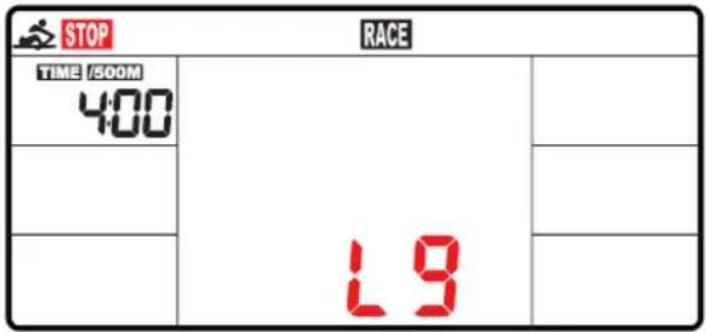
Fig. 5
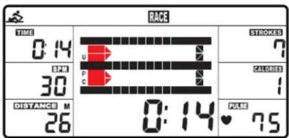
Fig. 6
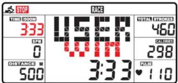
Fig. 7
A. Press START button to start and STOP will disappear. USER and PC will display in the matrix (Fig.6). The console will stop when either user or console has reached the race distance that was set. Then the matrix displays "PC WIN" or "USER WIN" (Fig.7).
B. When the race is over, you can press START to start a race once again. Press RESET to leave the RACE screen.
- RECOVERY: This is a measurement of how quickly your heart rate can return from a high (exercising) BPM to a normal BPM. This meter works with a 5.3 KHz chest strap heart rate monitor (not included). After exercising for a period of time, keep wearing chest strap monitor and press “RECOVERY” button. All function displays will stop except “TIME” starts counting down from 00:60 to 00:00. Screen will display your heart rate recovery status with the F1, F2....to F6. F1 is outstanding. F6 is poor. User may keep exercising to improve the heart rate recovery status. (Press the RECOVERY button again to return the main display.)
ALARM: Alarm only works while the console is in sleep mode. Alarm will not sound during exercise. Press and hold RESET to go to clock screen to set up ALARM.
SLEEP MODE:
The console will go into sleep mode after about 4 minutes of inactivity.
BATTERIES:
This console uses 2 AA batteries, which are included. Changing the batteries will reset all values. If there is a problem with the display, try changing the batteries first. When changing the batteries, change both of them. Do not mix battery types. Do not mix old and new batteries. Dispose of old batteries according to your regional guidelines
Trouble Shooting
| Problem | Cause | Solution |
| Monitor does not display | Batteries not Installed Install Batteries | |
| Computer Wires not connected | Ensure the computer wires are connected properly at both ends of the console support tube | |
| No speed or distance displays on the monitor | Sensor wire not connected | Ensure the computer wires are connected properly at both ends of the console support tube |
| Sensor wire not working properly Replace sensor wire | ||
| Monitor not working properly Replace monitor | ||
| No tension | Air Damper needs Adjustment | Adjust tension lever accordingly |
| Squealing Belt slipping Adjust belt | ||
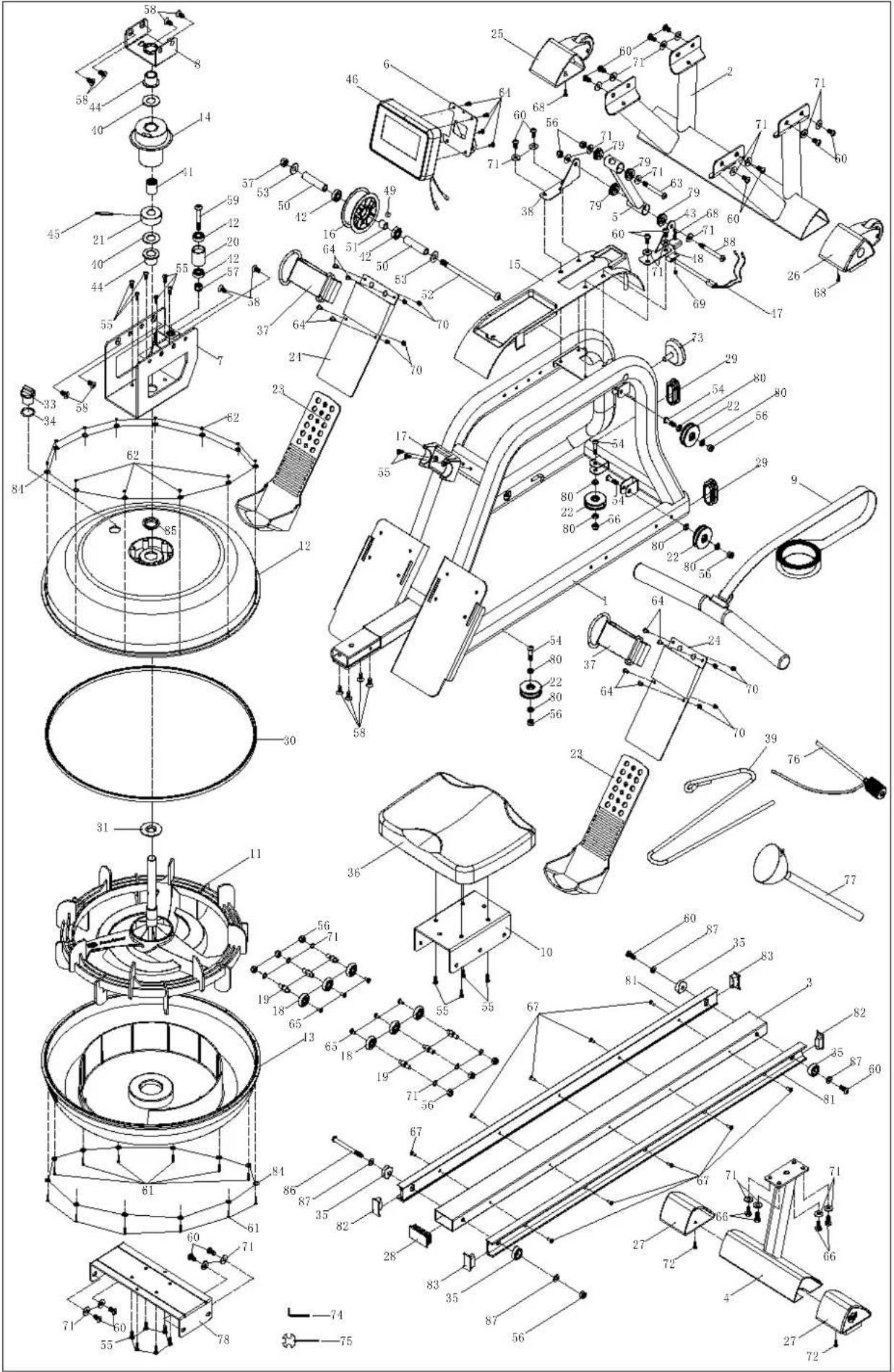
Part List
| PART NO. | DESCRIPTION | QTY |
| 1 Main frame 1 | ||
| 2 | Front Stabilizer | 1 |
| 3 Slide Rail 1 | ||
| 4 Rear Stabilizer 1 | ||
| 5 Support for computer 1 | ||
| 6 Support Plate 1 | ||
| 7 | Tank Plate | 1 |
| 8 Plate for bushing 1 | ||
| 9 Handlebar 1 | ||
| 10 Seat carriage 1 | ||
| 11 Impeller 1 | ||
| 12 | Upper tank | 1 |
| 13 Lower tank 1 | ||
| 14 Mesh belt wheel 1 | ||
| 15 Decorate cover | 1 | |
| 16 Belt wheel 1 | ||
| 17 | Handlebar seat | 1 |
| 18 Roller | 6 | |
| 19 Roller shaft | 6 | |
| 20 Guide roller | 1 | |
| 21 Magnet Seat | 1 | |
| 22 | Bungee Pulley | 4 |
| 23 Top Pedal | 2 | |
| 24 Under Pedal | 2 | |
| 25 Left End Cap | 1 | |
| 26 Right End Cap | 1 | |
| 27 | Adjustable End Cap | 2 |
| 28 Rail End Cap | 1 | |
| 29 Oval Plug | 2 | |
| 30 Rubber sealing ring | 1 | |
| 31 Impeller Shaft Seal | 1 | |
| 33 | Fill Plug | 1 |
| 34 O shape ring | 1 | |
| 35 Stopper | 4 | |
| 36 | Seat | 1 |
| 37 Pedal Straps | 2 | |
| 38 | Sensor stand L | 1 |
| 39 Bungee cord | 1 | |
| 40 Plastic washer | 2 | |
| 41 One way bearing 1 | ||
| 42 Bearing | 4 | |
| 43 | Sensor stand R | 1 |
| 44 Bushing | 2 | |
| 45 | Pin ∅6.0*40 | 1 |
| 46 | Console | 1 |
| 47 Sensor Wire 2 | ||
| 48 | Sensor Holder | 1 |
| 49 | Magnet ∅10*5 | 1 |
| 50 Spacer for mesh belt wheel 2 | ||
| 51 | Short spacer | 1 |
| 52 | Screw M10*185 | 1 |
| 53 | Washer OD25*ID10.5*2.0 | 2 |
| 54 Screw M8*30 4 | ||
| 55 | Screw M6*15 | 18 |
| 56 | Nylon lock nut M8 | 13 |
| 57 Nylon lock nut M10 2 | ||
| 58 | Flat screw M8*15 | 12 |
| 59 | Screw M10*55 | 1 |
| 60 Screw M8*18 18 | ||
| 61 | Screw M3*20 | 12 |
| 62 | Nylon lock nut M3 | 12 |
| 63 | Screw M8*70 | 1 |
| 64 | Screw M5*12 | 12 |
| 65 | Screw M5*8 | 6 |
| 66 | Outer hex screw M8*15 | 4 |
| 67 | Flat cross screw M5*15 | 10 |
| 68 | Cross Screw M4*12 | 3 |
| 69 | Nylon lock nut M4 | 1 |
| 70 Nylon lock nut M5 8 | ||
| 71 | Washer OD20*ID8.5*1.5 | 30 |
| 72 | Screw ST4.2*16 | 2 |
| 73 | Knob | 1 |
| 74 Allen wrench S5 1 | ||
| 75 | Spanner S13-S17 | 1 |
| 76 | Pumping siphon | 1 |
| 77 Funnel 1 | ||
| 78 | Lower tank plate | 1 |
| 79 | Plastic Bushing | 4 |
| 80 Spacer 8 | ||
| 81 | Aluminum | 2 |
| 82 | Rail endcap L | 2 |
| 83 | Rail endcap R | 2 |
| 84 | Stainless Washer M3 | 24 |
| 85 | Sealing ring for upper tank | 1 |
| 86 | Screw M8*90 | 1 |
| 87 | Washer OD16*ID8.5*1.5 | 4 |
| 88 | Screw M8*75 | 1 |
BOYLES BFE FITNESS EQUIPMENT
York Fitness WR1000 Water Resistance Rower.:
WARRANTY, SAFETY AND
IMPORTANT
ASSEMBLY INFORMATION
Please read and retain this manual as it will assist with identification for parts and service.
BOYLES FITNESS warrants their Rower to be free from defects in material and workmanship under normal use and service conditions.
The various components of the Rower are warranted against defects and workmanship for the time periods specified as follows:
YRK56041A
Domestic use
Lifetime frame & 1 year on all other parts
All warranty coverage extends only to the original retail purchaser from the date of purchase. BOYLES FITNESS' obligation under this Warranty is limited to replacing or repairing, at BOYLES' option, the product or parts therein. Any enquiries relating to warranties or spare parts must be directed to Spares at www.bfe.com.au/service.
For efficient processing of your enquiry, please have relevant date and proof of purchase, retailer name where you purchased the item and the brand on the product. This warranty does not extend to any damage to a product caused by abuse, improper or abnormal usage (as detailed in this instruction manual), or repairs not provided by BOYLES. Nor does this warranty extend to products used for commercial or rental purposes. This warranty does not cover ordinary wear, tear and weathering, failure to follow directions, improper installation, improper maintenance or acts of God (such as damage caused by storms, lightening and by snow or ice). No other Warranty beyond that specifically set forth above is authorised by BOYLES. Our Spares and Service Centre has been set up to provide assembly assistance, replacement parts and accessories, and to efficiently handle all warranty related matters.
Hours 8:00am – 3:00pm Mon-Fri (excluding public holidays)
Email spares@bfe.com.au W: www.bfe.com.au/service
Website: www.yorkfitness.com.au
BFE Warranty Policy – November 1 ^st 2013
- When purchased from an authorised BFE distributor, the BFE warranty shall guarantee that all framework and components of your product are free from faulty manufacture. All faulty framework and components will be repaired or replaced as set out in this policy. All warranties in this policy apply to INDOOR HOME/DOMESTIC USE ONLY.
- These warranties do not apply to products used in commercial use or applications.
- Warranty DOES NOT cover normal wear & tear and excludes faults due to misuse, abuse, incorrect assembly or lack of general maintenance.
-
Warranty is applicable to products sold and placed within Australia only.
-
IMPORTANT. Most of BFE products are tested prior to sale and we have inspectors checking all products prior to shipment. The number one reason for the occurrence of a fault is due to INCORRECT ASSEMBLY.
If you do experience any product issues, please go back to the start and double check your assembly, paying special attention to all WIRING connections. If you find that you have accidentally cut or damaged the wiring, please let us know and we will be happy to send you a new set at no-charge. If you have done this, confident you have double checked your assembly and are still experiencing problems, please visit our website to lodge a Service Request at www.bfe.com.au/service. Here you will be able to provide your best contact details, proof of purchase, serial number and a brief explanation of what has occurred. This is the quickest and most reliable way to get your Service Request processed. Once we have your details, you will receive an email confirmation your ticket has been lodged.
Once we complete a round of preliminary questions and assess the details, we may send you a replacement part, and talk you through how to fit it over the phone. If it is deemed by our Service Manager that it is too difficult, we can arrange (where available) a service technician to visit with you.
NOTE. If we arrange for a service technician (where applicable) and it is found that it is not a manufactures fault and found to be an assembly issue, normal wear and tear, transport damage or misuse, there will be a call out fee of \$140 depending on location.
(Surcharge will apply for non-metro areas)
Warranty commences from the date of purchase from the retail store. Warranty only applies to the original purchaser and is NON transferable. Warranty is void if the serial number of the product has been removed or tampered with.
Warranty does not apply to defects, faults or failures due to:
(a) Defects caused during assembly or failure to assemble to the assembly manual provided. Assembly errors include but are not limited to damaged wiring harness, stripped crank arms and or pedals and bolts used in the wrong locations.
(b) Lack of general maintenance and or failure to service or maintain the equipment in accordance with the user manual specifications and recommendations. This includes a lack of lubrication. Only use factory approved silicon lubricant. DO NOT USE WD40 or anything similar. You can purchase silicon lubricant liquid from your retailer, or contact us directly at sales@bfe.com.au.
(c) Power Surges. The computers, control boards and motors are very sensitive to power fluctuations. You must use a surge protector on all items that plug into your mains power otherwise your electronics will not be covered by this warranty. You can purchase these from numerous retailers or you can contact us at www.bfe.com.au/service to get a price from our Spares and Service team.
(d) User negligence, abnormal or excessive use, misuse, abuse or transport damage.
(e) Repairs, alterations or modifications by NON BFE authorised service technician.
(f) Accident, fire, flood or malicious damage by third person.
(g) Ordinary wear and tear.
(h) Failure to keep the product in a clean, dry environment causing rust. Your equipment must be stored indoors. You should also wipe off any sweat or moisture after each training session.
(i) A ny products sold or placed in an application or the incorrect environment that is not recommended by BFE or as not stipulated in the owner's manual such as a commercial / rental environment will void the warranty set forth by BFE
(j) BFE recommends the use of a protective rubber floor mat. This reduces the incidence of dust and lint collection around the motor, reduces noise & protects your floor. You can purchase this from your retailer or contact BFE directly on 02 4648 0800.
(k) BFE will have the option to repair or replace any product which requires attention under the warranty.
NOTE: Lifetime* refers to the warranty coverage of the unit's service life expectancy, NOT the lifetime of the purchaser.
Servicing/Spare Parts- As with any mechanical equipment, general maintenance should be performed on a regular basis by an authorised retailer or service technician. This will ensure longevity of the product and ensure that it is kept working in optimum condition. Failure to properly maintain your equipment may lead to safety issues and may also void the warranty.
You should only use genuine BFE replacement parts otherwise the warranty will be void.
Freight Costs:
The cost of freighting the replacement part under warranty to the customer shall be free of charge. Your requirement is to return the faulty part via the pre-paid postal service which we will supply.
Returned Goods:
The unauthorised return of parts or product shall be refused and placed in the hands of the carrier at the cost of the shipper. Return authorisations (RA) can be obtained from BFE Head Office only.
Service Department hours: Monday to Friday between 8am and 3pm
Service Email: spares@bfe.com.au
Service Request: www.bfe.com.au/service
PLEASE NOTE: Authorised service technicians do not reside in all areas of this vast country. If you live beyond the reasonable service area of a metropolitan area, BFE may not be able to support the labour portion of the product warranty. Alternatively, you can return (at your cost) your product to the closest BFE repair centre, where it will be fixed at no charge under the warranty period.
(Metropolitan Area - defined as no more that 50km from G.P.O in all capital cities)
Disclaimer:
Our goods come with guarantees that cannot be excluded under the Australian Consumer Law. You are entitled to a replacement or refund for a ‘Major Failure’ and for compensation for any other reasonable foreseeable loss or damage.
You are also entitled to have goods repaired or replaced if the goods fail to be of an acceptable quality and the failure does not amount to a 'Major Failure'.
BFE does not assume, nor authorise any representative or other person to make or assume any warranties whatsoever on behalf of BFE, whether expressed or implied, in connection with the sale, service, or shipment of our products.
BFE reserve the right to make changes and improvements in our products and specifications without incurring any obligation to similarly alter products previously purchased.
This warranty operates in addition to other rights and remedies available to consumer's rights under the Australian Consumer Law.
Service Department hours: Monday to Friday between 8am and 3pm
Email: spares@bfe.com.au W:www.bfe.com.au/service
- ATTENTION
- Important Safety Instructions
- Fitness Equipment Safety Instructions
- SAVE THESE INSTRUCTIONS - SAFETY FIRST!
- Before you begin
- PRE-ASSEMBLY CHECK LIST
- Parts List
- HARDWARE PARTS LIST
- Stopper 2pcs
- M8*15 4pcs
- M8*18 14pcs
- M8*15 4pcs
- M4*12 2pcs
- OD20*ID8.5*1.5 16pcs
- S5 1pc
- S13-17 1pc
- Rail EndcapL 1pc
- RailEndcapR 1pc
- OD16*ID8.5*1.5 2pcs
- Assembly Instructions
- Rear Stabilizer
- Front Stabilizer End caps
- Attaching the Front Stabilizer
- Seat and Rail
- Console
- How to Fill and Empty the Tank
- NOTE:
- WATER LEVEL
- Adjustment Guide
- Adjustment Guide and Storage
- Adjusting the Balance
- CAUTION!
- Operation of Your Console
- Button Functions
- Functions
- MANUAL (Fig.4): There are 2 options in MANUAL mode.
- SLEEP MODE:
- BATTERIES:
- BOYLES BFE FITNESS EQUIPMENT
- BFE Warranty Policy – November 1 st 2013
- Freight Costs:
- Returned Goods:
- Service Department hours: Monday to Friday between 8am and 3pm
- Disclaimer:
Brand : York Fitness
Model : WR1000
Category : Rowing Machine