Diamond R301 - Rowing Machine York Fitness - Free user manual and instructions
Find the device manual for free Diamond R301 York Fitness in PDF.


| Product Type | Rowing Machine |
| Brand | York Fitness |
| Model | Diamond R301 |
| Max User Weight | 120 kg (264 lbs) |
| Resistance System | Magnetic, computer-controlled |
| Resistance Levels | 16 (1 = easy, 16 = hard) |
| Display Type | LCD Console |
| Display Parameters | Time, Distance, Calories, Stroke Count (COUNT), SPM, RPM, Speed (SPD), Pulse, 500m Time, Power, ODO |
| Workout Programs | Manual (P1), Aerobic (P2), Interval (P3), Cardio (P4), Variation (P5), To The Max (P6), HRC 60% (P7), HRC 85% (P8) |
| Heart Rate Control | Yes, compatible with chest strap (not included); P7 at 60% max HR, P8 at 85% max HR |
| Power Supply | 4 x AA batteries (1.5V) |
| Foldable for Storage | Yes |
| Seat | Sliding seat on rail with carriage |
| Pedals | Adjustable with straps |
| Handlebar | Pulling handlebar with chain drive |
| Frame Material | Steel |
| Safety Standard | EN957 Class HC |
| Warranty | 12 months parts and labor (home use) |
| Assembly Required | Yes, with included tools |
| Cleaning | Warm damp cloth; no solvents |
| Storage | Indoor, dry place |
Frequently Asked Questions - Diamond R301 York Fitness
User questions about Diamond R301 York Fitness
0 question about this device. Answer the ones you know or ask your own.
Ask a new question about this device
Download the instructions for your Rowing Machine in PDF format for free! Find your manual Diamond R301 - York Fitness and take your electronic device back in hand. On this page are published all the documents necessary for the use of your device. Diamond R301 by York Fitness.
USER MANUAL Diamond R301 York Fitness
natural_image
Line drawing of a YORK fitness magair row exercise machine (no text or symbols on the device itself)07/30/2009
SAFETY INFORMATION
SAFETY PRECAUTIONS
Before using the equipment, please ensure that you read the safety precautions described below. Always ensure that the equipment is operating correctly.
The safety precautions noted below are intended to instruct you in the safe and correct operation of the equipment to prevent injuries or damage to yourself, other persons and equipment.
THIS LIST IS NOT EXHAUSTIVE / SAVE THESE INSTRUCTIONS
DISCLAIMER
While every effort has been made to ensure that the information contained in this guide is accurate and complete, no liability can be accepted for any errors or omissions. York Fitness reserves the right to change the specifications of the hardware and software described herein at any time without prior notice.
No part of this guide may be reproduced, transmitted, transcribed, stored in a retrieval system, or translated into any language in any form, by any means, without the prior written permission of York Fitness.
York Fitness makes no warranties for damages due to mistaken operation or malfunction of the equipment.
EQUIPMENT SAFETY:
YOUR PRODUCT IS INTENDED FOR USE IN CLEAN DRY CONDITIONS. YOU SHOULD AVOID STORAGE IN EXCESSIVELY COLD OR DAMP PLACES AS THIS MAY LEAD TO CORROSION AND OTHER RELATED PROBLEMS THAT ARE OUTSIDE OUR CONTROL. FOR INDOOR USE ONLY.
THIS PRODUCT IS NOT SUITABLE FOR THERAPEUTIC PURPOSES.
Please keep all children away from exercise • products when in use. Do not allow children to climb or play on them when they are not in use.
Regularly check to see that all nuts, bolts and • fittings are securely tightened. Periodically check all moving parts for obvious signs of wear or damage. The safety level of this equipment can only be maintained only if it is regularly examined for wear and tear.
Replace defective components immediately. If you are in any doubt, do not use your product. Contact CUSTOMER SUPPORT.
Clean only with a damp cloth. Do not use solvent • cleaners.
Before use, always ensure that your product is • positioned on a solid, flat surface. If necessary, use a rubber mat underneath to reduce the possibility of slippage during use.
Always ensure that the equipment has adequate • space one each side and front.
Use this appliance only for its intended use as • described in this manual. Do not use attachments not recommended by the manufacturer.
Always check that any pins / fixings are tight and secure before use and / or after adjustment.
Never leave any adjustment devices projecting from the product.
FITNESS PRECAUTIONS:
Before you undertake any programme of exercise that will increase cardiovascular activity, please be sure to consult with your doctor. Frequent strenuous exercise should be approved by your doctor and proper use of your product is essential.
If you feel any pain or abnormal symptoms, STOP YOUR WORKOUT IMMEDIATELY. Consult your physician immediately.
EXERCISE SAFETY:
Wear proper workout clothing: Do not wear loose • clothing.
Do not wear shoes with leather soles or high heels. • Tie all long hair back.
Remove all personal jewelry before exercising.
After eating, allow 1-2 hours before exercising as this will help to prevent muscle strain.
Injuries may result from incorrect or excessive training.
MAX. USER WEIGHT: 120KG
SAFETY STANDARDS
This equipment meets the requirements of the EU's EMC and Low Voltage directives (where applicable), AS4092, EN957 parts 1 and 7 - CLASS HC. Therefore the product carries the following marks:


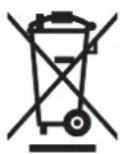
PROTECT THE ENVIRONMENT BY NOT DISPOSING OF THIS PRODUCT OR BATTERIES WITH HOUSEHOLD WASTE. CHECK YOUR LOCAL AUTHORITY FOR RECYCLING ADVICE AND FACILITIES.
CUSTOMER SUPPORT
CONTACT INFORMATION
York Fitness U.K. Ltd. (England)
York Way, Daventry, Northants, NN11 4YB, England
Tel: (01327) 701800
Help desk Tel: (01327) 701824
Fax: (01327) 706704
Email: helpdesk@yorkfitness.co.uk
York Fitness (Australia) Pty. Ltd.
Unit 1, Lot 2, Swaffham Road, Minto, N.S.W. 2566,
Australia
Tel: (02) 9603 8444
Help desk Tel: 1800 730 149
Fax: (02) 9603 8555
Email: service@yorkfitness.com.au
PLEASE RETAIN
We suggest you record the serial, original purchase date, and place of purchase below:
Serial no.
- This can be found on the sticker located as indicated.
Original purchase date.
Place of purchase.
Should you require any assistance regarding this product please gather the following information.
Information about the place and conditions of use.
Precise description of the issue / defect.
IT IS ALSO IMPORTANT TO KEEP YOUR RECEIPT AS PROOF OF DATE OF PURCHASE.
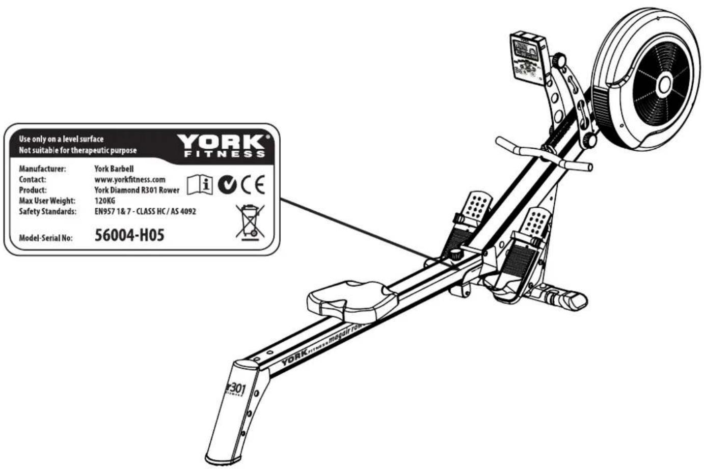
TABLE OF CONTENTS
Thank you for choosing
YORK® FITNESS
You have chosen a high quality, safe and innovative piece of equipment as your training partner and we are certain it will keep you motivated on the way to achieving your personal fitness goal.
The precautions noted within this guide are intended to instruct you in the safe and correct use of the products and to prevent injuries or damage to yourself, other persons and property. Please read and ensure that you understand them before proceeding to other sections of this guide.
natural_image
Black-and-white photo of a woman holding a bottled water bottle, wearing a white top with a towel (no text or symbols visible)TABLE OF CONTENTS
Safety Information 02
Safety Precautions • 02
- Disclaimer 02
Equipment Safety • 02
Fitness Precautions • 02
• Exercise Safety 02
• Max. User Weight 02
• Safety Standards 02
Customer Support 03
- Contact Information 03
Table Of Contents 04
Assembly Instructions 05 - 11
• Getting Started 05
• Hardware Identification Chart 05
• Assembly Instructions 06 - 10
- Final Check 11
• Battery Replacement Instructions .... 11
Operation Instructions 12 - 15
- Console Display And Feedback 12
- Button Functions 12
• Using Workout Programs 13 - 14
• Storage 14
- Cleaning 14
- Maintenance 14
- Troubleshooting 14
• Adjusting The Resistance 15
- Fold For Storage 15
• Unfold For Use 15
Fitness Guide 16 - 17
• Exercising With Your Rower 16
• How To Row 16
• Conditioning Guidelines 17
• Target Heart Rate Zone Estimated By Age ..... 17
Warranty 18
Part List 19
Exploded Drawing 20 - 21
ASSEMBLY INSTRUCTIONS
GETTING STARTED
Place all parts from the box in a cleared area and position them on the floor in front of you. Remove all packing materials from your area and place them back into the box. Do not dispose of the packing materials until assembly is completed. Read each step carefully before beginning. If you are missing a part, please contact our technical support.
After unpacking the unit, open the hardware bag and make sure that you have all the following items. Some hardware may be already attached to the part.
 | Part No. 60 x 245MM CARRIAGE BOLT |
 | Part No. 35 x 10FLAT WASHER |
 | Part No. 12 x 2NYLOCK NUT |
 | Part No. 11 x 2PLASTIC BOLT CAP |
 | Part No. 47 x 620MM ALLEN HEAD BOLT |
| [BHTG] | Part No. 9 x 2SPRING WASHER |
 | Part No. 48 x 1HAND WHEEL KNOB |
 | Part No. 49 x 1LARGE FLAT WASHER |
 | Part No. 51 x 255MM CARRIAGE BOLT |
| [SYYH] | Part No. 36 x 2NYLOCK CAP NUT |
 | Part No. 33 x 4PLASTIC SPACER |
natural_image
Two technical line drawings of tools: a bent bracket and a pin-like tool (no text or symbols)HARDWARE IDENTIFICATION CHART
This chart is provided to help identify the hardware used in the assembly process. Place the washers, the end of the bolts, or screws on the circles to check for the correct diameter. Use the small scale to check the length of the bolts and screws.
NOTE: THE LENGTH OF ALL BOLTS AND SCREWS EXCEPT THOSE WITH FLAT HEADS IS MEASURED FROM BELOW THE HEAD TO THE END OF THE BOLT OR SCREW. FLAT HEAD BOLTS AND SCREWS ARE MEASURED FROM THE TOP OF THE HEAD TO THE END OF THE BOLT OR SCREW.
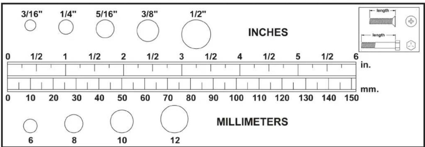
other
| Millimeter | Diameter (inches) | | ---------- | ----------------- | | 6 | 3/16" | | 8 | 1/4" | | 10 | 5/16" | | 12 | 3/8" | | 120 | 1/2" |ASSEMBLY INSTRUCTIONS
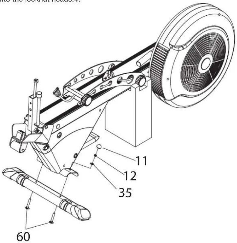
STEP 1
Keep the poly-foam block as packed on the front 1. end of main frame when you remove it from the carton, it will keep the main frame stable and avoid damage during the assembly procedure.
Stand the main frame on the floor carefully as 2. shown.
Fix the front stabilizer to the main frame and 3. secure, using 2 x carriage bolts, washers and nylon locknuts as shown.
Fix the plastic nut caps onto the locknut heads.4.
| Part No. 11 x 2PLASTIC BOLT CAP | |
| Part No. 12 x 2NYLOCK NUT | |
| Part No. 35 x 2FLAT WASHER | |
| Part No. 60 x 245MM CARRIAGE BOLT |
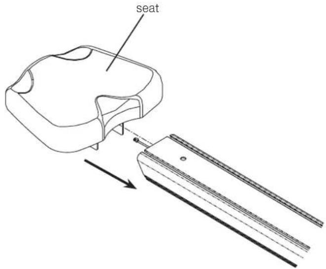
STEP 2
Slide the seat with carriage assembly onto the 1. rower track carefully as shown.
ASSEMBLY INSTRUCTIONS
STEP 3
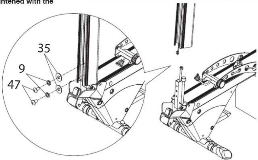
Ask someone to help you hold the seat carriage 1. out of the way, and connect the computer wires as shown - make sure it is fully connected.
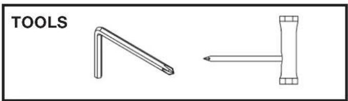
Slide the seat track over the mounting support 2. carefully and secure in position by using 2 x allen head bolts, spring washers and flat washers. Ensure the computer wires do not get trapped. Make sure the bolts are fully tightened with the allen key.
 | Part No. 47 x 220MM ALLEN HEAD BOLT |
| [8CBD] | Part No. 9 x 2SPRING WASHER |
 | Part No. 35 x 2FLAT WASHER |
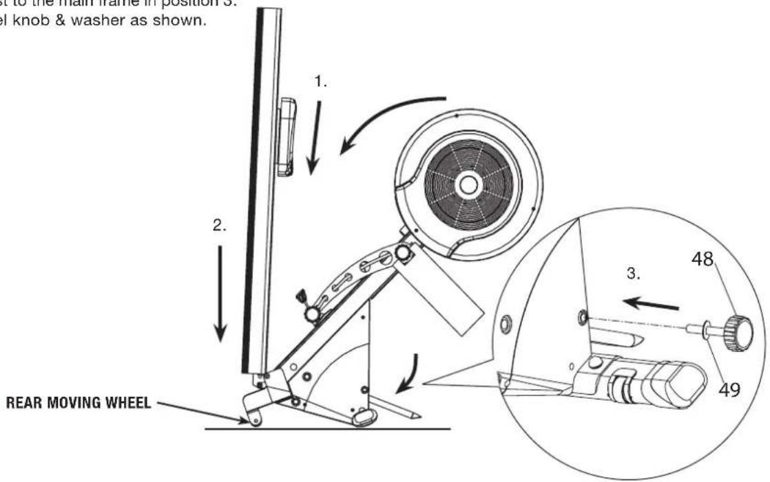
STEP 4
Slide the seat carriage downwards to the end stop.1.
Carefully hold and push the seat track downwards 2. until the rear moving wheel stands on the floor. This folds the rower to stand stably on the floor.
Secure the front post to the main frame in position 3. with the hand wheel knob & washer as shown.
 | Part No. 48 x 1HAND WHEEL KNOB | |
 | Part No. 49 x 1LARGE FLAT WASHER |
ASSEMBLY INSTRUCTIONS
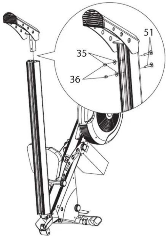
STEP 5
Ask someone to help you hold the seat track still.1.
Slide the rear stabilizer onto the seat track carefully 2. and secure in position by using 2 x carriage bolts, flat washers and nyloc cap nuts as shown. Make sure the bolts are fully tightened with the nut driver tool.
 | Part No. 51 x 255MM CARRIAGE BOLT |
 | Part No. 35 x 2FLAT WASHER |
| [52KB] | Part No. 36 x 2NYLOCK CAP NUT |
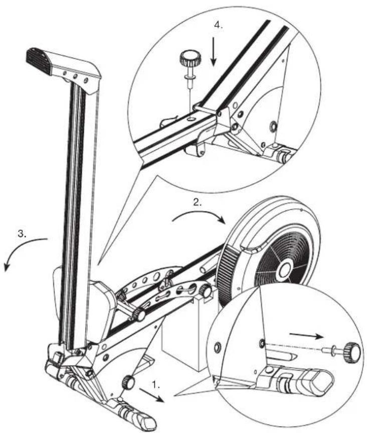
STEP 6
Remove the hand wheel knob & washer from the 1. main frame carefully as shown.
Hold the whole rower with two hands and fold it 2. towards floor until the poly-foam block stands on floor stably.
Hold the seat track and fold it towards floor until the 3. rear stabilizer stands on floor stably.
Fasten the hand wheel knob with washer to the seat 4. track securely.
ASSEMBLY INSTRUCTIONS
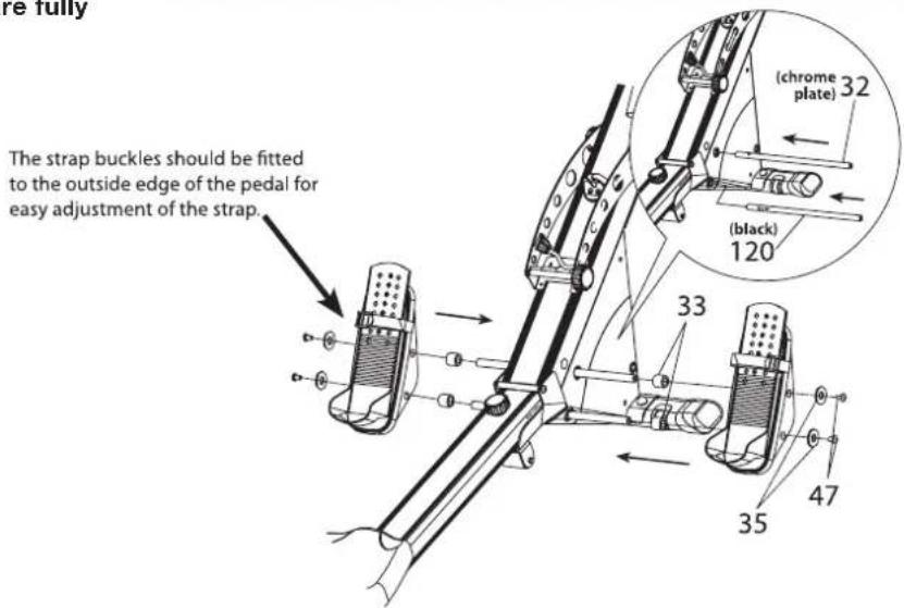
STEP 7
Slide the pedal pivot rods through the main frame 1. holes until an equal amount of the rods protrude from each side.
Slide the spacers and pedal assemblies onto the 2. pivot rods from both ends and secure, using 4 x allen head bolts and washers as shown. Make sure the two different pivot rods are fitted in the same order as shown in the diagram and bolts are fully tightened with allen key.
 | Part No. 47 x 420MM ALLEN HEAD BOLT |
 | Part No. 35 x 4FLAT WASHER |
 | Part No. 33 x 4PLASTIC SPACER |
STEP 8
Remove the poly-foam block attached underneath 1. the front end of the main frame.
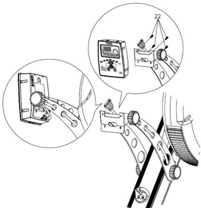
Loosen the hand wheel knobs and rotate the 2. console fixing plates to the required view angle.
Re-tighten the hand wheel knobs to fix the plates in 3. position.
Insert 4 x batteries (AA size 1.5V) into the 4. compartment in the back of the computer console. (See page 11 for batteries replacement instructions)
Attach the computer console onto the fixing bracket 5. and secure, using 4 x machine screws as shown. (The machine screws are located in the back of the computer console.
Plug the computer wire into the socket on the back 6. of the computer through the fixing bracket - make sure it's fully connected.
ASSEMBLY INSTRUCTIONS
STEP 9
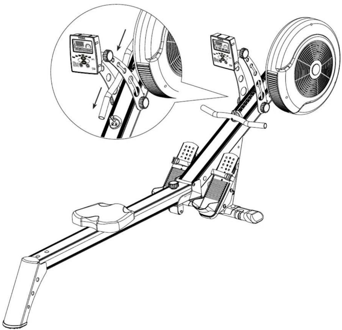
Pull and slide the handlebar and pass through the 1. console fixing plates carefully as shown.
Rotate the handlebar and rest onto the handlebar 2. holder in position.
natural_image
Technical line drawing of a stationary exercise machine with attached digital display and control panel (no text or symbols)ASSEMBLY INSTRUCTIONS
FINAL CHECK
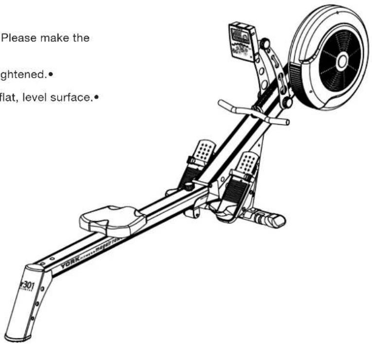
Your R301 Rower is now assembled. Please make the following final checks:
Make sure all screws / bolts are tightened.
Make sure the equipment is on a flat, level surface.
natural_image
Close-up of a hand pressing a small black component on a device (no visible text or symbols)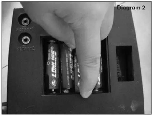
natural_image
Close-up of a hand inserting batteries into a device casing, labeled 'Diagram 2' (no text on main subject)BATTERY REPLACEMENT INSTRUCTIONS:
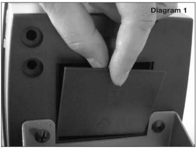
Open the battery compartment cover (Diagram 1).1.
Remove battery by pulling the battery in direction of 2. spring and lift opposite end upwards (Diagram 2).
Insert 4 AA batteries ensuring you match the 3. polarity markings (+ and -) on the batteries with the indicators in the battery compartment. Push flat end (-) against spring and when clear push other end into holder.
Close the battery compartment.4.
TIPS & WARNINGS
Always change all batteries at the same time.
Always use the same type of batteries.
Never recharge Alkaline AA batteries.
Do not try to heat, ignite, disassemble or throw AA • batteries into a fire.
Do not leave old batteries in the console, and remove batteries from the console if you won't be using it for a long time.
PROTECT THE ENVIRONMENT BY NOT DISPOSING OF THIS PRODUCT OR BATTERIES WITH HOUSEHOLD WASTE. CHECK WITH YOUR LOCAL AUTHORITY FOR RECYCLING ADVISE AND FACILITIES.
* PICTURE MAY VARY FROM ACTUAL MODEL.
OPERATION INSTRUCTIONS
CONSOLE DISPLAY AND FEEDBACK
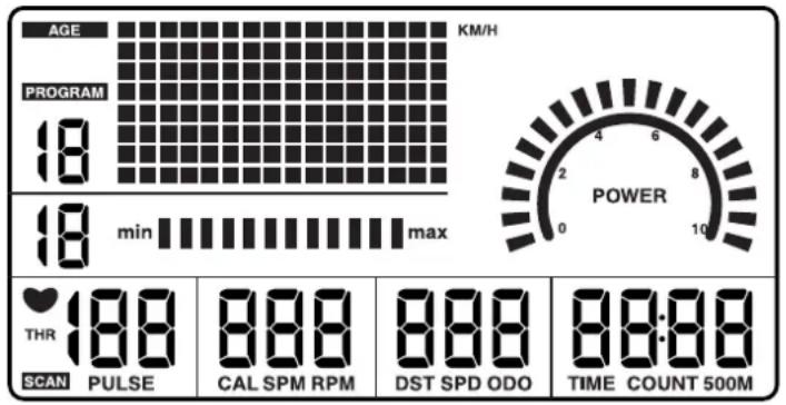
| DISPLAY DESCRIPTION | |
| AGE | The user age has been set. |
| PROGRAM | The number of the selected pre-set program (P1 - P8). |
| MIN. ~ MAX. | Displays the resistance level in manual mode. |
| THR | Target heart rate frequency has been set. |
| SCAN | Automatically scans through the feedback modes, each being displayed for 5 seconds. |
| PULSE | Current heart rate in beats per minute (bpm) (Only displayed when the transmitter chest strap is used.) |
| CAL | Approximate calories burned this session (For comparison only, not to be used for medical purposes); default counts up from zero, but counts down if a target has been set. |
| SPM | The strokes per minute (SPM) you are rowing at. |
| RPM | The revolutions per minute (RPM) you are rowing at. |
| DST | Distance travelled this session; default counts up from zero, but counts down if a target has been set. |
| SPD | The current speed you are rowing at, in km/h. |
| ODO | Total distance travelled since last battery changed. |
| TIME | Time exercised this session; default counts up from zero, but counts down if a target has been set. |
| COUNT | Stroke exercised this session; default counts up from zero, but counts down if a target has been set. |
| 500M | Expected exercise time for 500 metres travelled. |
| POWER | The force of each rowing stroke. |
BUTTON FUNCTIONS
| BUTTON PRE-WORKOUT DURING WORKOUT | ||
| DISPLAY MODE | Switch different mode values. Select display mode. | |
| PROGRAM | To select a program (P1 - P8). | |
| SET | Confirm current target values setting. | |
| RESET | Reset current setting value, hold for total reset. | |
| + | Increase values setting in “Target Setting” mode. Increase the resistance level. | |
| TIMER: | Decrease values setting in “Target Setting” mode. Decrease the resistance level. | |
OPERATION INSTRUCTIONS
USING WORKOUT PROGRAMS
When you turn the power on it will enter the main display mode, waiting for you to select a program and begin your workout.
| DISPLAY DESCRIPTION | |
| QUICK START | Press the “Display Mode” button to activate the computer console.1.Begin rowing.2.Adjust the resistance level with the “+/-” keys.3.The values of time, distance, calories, count, will start counting upwards.4. |
| MANUAL MODE | In manual mode, the user is free to adjust the resistance level at any point throughout the workout.Press “Program” button to choose your program (P1)1.Press “Set” button to confirm the “Manual” selection.2.Start rowing to begin your workout. 3.NOTE: You can also add to your program targets based on time, distance, calories, stroke or pulse rate. To do this, see the “Target Program” instruction. |
| PROGRAM MODE | There are 5 pre-set programs available for you to choose from. The resistance level adjusts automatically throughout the programs.Press “Program” button to choose your program (P2 - P6).1.Press “Set” button to confirm your selection.2.Press “Display Mode” button to enter the “Time” mode.3.The value of “00:00” will be flashing in the “Time” window.4.Press “+” or “-” button to set your workout time.5.6. Press “Set” to confirm your setting.7. Start rowing to begin your workout.NOTE: Your can change the resistance level at any point during the workout and the rest of the segments will be adjusted by scale automatically.NOTE: You can also add to your program targets based on time, distance, calories, stroke or pulse rate. To do this, see the “Target Program” instruction.NOTE: Each program is made of 16 segments and the length of each segment will depend on the time you set for your workout. |
| HRC (HEART RATE CONTROL) | HRC program works by automatically adjusting the resistance to keep you working out at your target heart rate. To do this, the console will need your pulse reading throughout the exercise, which it gets from you wearing a chest strap transmitter.If your heart rate is too high, the resistance will decrease.If your heart rate is too low, the resistance will increase.This console features 2 heart rate control programs:60% - Target to operate at 60% of your maximum heart rate.85% - Target to operate at 80% of your maximum heart rate.Press and hold “Display Mode” button for 5 seconds to enter the “Age” mode.Press “+” or “-” button to set your age.Press “Display Mode” to confirm your setting.Press “Program” button to choose your program (P7 - 60% Maximum Heart Rate / P8 - 85% Maximum Heart Rate)Press “Set” button to confirm your selection.The value of “THR” will be flashing in the “Pulse” window.Press “Set” to confirm your target heart rate setting.Start rowing to begin your workout.NOTE: You can also add to your program targets based on time, distance, calories or stroke. To do this, see the “Target Program” instruction. |
Continue on next page...
OPERATION INSTRUCTIONS
... Continued from previous page
| DISPLAY DESCRIPTION | |
| TARGET PROGRAM | You can choose to workout by setting a target based on pulse rate, calories burned, distance travelled, time or the strokes rowed you want to achieve.When you reach your target the rower will sound a short alarm.Set to your desired program as described previously, but before pressing “Set” to begin your exercise.The value of “0” will be flashing in the “Pulse” window.1.Press “+” or “-” to set your Target Pulse Rate.2.Press “Set” to confirm your setting.3.The value of “0” will be flashing in the “Calories” window.4.Press “+” or “-” to set your Target Calories.5.Press “Set” to confirm your setting.6.The value of “0” will be flashing in the “Distance” window.7.Press “+” or “-” button to set your Target Distance.8.Press “Set” to confirm your setting.9.The value of “00:00” will be flashing in the “Time” window.10.Press “+” or “-” button to set your Target Time.11.Press “Set” to confirm your setting.12.The value of “0” will be flashing in the “Count” window.13.Press “+” or “-” button to set your Target Stroke.14.Press “Set” to confirm your setting.15.Start rowing to begin your workout.16.NOTE: You only have to set one of the targets described above, and once done you can press “Set” to go straight into your workout, however, if you set multiple targets the workout will end when the first target is reached. |
P1

manual
P2

aerobic
P3

interval
P4

cardio
P5

variation
P6

to the max
P7 HRC 60% max.
P8 HRC 85% max .
STORAGE
Keep the equipment in a dry place with as little temperature variation as possible. Try to protect from dust and always unplug when not in use (if applicable).
CLEANING
Use a warm, damp cloth to wipe the surfaces. Mild detergent may be used if necessary. NEVER REMOVE THE PROTECTIVE CASING.
MAINTENANCE
Ensure you regularly check components for wear and tear and make sure all the nuts and bolts are tightened before each exercise session.
TROUBLESHOOTING
IF YOU HAVE A PROBLEM WITH YOUR EQUIPMENT, BEFORE YOU DO ANYTHING ELSE PLEASE CHECK THAT ALL THE CABLES HAVE BEEN CONNECTED CORRECTLY. LOOSE CABLES ARE VERY COMMON AND MANY PROBLEMS CAN BE SOLVED BY MAKING SURE THE CABLES ARE PROPERLY CONNECTED.
IF YOU ARE STILL HAVING PROBLEMS WITH YOUR EQUIPMENT, PLEASE CONTACT OUR CUSTOMER SUPPORT.
OPERATION INSTRUCTIONS
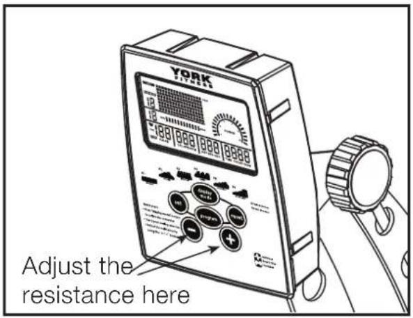
This rower features a speed independent braking (resistance) system. The resistance is controlled by a magnet, which is moved closer or further away from the fan wheel - the closer the magnet is to the fan wheel the higher the resistance. The magnet is computer controlled, to adjust simply press "+ / -" buttons on the console. The resistance levels go from 1 = easy to 16 = hard.
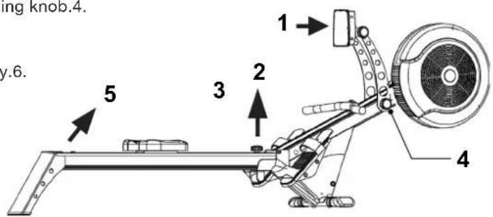
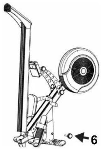
FOLD FOR STORAGE
Push computer fully back.1.
Remove hand wheel.2.
Push middle down to floor.3.
Support front by holding knob.4.
Lift up track.5.
Re-fit hand wheel fully.6.
natural_image
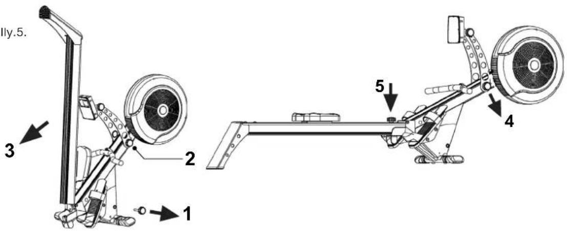
Technical line drawing of a mechanical lever system with no visible text or symbolsUNFOLD FOR USE
Remove hand wheel.1.
Support front by holding knob.2.
Carefully lower track.3.
Lower front.4.
Re-fit hand wheel fully.5.
FITNESS GUIDE
EXERCISING WITH YOUR ROWER
Rowing is an extremely effective form of exercise. It strengthens the heart, improves circulation, as well as exercising all the major muscle groups - back, waist, arms, shoulders, hips & legs.
ALWAYS CONSULT YOUR DOCTOR BEFORE UNDERTAKING A NEW EXERCISE REGIME.
IF YOU EXPERIENCE NAUSEA, DIZZINESS OR OTHER ABNORMAL SYMPTOMS DURING EXERCISE, STOP AT ONCE AND CONSULT YOUR DOCTOR.
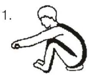
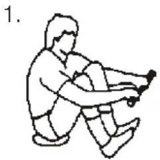
HOW TO ROW:
Take up the initial position leaning forward, knee bent and arms straight.1.
Push yourself backwards, straightening your back and legs at the same time.2.
Continue movement until you are leaning slightly backwards, bending return to Step 1 and repeat.3.
THIS PRODUCT IS COMPLIANT WITH EUROPEAN STANDARDS (EN957). THE USER MUST REMAIN AWARE THAT IF THIS PRODUCT IS NOT USED CORRECTLY THE POTENTIAL FOR INJURY REMAINS. THERE ARE MANY MOVING PARTS ON THIS PRODUCT, WHICH THE USER MUST BE AWARE OF. WHEN MOVING THE ROWER OR ADJUSTING POSITION, THE USER SHOULD PAY PARTICULAR ATTENTION THE SEAT & RUNNER ASSEMBLY.
- Please ensure that fingers are not placed inside of the runner assembly when moving the product.
- When adjusting your exercise position and you need to steady yourself by holding onto the rower, ensure that it is the underside of the seat upholstery that you are grasping.
natural_image
Simple line drawing of a person sitting and leaning forward (no text or symbols)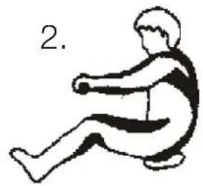
natural_image
Simple line drawing of a person sitting in a chair, no text or symbols present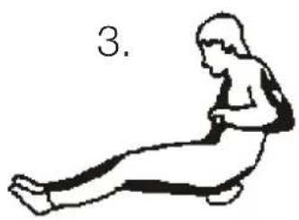
natural_image
Simple line drawing of a person sitting on their back in a seated posture (no text or symbols)ALTERNATIVE EXERCISE - LEG ONLY ROWING:
This exercise will help tone and strengthen the muscles in your legs and back. With your back straight and arms outstretched, bend your legs until the row arms are in the starting position. Use your legs to push your body back whilst keeping your arms and back straight, slowly return to start position and repeat.
natural_image
Line drawing of a person in a seated posture performing a physical exercise (no text or symbols)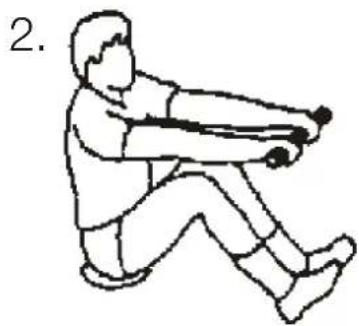
natural_image
Line drawing of a person in a seated posture holding a long object, labeled with number 2 (no text or symbols on the figure itself)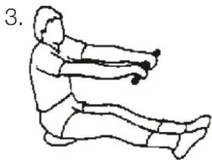
natural_image
Line drawing of a person performing a seated exercise with arms extended (no text or symbols)FITNESS GUIDE
CONDITIONING GUIDELINES:
How you begin your exercise program depends on your physical condition. If you have been inactive for several years or are out of shape, start slowly and increase your workout gradually. Increase your workout intensity gradually by monitoring your heart rate while you exercise.
Remember to follow these essentials:
Have your doctor review your training and diet programs.
- Begin your training program slowly with realistic goals that have been set by you and your physician.
Warm up before you exercise and cool down after you work out.
- Take your pulse periodically during your workout and strive to stay within a range of 60% (lower intensity) or 90% (higher intensity) of your maximum heart rate zone. Start at the lower intensity and build up to higher intensity as you become more aerobically fit.
If you feel dizzy or light-headed you should slow down or stop exercising.
Initially you may only be able to exercise within your target zone for a few minutes; however, your aerobic capacity will improve over the next six to eight weeks. It is important to pace yourself while you exercise so you don't tire too quickly.
To determine if you are working out at the correct intensity, use a heart rate monitor or use the table below. For effective aerobic exercise, your heart rate should be maintained at a level between 60% and 90% of your maximum heart rate. If just starting an exercising program, work out at the low end of your target heart rate zone. As your aerobic capacity improves, gradually increase the intensity of your workout by increasing your heart rate.
Measure your heart rate periodically during your workout by stopping the exercise but continuingly to move your legs or walk around. Place two or three fingers on your wrist and take a six second heartbeat count. Multiply the results by ten to find your heart rate. For example, if your six second heartbeat count is 14, your heart rate is 140 beats per minute. A six second count is used because your heart rate will drop rapidly when you stop exercising. Adjust the intensity of your exercise until your heart rate is at the proper level.
TARGET HEART RATE ZONE ESTIMATED BY AGE*
| AGE TARGET HEART RATE ZONE(55% - 90% OF MAXIMUM HEART RATE) | AVERAGE MAXIMUMHEART RATE 100% | |
| 20 YEARS 110-180 | BEATS PER MINUTE 200 BEATS PER MINUTE | |
| 25 YEARS 107-175 | BEATS PER MINUTE 195 BEATS PER MINUTE | |
| 30 YEARS 105-171 | BEATS PER MINUTE 190 BEATS PER MINUTE | |
| 35 YEARS 102-166 | BEATS PER MINUTE 185 BEATS PER MINUTE | |
| 40 YEARS 99-162 | BEATS PER MINUTE 180 BEATS PER MINUTE | |
| 45 YEARS 97-157 | BEATS PER MINUTE 175 BEATS PER MINUTE | |
| 50 YEARS 94-153 | BEATS PER MINUTE 170 BEATS PER MINUTE | |
| 55 YEARS 91-148 | BEATS PER MINUTE 165 BEATS PER MINUTE | |
| 60 YEARS 88-144 | BEATS PER MINUTE 160 BEATS PER MINUTE | |
| 65 YEARS 85-139 | BEATS PER MINUTE 155 BEATS PER MINUTE | |
| 70 YEARS 83-135 | BEATS PER MINUTE 150 BEATS PER MINUTE | |
*For cardiorespiratory training benefits, the American College of Sports Medicine recommends working out within a heart rate range of 55% to 90% of maximum heart rate. To predict the maximum heart rate, the following formula was used:
220 - AGE = PREDICTED MAXIMUM HEART RATE
THIS PRODUCT IS SUPPLIED WITH A STANDARD WARRANTY AS FOLLOWS:
12 months other parts•
12 months labour•
This product is warranted for use in a home, personal, family or household environment.
PLEASE NOTE: WARRANTY DETAILS MAY VARY FROM ONE MARKET AREA TO ANOTHER.
WARRANTY TERMS
York Fitness warrants that the Product you have purchased from an authorized York Fitness reseller is free from defects in materials and workmanship. The Warranty is valid subject to normal and reasonable use in the environment as described above, and correct assembly of the product during the warranty period. The warranty period extends to the original purchaser only. It is not transferable to anyone who subsequently purchases the Product from you.
The warranty excludes normal wear and tear on parts.
Your sales receipt, showing the date of purchase of the product, is your proof of the date of purchase.
This warranty becomes valid only if the Product is assembled / installed according to the instructions / directions included with the product. This warranty does not extend to any product that has been damaged or rendered defective: (a) as a result of accident, misuse, abuse or lack of reasonable care; (b) by the use of parts not manufactured by York Fitness or sold by York Fitness; (c) by modification of the product; (d) as a result of service by anyone else other than York Fitness or an authorized York Fitness warranty service provider.
During the warranty period, York Fitness will at no additional charge provide replacement part(s) or repair the product (at York Fitness's option) if it becomes defective, malfunctions or otherwise fails to conform with this warranty under normal, non-commercial, personal, family or household use. In repairing the product, York Fitness may replace defective parts or at the option of York Fitness, use serviceable used parts that are equivalent to new parts in performance. All exchanged parts and products replaced under this warranty will become the property of York Fitness. York Fitness reserves the right to change manufacturers of any part to cover any existing warranty.
If the product must be returned, you must return the Product or defective part to York Fitness in its original container (or equivalent) with Proof of Purchase. Any evidence of alteration, erasing or forgery of proof of purchase documents will be cause to void this warranty. You must prepay any shipping charges and you are responsible for insuring any product or part that is returned. Should any product submitted for warranty service be found to be ineligible, an estimate of repair cost will be furnished and the repair will be made if requested, upon York Fitness's receipt of payment or acceptable arrangement of payment. Under no circumstances will returns be accepted without return authorization by our Customer Service department.
TO OBTAIN WARRANTY SERVICE YOU MUST PROVIDE THE FOLLOWING INFORMATION:
• Name of Product, Product Code, Batch No, Date Purchased, and Nature of fault or part number required.
- Neither dealer of this product nor any retail establishment selling this product has any authority to make any warranties or to promise remedies in addition to, or inconsistent with, those stated above. This warranty does not affect your statutory rights
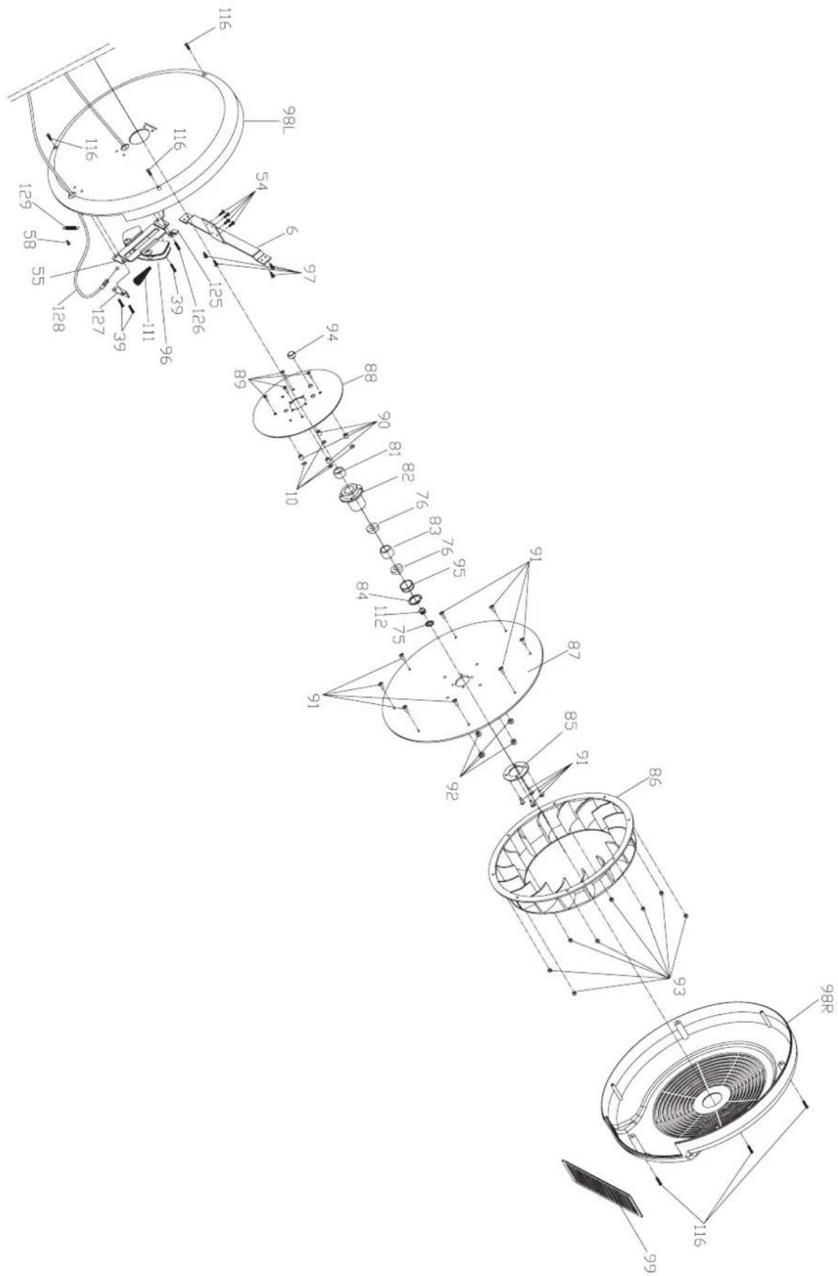
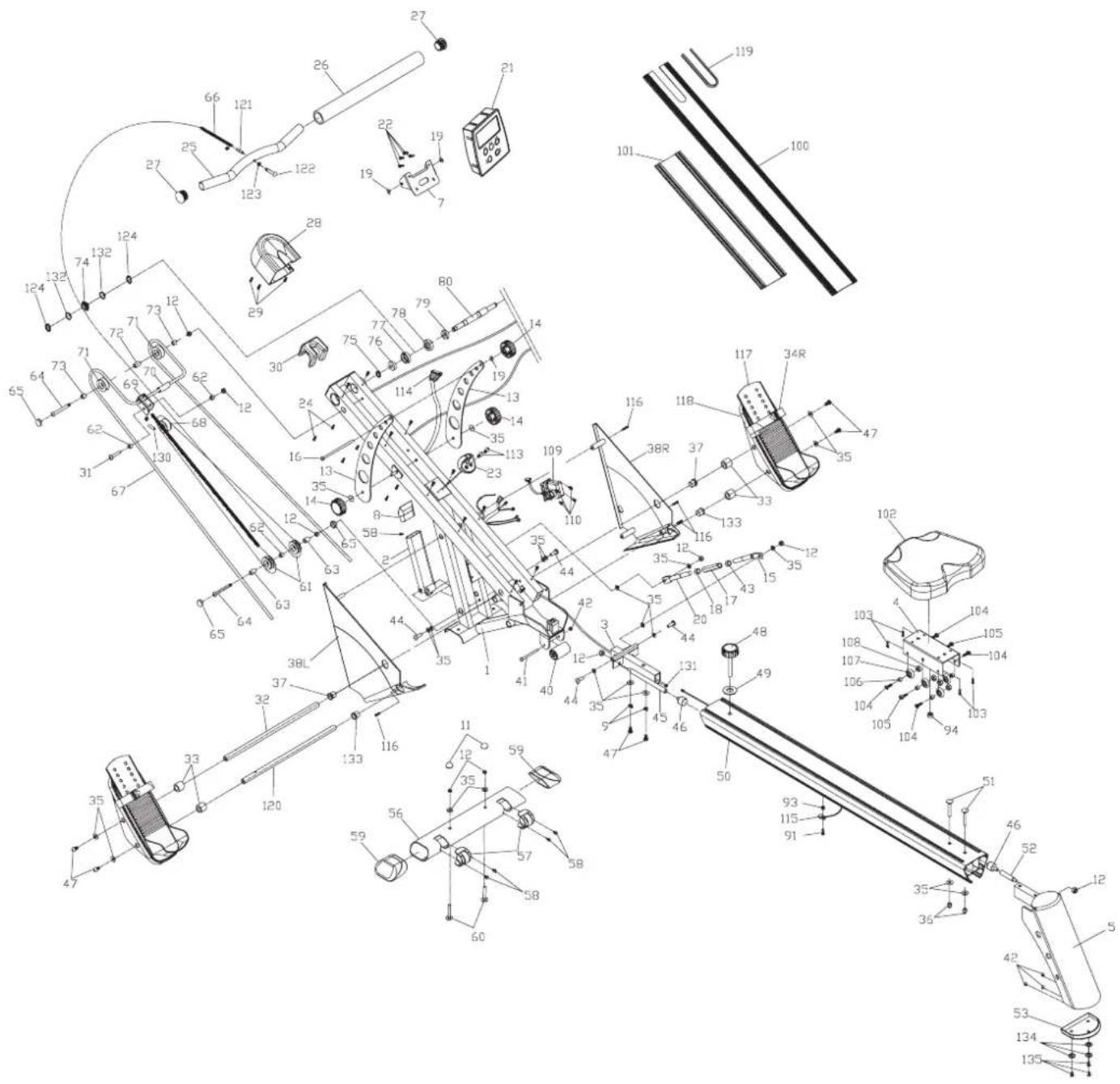
Ref.QtyPartno.PartDescriptionRef.QtyPartno.PartDescription
| 1 | 1 | 56004-01MainFrame(C) |
| 2 | 1 | 56004-02FoldableFrontPost |
| 3 | 1 | 56004-03FoldableFixingSupport |
| 4 | 1 | 56004-04SeatCarriageBracket |
| 5 | 1 | 56004-05RearStabilizer |
| 6 | 1 | 56004-06FanCoverFixingBracket |
| 7 | 1 | 56004-07ComputerConsoleFixingbracket |
| 8 | 1 | 56004-08FoldableFrontPostEndCap |
| 9 | 2 | 56004-09SpringWahser(ID-8) |
| 10 | 4 | 56004-10FlatWasher(ID-6xOD-12xT-0.25mm) |
| 11 | 2 | 56004-11RoundPlasticBoltCap(M8) |
| 12 | 9 | 56004-12NylonLocknut(M8) |
| 13 | 2 | 56004-13ConsoleFixingPlate |
| 14 | 3 | 56004-14HandWheelKnob-Female |
| 15 | 1 | 56004-15FoldableLinkageRod-Rear(M12x150mm) |
| 16 | 1 | 56004-16CarriageBolt(M8x140mm) |
| 17 | 1 | 56004-17AdjustableLinkageMetalSleeve(M12 x 90mm) |
| 18 | 1 | 56004-18HexNut(M12)-ClockwiseThreads |
| 19 | 3 | 56004-19FlatWasher(ID-8xOD-16xT-1.0mm) |
| 20 | 1 | 56004-20FoldableLinkageRod-Front(M12x149mm) |
| 21 | 1 | 56004-21ComputerConsoleAssembly |
| 22 | 4 | 56004-22RoundPhilipsHeadMachineScrew(M5x15mm) |
| 23 | 1 | 56004-23PullingHandlebarHolder |
| 2416 | 56004-24FlatPhilipsHeadSelfTappingScrew(M5x12.5mm) | |
| 25 | 1 | 56004-25Pulling Handle Bar (OD-25.4 x 600mm x T-1.5mm) |
| 26 | 1 | 56004-26Pulling Handle Bar Foam Grip (OD-25.4x610mmxT-5mm) |
| 27 | 256004-27RoundInternalTopHatEndCap | |
| 28 | 156004-28FrontMainPost Cover | |
| 29 | 356004-29RoundPhilipsHeadSelfTappingScrew(M5x20mm) | |
| 30 | 156004-30Pulling Chain Guard -Rubber | |
| 31 | 1 | 56004-31RoundAllen HeadBolt(M8x40mm) |
| 32 | 1 | 56004-32Pedal Pivot Rod(OD-16x420mm) |
| 33 | 4 | 56004-33Plastic Spacer (OD-26 x ID-16 x 23.6mm) |
| 34 | PAIR | 56004-34Pedal W/Strap Assembly(L&R) |
| 3522 | 56004-35Flat Washer(ID-8xOD-19xT-1.5mm) | |
| 36 | 3 | 56004-36Nyloc Cap Nut(M8) |
| 37 | 2 | 56004-37Pedal Pivot Rod Bushing (OD-22 x ID-16 x 18mm x T-3mm) |
| 38 | PAIR | 56004-38Bottom Cover ( L & R ) |
| 39 | 3 | 56004-39Round Philips Head Self Tapping Screw (M5 x 25mm) |
| 40 | 1 | 56004-40Rear Moving Roller |
| 41 | 1 | 56004-41Round Allen Head Bolt (M6 x 75mm) |
| 42 | 4 | 56004-42Nyloc Cap Nut (M6) |
| 43 | 1 | 56004-43Hex Nut (M12) - Anti-Clockwise Threads |
| 44 | 4 | 56004-44Round Allen Head Bolt (M8 x 25mm) |
| 45 | 1 | 56004-45Front Stop Rod (OD-13 x 170mm) |
| 46 | 2 | 56004-46Rubber Stop |
| 47 | 6 | 56004-47Round Allen Head Bolt (M8 x 20mm) |
| 48 | 1 | 56004-48Hand Wheel Knob - Male (M12 x 80mm) |
| 49 | 1 | 56004-49Flat Washer (ID-13 x OD-28 x T-2mm) |
| 50 | 1 | 56004-50Rower Seat Track (110mm x 81.74mm x 1200mm ) |
| 51 | 2 | 56004-51Carriage Bolt (M8 x 55mm) |
| 52 | 1 | 56004-52Rear Stop Rod (OD-13 x 70mm) |
| 53 | 1 | 56004-53Rear Stabilizer External End Cap |
| 54 | 4 | 56004-54Flat Philips Head Machine Screw (M6 x12mm) |
| 55 | 1 | 56004-55Magnet Resistance Assembly Guide Plate |
| 56 | 1 | 56004-56Front Stabilizer |
| 57 | 2 | 56004-57Front Stabilizer Moving Wheel Assembly |
| 58 | 6 | 56004-58Round Philips Head Self Tapping Screw (M4 x 12mm) |
| 59 | 2 | 56004-59Front Stabilizer External End Cap |
| 60 | 2 | 56004-60Carriage Bolt (M8 x 45mm) |
| 61 | 2 | 56004-61Pulling Chain Roller |
| 62 | 3 | 56004-62Metal Sleeve (OD-13 x ID-8.2 x 9mm) |
| 63 | 2 | 56004-63Metal Sleeve (OD-13 x ID-8.2 x 19mm) |
| 64 | 2 | 56004-64Round Allen Head Bolt (M8 x 75mm) |
| 65 | 3 | 56004-65Main Post Internal End Cap |
| 66 | 156004-66Pulling Chain-528link/3360mmL | |
| 67 | 1 | 56004-67Elastic Cord (OD-9 x 1500mm) |
| 68 | 1 | 56004-68Pulling Chain Roller (OD-36 x ID-26 x 20mm H) |
| 69 | 1 | 56004-69Elastic Cord Fixing Bracket |
| 70 | 1 | 56004-70Elastic Cord Plastic Sleeve |
| 71 | 2 | 56004-71ElasticCordRoller |
| 72 | 1 | 56004-72MetalSleeve(OD-13xID-8.2x33mm) |
| 73 | 2 | 56004-73MetalSleeve(OD-13xID-8.2x7mm) |
| 74 | 1 | 56004-74ChainWheel |
| 75 | 2 | 56004-75CClip(forOD.12.7shaft) |
| 76 | 3 | 56004-76Bearing(R8z) |
| 77 | 1 | 56004-77R8zRubberBushing(OD-36xID-24x10mm) |
| 78 | 1 | 56004-78RubperBushing-6903z(OD-36xID-24x10mm) |
| 79 | 1 | 56004-79Bearing(6903z) |
| 80 | 1 | 56004-80PivotShaft(OD-19x193mm) |
| 81 | 1 | 56004-81OneWayBearing(RC-121610) |
| 82 | 1 | 56004-82Air Fan Pivot Bushing (OD-70 x 57mm) |
| 83 | 1 | 56004-83MetalSleeve(OD-28xID-22x20mm) |
| 84 | 1 | 56004-84CClip(forID.28.5 shaft) |
| 85 | 1 | 56004-85AirFanFixingPlate(OD-70xID-37.5xT-2.5mm) |
| 86 | 1 | 56004-86AirFan |
| 87 | 1 | 56004-87AirFanFixingDisc(OD-390xID-37.2xT-4mm) |
| 88 | 1 | 56004-88MetalResistanceDisc(OD-235xID-42xT-2mm) |
| 89 | 4 | 56004-89RoundPhilipsHeadMachineScrew(M6x38mm) |
| 90 | 4 | 56004-90MetalSleeve(OD-10xID-6.2x10mm) |
| 91 | 13 | 56004-91RoundPhilipsHeadMachineScrew(M5x15mm) |
| 92 | 4 | 56004-92NylonLocknut(M6) |
| 93 | 9 | 56004-93NylonLocknut(M5) |
| 94 | 2 | 56004-94Magnet |
| 95 | 3 | 56004-95FlatWasher(ID-28.3xOD-25.5xT-0.4mm) |
| 96 | SET | 56004-96MagneticResistanceAssembly |
| 97 | 4 | 56004-97RoundPhilipsHeadSelfTappingScrew(M5x15mm) |
| 98 | PAIR | 56004-98AirFanCover(L&R) |
| 99 | 1 | 56004-99AirVent |
| 100 | 1 | 56004-100TopRailCover |
| 101 | 1 | 56004-101BottomRailCover |
| 102 | 1 | 56004-102RowerSeat |
| 103 | 6 | 56004-103RoundPhilipsHeadMachineScrew(M6x15mm) |
| 104 | 4 | 56004-104FlatAllenHeadShoulderBolt(M8x20mm) |
| 105 | 2 | 56004-105Cambolt(M8x20mm) |
| 106 | 6 | 56004-106MetalSleeve(OD-13xID-8.2x5.4mm) |
| 107 | 6 | 56004-107Seat Carriage Roller |
| 108 | 6 | 56004-108Hex Nut (M8 x 4H) |
| 109 | 1 | 56004-109Servo Motor Assembly (MBSYT) |
| 110 | 4 | 56004-110Dome Philips Head Machine Screw (M5 x8mm) |
| 111 | 1 | 56004-111Spring (OD-15 x ID-5 x 80mm) |
| 112 | 5 | 56004-112Flat Washer (ID-12.9 x OD-16.5 x T-0.4mm) |
| 113 | 2 | 56004-113Round Philips Head Machine Screw (M4 x10mm) |
| 114 | 1 | 56004-114Servo Motor Connect Wire |
| 115 | 1 | 56004-115Counter Sensor Wire |
| 116 | 10 | 56004-116Round Philips Head Self Tapping Screw (M4 x 25mm) |
| 117 | 2 | 56004-117Top Foot Pedal Pad |
| 118 | 2 | 56004-118Bottom Foot Pedal |
| 119 | 1 | 56004-119Rubber Strip |
| 120 | 1 | 56004-120Pedal Pivot Rod (OD-16 x 417mm) |
| 121 | 1 | 56004-121Rubber Sleeve (OD- 10 x ID- 6 x 40mm) |
| 122 | 1 | 56004-122Pulling ChainConnectBolt(M8x41mm) |
| 123 | 1 | 56004-123Pulling Chain Connect Washer (ID- 10mm) |
| 124 | 2 | 56004-124C Clip (for OD.19.4 shaft) |
| 125 | 1 | 56004-125Speed Sensor Wire |
| 126 | 1 | 56004-126Round Philips Head Self Tapping Screw (M5 x 30mm) |
| 127 | 1 | 56004-127Fixing Bracket |
| 128 | 1 | 56004-128Resistance Connect Cable |
| 129 | 1 | 56004-129Pulling Spring (OD-10 x 20mmL) |
| 130 | 1 | 56004-130Rubber Sleeve (OD- 10 x ID- 6 x 20mm) |
| 131 | 1 | 56004-131Middle Wire |
| 132 | 2 | 56004-132Pulling Chain Rubber Ring (OD-23 x ID-19.5 x 3mm) |
| 133 | 2 | 56004-133Pedal Pivot Rod Bushing (OD- 22 x ID- 16 x 18mm x T- 4.5mm) |
| 134 | 3 | 56004-134Flat Washer (ID-10 x OD-16 x T-1.5mm) |
| 135 | 3 | 56004-135Countersunk Philips Head Machine Screw (M6 x 12mm) |
| TOOLS | ||
| 1 | 56004-136Instruction Manual | |
| 2 | 56004-137Allen Key | |
| 1 | 56004-138Combined nut driver & Philips head screwdriver |
EXPLODED DRAWING
NOTE
NOTE
NOTE
NOTE
YORK®
FITNESS
- SAFETY INFORMATION
- SAFETY PRECAUTIONS
- DISCLAIMER
- EQUIPMENT SAFETY:
- FITNESS PRECAUTIONS:
- EXERCISE SAFETY:
- USER WEIGHT: 120KG
- SAFETY STANDARDS
- CUSTOMER SUPPORT
- CONTACT INFORMATION
- York Fitness U.K. Ltd. (England)
- York Fitness (Australia) Pty. Ltd.
- PLEASE RETAIN
- TABLE OF CONTENTS
- Thank you for choosing
- YORK® FITNESS
- ASSEMBLY INSTRUCTIONS
- GETTING STARTED
- HARDWARE IDENTIFICATION CHART
- STEP 1
- STEP 2
- STEP 3
- STEP 4
- STEP 5
- STEP 6
- STEP 7
- STEP 8
- STEP 9
- FINAL CHECK
- BATTERY REPLACEMENT INSTRUCTIONS:
- TIPS & WARNINGS
- OPERATION INSTRUCTIONS
- USING WORKOUT PROGRAMS
- STORAGE
- CLEANING
- MAINTENANCE
- TROUBLESHOOTING
- FOLD FOR STORAGE
- UNFOLD FOR USE
- FITNESS GUIDE
- EXERCISING WITH YOUR ROWER
- HOW TO ROW:
- ALTERNATIVE EXERCISE - LEG ONLY ROWING:
- CONDITIONING GUIDELINES:
- THIS PRODUCT IS SUPPLIED WITH A STANDARD WARRANTY AS FOLLOWS:
- WARRANTY TERMS
- TO OBTAIN WARRANTY SERVICE YOU MUST PROVIDE THE FOLLOWING INFORMATION:
- EXPLODED DRAWING
- NOTE
- YORK®
- FITNESS
Brand : York Fitness
Model : Diamond R301
Category : Rowing Machine