
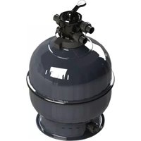
XC 75 - Water filter ASTRALPOOL - Free user manual and instructions
Find the device manual for free XC 75 ASTRALPOOL in PDF.


| Product Type | Pool & Spa Cartridge Filter |
| Brand | AstralPool |
| Model | XC 75 |
| Category | Water Filter |
| Filter Area | 7.0 m² |
| Max Flow Rate | 290 L/min (17,400 L/hr) |
| Max Working Pressure | 250 kPa (36 PSI) |
| Recommended Pump Power | 550–1100 W |
| Shipping Weight | 14.2 kg |
| Replacement Cartridge Code | SP78021 |
| Model Number | 30041 |
| Tank Material | Glass fibre reinforced plastic |
| Inlet Ports | 2 (1 active, 1 blanked) |
| Outlet Ports | 1 |
| Drain Port | Yes (with drain cap) |
| Max Water Temperature | 38°C (100°F) |
| Filter Type | Cartridge (cleanable/replaceable) |
| Installation Requirements | Stable level base, under cover, away from heat |
| Cleaning Frequency | Fortnightly or when pressure rises >20 kPa |
| Included Accessories | Air relief valve, pressure gauge, handles, blanking cap, inlet/outlet fittings, drain cap, cartridge, manual, warranty card |
Frequently Asked Questions - XC 75 ASTRALPOOL
User questions about XC 75 ASTRALPOOL
0 question about this device. Answer the ones you know or ask your own.
Ask a new question about this device
Download the instructions for your Water filter in PDF format for free! Find your manual XC 75 - ASTRALPOOL and take your electronic device back in hand. On this page are published all the documents necessary for the use of your device. XC 75 by ASTRALPOOL.
USER MANUAL XC 75 ASTRALPOOL
INSTALLATION AND OPERATION MANUAL
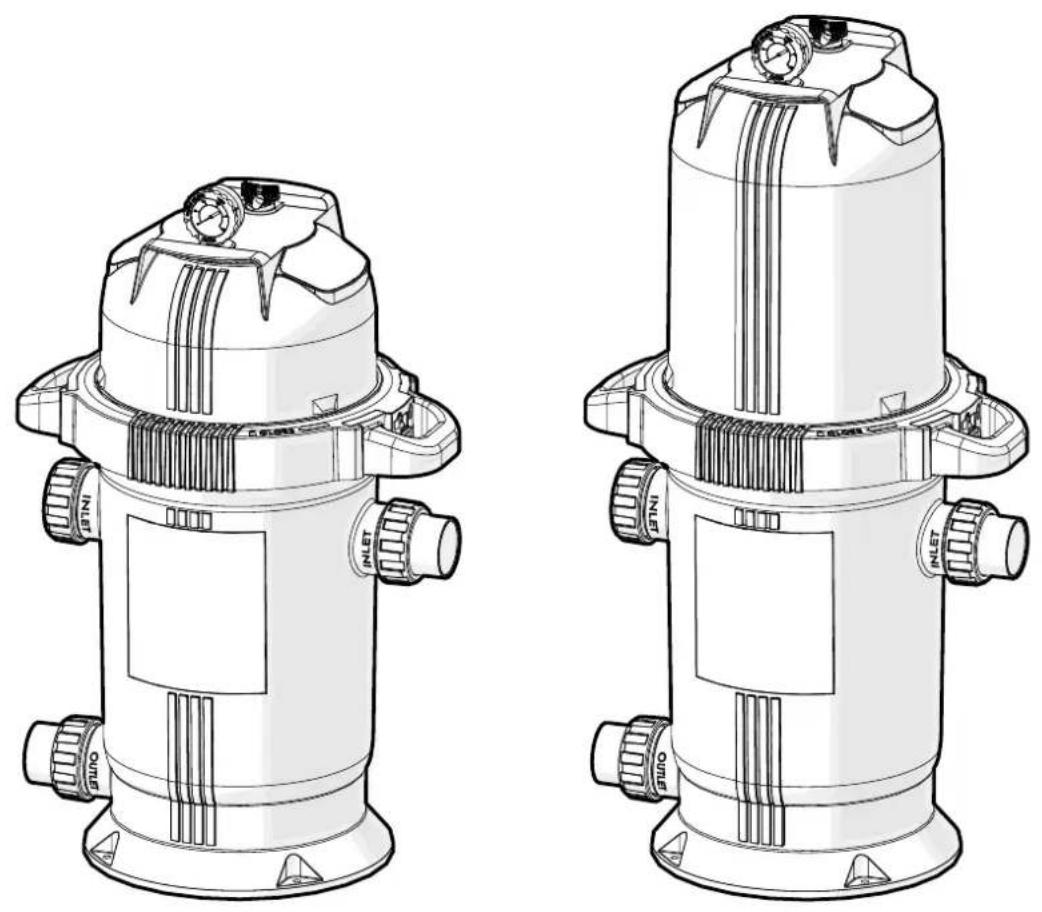
XC-SERIES
POOL & SPA CARTRIDGE FILTER
! WARNING
FOR YOUR SAFETY - This product must be installed and serviced by a contractor who is licensed and qualified on pool equipment in accordance with the latest applicable version of AS3633, along with any other applicable local or council codes/standards. Before installing this product, read and follow all warning notices and instructions that accompany this product. Failure to follow warning notices and instructions may result in property damage, personal injury, or death.
Improper installation and/or operation will void the warranty. Improper installation and/or operation can create unwanted hazards which can cause serious injury, property damage, or death.
| WARRANTY REGISTRATION | Record your equipment details here for quick reference:Model No.: ____Serial No.: ____ |
 | AUSTRALIA WARRANTY:For full warranty terms and conditions and to register your warranty, visitwww.astralpool.com.au/warrantyand complete your details.◀ Or scan the QR code to go directly to the registration page. |
 | NEW ZEALAND WARRANTY:For full warranty terms and conditions and to register your warranty, visitwww.astralpool.co.nz/warrantyand complete your details.◀ Or scan the QR code to go directly to the registration page. |
EQUIPMENT INFORMATION RECORD
DATE OF INSTALLATION
INSTALLER INFORMATION
FILTER MODEL
PUMP HORSEPOWER
INITIAL PRESSURE GAUGE READING
(WITH CLEAN FILTER)
SERIAL NUMBER
NOTES
TABLE OF CONTENTS
Section 1. Important Safety Instructions .... 4
Section 2. General Information .... 5
2.1 Introduction....5
2.2 Technical Assistance....5
2.3 Description....5
2.4 XC-Series Specifications and Dimensions....6
Section 3. Installation Instructions .... 7
3.1 Inside the Box 7
3.2 Required Tools ....7
3.3 Installation....8
Section 4. Start-Up and Operation....10
Section 5. Maintenance .... 11
5.1 General Maintenance....11
5.2 Maintenance Schedule ......11
5.3 Filter Cartridge Cleaning/Replacement....11
Section 6. Troubleshooting....13
Section 1. Important Safety Instructions
READ AND FOLLOW ALL INSTRUCTIONS
This product should only be installed and serviced by a qualified pool professional and conform to all national, state, and local codes. When installing and servicing, basic safety precautions should always be followed, including the following:
WARNING
Do not connect system to an unregulated city water system or other external source of pressurised water producing pressures greater than 250 KPA (36 PSI).
Pressurised air in system can cause the filter lid to be blown off which can result in death, serious personal injury, or property damage. Be sure all air is out of system before operating or testing the equipment.
WARNING
MAXIMUM OPERATING PRESSURE OF THE FILTER IS 250 KPA (36 PSI). NEVER SUBJECT THE FILTER TO ANY OPERATING PRESSURE EXCEEDING 250 KPA (36 PSI).
This filter operates under high pressure. When any part of the circulating system, i.e., filter, pump, valve(s), clamp, etc. is serviced, air can enter the system and become pressurised when the system is restarted. Pressurised air can cause the filter lid to be blown off which can result in death, serious personal injury or property damage. To avoid this potential hazard, follow all of the instructions in this manual.
WARNING
To minimise risk of severe injury or death the filter and/or pump should not be subjected to the piping system pressurisation test.
Local codes may require the pool piping system to be subjected to a pressure test. These requirements are generally not intended to apply to the pool equipment such as filters or pumps.
AstralPool equipment is pressure tested at the factory.
If however this WARNING cannot be followed and pressure testing of the piping system must include the filter and/or pump BE SURE TO COMPLY WITH THE FOLLOWING SAFETY INSTRUCTIONS:
Check all clamps, bolts, lids, lock rings and system accessories to ensure they are properly installed and secured before testing. RELEASE ALL AIR in the system before testing.
Water pressure for test must NOT EXCEED 250 KPA (36 PSI).
Water temperature for test must NOT EXCEED 38°C (100°F).
Limit test to 24 hours. After test, visually check system to be sure it is ready for operation.
Notice: These parameters apply to AstralPool equipment only. For non-AstralPool equipment, consult equipment manufacturer.
WARNING
Chemical spills and fumes can weaken pool/spa equipment. Corrosion can cause filters and other equipment to fail, resulting in severe injury or property damage. Do not store pool chemicals near your equipment.
WARNING
Incorrectly installed equipment may fail, causing severe injury or property damage.
WARNING
To reduce the risk of injury, do not permit children to use this product.
Section 2. General Information
2.1 Introduction
Congratulations on the purchase of your AstralPool XC-series cartridge filter. The XC-series filters are made to last by utilising the best quality materials available. The tank is made from high quality and high strength glass fibre reinforced plastics, capable of withstanding the harshest environments.
This manual provides installation and operation instructions for the AstralPool XC-series cartridge filter. Read the installation and operation instructions completely before proceeding with the installation.
2.2 Technical Assistance
For technical assistance, in Australia please visit www.astralpool.com.au or call at 1300 186 875, in New Zealand please visit www.astralpool.co.nz or call at 0800 807 665.
2.3 Description
Cartridge filters do not require sand or diatomaceous earth as the filter medium. Instead, the filter contains filter elements which are easily removed for cleaning or replacement.
Dirty water flows into the filter tank through the water line connected to the inlet of the tank body. It is directed through the filter cartridge inside of the filter. The debris is collected in the filter and the clean water flows out of the filter through the outlet on the bottom of the tank body. Clean water is returned through the piping system to the pool.
As debris collects in the filter, the pressure will rise and water flow to the pool will reduce. The filter will eventually become so clogged with debris that it will be necessary to remove the filter cartridges and clean them with soap and water.
NOTE: A filter removes dirt and other suspended particles but does not sanitise the pool. Pool water must be sanitised and chemically balanced for clear water. The filtration system should be designed to meet local health codes.
2.4 XC-Series Specifications and Dimensions
| FILTER MODEL | MODEL NO. | REPLACEMENT ELEMENT CODE | FILTER AREA (M2) | MAX. FLOW RATE (L/MIN) | MAX. FLOW RATE (L/HR) | 4 HR TURN OVER (L) | 6 HR TURN OVER (L) | MAX. WORKING PRESSURE (KPA) | PUMP SIZE (W) | SHIPPING WEIGHT (KG) |
| XC50 | 30040 | SP78020 | 4.7 | 225 | 13,500 | 54,000 | 81,000 | 250 | 550-750 | 13.6 |
| XC75 | 30041 | SP78021 | 7.0 | 290 | 17,400 | 69,600 | 104,400 | 250 | 550-1100 | 14.2 |
| XC100 | 30042 | SP78097 | 9.3 | 375 | 22,500 | 90,000 | 135,000 | 250 | 750-1100 | 14.4 |
| XC150 | 30043 | SP78059 | 14.0 | 445 | 26,700 | 106,800 | 160,200 | 250 | 750 -1500 | 16.6 |
| XC200 | 30044 | SP78099 | 18.6 | 490 | 29,400 | 117,600 | 176,400 | 250 | 750-1500 | 17.0 |
| XC250 | 30045 | SP78094 | 23.2 | 515 | 30,900 | 123,600 | 185,400 | 250 | 750-1500 | 17.5 |


Figure 1. XC-Series Filter Dimensions
Section 3. Installation Instructions
Follow the step-by-step instructions to avoid any accidents and to ensure proper installation of the filter.
3.1 Inside the Box
Make sure all the parts are included in the product package. If you have a problem with the filter or the parts, contact AstralPool or the retailer for technical assistance.
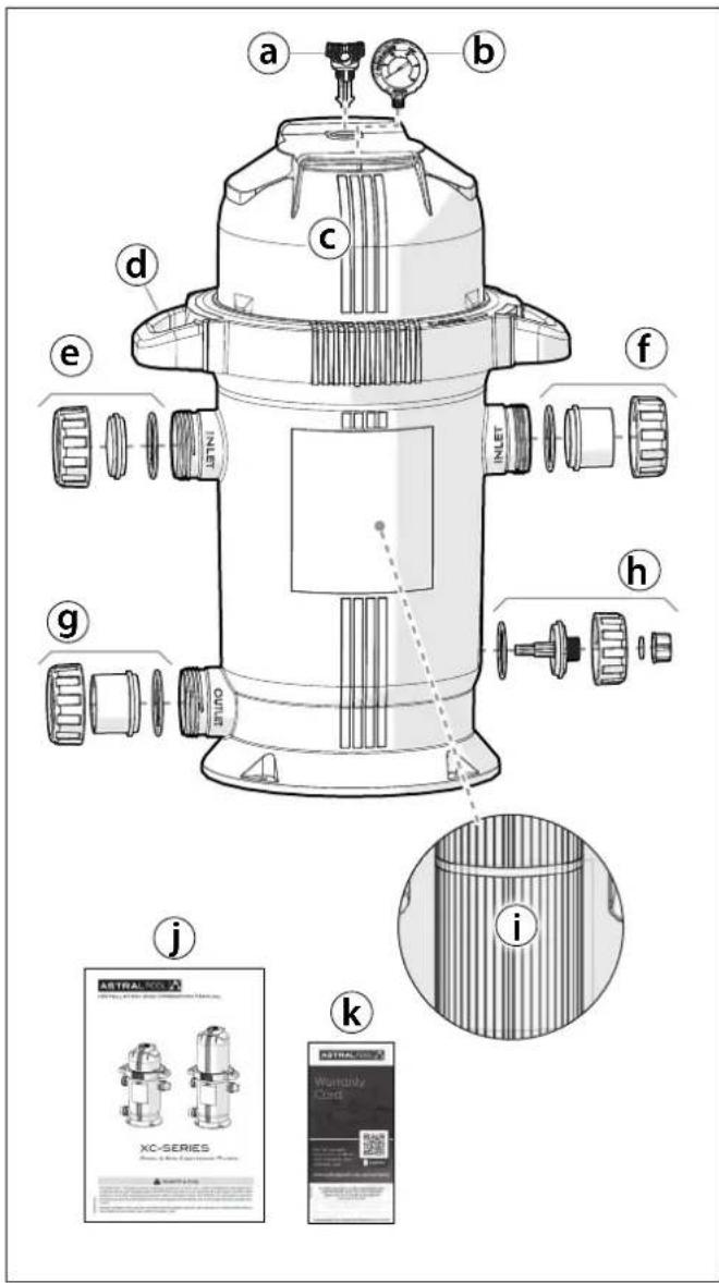
Figure 2. XC-Series Package Contents
XC-Series Package Contents (Figure 2)
a. Air Relief Valve w/ O-ring
b. Pressure Gauge
c. Filter Housing
d. Handles
e. Blanking Cap w/ Fittings
f. Inlet Fittings
g. Outlet Fittings
h. Drain Cap Assembly (rear)
i. Filter Cartridge (installed)
j. Installation and Operation Manual
k. Warranty Card
3.2 Required Tools
Please ensure that the following equipment is available to the installer at the time of installation:

3.3 Installation
- The cartridge filter must be installed on a clean, stable and level base.
- The location of the filter should ideally be under cover away from direct sunlight and away from heat sources.
- Attach the handles to the filter by sliding vertically into the slots in the locking ring (Figure 3). Press down until you hear the tabs click into place.
NOTE: Each handle fits only one side. Match the handles to the slots.

Figure 3. Handle Attachments
- The XC-series filter has four ports in total - two inlet ports (from pump), one outlet port (to pool/spa) and one drain port (Figure 4).
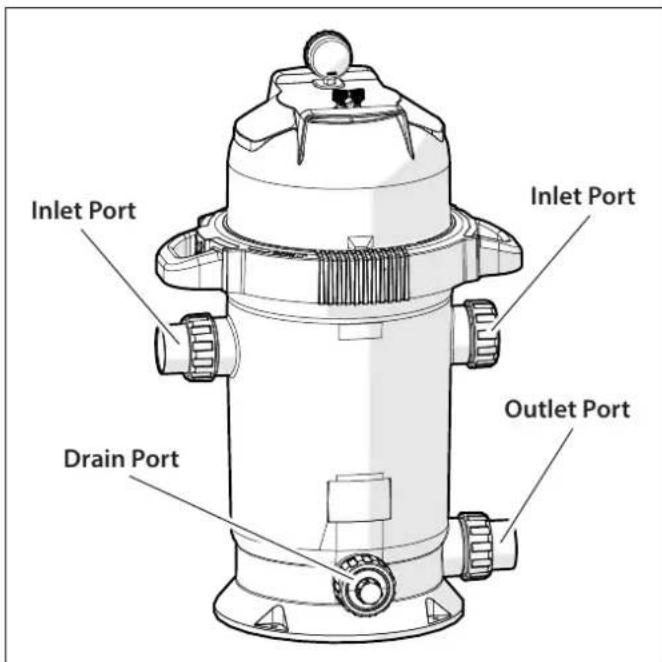
Figure 4. Filter Ports
- Either inlet port can be used. While one inlet is in use (active inlet), the other (passive inlet) must be
blocked using the blanking cap supplied with the product.
NOTE: Both inlets may be used in an optional configuration (second tail union not included).
- Glue the water connection pipe from the pump to the inlet tail union (Figure 5). Glue the pool returns water connection pipe to the outlet tail union. Ensure locking nuts are placed on tail union before gluing connection pipes. Allow 24 hours for glue to dry before subjecting filter to system pressures.
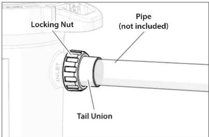
Figure 5. Plumbing Connections
- Install the O-ring on the tail union, then screw the locking nut onto the active inlet. The O-ring must be clean and avoid any twisting. Install the tail union on the outlet of the filter in the same manner (Figure 6).

Figure 6. Inlet Fittings
-
Block the second (passive) inlet using a blanking cap, O-ring and locking nut (Figure 6).
-
Each inlet is fitted with a water deflector. These deflectors must remain in place to prevent damage to the filter due to high-speed water flow from the pump (Figure 7).
NOTE: Both inlet water deflectors are installed at the factory.

Figure 7. Water Deflectors
- Install the drain cap assembly into drain port (Figure 8).

Figure 8. Drain Cap
- Assemble the pressure gauge with front and rear casings (Figure 9).

Figure 9. Pressure Gauge Casings
-
Apply Teflon tape (not included) to the pressure gauge and screw into lid where indicated (Figure 10).
-
Install the air relief valve (also known as air bleed valve) into the lid (Figure 10).

Figure 10. Pressure Gauge and Air Relief Valve Installation
Section 4. Start-Up and Operation

flowchart
graph LR
    A["Heater"] --> B["Check Valve"]
    B --> C["Valve"]
    C --> D["Pool Return"]
    D --> E["Drain"]
    E --> F["Outlet Inlet"]
    F --> G["XC-Series Filter"]
    G --> H["Pump"]
    G --> I["Valve"]
    I --> J["From Pool"]
Figure 11. Basic Pool Plumbing
- Turn off the pump and disconnect any additional power source that is connected to the system.
- Check that the locking nuts on all four ports are in place and tight (inlet, outlet, drain cap and blanking cap).
- Make sure the filter cartridge is installed in the filter housing.
NOTE: The cartridge is installed at the factory, ready for the first start-up.
- Make sure the locking ring is closed tight (fully clockwise) and the locking tab is engaged. When closing the locking ring, the locking tab will "click" as it engages (Figure 12).

Figure 12. Secure Locking Ring
- Open the pump hair/lint pot lid and fill the pump basket with water to prime the system. Replace the lid (you may have to do this several times on new start-ups).
-
Open the suction and return line valves (if fitted).
-
Stand clear of the filter. Start pump and open the air relief valve on the filter lid about three-quarter turn – until you hear air being forced from the tank (Figure 13).

Figure 13. Open Air Relief Valve
- Once water begins to flow from the valve, tighten to close. Check there is a good flow of water back into the pool.
- Watch the pressure gauge to make sure the pressure stays below 250 kPa or 36 PSI. If the pressure approaches 250 kPa, immediately turn the pump off and clean the filter cartridges (see Section 5 "Maintenance"). If the pressure remains high after cleaning the filter, refer to the troubleshooting guide (Section 6 "Troubleshooting") for possible causes and solutions.
- When the filter is first installed, make a note of the pressure gauge reading in the Equipment Information Record Table (page 2). Follow the Maintenance Schedule to clean or replace the cartridge when the flow to the pool reduces or the pressure gauge increase is more than 20 kPa. (see Section 5 "Maintenance").
Section 5. Maintenance
5.1 General Maintenance
Filter incorporates moving parts and withstands high velocity water with chemicals in it. It is important to note that over time some of these parts will wear in the normal course of use and require regular checks, maintenance and possible replacement.
Performing the maintenance checks below will help to identify parts that have worn and require repair/replacement before further serious damage is sustained. Please note that repair/replacement of moving parts due to regular wear and tear are the responsibility of the pool owner(s) and are not deemed to be covered under warranty. A small amount of regular care and attention to pool equipment will help ensure long life and trouble-free performance.
5.2 Maintenance Schedule
| FORTNIGHTLY |
| MAINTENANCE CHECK:Check pressure gauge - If pressure increase is greater than 20 kPa, cleaning may be required.SERVICE ACTION (if needed): Clean elements using a garden hose with nozzle or purpose element cleaner In accordance with instructions. |
| THREE MONTHLY |
| MAINTENANCE CHECK:Check inlet/outlet O-rings for leaks.SERVICE ACTION (if needed): Isolate Pump, turn power off, clean and grease O-rings or replace if necessary. |
| MAINTENANCE CHECK:Check operation of pressure gauge – salt water can prematurely reduce the life of a gauge.SERVICE ACTION (if needed): Replace gauge if required. |
| ANNUALLY |
| MAINTENANCE CHECK:Compare operating pressure of a cleaned filter to initial pressure (when new).SERVICE ACTION (if needed): If pressure is more than 30 – 40 kPa different from cleaned elements to new filter, replace elements. |
| MAINTENANCE CHECK:Check for signs of damage to elements.SERVICE ACTION (if needed): Replace elements. |
IMPORTANT NOTE:
Regular maintenance is important to ensure long life and trouble-free performance of your pool equipment. If unable to perform the maintenance yourself, contact your local AstralPool office who will be happy to arrange a trained service technician to perform the maintenance for you.
5.3 Filter Cartridge Cleaning/Replacement
- Turn off the pump and any additional power source that is connected to assure the system will not inadvertently start during service.
IMPORTANT: Open the air relief valve (also known as air bleed valve) about three-quarter turn on the filter lid and wait until the pressure gauge reading is zero (0).
- Close the filter isolation valves (suction and return) on the system to prevent flooding.
- Remove the drain cap located at the bottom of the filter main body to drain water (Figure 14).
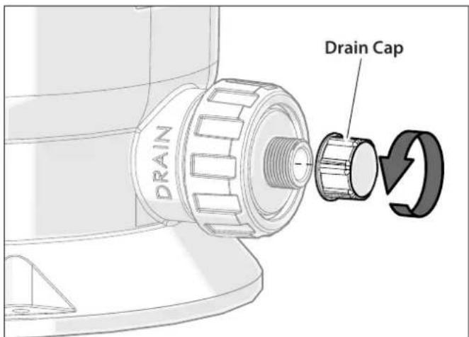
Figure 14. Drain Filter
- Replace the drain cap.
- Loosen the locking ring on filter. Pull up on the locking ring release tab and hold while turning the locking ring counterclockwise (Figure 15).
NOTE: NEVER LOOSEN THE LOCKING RING WHEN THE PUMP IS ON!
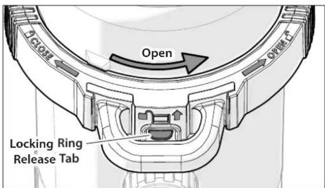
Figure 15. Locking Ring Release Tab
- Once lid is free of the body, lift lid and locking ring together and place in a clean location. You can now remove the filter cartridge (Figure 16).

natural_image
Technical line drawing of a mechanical component with a central cylindrical assembly and an upward arrow indicating motion (no text or symbols)Figure 16. Removing Cartridge
- Pull the cartridge out of the filter tank. If replacing the cartridge with a new one, skip this step. To clean the filter, soak it in a mild solution of chlorine and warm water for 15 minutes, then hose off with water.
NOTE: Special formulated filter element cleaning solutions can be purchased from most pool professionals.
NOTE: Do not use high powered water jets to clean the elements, which may cause damage. Using a garden hose with nozzle will do the job safely.
- Using a new or cleaned cartridge, place the cartridge into the filter tank. Be sure that the filter cartridge is correctly seated on the cartridge support at the bottom spigot of the filter main body (Figure 17).

Figure 17. Cartridge Support
- Inspect the main O-ring at the lid for cracks and wear marks. Replace if necessary. Use only a non-petroleum based lubricant on all gaskets and lid O-rings.
- Replace the lid and locking ring assembly onto the top of the filter tank, ensuring correct alignment with the threads.
- Tighten the lid locking ring in a clockwise direction. The lid will pull down onto the filter tank until you will hear a "click" sound when the locking tab has engaged (Figure 18).

Figure 18. Closing the Locking Ring
- Start the system by following the procedures outlined in Section 4 "Start-Up and Operation"
Section 6. Troubleshooting
- For a list of common problems and solutions see the Troubleshooting Guide below.
- AstralPool recommends that you call a qualified service technician to do any work on the filter/pump system. For technical service, in Australia please call 1300 186 875, in New Zealand please call 0800 807 665.
| FAULT SYMPTOM POSSIBLE PROBLEMS SOLUTIONS | ||
| Water is not clear | Insufficient disinfectant level. Check and adjust disinfectant level. | |
| Incorrect pool chemistry. Test and adjust water chemistry. | ||
| Heavy bathing and/or dirt loads. Adjust filter time and/or water chemistry. | ||
| Insufficient running times. Increase pump run time. | ||
| Filter is dirty. Clean filter cartridges per instructions. | ||
| Hole in filter element. | Replace cartridge. | |
| Low water flow | Filter system strainer baskets dirty. | Check and clean strainer baskets. |
| Air leaks on suction side of pump. | Check all connections between pool intake and pump. | |
| Restrictions or blockage in either suction or return lines. | Check all lines for debris or partially closed valves. | |
| Filter cartridges need to be cleaned or replaced. | Clean or replace filter cartridges per instructions. | |
| Pool water level too low. | Fill pool so level is above pump inlet line. | |
| Pump not primed. | Fill pump with water at basket and replace lid. | |
| Pump impeller vanes blocked. | Technician required. | |
| Strainer baskets not being used and/or broken (Allowing debris into pump). | Replace baskets. | |
| Pump operating under speed (low voltage). | Technician or electrician required. | |
| Short filter cycles | Presence of algae clogging filter. Check disinfectant content. | |
| Incorrect water chemistry. | Check pH, total alkalinity and TDS. | |
| Pump output exceeds design flow rate of filter. | Check pump performance. | |
| Ineffective cleaning. | Clean or replace filter cartridge per instructions. | |
| High pressure on start-up | Small eyeball fitting in Pool/Spa. | Replace with larger diameter fitting. |
| Partially closed valve on return line. Check and fully open all valves on return line. | ||
| Too large of pump. | Check pump and filter selection. | |
| Filter cartridges dirty. | Clean filter cartridges per instructions. | |
| Dirt returns to pool | Hole in filter cartridge. | Replace filter cartridge per instructions. |
| Worn o-ring seal inside filter. | Replace o-ring. | |
NOTES
NOTES

H0785300
Fluidra Group Australia Pty Ltd
PO Box 7238, Wetherill Park NSW 2164
ABN: 87 002 641 965
1300 763 021 | AstralPool.com.au
Fluidra NZ Ltd
13 Douglas Alexander Parade
Rosedale, Auckland 0632
NZBN: 942 903 181 70759
0800 807 665 | AstralPool.co.nz
©2022 Fluidra S.A. All rights reserved.
This document is subject to change without notice.
- INSTALLATION AND OPERATION MANUAL
- XC-SERIES
- POOL & SPA CARTRIDGE FILTER
- ! WARNING
- EQUIPMENT INFORMATION RECORD
- TABLE OF CONTENTS
- Section 1. Important Safety Instructions
- READ AND FOLLOW ALL INSTRUCTIONS
- WARNING
- Section 2. General Information
- Introduction
- Technical Assistance
- Description
- Section 3. Installation Instructions
- Inside the Box
- XC-Series Package Contents (Figure 2)
- Required Tools
- Installation
- Section 4. Start-Up and Operation
- Section 5. Maintenance
- General Maintenance
- Maintenance Schedule
- IMPORTANT NOTE:
- Filter Cartridge Cleaning/Replacement
- Section 6. Troubleshooting
- NOTES
Brand : ASTRALPOOL
Model : XC 75
Category : Water filter