
Halo Chlor 35 - Water filter ASTRALPOOL - Free user manual and instructions
Find the device manual for free Halo Chlor 35 ASTRALPOOL in PDF.


| Product Type | Salt Chlorinator for Swimming Pools |
| Brand | AstralPool |
| Model | Halo Chlor 35 |
| Power Supply | 240V AC, 50Hz |
| Max Pump Load | 8.5 A |
| IP Rating | IP23 (outdoor use, vertical installation) |
| Mounting | Wall-mounted using steel bracket; if on post, use 320 mm x 320 mm flat plate |
| Cell Type | Electrolytic cell with 4-wire color-coded cable |
| Chlorine Output | 0 – 8 levels (pool), 0 – 4 levels (spa) |
| Recommended Salt Level | 4000 ppm |
| Cell Reversal Period | Adjustable, default 4 hours |
| Timers | 8 equipment timers, summer/winter modes |
| Connectivity | WiFi (2.4 GHz), Bluetooth, Ethernet (RJ45) |
| Mobile App | Halo ChlorGo (iOS/Android) |
| Display | Touchscreen color display |
| Integrated Features | pH and ORP sensor support, pH dosing pump, variable speed pump control, Ai mode |
| Heater Compatibility | Via RJ12 or RS485; supports multiple heater types |
| Light Connection | 1 AstralPool SLX or FLX light (Zone 1) |
| Safety Compliance | AS/NZ 3000-2018, AS3136, IP23 |
| Warranty | Register online at www.astralpool.com.au/warranty |
Frequently Asked Questions - Halo Chlor 35 ASTRALPOOL
User questions about Halo Chlor 35 ASTRALPOOL
0 question about this device. Answer the ones you know or ask your own.
Ask a new question about this device
Download the instructions for your Water filter in PDF format for free! Find your manual Halo Chlor 35 - ASTRALPOOL and take your electronic device back in hand. On this page are published all the documents necessary for the use of your device. Halo Chlor 35 by ASTRALPOOL.
USER MANUAL Halo Chlor 35 ASTRALPOOL
natural_image
Line drawing of a Halochlor brand electronic device (no text or symbols on the device itself)HALO® CHLORINATOR
WARNING
FOR YOUR SAFETY - This product must be installed in accordance with AS/NZ 3000 - 2018 and any other local applicable regulations. Before installing this product, read and follow all warning notices and instructions that accompany this product. Failure to follow warning notices and instructions may result in property damage, personal injury, or death. Improper installation and/or operation will void the warranty.
Improper installation and/or operation can create unwanted electrical hazard which can cause serious injury, property damage, or death.

For full warranty terms and conditions and to register your warranty, visit www.astralpool.com.au/warranty and complete your details. Or scan the QR code to go directly to the registration page
Record your equipment details here for quick reference:
Model No.: ____
Serial No.: ____
EQUIPMENT INFORMATION RECORD
DATE OF INSTALLATION
INSTALLER INFORMATION
Section 1. Important Safety Instructions ....4
Section 2. System Overview ....5
2.1 Contents of this Kit ....5
2.2 View of the Base of the Unit ....5
Section 3. Installation....6
3.1 Mounting the Controller....6
3.2 Pool Plumbing....6
3.3 Power Connections ....7
3.4 Other Connections....7
Section 4. General Operation and Pool Chemistry....7
4.1 Cyanuric Acid 7
4.2 Chlorine Level/ORP....7
4.3 pH Level....7
4.4 Total Alkalinity....7
4.5 Salt Level 7
4.6 Ai Mode....8
4.7 Introduction to the Chlorinator Touchscreen 8
4.7.1 Home Screen 8
4.7.2 Navigation Buttons....9
4.7.3 Settings Screen 9
4.7.4 Settings Buttons....9
4.7.5 Timers Screen 10
4.7.6 Other Equipment 11
4.7.7 Favourites....11
4.7.8 Maintenance Screen 11
4.7.9 Introduction to the Install Screen 12
4.8 Setup Required to Use the Halo ChlorGo App 14
Section 5. Chlorinator Configuration and Setup....15
5.1 Connecting Other Devices to a Halo Chlorinator....17
Section 6. Control Using the Halo Chlorinator....17
Section 7. Control Using the Halo ChlorGo App ....19
Section 8. Regular Maintenance ....19
Section 9. Troubleshooting....20
9.1 Internet Connectivity....20
Section 10. Appendices....21
10.1 Appendix 1: Heater Connection Tables....21
10.2 Appendix 2: Zodiac® RS485 connection ...... 22
Section 1. Important Safety Instructions
READ AND FOLLOW ALL INSTRUCTIONS
All electrical work must be performed by a qualified installer and conform to all national, state, and local codes. When installing and using this electrical equipment, basic safety precautions should always be followed, including the following:
WARNING
The Halo Chlorinator power supply has an IP23 rating, meaning it is suitable for installation outdoors. For safe operation the power supply must be installed in the correct orientation, with the cables leaving from the bottom of the device. If installing the power supply near the pool or spa water, you must ensure that the rules of AS3136 are followed at all times. AstralPool® strongly recommends that installation be performed by a registered pool builder, electrician or other suitably qualified person.
WARNING
Risk of electric shock - Install the controller at least 3.5 metres from the inside wall of the pool and/or hot tub using non-metallic plumbing.
WARNING
If the supply cord is damaged, it must only be replaced by AstralPool, its service agent or a similarly qualified person, in order to avoid a hazard.
The transformer is not intended for series/parallel connection.
Never connect more than one light to a single power supply outlet. Each outlet on the power supply must go to one – and one only – underwater light.

SAVE THESE INSTRUCTIONS
Section 2. System Overview
2.1 Contents of this Kit
Before starting, check that you have the correct parts as shown in Figure 1. If any parts are missing or incorrect, please call your local distributor or technical support at 1300 186 875 for assistance.

Figure 1. Kit contents
2.2 View of the Base of the Unit

Figure 2. Base view
Section 3. Installation
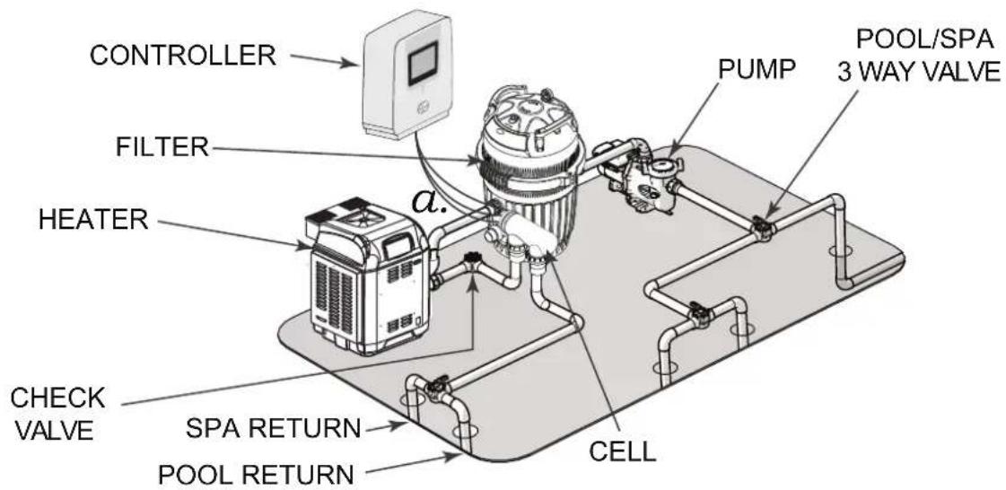
Figure 3. Typical Installation Diagram
3.1 Mounting the Controller
The Halo Chlorinator must be mounted to a wall using the steel mounting bracket supplied (see Figure 1). The following diagram shows the position of the mounting bracket, relative to the top and base of the product, which will aid in setting out the equipment area and aligning with other Halo products. If the controller is mounted to a post, a 320 mm * 320 mm flat sheet must be used.

Figure 4. Mounting dimensions
The Halo Chlorinator can be used to communicate with other Halo devices using Bluetooth so the chlorinator needs to be located less than 5 m from pH and ORP sensors and from other devices that are paired to it, e.g., Halo LITE's, Halo Xpand, or Halo Hub.
The controller should be located 1 metre above the ground to prevent splash back or sprinkler spray to the underside of the controller and should preferably be mounted out of direct sunlight.
NOTE: As insects can sometime be attracted to the warmth in a control power pack it is recommended that an insecticide surface spray is sprayed around the power pack at start up and on a regular basis to prevent any damage to the PCBs. Damage caused by insect ingress is not covered by warranty.
3.2 Pool Plumbing
The chlorinator cell must be plumbed in a position within 1.2 metres of the controller, where it is the last piece of equipment in the line, before the water returns to the pool. (Unless acid dosing is installed, in which case the acid dosing injection point is the last piece of equipment).
The cell must be installed horizontally, with the barrel unions underneath (as per the following image).
The water flow through the cell must be as shown below (also shown on the cell label).

Figure 5. Chlorinator Cell Installation
The cell kit contains 40 mm and 50 mm fittings. Generally, 50 mm pipework provides better water flow through equipment and can ensure a more efficient system.
The 4 wire cable from the chlorinator to the cell is colour coded. Unclip the endcap from the cell and plug the cell cable wires into the cell, ensuring that the colour codes are followed.
If an acid dosing pump is being installed it should be separated from the other equipment to avoid the possibility of fumes damaging the other equipment. The acid injection point (where the acid goes into the pool water) must be mounted into the pipework, after the chlorine cell and all other equipment (see acid dosing pump instructions for further information).
If pH or chlorine sensors are being installed, the sensor mounting chamber must be mounted after the filter, but before the chlorinator cell (see sensor probe instructions for more information).
3.3 Power Connections
Halo Chlorinators are provided with a 1.75 m power cable for connection to a mains outlet.
The maximum load that can be connected to the Halo Chlorinator pump outlet is 8.5 amps.
3.4 Other Connections
The following connectors are available on the Halo Chlorinator.
| CONNECTOR USE FOR | |
| RS485 AstralPool ircledR | IXi Heaters, Zodiac JXiHeaters and VSP pumps.Appendix 2 shows the wiring of the connector.Refer also to the appropriate heater or pump manual. |
| RJ12 All AstralPool | “Genus” products (Viron ircledR Connect 10, Gas Heaters, XT Pumps (Not XT BT), Connect Lite, etc.) |
| LAN Standard RJ45 style ethernet connection to home internet routers. | |
| Water temp Water temperature sensor for the filter pump water circuit.See also Appendix 1: Heater Connection Tables. | |
| Light Connection for a single AstralPool SLX or FLX light.This light must be assigned to Lighting Zone 1. | |
| pH dose Connection for the Halo pH dose pump. | |
Section 4. General Operation and Pool Chemistry
4.1 Cyanuric Acid
(Also referred to as stabiliser or sunscreen)
If a chlorine sensor is connected, cyanuric acid will suppress the ORP (chlorine) reading.
Whilst many suppliers will recommend up to 50 ppm of cyanuric acid (CyA), AstralPool recommend a maximum of 20 ppm cyanuric acid on Halo Chlorinators.
4.2 Chlorine Level/ORP
The recommended free chlorine level is 1 – 3 ppm.
If your Halo Chlorinator is not fitted with a chlorine (ORP) sensor, then the chlorine output is set in the settings menu and can be adjusted from 0 (OFF) to 8. It is recommended to run the chlorinator at level 8 for 6-8 hours per day. (4-5 hours in the off season). Generally, 2 timers are used to achieve the desired run time, e.g., 4 hours in the morning and 4 hours in the afternoon/evening. To obtain the free chlorine level of 1 – 3 ppm the chlorine output or timers can be adjusted.
If your Halo Chlorinator is fitted with a chlorine (ORP) sensor then, as above 2 timers are used to achieve 8 hours of run time, 4 hours in the morning and 4 hours in the afternoon/evening and the ORP set point should be set to achieve the 1-3 ppm level. There are many factors that affect ORP readings such as pH, salt level and cyanuric acid. Generally, an ORP level of 700 is a good starting point. If the free chlorine level is too low increase the ORP set point (reduce the setpoint to reduce the free chlorine). When making adjustments it is advisable to make small changes (e.g. 700-715) and then wait 2 days before retesting the free chlorine.
4.3 pH Level
For fibreglass pools a pH level between 7.2 and 7.4 is recommended.
For all other pools a pH level between 7.4 and 7.6 is recommended.
4.4 Total Alkalinity
Total Alkalinity between 80 and 120 ppm is recommended.
4.5 Salt Level
Never add salt to the pool skimmer box. Salt should be added gradually to the pool and brushed around until it dissolves.
A salt level of 4000 ppm is recommended. (A 50,000 litre pool will require 200 kg of salt to achieve this level.)
If the salt level drops below 3000 ppm the chlorinator will display "Low Salt" and more salt should be added to the pool.
NOTE: When the water is cold (below 16°), the chlorinator may show "Low Salt". If the salt level is actually correct, then this warning can be ignored.
Salt is not consumed by the chlorinator, however it is lost during backwashing and splashing, etc.
4.6 Ai Mode
Ai Mode is available on Halo Chlorinators that are fitted with pH and ORP sensors and a variable speed pump. In Ai mode, the Chlorinator automatically adjusts the pump speed to achieve correct filtration and sanitisation. At the start of the day the pump will run for a period at high speed and then as the ORP (chlorine) level rises it will automatically switch to medium speed. Once the ORP is within range the pump will slow to low speed and just sample the water (No Chlorine production). If the ORP drops, the pump speed will increase again and the chlorinator will start to produce chlorine again.
In Ai mode the pump speeds need to be set so that Low speed is only bringing in enough water to allow for the ORP measurement. (A Typical starting point is 1200 RPM). In this mode, no Chlorine is produced. It is just a sampling mode.
Medium speed needs to be fast enough to keep the Chlorinator Cell full of water during Chlorine production. (A Typical starting point is 2000 RPM). To conserve energy, it is important to not run the pump too fast during this period.
High speed is usually set to allow for correct skimming of the water surface and is typically close to the maximum speed of the pump (2850 RPM).
Typically timers can be set for a longer period (covering the times when the pool may be used) when using Ai mode to ensure that the Chlorine level is always optimised. (In areas where leaf debris is high, it is also good practice to have a timer to run the pump at high speed and skim the pool at the end of the day.)
4.7 Introduction to the Chlorinator Touchscreen
4.7.1 Home Screen
The default screen of the Halo Chlorinator is the "Home" screen.
The items on this screen will vary depending on the installation.
This example assumes that a variable speed pump, pH & ORP probes and a temperature sensor are fitted.

Figure 6. Halo Home Screen
The area of text at the top centre of the screen is used to describe the mode that the chlorinator is in. If ORP and/or pH probes are fitted the results will be shown in green if the results are close to the setpoint, orange if they are below and Red if they are above the setpoint.
Any system faults will also be shown in red type in this area. Clicking on the "?" will give further info on the fault. See Figure 7.

Figure 7. Halo Home Screen - Error Message
4.7.2 Navigation Buttons
| The "Pool" and "Spa" buttons are used to switch between pool and spa (if pool/spa mode is enabled). |  |
| The "Off", "Auto", and "On" buttons control the filter pump. |  |
| If a multispeed pump is fitted, then the "Low", "Medium", and "High" buttons can be used to display the pump speed whilst in auto mode and can be used to change the pump speed when in manual mode. |  |
| The "Favourites" button can be used to control your favourite modes, e.g., "spa at night" might turn the heater on and turn on your spa lights. See Section 4.7.7 for more information. |  |
| The time and the water temperature are displayed (temperature is only displayed if a suitable temperature sensing kit is installed). If the pump is off, the water temperature will be "greyed out". If a separate heater pump is being used, the temperature of the water going to the heater pump will be displayed. |  |
| If devices other than a filter pump are installed, e.g. lighting, solar, heaters, etc., then the "All Off" and "All Auto" buttons will be displayed. These buttons will control all of the devices. |  |
| The "Settings" icon is used to navigate to the settings page. |  |
4.7.3 Settings Screen
The "Settings" page is accessed via the settings icon on the home page.
The settings page is primarily used to adjust the chlorine output.
In this example the chlorine and acid levels can be adjusted using the + and - buttons (this assumes that an acid doser is fitted). If ORP and pH probes are fitted then the chlorine and pH settings can be adjusted.

Figure 8. Halo Setting Screen
4.7.4 Settings Buttons
The time and date can be adjusted by tapping the appropriate icon.
NOTE: Time and date can be updated automatically from your mobile device.
| If your chlorinator is connected to a Viron® Connect 10 controller the time and date will not be displayed. |  |
| The “Device Information” icon will display serial numbers and code versions which may help service personnel diagnose problems. |  |
| The “Maint” icon in the top ribbon on the settings page gives you access to the maintenance tab where you can perform some regular maintenance functions such as backwashing the filter and priming the acid pump, if fitted, etc. See Section 4.7.8 for more information. |  |
The “Stats” icon in the top ribbon on the settings page gives you access to the statistics of your chlorinator. Information here may help service personnel diagnose problems. On this page is also an “Events” icon which, when pressed will display a log history of recent events such as when a software update was completed or when the chlorinator may have encountered a warning message such as no water flow etc., that the chlorinator may have encountered.
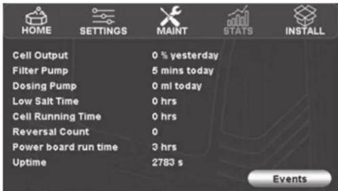
Figure 9. Halo Stats Screen
4.7.5 Timers Screen
The "Timers" screen is accessed via the top ribbon on the home page.
NOTE: If a Halo Chlorinator is connected to a Viron Connect 10 system the timers are controlled by the Viron Connect, rather than by the Halo Chlorinator, so the timers page will not appear.
The equipment timers are shown graphically in blue and the lighting timers are shown in red if lights are installed.
If a timer is currently running it will flash on and off in this screen.
The "Summer" and "Winter" buttons allow for different timers to be stored for different periods of the year and makes it easy to swap between the two choices.
To modify the time of operation of any of the timers, press the "Equipment Timers" or "Lighting Timers" button.

Figure 10. Halo Timers Main Screen
There are 8 timers available for equipment.
The timer numbers are also shown next to the line graph on the previous screen.
To modify which equipment is intended to run in each timer, to change the timers start or finish times, or to activate/deactivate the timer, press the relevant timer number in this screen.
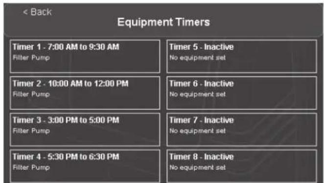
Figure 11. Halo Equipment Timers List Screen
Timer screens will vary depending on the installed equipment.
Timers 2-8 can be made active or inactive using the slider in the top right corner. Timer 1 is always active.
The start and finish times can be adjusted on this screen, as well as filter pump operation. If other equipment such as a variable speed pump is fitted, the speed can be set here as well as pool/spa, heater state, and other equipment.
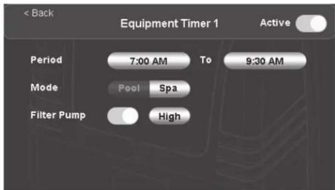
Figure 12. Halo Equipment Timer 1 Screen

Figure 13. Halo Equipment Timer 2 Screen
In some instances, items will appear "greyed out". This indicates that they cannot be adjusted on this screen, e.g., if a heater is enabled along with a variable speed pump, the pump speed may be greyed out due to the minimum required heater speed.
4.7.6 Other Equipment
If other equipment such as heaters, solar etc., are installed, the icons for these devices will appear in the top ribbon. Similarly, other devices such as cleaning pumps, water features, valves, etc., (if installed) can be found under the "OTHER" icon.
Pressing on these icons brings up controls for this equipment.

Figure 14. Halo Other Equipment Main Screen
4.7.7 Favourites
The Favourites page is accessed via the Favourites icon on the Home Page.
Favourites let you manually control your pool in a simple manner, e.g., having a spa at night with the lights on.
Once you have finished with your favourites you need to press "All Auto" to go back to automatic mode. See Figure 14.

Figure 15. Halo Favorites Screen
To activate a favourite, press the relevant favourite button.
To edit the function of the favourite button, press the edit icon next to it.
This example below assumes that a pool and spa are installed.

Figure 16. Halo Favorites Edit List Screen
Any equipment that is installed can be configured to come on when the favourite is pressed.
Some functions may be "greyed out", e.g., "Cleaning Pump" may be greyed out in spa mode if the cleaning interlock is enabled during installation.
To edit the name of the favourite, press the edit icon next to the name. ("Pool" and "Spa" favourite names can't be edited.)
The pool and spa favourites in this menu also relate to the pool and spa buttons on the home page, so if you edit the function of either of these favourites, the pool and spa buttons on the home page will also be affected.
4.7.8 Maintenance Screen
The "Maint" page is accessed via the settings icon on the Home page.
The "Maint" page is used to perform simple maintenance operations on the pool.
In this example the pool has acid dosing as well as chemical sensing probes. (Other installations will have less options.)

Figure 17. Halo Maintenance Screen
Sanitise
Options here are:
- Sanitise until first timer tomorrow
- If this is selected, the chlorinator will run the filter pump and chlorinate until after the first filter timer period the next day has finished. The chlorinator will then revert to "Auto" mode.
- Filter for period
- If this is selected you get the option to run the filter pump for a period of up to 24 hours. The chlorinator will NOT produce chlorine during this period. (This setting is often used to "start up" a pool, add salt etc and balance the water chemistry prior to starting to chlorinate.)
Backwash
- This button allows you to backwash your filter for between 1 and 15 minutes. During this period the chlorinator doesn't produce chlorine.
Calibrate Sensors
- This button allows you to calibrate your pH or chlorine sensors. There is an option to "Run the pump during calibration".
- If the sensors are still in place in the pool pipework, then the pump should be run during calibration. To ensure that the pool water is thoroughly mixed, it is advisable to run the filter pump for at least an hour before performing a calibration.
-
If the sensors have been removed and placed into calibration fluid, then the pump should not be run during calibration.
-
For pH sensors, if you notice that your pH measurement is slightly different from your pool shop's measurement, or a test strip, etc., then you can use the "Run the pump during calibration" option and adjust the sensor reading up or down to match the other reading. Alternatively, you can choose to not run the pump during calibration and use pH calibration fluid to calibrate the pH probe. (Calibration fluid is available from AstralPool® dealers.)
- For ORP sensors, the differences in pool chemistry (salt level, pH, cyanuric acid "stabiliser", hardness, etc.) makes comparisons between the ORP level and measured free chlorine (chlorine ppm) levels extremely difficult. Because of this, calibrating the ORP sensor using the pool water is of little value, so if you wish to calibrate (or check the
performance) of the ORP sensor then the "Run the pump during calibration" option should not be used and the ORP sensor should be removed from the pipework and calibrated using calibration fluid. (Calibration fluid is available from AstralPool® dealers.)
Manual Acid Prime
- This button allows you to run the acid dosing pump in manual mode to fill all of the tubing with acid after replacing an empty acid drum. In this mode the dosing pump will run for 30 seconds. If this time is insufficient, it can be run again. This mode can be cancelled at any time.
Acid Dosing Off
- This button allows you to turn acid dosing off either indefinitely or for a period between 1 minute and 24 hours. For example, if you have run out of acid you may wish to turn the acid dosing pump off indefinitely (until you purchase more acid), or if you have added sodium bicarbonate to increase alkalinity, you may wish to disable dosing for 24 hours. (After this period the dosing pump will resume normal operation.)
Manual Acid Dose
- This button allows you to choose to dose a specific amount of acid into the pool. The filter pump will start automatically during this manual dosing. You can select if you want the filter pump to be on, off or in auto mode at the end of the dosing period.
4.7.9 Introduction to the Install Screen
The "Install" page is accessed via the settings icon on the Home Page.
The "Install" page is used to configure the chlorinator and allow app access.
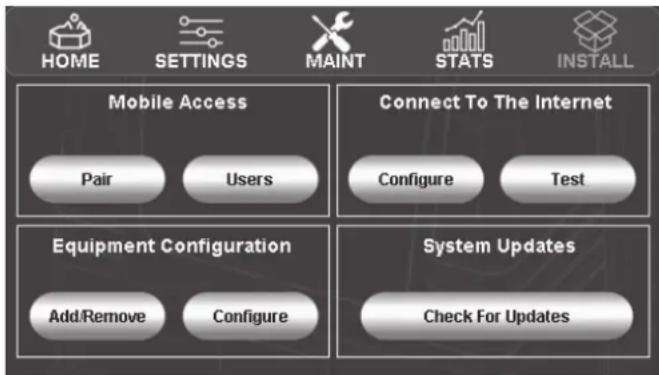
Figure 18. Halo Install Screen
The "Mobile Access" area assists with setting up the Halo ChlorGo app.
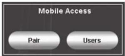
The "Mobile Access" area has two functions.
1. Pairing
a. Start pairing
This will allow the phone application to pair with the chlorinator.
b. Unpair
By pressing this button, all previously set up LAN and Bluetooth connections will no longer have access.
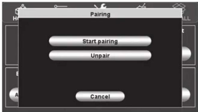
Figure 19. Halo Pairing Screen
2. Users

BT connection

Remote connection

LAN connection
a. Connection states
Above the "Users" button the current state of the mobile connection will be shown.
... = A Bluetooth connection is starting
Blue = A Bluetooth connection established
Green = LAN connection established
Yellow = Remote connection established
b. Users
Within the "Users" menu a list of current remote users can be seen.
To stop a user from accessing the Chlorinator remotely, press the "Remove" button next to their name in the Users list. See Figure 20.
If a remote user is currently connected, a yellow dot will appear against their name.
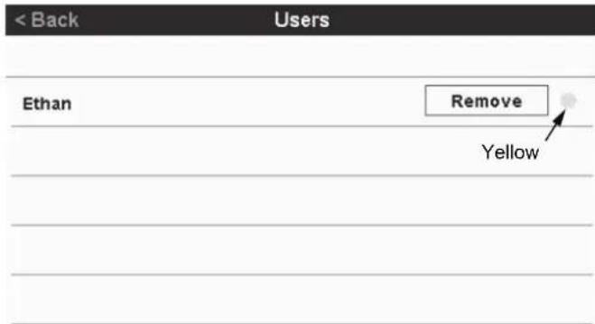
Figure 20. Halo Users Screen
Remote user currently connected
The "Connect to the Internet" area allows you to connect the chlorinator to the internet. This allows you to update the chlorinator software if required and to control the chlorinator remotely using the Halo ChlorGo app.

The "Test" button allows you to test the current internet connection and will show a number of tests. See Section 9 for more information.
NOTE: If you have turned the power off to your chlorinator, you should wait for 1 minute before testing to ensure that all of the connections are re-established.

Figure 21. Halo Test Internet Connection Screen
The "Configure" button shows the existing internet connection details (if any) and allows you to configure/change the chlorinator to use either WiFi or ethernet. (WiFi uses the onboard antenna, ethernet uses the LAN connection.) If any Internet connection test fails, see Section 9 for more information about Troubleshooting.
This example shows a WiFi Connection.

Figure 22. Halo Configure WiFi Screen
If an ethernet cable is connected, the internet connection is automatic.
Otherwise, when "Configure WiFi" is pressed a list of available WiFi networks is shown.
At this point you can either select a WiFi network to join or connect using WPS.
If your home internet connection supports WPS, follow the routers WPS instructions and then press the "Connect with WPS" button.
Otherwise select the WiFi network that you wish to join and enter the password for that network.
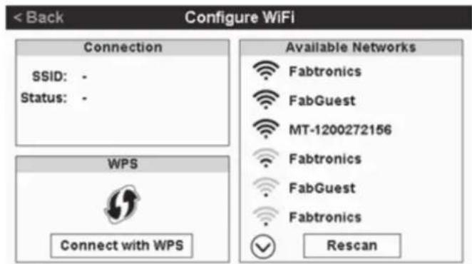
Figure 23. Halo Configure WiFi - Networks Screen
The "System Updates" button allows you to update the software of the chlorinator. To use this feature the chlorinator must be connected to the internet as above.
The "Equipment Configuration" area is used by the installer to configure the chlorinator.

4.8 Setup Required to Use the Halo ChlorGo App
The Halo ChlorGo app can connect to the Halo Chlorinator using 2 different methods.
Bluetooth connection, which allows short range connection to the chlorinator is available on all Halo Chlorinators.
Internet connection, which allows connection wherever the internet is available, through your local WiFi or mobile service. For this process the Halo Chlorinator needs to be connected to the internet as described previously.
The Halo ChlorGo app automatically determines which connection method is appropriate.
The app can be loaded onto multiple mobile devices, however you can only connect one device at a time.
To pair your mobile device to the Halo Chlorinator for the first time:
- Download the Halo ChlorGo app from the appropriate app store:

- Enable Bluetooth and Location Services before connecting the Halo ChlorGo to your mobile device.
- Open the Halo ChlorGo app.
- Navigate to the install page.
- Start pairing on the chlorinator.
- Press the "+" button on the app to add your new device.
- Follow pairing instruction on the app.
LED Colors: Blue-Green

Figure 24. Halo ChlorGo Mobile App Screen
Section 5. Chlorinator Configuration and Setup
The chlorinator comes configured to use a single speed pump, no temperature sensor and a "Cell Reversal Period" of 4 hours. If this setup is acceptable, then the only other setup that is required is to set the pool and/or spa volumes.
To change the above settings, or to set up the Halo Chlorinator to include multi speed pumps, pH and ORP sensors or a pH dosing pump follow the steps below.
The "Install" page is accessed via the settings icon on the home page.
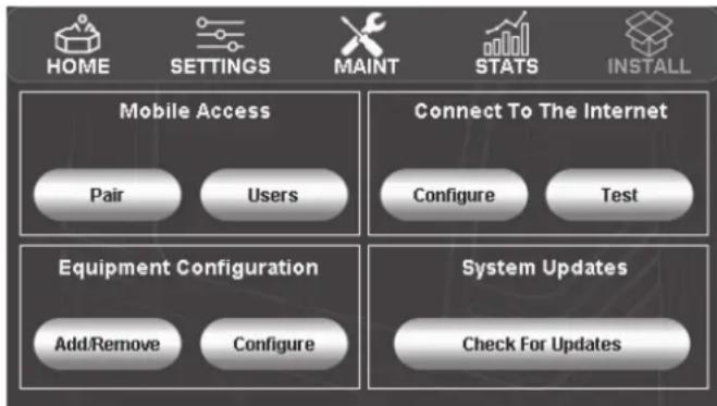
Figure 25. Halo Install Main Screen
The Halo Chlorinator can be set up to be pool only, spa only or pool and spa. To set this, and the water volumes, press "Configure" in the "Equipment Configuration" section above and then select "Pool/ Spa". On this page you can use the slider to select pool and/or spa and then use the "+" and "-" buttons to set the water volume.
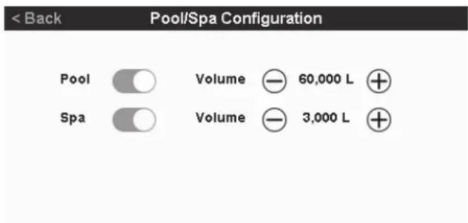
Figure 26. Halo Pool/Spa Configuration Screen
If you need to adjust the "Cell reversal period" or wish to install a pH dosing pump (without a pH Probe) or have a temperature sensor attached to the Halo Chlorinator, press "Configure" in the "Equipment Configuration" section above, select "Chlorinator".
The “+” and “-” buttons can be used to set “Cell Reversal Period” and the sliders can be used to enable the other features.

Figure 27. Halo Chlorinator Configuration Screen
NOTE: Installing a pH sensor automatically enables the acid pump.
Installing an XT pump using an RJ12 cable or a Zodiac® VSP using RS485 is automatic. Just plug the pump and communications cables in and turn the pump on from the chlorinator. (You will still need to set each pump speed as per the section below though.)
To install an XT-BT pump, press "Add/Remove" in the "Equipment Configuration" section, then select "Filter Pump" and then "Astral Variable Speed (Wireless)".

Figure 28. Halo Select Filter Pump Type Screen
To configure the variable speed pump press "Configure" in the "Equipment Configuration" section and then select the type of variable speed pump that you have installed.

Figure 29. Halo Pump Configuration Screen
NOTE: If you have installed an AstralPool® Variable Speed (wired) pump, you cannot set the RPM levels for Low, Medium and High speed on the chlorinator.
If you have installed an AstralPool Variable Speed (wireless) or Zodiac Variable speed pump, then you can set the Low, Medium, High and priming speeds, along with the priming time.
(On AstralPool® Variable Speed pumps, priming speed can be set to max which drives the pump at a higher speed than normal to facilitate quicker priming.)
The priming time can also be adjusted on this page.
The pump flow check feature can be disabled on this page if required (not advisable), and a "Cleaning Interlock" can be turned on if an infloor cleaning pump is installed. This interlock stops the cleaning pump from coming on whilst in spa mode and also enforces that the filter pump must be on with the cleaning pump.
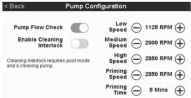
Figure 30. Halo Pump Configuration Flow Check Screen
One pH sensor can be fitted and if a pH sensor is fitted, then a Gold Tip chlorine sensor can also be fitted. To add a sensor press "Add/Remove" in the "Equipment Configuration" section above and then select "pH Sensor". To pair with the sensor, press and release the "pair" button on the top of the sensor. Connection is automatic. A Gold Tip chlorine sensor can then also be added in a similar manner.
If Ai mode is required (pH and ORP probes and variable speed pump must already be installed), return to the "Equipment Configuration" section on the Install page, press "Configure", choose "Chlorinator" and slide the Ai enabled slider to the right.
This will allow timers to select Ai mode for the pump speed. Enabling Ai in the timer will allow the chlorinator to decide the required pump speed automatically.

Figure 31. Halo Chlorination Configuration Example Screen
5.1 Connecting Other Devices to a Halo Chlorinator
See below for some info on other Halo devices that can be connected to a Halo Chlorinator. (Refer to each device's instructions for installation instructions.)
Halo pH Doser
One Halo pH doser can be connected to a Halo Chlorinator through the "pH dose" connector. This connector powers the dose unit and no other electrical connections are required.
The pH doser kit contains the required tubing and connectors along with installation instructions.
Halo LITE2 and Halo LITE4
A total of 2 Halo LITE's can be connected wirelessly to a Halo Chlorinator. (2 LITE2's or 2 LITE4's or 1 of each). If a Halo LITE 4 is connected wirelessly, up to 4 more Halo LITE 4's can be connected to it via RJ12 cables.
Halo Hub and Halo Xpand
Only 1 Halo Hub can be connected to a Halo Chlorinator.
If a Halo Hub is connected, then you can also connect a Halo Xpand.
If a Halo Hub is not connected, then you can connect up to 2 Halo Xpands.
The Halo Hubs and Xpands connect wirelessly to the Halo Chlorinator.
Halo Chlorinators can also connect to Viron® Connect 10 systems.
This connection is through traditional RJ12 cables.
Installation of the chlorinator in this application is similar to the above installation instructions (including chemical sensing probes, pH doser and Halo LITE's) however, as in other Viron Connect 10 systems, the timer functionality is controlled through the Connect 10.
Halo Hubs and Xpands cannot be used in Viron Connect 10 systems.
An AstralPool Connect LITE may also be connected to a Halo Chlorinator via RJ12 cables.
Appendix 1 gives information on connecting heaters to Halo systems.
Section 6. Control Using the Halo Chlorinator
It is recommended to run the chlorinator for 6-8 hours (or longer if using Ai mode) per day during summer (4-5 hours in the off season).
To set the timers, press "Timers" in the top ribbon of the home page.
Generally, 2 timers are used to achieve the desired run time e.g., 4 hours in the morning and 4 hours in the afternoon/evening. If a variable speed pump is installed however it is generally more efficient to run at medium speed for the majority of the timer period, so in this case you may have timer 1 for 1 hour on high speed (to skim leaves off the pool), timer 2 for 3 hours on medium speed, and timer 3 for 4 hours on medium speed.
The home page also gives information on the state of the chlorinator. (In this example a variable speed pump is fitted, along with chlorine and pH sensors.)
The first line of the display shows the state of the filter pump, e.g., in auto mode, "Sanitising" shows that the filter pump is running, "Standby" indicates that the filter pump is not running, but the next timer will turn it on again.

Figure 32. Halo Main Screen (In Operation)
Control of the chlorine level in the pool is usually a combination of the length of time that the chlorinator is running for and the chlorine level setting. Other variables such as water temperature, sunlight, pH and the number of people using the pool will affect the amount of chlorine used.
Any adjustments to chlorine and pH levels may take 2 or more days to take effect. Sometimes, e.g., at the start of summer, large changes to the settings are required but where possible a number of small changes to settings will yield a more stable result.
The following information shows the "Settings" screen for various installations.
1 - Standard chlorinator
The amount of chlorine produced is controlled by the "Chlorine Level" slider. In pool mode this can be adjusted from 0 to 8 and in spa mode the adjustment is 0 to 4. (Pool and spa settings are independent of each other.)
NOTE: 0 produces no chlorine, i.e. filtration only

Figure 33. Halo Pool Chlorine Level Screen
2 -Standard chlorinator with pH dosing
As above the amount of chlorine produced is controlled by the "Chlorine Level" slider. The "Acid Level" slider is used to estimate how much acid needs to be added. Generally, level 5 is a good starting point, however it can be adjusted to increase or reduce the amount of acid dispensed. Acid dosing can be disabled for a period, if required, using the "Maint" icon (to add this feature order part number 20389).
NOTE: Adding more acid will lower the pH level, less acid increases the pH level.

Figure 34. Halo Pool Chlorine and Acid Level Screen
3 -Standard chlorinator with pH sensing
As in case 1 above, the amount of chlorine produced is controlled by the "Chlorine Level" slider. And the pH is controlled by setting the pH level on the settings page. The actual pH will be displayed on the home page. Previous pH setting will be displayed when the pump is off (to add this feature order part number 20390).

Figure 35. Halo Pool Chlorine and pH Setpoint Screen
4 -Standard chlorinator with chlorine and pH sensing
In this set up, the chlorine level is set by adjusting the ORP level (higher ORP => higher chlorine level). Remember that it can take several days for your adjustments to be seen in the pool.
Using the "Stats" icon will show the % cell output yesterday. This is useful when determining the filter pump timers settings. Generally if this figure is above 80%, you should increase your filter pump time (to add this feature order part number 20391).
The pH control is as above in case 3.

Figure 36. Halo ORP and pH Setpoint Screen
Section 7. Control Using the Halo ChlorGo App
See section 4.8 for app installation instructions.
Control using the Halo ChlorGo app is essentially the same as from the chlorinator, however, the icons are situated on the bottom ribbon rather than the top.
Some maintenance functions aren't permitted from the app as you need to be in close control of the chlorinator to perform them.
No installation functions are available from the app.
On the "Settings" page of the app there is a setting for date & time. If this is selected then there is an option to update the time and date automatically. If automatic update is selected, then every time that you connect to the chlorinator via Bluetooth or local connection, the time will be updated.
Some WiFi routers (particularly in commercial properties), are set so to block "UDP" communications. If this is the case, then you won't be able to communicate with your chlorinator from these sites using WiFi. If you disable WiFi on your phone, then you should be able to communicate with your chlorinator through your phone's internet connection.
Section 8. Regular Maintenance
The Halo Controller is vented to allow the electronics to cool during extreme warm temperatures. During cooler months, ants and other insects can be attracted to the warm, dry environment inside the enclosure.
Turn the mains power off to the controller.
Spray a surface insecticide on the surfaces surrounding the controller.
Repeat every three months or as necessary.
Section 9. Troubleshooting
9.1 Internet Connectivity
No internet connection present.
Check ethernet cable or enter WiFi credentials.

Figure 37. Halo Internet Connectivity Error Message Screen
WiFi connected or Ethernet connected
This will be ticked if a connection is detected.
Local network address assigned
This shows that an IP address has assigned by the router.
Update server connection
The software update server can be contacted by the chlorinator.
This will allow software updates to be uploaded if required.
Remote server connection
The remote connection server can be contacted by the chlorinator.
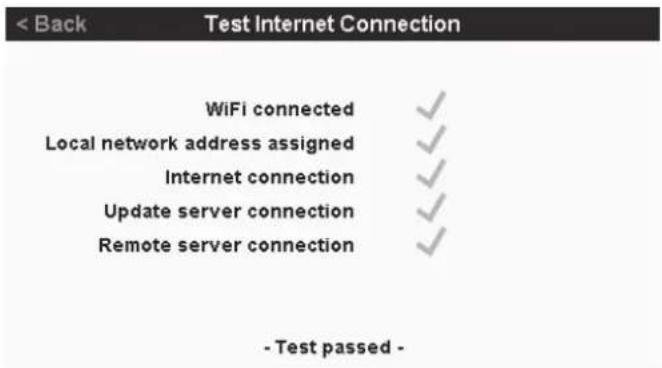
Figure 38. Halo Test Internet Connection Status Screen -WiFi

Figure 39. Halo Test Internet Connection - Passed Screen - Ethernet
Section 10. Appendices
10.1 Appendix 1: Heater Connection Tables
Heater Connection Table – Heater uses the filter pump
| HEATER TYPE | DEVICE TO CONNECT TO CONNECTOR | EXTERNAL TEMPERATURE SENSOR REQUIRED? NOTES | ||
| AstralPool® “Genus” style Heaters | Halo Chlor RJ12 No | |||
| AstralPool IXi Heaters Halo Chlor | RS485 No | |||
| Zodiac® JXi Heaters Halo Chlor | RS485 No | |||
| AstralPool Viron Heatpumps | Halo Chlor OR | RJ12 No | Requires “13709 Heatpump Interface” module. | |
| Halo Hub | RJ45 No | Connects directly to Hub using RJ45 cable. | ||
| Other heaters and heatpumps using “T-Stat” or other low voltage control | Halo Hub | Heater | Yes Temp sensor plugs into Halo Chlorinator. | See Halo Hub manual for connection details. |
| Other heaters and heatpumps using 240 volt mains control | Halo Hub OR Halo Xpand | GPO1 | Yes Temp sensor plugs into Halo Chlorinator. | See Halo Hub or Xpand manual for connection details. See also Note 1. |
Heater Connection Table – Heater doesn't use the filter pump
| HEATER TYPE | DEVICE TO CONNECT TO | CONNECTOR | EXTERNAL TEMPERATURE SENSOR REQUIRED? NOTES | |
| AstralPool “Genus” style Heaters | Halo Chlor | RJ12 | No | |
| AstralPool IXi Heaters | Halo Chlor | RS485 | No | |
| Zodiac JXi Heaters | Halo Chlor | RS485 | No | |
| AstralPool Viron Heatpumps | Halo Chlor OR | RJ12 | No | Requires “13709 Heatpump Interface” module. |
| Halo Hub | RJ45 | No | Connects directly to Hub using RJ45 cable. | |
| Other heaters and heatpumps using “T-Stat” or other low voltage control | Halo Hub | Heater | Yes Temp sensor plugs into Halo Hub | See Halo Hub manual for connection details. |
| Other heaters and heatpumps using 240 volt mains control | Halo Hub OR Halo Xpand | GPO1 | Yes Temp sensor plugs into Halo Hub/Xpand | See Halo Hub/Xpand manual for connection details.See also Note 1.See also Note 2. |
NOTE 1: If GPO1 is being used to power the heater, care needs to be taken to ensure that the total power from GPO1 and GPO2 doesn't exceed the devices limits.
A remotely mounted, external 240 volt contactor can be driven by GPO1 if higher currents (or 3 phase power) is required.
NOTE 2: If using a Halo Hub or Halo Xpand, the temperature sensor must be plugged into the Halo Hub or Halo Xpand that is supplying power to the heater pump.
10.2 Appendix 2: Zodiac® RS485 connection
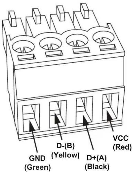
NOTE: This color sequence will match RS485 cables provided with Zodiac AquaLink systems or the Zodiac VSP Pump.
Figure 40. Halo RS485 Connector
NOTES

H0725000
Fluidra Group Australia Pty Ltd
219 Woodpark Road
Smithfield NSW 2164, Australia
1 300 186 875
www.astralpool.com.au
- HALO® CHLORINATOR
- WARNING
- EQUIPMENT INFORMATION RECORD
- Section 1. Important Safety Instructions ....4
- Section 2. System Overview ....5
- Section 3. Installation....6
- Section 4. General Operation and Pool Chemistry....7
- Setup Required to Use the Halo ChlorGo App 14
- Section 5. Chlorinator Configuration and Setup....15
- Section 6. Control Using the Halo Chlorinator....17
- Section 7. Control Using the Halo ChlorGo App ....19
- Section 8. Regular Maintenance ....19
- Section 9. Troubleshooting....20
- Section 10. Appendices....21
- Section 1. Important Safety Instructions
- READ AND FOLLOW ALL INSTRUCTIONS
- Section 2. System Overview
- Contents of this Kit
- View of the Base of the Unit
- Mounting the Controller
- Pool Plumbing
- Power Connections
- Other Connections
- Section 4. General Operation and Pool Chemistry
- Cyanuric Acid
- Chlorine Level/ORP
- pH Level
- Total Alkalinity
- Salt Level
- Ai Mode
- Introduction to the Chlorinator Touchscreen
- Home Screen
- Navigation Buttons
- Settings Screen
- Settings Buttons
- Timers Screen
- Other Equipment
- Favourites
- Maintenance Screen
- Sanitise
- Backwash
- Calibrate Sensors
- Manual Acid Prime
- Acid Dosing Off
- Manual Acid Dose
- Introduction to the Install Screen
- Pairing
- Users
- BT connection
- Remote connection
- LAN connection
- b. Users
- Setup Required to Use the Halo ChlorGo App
- Section 5. Chlorinator Configuration and Setup
- Connecting Other Devices to a Halo Chlorinator
- Halo pH Doser
- Halo LITE2 and Halo LITE4
- Halo Hub and Halo Xpand
- Section 6. Control Using the Halo Chlorinator
- - Standard chlorinator
- -Standard chlorinator with pH dosing
- -Standard chlorinator with pH sensing
- -Standard chlorinator with chlorine and pH sensing
- Section 7. Control Using the Halo ChlorGo App
- Section 8. Regular Maintenance
- Section 9. Troubleshooting
- Internet Connectivity
- WiFi connected or Ethernet connected
- Local network address assigned
- Update server connection
- Remote server connection
- Section 10. Appendices
- Appendix 1: Heater Connection Tables
- Appendix 2: Zodiac® RS485 connection
- NOTES
Brand : ASTRALPOOL
Model : Halo Chlor 35
Category : Water filter