
WQ401 - Portable device YSI - Free user manual and instructions
Find the device manual for free WQ401 YSI in PDF.


| Type de produit | Portable Water Quality Meter |
| Marque | YSI |
| Modèle | WQ401 |
| Dimensions (approx.) | 200 mm x 80 mm x 40 mm |
| Poids (avec piles) | 500 g |
| Alimentation | 4 piles AA (type LR6) ou adaptateur secteur (optionnel) |
| Autonomie des piles | Jusqu'à 40 heures d'utilisation continue |
| Affichage | Écran LCD rétroéclairé avec graphiques |
| Paramètres mesurés | Température, Conductivité, pH, Oxygène dissous, Turbidité |
| Gamme de mesure - Température | -5°C à 50°C (précision ±0.1°C) |
| Gamme de mesure - Conductivité | 0 à 200 mS/cm (précision ±0.5%) |
| Gamme de mesure - pH | 0 à 14 unités pH (précision ±0.02) |
| Gamme de mesure - Oxygène dissous | 0 à 20 mg/L (précision ±0.1 mg/L) |
| Mémoire interne | Enregistrement jusqu'à 10 000 mesures avec horodatage |
| Interface | USB 2.0 pour transfert de données et mise à jour firmware |
| Protection | Indice IP67 (étanche immersion 1 m durant 30 min) |
| Fonctions spéciales | Calibration automatique, compensation de température, alarmes |
| Entretien | Nettoyage des capteurs à l'eau distillée après chaque usage |
| Réparabilité | Capteurs remplaçables sans outil, assistance technique YSI |
| Contenu du coffret | Appareil, capteurs, 4 piles AA, câble USB, mallette de transport, manuel |
Frequently Asked Questions - WQ401 YSI
User questions about WQ401 YSI
0 question about this device. Answer the ones you know or ask your own.
Ask a new question about this device
Download the instructions for your Portable device in PDF format for free! Find your manual WQ401 - YSI and take your electronic device back in hand. On this page are published all the documents necessary for the use of your device. WQ401 by YSI.
USER MANUAL WQ401 YSI
natural_image
Simple black-and-white icon of a stylized storefront with wavy windows, enclosed in a rounded square border (no text or symbols)Global Water
Instrumentation, Inc.
11390 Amalgam Way
Gold River, CA 95670
T: 800-876-1172
Int'l: (916) 638-3429, F: (916) 638-3270
Temperature Sensor: WQ101
pH Sensor: WQ201
Conductivity Sensor: WQ301
Dissolved Oxygen Sensor: WQ401
ORP/Redox: WQ600

Global Water
800-876-1172 • globalw.com
Congratulations on your purchase of Global Water's Water Quality Sensors. This instrument has been quality tested and approved for providing accurate and reliable measurements. We are confident that you will find the sensor to be a valuable asset for your application. Should you require assistance, our technical staff will be happy to help.
Table of Contents
| I. | Checklist | ● | ● | ● | ● | ● | ● | Page | 3 |
| II. | Inspection | ● | ● | ● | ● | ● | 3 | ||
| III. | General Sensor Installation | ● | ● | ● | ● | 4 | |||
| IV. | Temperature Sensor | ● | ● | ● | ● | 6 | |||
| V. | pH Sensor | ● | ● | ● | ● | ● | ● | 7 | |
| VI. | Conductivity Sensor | ● | ● | ● | ● | 10 | |||
| VII. | Dissolved Oxygen | ● | ● | ● | ● | ● | 12 | ||
| VIII. | ORP/Redox | ● | ● | ● | ● | ● | ● | 14 | |
| IX. | Maintenance | ● | ● | ● | ● | ● | 16 | ||
| X. | Troubleshooting | ● | ● | ● | ● | ● | 17 | ||
| XI. | Warranty | ● | ● | ● | ● | ● | ● | 18 | |
| XII. | Appendix A: Calibration Procedures | ● | ● | ● | ● | 19 | |||
| XIII. | Appendix B: 2 Wire Sensor Measurement Diagram | ● | ● | 24 | |||||
| XIV. | Appendix C: 3 Wire Sensor Measurement Diagram | ● | ● | 25 | |||||
| XV. | CE Certifications | ● | ● | ● | ● | ● | 26 | ||
* Copyright © Global Water Instrumentation, Inc. 2008

Global Water
800-876-1172 • globalw.com
I. Sensor Checklist
a. Water Quality Sensor
b. Water Quality Sensor Manual
II. Inspection
a. Your water quality sensor was carefully inspected and certified by our Quality Assurance Team before shipping. If any damage has occurred during shipping, please notify Global Water Instrumentation, Inc. and file a claim with the carrier involved.
Use the checklist to ensure that you have received everything needed to operate the water quality sensor.

Global Water
800-876-1172 • globalw.com
III. Sensor Installation
General
a. Water quality sensors have many applications and therefore many installation options. All the sensors are fully submersible and may be suspended by their waterproof cables in the water to be monitored.
b. Do not install the water quality sensor in applications that contain solvents. Over time, many solvents can deteriorate the cable and the sensing element.
c. Install your water quality sensor so that it is easily accessible for calibration purposes. You may need to remove and reinstall it in the future, so plan ahead!
d. The sensors will not function correctly if mud, silt, leaves, or garbage buries them. The pH, Dissolved Oxygen, and ORP/Redox sensors will fail if they are left out of the water for extended periods of time. Install the sensor in a way that will avoid these conditions.
e. All Global Water water quality sensors produce a 4-19 mA output signal. 4-19 mA is an industrial standard signal for process control monitoring. Most PLCs (Programmable Logic Controller), RTUs (Remote Telemetry Unit), and data acquisition systems accept this signal directly. If the system only accepts voltage signals, the sensor output must be converted to a voltage signal by reading the voltage across a precision resistor in series with the signal wire. Since Ohms Law states that V = IR, if the 4-19 mA signal is dropped across a 250 ohm resistor, the output will be 1 to 4.75 volts DC. If the 4-19 mA signal is dropped across a 125 ohm resistor, the output will be halved to 0.5 to 2.375 VDC. The 4-19 Ma signal wire is connected to the datalogger voltage input terminal. The resistor is placed between this input and the ground terminal of the datalogger's battery. The power (or voltage to the sensor) must be connected to positive battery terminal of the datalogger.

Global Water
800-876-1172 • globalw.com
f. The sensors may be pulsed on or turned on by the logging system prior to taking a reading. Use a warm up time appropriate to the water quality sensor you are using to assure that the sensor is fully on. The sensors can run continuously for real time applications. Each sensor draws between 4 and 19mA depending on whether the sensor is reading at the minimum or maximum of its range.
Groundwater
g. Sensors may be suspended in 2" monitoring wells near the well screen. Several sensors may be suspended in the same well by staggering the sensors one foot apart.
Surface Water
h. Sensors may be submerged at the monitoring point and hung from their cables. It is recommended to protect the sensors inside a 4" PVC drainpipe that will act as a protective stilling well. Put a cap on the bottom end of the pipe to allow easy water flow past the sensors. Drop the sensor until it touches the bottom of the stilling well and then pull it up slightly and secure the cable.

Global Water
800-876-1172 • globalw.com
IV. Temperature Sensor
a. Temperature sensor specifications.
Output: 4-19mA
Range: -50^ C to +50^ C
Accuracy: ±0.2^ F or ±0.1^ C
Operating Voltage: 10-36VDC
Current Draw: Same as sensor output.
Warm Up Time: 5 seconds minimum
Operating Temperature: -50^ to +100^
Size of Probe: 3/4" diameter x 4 1/2" long
Weight: 1/2 lb.
b. The sensor is a two-wire sensor using the red wire for power and the black wire for the output signal. Warning: Always connect the sensor with the power turned off.
c. The temperature sensor may be stored without any special provisions. Place the sensor inside a bag to keep the sensor clean and store on a shelf or hang it on a wall.
d. To check the temperature sensor calibration you will need:
1 thermometer
3 containers of water
1 power supply
1 current meter
Connecting wires as necessary
Connect the sensor to the power supply and current meter in the following way. Attach the black wire to the positive input of the current meter. Connect the ground terminal of the power supply to the ground of the current meter. Attach the red wire to the positive terminal of the power supply. See Appendix B. Warning: Always connect the sensor with the power turned off.
See Appendix A for the temperature calibration worksheet.

Global Water
800-876-1172 • globalw.com
V. pH Sensor
a. pH sensor specifications.
Output: 4-19mA
Range: 0-14 pH
Accuracy: 2% of full scale
Operating Voltage: 10-36VDC
Current Draw: 16.6 mA plus sensor output
Warm Up Time: 3 seconds minimum
Operating Temperature: -5^ to +55^ C
Pressure Rating: 0-100 psi
Size of Probe: 1 1/4" diameter x 10" long
Weight: 1 lb.
b. The sensing element is covered with a protective cap while at the Global Water facility to prevent the sensor from becoming damaged. This cap must be removed prior to sensor installation or the readings will be in error. To remove the cap, remove the protective shield and remove the rubber cap covering the sensing element. Replace the protective shield. Note: Save the cap for future use.
c. This sensor has a removable sensing electrode. If the sensor is reading incorrectly, after following the basic maintenance steps, the electrode should be removed and the metal contacts cleaned. If this does not improve the sensor's results the electrode should be replaced. To remove the sensing electrode loosen the set screw holding the sensor shield and remove the shield from the sensor. Unscrew the sensing electrode from the sensor housing. Clean the metal contacts of the electrode with a clean cloth. If the electrode is replaced with a new electrode the sensor must be recalibrated to work correctly.
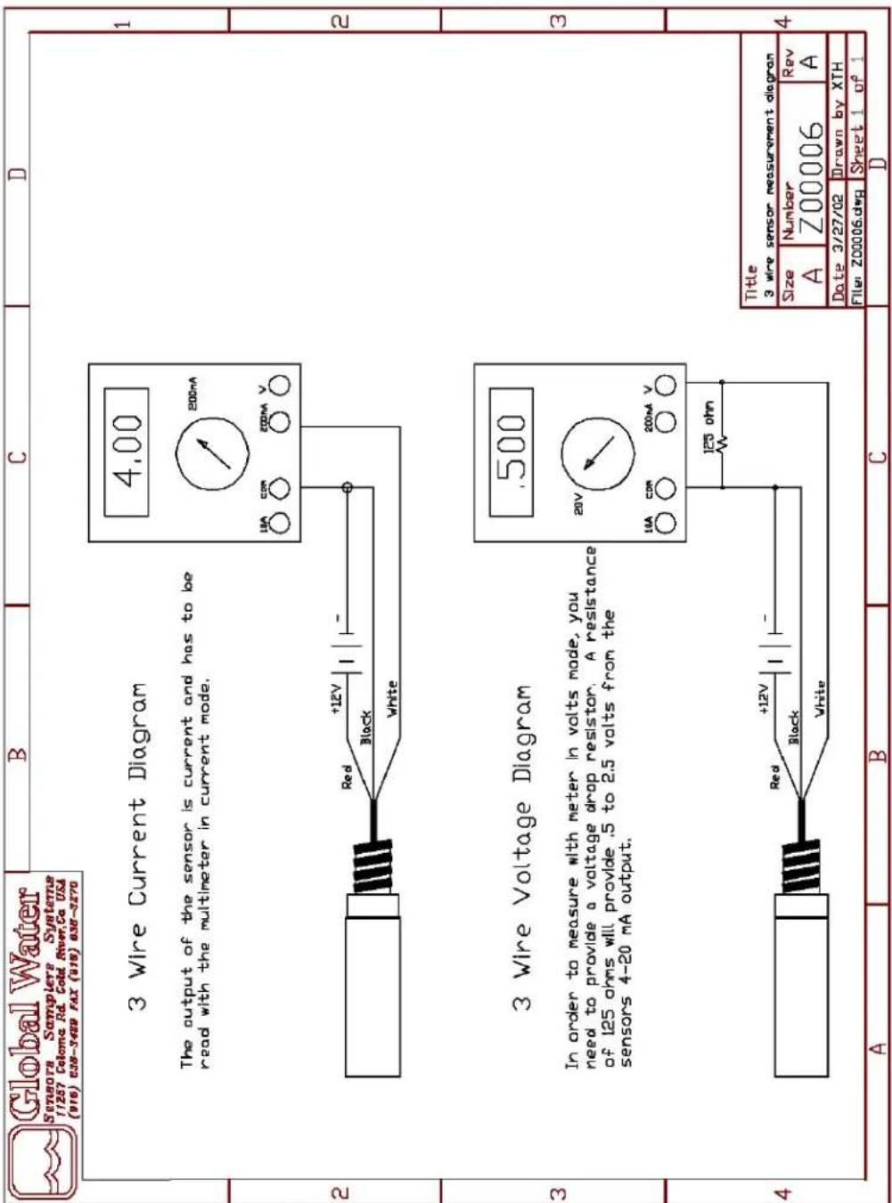
d. The pH sensor is a three-wire sensor. Three wire sensors use the red wire for positive voltage, the white wire for the output signal, and the black wire for ground. Warning: Always connect the sensor with the power turned off.

Global Water
800-876-1172 • globalw.com
e. The pH sensor must be stored where the sensing element remains wet or the sensing element will be damaged. It can be stored in a container of clean water or a wet sponge can be placed inside the protective cap shipped with the sensor. Place the cap over the sensing element to keep it wet. The sensor can then be stored on a shelf or hung on a wall.
f. The pH value of a substance is directly related to the ratio of hydrogen ion (H+) and Hydroxyl ion (OH-) concentrations. If H+ is greater than OH-, the solution is acidic, i.e., the pH value falls in the 0 to 7 range. If the OH- is greater than the H+, the material is basic with a pH value in the 7 to 14 range. If equal amounts of H+ and OH- ions are present, the material is neutral with a pH value of 7.
The pH electrode can be thought of as a battery whose voltage changes as the pH of the solution in which it is inserted changes. It consists of two basic parts: 1) a Hydrogen ion-sensitive glass bulb, and 2) a reference electrode. The special glass of the sensitive bulb has the ability to pass H+ i.e., it is said to be H+ sensitive. This ability allows the H+ inside the bulb to be compared to the H+ outside of the bulb, and a voltage to be developed that is related to the difference. The bulb then is a half-cell that needs a reference voltage in order to function.
The voltage produced by the complete probe is a linear function of pH, generally about 60 mV per pH unit. For example, at 7.00 pH the probe produces zero volts while at 6.00 pH it produces +60 mV. If the voltage had been negative it would indicate that the solution had a value of 8.00 pH.
A buffer solution is a solution with a well-defined pH value and has the ability to resist changes in pH. These characteristics are well suited to the standardization of pH measuring systems. Buffers are available in a wide range of pH values and come either in pre-mixed liquid form or as convenient dry powder capsules. When selecting buffers for use with your particular system, a value should be chosen nearest to that of the sample being measured.

Global Water
800-876-1172 • globalw.com
g. Calibration should be checked monthly using the following procedure.
You will need the following equipment:
3 small containers
1 bottle of 10pH buffer
1 bottle of 4pH buffer
1 power supply
1 current meter
Connecting wires as necessary
Connect the sensor to the power supply and current meter in the following way. Attach the black wire to the ground terminal of the power supply. Attach the white wire to the positive input of the current meter. Connect the ground terminal of the power supply to the ground of the current meter. Attach the red wire to the positive terminal of the power supply. See Appendix C. Warning: Always connect the sensor with the power turned off.
See Appendix A for the pH calibration worksheet.

Global Water
800-876-1172 • globalw.com
VI. Conductivity Sensor
a. Conductivity sensor specifications.
Output: 4-19mA
Range: 0-5000 uS
Accuracy: 1% of full scale
Operating Voltage: 12VDC (+ _ 5%)
Current Draw: 6.5 mA plus sensor output
Warm Up Time: 3 seconds minimum
Operating Temperature: -40^ to +55^
Size of Probe: 1" diameter x 12" long
Weight: 1 lb.
Temperature compensation: 2% per °C
Electrodes: 316 Stainless Steel
b. The Conductivity sensor is a three-wire sensor. Three wire sensors use the red wire for positive voltage, the white wire for the output signal, and the black wire for ground. Warning: Always connect the sensor with the power turned off.
c. The Conductivity sensor may be stored without any special provisions. Place the sensor inside a bag to keep the sensor clean and store on a shelf or hang it on a wall.
d. The Conductivity sensor has two stainless steel electrodes. The outside electrode is a ring and the inside electrode is a wire. The Conductivity sensor measures the ability of a solution to conduct an electric current between the two electrodes. The sensor can be used to measure either solution conductivity or total ion concentration of aqueous samples.
e. The Conductivity sensor is automatically temperature compensated using an internal thermister. Therefore the sensor will give the same conductivity in a solution that is at 15^ C as it would if the same solution were warmed to 25^ C. This means that one calibration can

Global Water
800-876-1172 • globalw.com
be used for measurements in water samples of different temperatures. Without temperature compensated the conductivity readings would change as the temperature changed, even though the actual ion concentration did not change. CAUTION: When using the sensor in solutions with different temperatures the sensor must be left in the new solution for a minimum of 20 minutes prior to taking a valid reading.
f. To check the Conductivity sensor calibration you will need the following equipment:
3 small containers
1 bottle of distilled water
1 bottle of 5000 uS solution
1 power supply
1 current meter
Connecting wires as necessary
Connect the sensor to the power supply and current meter in the following way. Attach the black wire to the ground terminal of the power supply. Attach the white wire to the positive input of the current meter. Connect the ground terminal of the power supply to the ground of the current meter. Attach the red wire to the positive terminal of the power supply. See Appendix C. Warning: Always connect the sensor with the power turned off.
See Appendix A for the conductivity calibration worksheet.

Global Water
800-876-1172 • globalw.com
VII. Dissolved Oxygen Sensor
a. Dissolved Oxygen sensor specifications.
Output: 4-19mA
Range: 0-100% Dissolved Oxygen
Accuracy: +/- 0.5% FS
Operating Voltage: 10-36VDC
Current Draw: 11.8 mA plus sensor output
Warm Up Time: 10 seconds minimum
Operating Temp: -40^ to +55^ C
Size of Probe: 1 ¼" diameter x 11" long
Weight: 1 lb.
Membrane: 0.001 FEP Teflon (standard)
Combined Error: 2% FS
b. The sensing element is covered with a protective cap while at the Global Water facility to prevent the sensor from becoming damaged. This cap must be removed prior to sensor installation or the readings will be in error. To remove the cap, remove the protective shield and remove the rubber cap covering the sensing element. Replace the protective shield. Note: Save the cap for future use.
c. This sensor has a removable sensing electrode. If the sensor is reading incorrectly, after following the basic maintenance steps, the electrode should be removed and the metal contacts cleaned. If this does not improve the sensor's results the electrode should be replaced. To remove the sensing electrode loosen the set screw holding the sensor shield and remove the shield from the sensor. Unscrew the sensing electrode from the sensor housing. Clean the metal contacts of the electrode with a clean cloth. If the electrode is replaced with a new electrode the sensor must be recalibrated to work correctly.
d. The Dissolved Oxygen sensor is a three-wire sensor. Three wire sensors use the red wire for positive voltage, the white wire for the output signal, and the black wire for ground. Warning: Always connect the sensor with the power turned off.

Global Water
800-876-1172 • globalw.com
e. The dissolved oxygen sensor must be stored where the sensing element remains wet or the sensing element will be damaged. It can be stored in a container of clean water or a wet sponge can be placed inside the protective cap shipped with the sensor. Place the cap over the sensing element to keep it wet. The sensor can then be stored on a shelf or hung on a wall.
f. Dissolved oxygen (DO) refers to the volume of oxygen that the water contains. The quantity of oxygen that the water can hold depends on the temperature, salinity, and pressure of the water. Gas solubility increases with decreasing temperature (colder water holds more oxygen). Gas solubility increases with decreasing salinity (freshwater holds more oxygen than does saltwater). Finally, gas solubility decreases as pressure decreases. Thus, the amount of oxygen absorbed in water decreases as altitude increases because of the decrease in relative pressure.
g. Calibration should be checked monthly using the following procedure.
You will need the following equipment:
2 small containers
1 one-gallon container
1 package of zero oxygen solution
1 power supply
1 current meter
Connecting wires as necessary
Connect the sensor to the power supply and current meter in the following way. Attach the black wire to the ground terminal of the power supply. Attach the white wire to the positive input of the current meter. Connect the ground terminal of the power supply to the ground of the current meter. Attach the red wire to the positive terminal of the power supply. See Appendix C. Warning: Always connect the sensor with the power turned off.
See Appendix A for the dissolved oxygen calibration worksheet.

Global Water
800-876-1172 • globalw.com
VIII. ORP/Redox Sensor
a. ORP/Redox sensor specifications.
| Output: | 4-19 | mA | |
| Range: | -500mV | to | +500mV |
| Accuracy: 2% of full scale | |||
| Operating Voltage: 10-36VDC | |||
| Current Draw: 13.5 mA plus sensor output | |||
| Warm Up Time: 3 seconds minimum | |||
| Operating Temp: 0° to +55°C | |||
| Size: | 1" | diameter | x |
| Weight: | 1 | lb. |
b. The sensing element is covered with a protective cap while at the Global Water facility to prevent the sensor from becoming damaged. This cap must be removed prior to sensor installation or the readings will be in error. To remove the cap, gently pull the rubber tab on the end of the cap and the cap should come off. Replace the protective shield. Note: Save the cap for future use.
c. The ORP/Redox sensor is a three-wire sensor. Three wire sensors use the red wire for positive voltage, the white wire for the output signal, and the black wire for ground. Warning: Always connect the sensor with the power turned off.
d. The ORP/Redox sensor must be stored where the sensing element remains wet or the sensing element will be damaged. It can be stored in a container of clean water or a wet sponge can be placed inside the protective cap shipped with the sensor. Place the cap over the sensing element to keep it wet. The sensor can then be stored on a shelf or hung on a wall.
e. ORP (Oxidation Reduction Potential) is a measure of the oxidation activity of the water. If the oxidation activity is high it will rust a piece of iron quickly. ORP is also used as an alternative way to measure chlorine concentration, since water high in chlorine (a strong oxidizer)

Global Water
800-876-1172 • globalw.com
has a high ORP. ORP is measured as a voltage between a platinum wire and a reference electrode. As this voltage goes up, the ORP goes up. The sensor amplifies this voltage and converts it to the 4-20 mA output signal.
f. To check the conductivity sensor calibration you will need the following equipment:
3 small containers
1 package of 100mV solution
1 package of 465mV solution
1 power supply
1 current meter
Connecting wires as necessary
Connect the sensor to the power supply and current meter in the following way. Attach the black wire to the ground terminal of the power supply. Attach the white wire to the positive input of the current meter. Connect the ground terminal of the power supply to the ground of the current meter. Attach the red wire to the positive terminal of the power supply. See Appendix C. Warning: Always connect the sensor with the power turned off.
See Appendix A for the dissolved oxygen calibration worksheet.

Global Water
800-876-1172 • globalw.com
IX. Maintenance
a. Global Water recommends verifying the calibration every 6 months unless specified otherwise.
b. The sensors must be cleaned periodically. The suggested cleaning rate depends on the installation area. In dirty areas the sensor should be cleaned weekly. In a clean area they can be cleaned yearly. Begin by checking them after the first week, then wait one month if appropriate and so on. All sensors can be cleaned using water and liquid dish soap. A small amount of bleach can be added if there appears to be algae growth. Clean glass membranes with a Q-tip, soap, water, and bleach. Electrodes should be cleaned with a bristle brush, soap, and water.

Global Water
800-876-1172 • globalw.com
X. Trouble Shooting
Issue: Sensor reading incorrectly
a. Verify power source is supplying correct voltage.
b. Clean the sensor following the maintenance instructions.
c. Check the sensor's calibration.
Other issues
d. Call Global Water for tech support: 800-876-1172 or 916-638-3429 (many problems can be solved over the phone). Fax: 916-638-3270 or Email: globalw@globalw.com.
When calling for tech support, please have the following information ready;
- Model #.
- Unit serial number.
- P.O.# the equipment was purchased on.
- Our sales number or the invoice number.
- Repair instructions and/or specific problems relating to the product.
Be prepared to describe the problem you are experiencing including specific details of the application, installation, and any additional pertinent information.
e. In the event that the equipment needs to be returned to the factory for any reason, please call to obtain an RMA# (Return Material Authorization). Do not return items without an RMA# displayed on the outside of the package.
Clean and decontaminate the sensor if necessary.
Include a written statement describing the problems.
Send the package with shipping prepaid to our factory address. Insure your shipment, Global Water's warranty does not cover damage incurred during transit.

Global Water
800-876-1172 • globalw.com
XI. Warranty
a. Global Water Instrumentation, Inc. warrants that its products are free from defects in material and workmanship under normal use and service for a period of one year from date of shipment from factory. Global Water's obligations under this warranty are limited to, at Global Water's option: (I) replacing or (II) repairing; any products determined to be defective. In no case shall Global Water's liability exceed the products original purchase price. This warranty does not apply to any equipment that has been repaired or altered, except by Global Water Instrumentation, Inc., or which has been subject to misuse, negligence or accident. It is expressly agreed that this warranty will be in lieu of all warranties of fitness and in lieu of the warranty of merchantability.
b. The warranty begins on the date of your invoice.
c. Replaceable electrodes for the pH and Dissolved Oxygen sensors are not covered under this warrantee.

Global Water
800-876-1172 • globalw.com
XII. Appendix A: Calibration Procedures
Temperature Calibration check
Step 1) Fill a container of water with enough ice that it will not melt quickly.
Step 2) Place the temperature sensor and thermometer into the container. Turn on the power supply and the current meter. Let the sensor stabilize for 30 minutes before taking any measurements.
Step 3) Record the ice bath temperature, I_ = ____, and record the output current of the sensor, I_C = ____.
Step 4) Fill a container with enough warm water that it will not cool down quickly.
Step 5) Place the temperature sensor and thermometer into the container. Turn on the power supply and the current meter. Let the sensor stabilize for 30 minutes before taking any measurements.
Step 6) Record the warm water temperature, W_T = ____, and record the output current of the sensor, W_C = ____.
Step 7) Subtract I c from Wc, Wc- Ic = ____ = C.
Step 8) Subtract I T from W T , W T -I T = ____ = T.
Step 9) Calculate B. W c - (C/T)(W_T) = ____ = B.
Step 10) Find the low current value for the sensor. -(C/T)(50)+B= = L_C . This current is the output current the sensor would produce if the temperature were -50^ .
Step 11) Find the high current value for the sensor. (C/T)(50)+B= ____ = Hc. This current is the output current the sensor would produce if the temperature were 50°C.
Step 12) Use these new current values to recalibrate the system that is monitoring the sensor output.

Global Water
800-876-1172 • globalw.com
pH Calibration check
Step 1) Fill one container with tap water and another with 4 pH buffer solution.
Step 2) Place the pH sensor into the container with 4 pH buffer. Turn on the power supply and the current meter. Let the sensor stabilize for 5 minutes before taking any measurements.
Step 3) Record the output current of the sensor, W = ____. Remove the sensor and rinse it off in the tap water.
Step 4) Fill a container with 10 pH buffer solution.
Step 5) Place the pH sensor into the container. Turn on the power supply and the current meter. Let the sensor stabilize for 5 minutes before taking any measurements.
Step 6) Record the output current of the sensor, X = ____. Remove the sensor and rinse it off in the tap water.
Step 7) Subtract 4 pH current output from the 10 pH current output, X - W = ____ = C.
Step 8) Calculate B. X - (C/6)(10) = ____ = B.
Step 9) Find the low current value for the sensor. B= ____ = L c. This current is the output current the sensor would produce if the pH were 0.
Step 10) Find the high current value for the sensor. (C/6)(14)+ B= ____ = Hc. This current is the output current the sensor would produce if the pH were 14.
Step 11) Use these new current values to recalibrate the system that is monitoring the sensor output.

Global Water
800-876-1172 • globalw.com
Conductivity Calibration check
Step 1) Fill one container with tap water and another with 5000 uS solution. Ensure that the solution covers the bottom 2" of the sensor.
Step 2) Place the conductivity sensor into the container with 5000 uS solution. Turn on the power supply and the current meter. Let the sensor stabilize for 5 minutes before taking any measurements. (20 minutes if the sensor's temperature is different from the solutions.)
Step 3) Record the output current of the sensor, X = ____. Remove the sensor and rinse it off in the tap water.
Step 4) Fill a container with distilled water.
Step 5) Place the conductivity sensor into the container. Turn on the power supply and the current meter. Let the sensor stabilize for 5 minutes before taking any measurements. (20 minutes if the sensor's temperature is different from the water.)
Step 6) Record the output current of the sensor, W = ____.
Step 7) The low current value for the sensor is equal to W. This current is the output current the sensor would produce if the conductivity were 0.
Step 8) The high current value for the sensor is equal to X. This current is the output current the sensor would produce if the conductivity were 5000 uS.
Step 9) Use these new current values to recalibrate the system that is monitoring the sensor output.

Global Water
800-876-1172 • globalw.com
Dissolved Oxygen Calibration check
Step 1) Fill one container with tap water and another with Zero Oxygen solution.
Step 2) Place the dissolved oxygen sensor into the container with the Zero Oxygen solution. Turn on the power supply and the current meter. Let the sensor stabilize for 5 minutes before taking any measurements.
Step 3) Record the output current of the sensor, W = ____. Remove the sensor and rinse it off in the tap water.
Step 4) Fill the one-gallon container half full of tap water and shake vigorously for several minutes to mix the water with oxygen
Step 5) Place the dissolved oxygen sensor into the container. Turn on the power supply and the current meter. Let the sensor stabilize for 5 minutes before taking any measurements.
Step 6) Record the output current of the sensor, X = ____.
Step 7) The low current value for the sensor is equal to W. This current is the output current the sensor would produce if the dissolved oxygen value were 0%.
Step 8) The high current value for the sensor is equal to X. This current is the output current the sensor would produce if the dissolved oxygen value were 100%.
Step 9) Use these new current values to recalibrate the system that is monitoring the sensor output.

Global Water
800-876-1172 • globalw.com
ORP/Redox Calibration check
Step 1) Fill one container with tap water and another with the 100 mV solution.
Step 2) Place the ORP/Redox sensor into the container with 100 mV solution. Turn on the power supply and the current meter. Let the sensor stabilize for 5 minutes before taking any measurements.
Step 3) Record the output current of the sensor, W = ____. Remove the sensor and rinse it off in the tap water.
Step 4) Fill a container with the 465 mV solution.
Step 5) Place the ORP/Redox sensor into the container. Turn on the power supply and the current meter. Let the sensor stabilize for 5 minutes before taking any measurements.
Step 6) Record the output current of the sensor, X = ____. Remove the sensor and rinse it off in the tap water.
Step 7) Subtract 100 mV current output from the 465 mV current output X - W = ____ = C.
Step 8) Calculate B. X - (C/365)(465) = ____ = B.
Step 9) Find the low current value for the sensor. -(C / 365)(500) + B = = L_C . This current is the output current the sensor would produce if the temperature were -500mV .
Step 10) Find the high current value for the sensor. (C/365)(500)+B=____=Hc. This current is the output current the sensor would produce if the temperature were 500 mV.
Step 11) Use these new current values to recalibrate the system that is monitoring the sensor output.

Global Water
800-876-1172 • globalw.com
XIII. Appendix B: 2 Wire Sensor Measurement Diagram


Global Water
800-876-1172 • globalw.com
XIV. Appendix C: 3 Wire Sensor Measurement Diagram

Global Water
800-876-1172 • globalw.com
Declaration of CE Conformity
Global Water Instrumentation, Inc.
11390 Amalgam Way
Gold River, CA 95670 USA
FAX: 00 1 916 638 3270
Phone: 00 1 916 638 3429
declares that the Products:
Product Name: Water Quality Sensors; Temperature, Conductivity, ORP/Redox
Model Number: WQ101, WQ301, WQ600
conforms to the following European Council directives:
Low Voltage Directives: 2006/95/EC; Requirements covering all health and safety risks of electrical equipment operating within certain voltage ranges.
According to the following standards:
EN61010-1: 2001
Electro-Magnetic Directives: 2004/108/EC; Requirements to prevent electrical and electronic equipment from generating or being affected by electromagnetic disturbances.
According to the following standard:
EN 61326-1: 2006
Global Water hereby certifies that the product stated above conforms to all directives and standards required for it to bear the CE mark.
Dale Daniel
Engineering Manager
Global Water Instrumentation, Inc.


- Global Water
- 800-876-1172 • globalw.com
- Sensor Checklist
- Inspection
- Sensor Installation
- General
- Groundwater
- Surface Water
- Temperature Sensor
- pH Sensor
- g. Calibration should be checked monthly using the following procedure.
- Conductivity Sensor
- Dissolved Oxygen Sensor
- ORP/Redox Sensor
- Maintenance
- Trouble Shooting
- Warranty
- Appendix A: Calibration Procedures
- pH Calibration check
- Conductivity Calibration check
- Dissolved Oxygen Calibration check
- ORP/Redox Calibration check
- Declaration of CE Conformity
- Global Water Instrumentation, Inc.
Brand : YSI
Model : WQ401
Category : Portable device