
AF-520B - Household Fan NewAir - Free user manual and instructions
Find the device manual for free AF-520B NewAir in PDF.


| Product Type | Outdoor Misting Fan |
| Model Number | AF-520B |
| Fan Diameter | 16 inches |
| Voltage | 120V |
| Frequency | 60Hz |
| Current | 0.45A |
| Power Consumption | 54W |
| Fan Speeds | 3 (Low, Medium, High) |
| Number of Spray Nozzles | 3 |
| Oscillation | Yes, with push/pull clutch knob |
| Height Adjustment | Yes, via height adjustment knob |
| Tilt Adjustment | Yes, manual tilt |
| Misting Function | Yes, connects to standard garden hose |
| Power Cord | With GFCI plug |
| Construction | Metal stand and motor housing, plastic grilles |
| Assembly Required | Yes, includes base, pole, and fan head assembly |
| Indoor/Outdoor Use | Outdoor, not for window use |
| Cleaning | Wipe exterior with mild detergent; vacuum grilles; unplug first |
| Nozzle Maintenance | Soak in vinegar or lime scale remover if clogged |
| Warranty | Limited 1-year manufacturer's warranty |
| Customer Service | Phone: 855-963-9247, Email: support@newair.com |
Frequently Asked Questions - AF-520B NewAir
User questions about AF-520B NewAir
0 question about this device. Answer the ones you know or ask your own.
Ask a new question about this device
Download the instructions for your Household Fan in PDF format for free! Find your manual AF-520B - NewAir and take your electronic device back in hand. On this page are published all the documents necessary for the use of your device. AF-520B by NewAir.
USER MANUAL AF-520B NewAir
16" Outdoor Misting Fan

natural_image
Modern outdoor fan with a circular top and radial arm, mounted on a stand (no visible text or symbols)OWNERS MANUAL
Read and save these instrucons.


A Name You Can Trust
Trust has to be earned and we will earn yours. Customer happiness is the focus of our business.
From the factory to the warehouse, from the sales oor to your home, the whole NewAir family promises to provide you with innovave products, exceponal service, and support when you need it the most.
Count on NewAir.
As a proud NewAir owner, welcome to our family. There are no robots here, real people shipped your product and real people are here to help you.
Thank you for your purchase and remember NewAir, A Name You Can Trust.
Call us today at 855-963-9247
Or email support@newair.com
For future reference, we recommend you each a copy of your sales receipt here and record the following informaon. You will need this informaon if it becomes necessary to contact the manufacturer for service inquiries.
Date of Purchase: ____
Serial Number: ____
Model Number: ____

Connect with us online.
READ AND SAVE THESE INSTRUCTIONS.
TABLE OF CONTENTS
Safety Informaon & Warnings 4
Parts List....5
Assembly Instrucons....6
Fan Base Assembly – Fig. 1....6
Fan Head Assembly – Fig. 2 & 3 ...... 6
Final Assembly – Fig. 4 ...... 7
Operang Instrucons 8
Fan-Only Operaon....8
Misng....8
Cleaning & Maintenance....8
Misng Nozzel Maintenance....9
Storage 9
Troubleshoong....10
Limited Manufacturer's Warranty 11
SPECIFICATIONS
| MODEL NO. | AF-520 |
| VOLTAGE: | 120V |
| CURRENT: | 0.45A |
| FREQUENCY: | 60Hz |
| POWER CONSUMPTION: | 54W |
| FAN SPEEDS: | 3 |
| SPRAY NOZZLES: | 3 |
SAFETY INFORMATION & WARNINGS

When using any electrical appliance, basic safety precautions must be followed in order to reduce the risk of re, electrical shock and/or injury to persons or property. Be sure to read all instrucons before using this appliance and observe the following safety ps:
- To reduce the risk of re or electric shock, do not use this fan with any solid state speed control device (e.g. a dimmer switch).
- This product must be grounded. If it should malfuncon or break down, grounding provides a path of least resistance for electric current to reduce the risk of electric shock. This product is equipped with a cord having an equipment-grounding conductor and a grounding plug. Plug into an appropriate outlet that is properly installed and grounded in accordance with all local codes and ordinances.
- This fan is provided with a ground fault circuit interrupter (GFCI) built in to the plug of the power supply cord. This device provides additional protecon from the risk of electric shock. Should replacement of the plug or cord become necessary, use only identical replacement parts that include GFCI protecon.
- Do not leave the fan running unaended.
- Do not use fan in a window. Rain may create an electrical hazard.
- Do not sick any object or body parts in the grille of the fan while the blades are moving or the fan is plugged in.
- Before using the unit, check if the voltage indicated corresponds with the intended outlet (120V).
- Connect power aer the fan is fully assembled.
- Unplug from outlet when: not in use, when moving fan from one locaon to another, before pung on or taking o parts, and before cleaning.
- Be sure fan is on a stable surface when operang to avoid overturning.
- Do not use any appliance with a damaged cord or plug. Discard fan or return to an authorized service facility for examinaon and/or repair.
- Children should be supervised to ensure they do not play with the appliance.
- Keep cord away from trac areas to avoid risk of tripping.
PARTS LIST

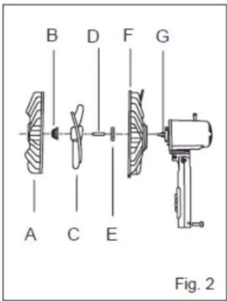
A. Front grille
B. Blade cap
C. Fan blade
D. Plasc sleeve
E. Plasc nut
F. Rear grille
G. Motor sha
H. Clutch knob
I. Motor housing
J. Push buon
K. Thumb screw
L. Power cord
M. Waterproof cover
N. Misng line holder
O. Internal pole
P. Height adjustment knob
Q. External pole
R. Misng line
S. Filter washer
T. Valve
U. Screws (pre-assembled)
V. Stand ornament
W. Base
ASSEMBLY INSTRUCTIONS
Before beginning assembly of product, make sure all parts are present. Compare parts with package contents list and diagram above. If any part is missing or damaged, do not aempt to assemble the product. Contact customer service for replacement parts.
Esmated Assembly Time: 15 minutes
Tools required for assembly: Phillips Screwdriver (not included)
FAN BASE ASSEMBLY - FIG. 1
- Unscrew the four screws (U) on the base (W), and then each the external pole (Q) to the base by hightening the four screws.
- Remove the height adjustment ring (P) by unscrewing it counterclockwise, and slide the stand ornament (V) down the external pole and over the base.
- Use your nger to pull out the internal pole (O). Slide the height adjustment ring over the internal pole. Fasten it to the external pole by turning the ring clockwise while holding the pole. Make sure the height adjustment ring is ghtly fastened before nal assembly.
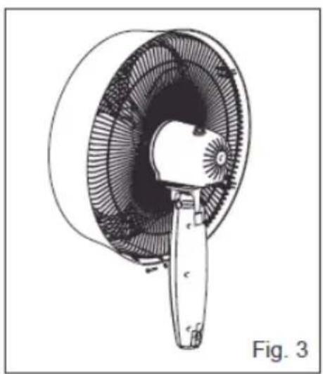
FAN HEAD ASSEMBLY – FIG. 2 & 3
- Remove the blade cap (B) by turning clockwise. Remove the plasc nut (E) by turning counterclockwise. Discard plasc sleeve (D).
- Posion the rear grille (F) over the motor sha (G). Make sure the handle is at the top and the one notch in the rear of the cover t over the three prongs on the motor housing (H).
- Secure the rear grille by turning the plasc nut (E) clockwise and ghtening rmly.
- Slide the fan blade (C), with the hollow interior of the blade facing towards the rear grille, onto the motor sha.
-
Secure the fan blade onto the motor sha by turning the blade cap counterclockwise unl it is rmly in place
-
Mount the front grille (A) with the logo in the proper direcon and secure the front grille and the rear grille together by fastening eight grille clips. Secure the screw.
FINAL ASSEMBLY - FIG. 4
- Loosen the thumb screw (K) by turning it counterclockwise.
- Always keep the water proof cover (M) even with the height adjustment knob (P) when adjusting the internal pole (O).
- Insert the internal pole into the neck joint and ghten by turning the thumb screw clockwise. Make sure it is ght enough to support the fan head.

natural_image
Technical line drawing of a fan or turbine component with internal blades and a handle, labeled Fig. 3 (no text or symbols on the diagram itself)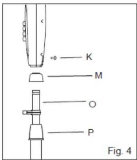
A Name You Can Count On
OPERATING INSTRUCTIONS
FAN-ONLY OPERATION
- Place the fan on a level surface. Plug the GFCI plug into a standard 120V 3-prong wall outlet.
- To start/stop fan oscillaon, push down/pull up the clutch knob (J).
- To adjust the airrow upward or downward, simply tilt the fan head by
hand and move to desired angle.
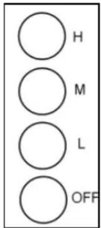
- Control speed by pushing the desired buon:
H-High (50W)
M - Medium (45W)
L - Low (40W)
OFF - Stop
- The height of the fan can be adjusted by loosening the height adjustment knob (P) and carefully raising or lowering the fan and reghtening the knob.
MISTING
- Connect a standard 3 14 garden hose to the misng hose valve (T). Water pressure should not exceed 555 153 kPa (5.62 kfg/cm2). The hose should be in good condion.
- With the garden hose turned on at the spigot, turn the lever on the misng hose valve to the right to turn on water to the fan.
- Turn the lever to the le to temporarily shut down the mist.
CLEANING & MAINTENANCE
The fan requires lile maintenance. Do not try to x it by yourself. Refer it to qualified service personnel if service is needed.
-
Disconnect from the electric socket during cleaning or assembly.
-
To ensure adequate air circulaon to the motor, keep the vents at the rear of the motor housing clear of dust, u, etc. Unplug the fan before using a vacuum cleaner to clean the grilles. It should not be necessary to disassemble the fan to clean it.
- Wipe the exterior with a so cloth soaked in a mild detergent. Do not use any abrasive detergents or solvents to avoid damaging the surface. Do not use gasoline, thinner, or bending to clean the fan.
- Do not allow water or any other liquid into the motor housing or interior parts.
MISTING NOZZEL MAINTENANCE
If the misng nozzles become clogged, unscrew them from the fan grille and soak in vinegar or a lime scale remover until they are clear of buildup. Use a non-metallic brush to scrub them if necessary. If the nozzles remain obstructed, contact the manufacturer for replacements.
Warning: never try to clear the nozzles with pins or other sharp objects as this can cause damage.
If the misng hose valve becomes clogged, unscrew the head of the valve and ush it with running water to clear debris. Make sure the screen inside the misng hose is clean as well.
STORAGE
Before storing, follow the assembly instrucons in reverse to dismantle the fan. Clean the individual parts with a so, damp cloth and allow the pieces to dry completely before packing. Pack it in the original box, or cover it with plasc or cloth. Store the fan in a clean, dry place.
TROUBLESHOOTING
| Problem | Possible Causes | Soluon |
| The fan has no power. | The unit may be plugged in using a dierent voltage. | Check if using the wrong voltage. |
| The circuit breaker may be tripped or there is a blown fuse. | Reset the circuit breaker or check for a broken fuse. | |
| The fan is not rotang. | There is an obstrucon. | Check for obstrucons in the fan. If you nd something, turn the fan o. Unplug the fan and carefully remove the obstrucon. Plug the fan in and turn it on again by referring to the operang instrucons. |
| No mist is produced. | There is no water coming from the hose. | Make sure the garden hose is correctly connected to the spigot and the misng hose valve, that the spigot is turned on, and that the valve is open. |
| Nozzles are leaking or dripping. | The nozzles are clogged. | Clean the clogged nozzles on the front of the fan as described under “Cleaning & Maintenance.” |
LIMITED MANUFACTURER'S WARRANTY
This appliance is covered by a limited manufacturer's warranty. For one year from the original date of purchase, the manufacturer will repair or replace any parts of this appliance that prove to be defective in materials and workmanship, provided the appliance has been used under normal operang conditions as intended by the manufacturer.
Warranty Terms:
During the rst year, any components of this appliance found to be defective due to materials or workmanship will be repaired or replaced, at the manufacturer's discreet, at no charge to the original purchaser. The purchaser will be responsible for any removal or transportaon costs.
Warranty Exclusions:
The warranty will not apply if damage is caused by any of the following:
- Power failure
- Damage in transit or when moving the appliance
- Improper power supply such as low voltage, defective household wiring or inadequate fuses
- Accident, alteraon, misuse or abuse of the appliance such as using non-approved accessories, inadequate air circulaon in the room or abnormal operang condions (extreme temperatures)
- Use in commercial or industrial applicaons
- Fire, water damage, the, war, riot, hostility or acts of God such as hurricanes, oods, etc.
- Use of force or damage caused by external inuences
- Parally or completely dismantled appliances
- Excess wear and tear by the user
Obtaining Service:
When making a warranty claim, please have the original bill of purchase with purchase date available. Once conrmed that your appliance is eligible for warranty service, all repairs will be performed by a NewAir™ authorized repair facility. The purchaser will be responsible for any removal or transportaon costs. Replacement parts and/or units will be new, re-manufactured or refurbished and is subject to the manufacturer's discreet. For technical support and warranty service, please email support@newairusa.com.

- 16" Outdoor Misting Fan
- OWNERS MANUAL
- A Name You Can Trust
- Count on NewAir.
- READ AND SAVE THESE INSTRUCTIONS.
- TABLE OF CONTENTS
- SPECIFICATIONS
- SAFETY INFORMATION & WARNINGS
- PARTS LIST
- ASSEMBLY INSTRUCTIONS
- FAN BASE ASSEMBLY - FIG. 1
- FAN HEAD ASSEMBLY – FIG. 2 & 3
- FINAL ASSEMBLY - FIG. 4
- OPERATING INSTRUCTIONS
- FAN-ONLY OPERATION
- MISTING
- CLEANING & MAINTENANCE
- MISTING NOZZEL MAINTENANCE
- STORAGE
- TROUBLESHOOTING
- LIMITED MANUFACTURER'S WARRANTY
- Warranty Terms:
- Warranty Exclusions:
- Obtaining Service:
Brand : NewAir
Model : AF-520B
Category : Household Fan