
SLT973 - Range hood SIRIUS - Free user manual and instructions
Find the device manual for free SLT973 SIRIUS in PDF.


| Product Type | Range Hood |
| Brand | Sirius |
| Model | SLT973 |
| Installation Type | Built-in (plasterboard ceiling niche) |
| Ceiling Opening Diameter | 510 mm |
| Minimum Distance from Floor | 2000 - 2100 mm |
| Distance Between Plasterboard and Solid Ceiling (Hood Version) | 220 - 300 mm |
| Distance Between Plasterboard and Solid Ceiling (Lamp Version) | 100 mm |
| Air Outlet Diameter | 150 mm |
| Maximum Duct Length | 5 m |
| Minimum Distance Above Gas Hob | 650 mm |
| Power Supply | 220-240 V, 50/60 Hz (from rating plate) |
| Power Cord | Yes, with plug (accessible) |
| Motor | Internal, multiple speeds |
| Suction Speeds | 4 (1st to 4th, with auto reduction) |
| Filter Type | Grease filter (metal mesh); optional carbon filter |
| Control Type | Remote control (radio frequency 433.92 MHz) |
| Remote Battery | 12 V, type 27A alkaline |
| Lighting | LED, dimmable (20% to 100%) |
| Timer | 10-minute countdown; auto switch-off after 4 hours |
| Speed Auto Reduction | Yes (from 4th to 3rd after 5 min, from 3rd to 2nd after 7 min for external motors) |
| Stand-by Power Consumption | < 0.5 W |
| Safety Features | Ground connection required; emergency button; anti-flooding design |
| Compliance | CE, WEEE (2012/19/EC), R&TTE Directive 99/5/EC |
| Weight (approx.) | 15 kg |
Frequently Asked Questions - SLT973 SIRIUS
User questions about SLT973 SIRIUS
0 question about this device. Answer the ones you know or ask your own.
Ask a new question about this device
Download the instructions for your Range hood in PDF format for free! Find your manual SLT973 - SIRIUS and take your electronic device back in hand. On this page are published all the documents necessary for the use of your device. SLT973 by SIRIUS.
USER MANUAL SLT973 SIRIUS
IT ISTRUZIONI PER INSTALLAZIONE USO E MANUTENZIONE
GB INSTALLATION, USE AND MAINTENANCE INSTRUCTION
SLT973 - SLT973 LAMP
The symbol on the product or on its packaging indicates that this product may not be treated as household waste. Instead it shall be handed over to the applicable collection point for the recycling of electrical and electronic equipment. By ensuring this product is disposed of correctly, you will help prevent potential negative consequences for the environment and human health, which could otherwise be caused by inappropriate waste handling of this product. For more detailed information about recycling of this product, please contact your local city office, your household waste disposal service or the shop where you purchased the product. This appliance is marked according to the European directive 2012/19/EC on waste electrical and electronic equipment (WEEE).
 7 7 |  8 8 |
 9 9 | 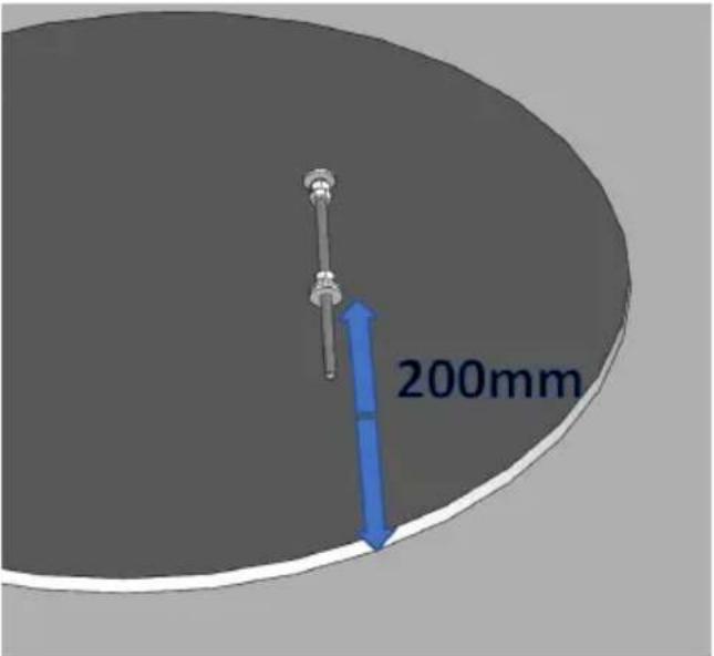 10 10 |
  11 11 | 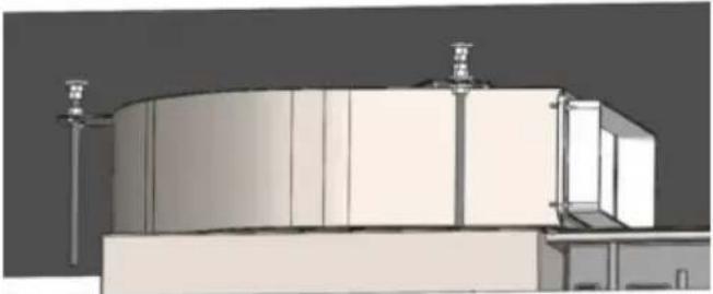 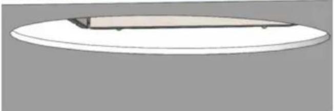 12 12 |
INDICE

Avvertenze
Sistema d'uso
natural_image
Black remote control device with a circular button and four buttons (no visible text or symbols)Installation of the hood version
Installation lamp version
Functioning
Maintenance
WARNINGS
In order to install the product, two people are required.
Children and inexperienced or disabled people may use the appliance only under the supervision of adults.
The air sucked can't be conveyed through or into a duct used to let out fumes from appliances fed by energy.(eg. centralized heating, radiators, waterheaters, etc.).
To evacuate the air outlet, please comply with the pertaining rules given by competent authorities.
Provide for an adequate room ventilation when hoods and appliances powered by energy (gas, oil, coal stoves, etc.), are used in the following ways at the same time.
The hood may create a nega- tive pressure in the room eva- cuating the air.
The negative pressure in the room must not exceed 0.04 mbar, avoiding the suction of exhaust gases from the heat source.
Therefore, the room must be equipped with air intakes that supply a constant flow of fresh air.
In case of installation with gas cooker hob, the minimum distance between the lower part of the hood and the stove must be at least 650 mm.
During the electrical connection, make sure that the power socket is equipped with a ground connection and check that the voltage values correspond to those indicated on the plate inside the appliance.
Before any cleaning or maintenance work, the appliance must be disconnected from the power grid.
If the appliance is not equipped with a non flexible cable or plug, or other device to ensure Omni polar disconnection from the grid, with an opening distance of at least 3 mm, then these gird disconnectors must be provided in the fixed installation.
If the appliance is equipped with a power cable and a plug, it must be placed so that the plug is accessible.
Avoid the use materials that cause flames in the immediate proximity of the appliance. In the case of fried food, please pay particular attention to fire hazard that constitute oil and grease. The oil already used is particularly dangerous for its flammability. Do not use uncovered electric grids.
To avoid a possible fire risk, follow the instructions given for cleaning the grease filters and removing any grease deposits on the unit.
USAGE SYSTEM
PANEL OPENING
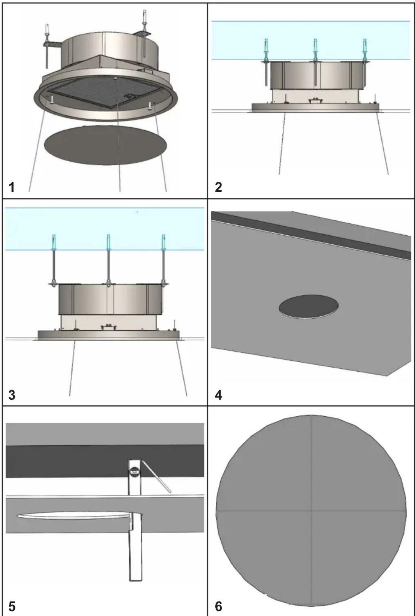
It is possible to open the grease filter cover panel pulling it gently, as shown in fig. 1.
The panel is fixed with three magnets, there are two safety cables to release in order to remove the panel from the product.
For the proper functioning, it is recommended to install the product at a maximum distance of 2000 - 2100 mm, from the floor level.
Before proceeding with the installation of the appliance, check that all the components are not damaged otherwise, please contact the dealer and do not continue with the installation.
Use an air outlet pipe with a maximum length of no more than 5 metres.
- Reduce the number of curves in the duct as each curve reduces the suction efficiency equivalent to 1 linear meter. (E.g.: if 2 90° curves are used, the length of the duct should not exceed 3 meters in length).
- Avoid drastic changes of direction.
- Use a duct with a diameter of 150mm constant over the entire length.
- Use a duct of recognized and approved material.
HOOD VERSION INSTALLATION
For the installation of this product it is necessary to create a plasterboard lowering, keeping at least 220mm distance between the same and the solid ceiling.
The material supplied with the product allows it to be installed on lowerings ranging from 220mm (fig. 2) to 300mm (fig. 3) of distance between the plasterboard and the solid ceiling.
It is necessary to make a circular opening in the plasterboard, with a diameter equal to: 510mm (fig. 4)
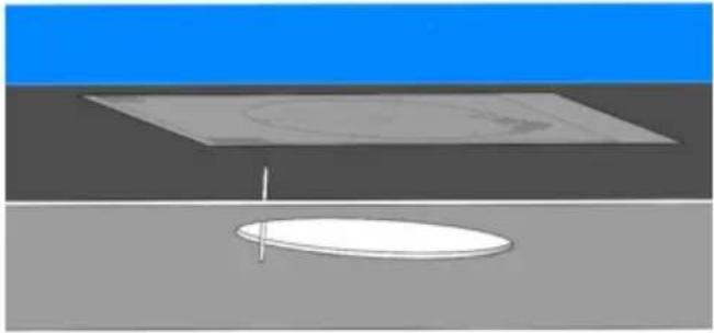
Using a level and a pencil, bring the four ends of the holes created in the plasterboard directly into the solid ceiling, see fig. 5, then draw perpendicular lines as shown in fig. 6, in order to find the center of the hole.
Position the drilling template supplied, aligning the centre of the template with the centre of the axes previously drawn (fig. 7). Using a pencil, trace the three holes to be made in the solid ceiling.
Before tracing the holes you can rotate the drilling template in order to orient the air outlet of the fan in the desired direction. The position of the air outlet of the fan is indicated in the drilling template.
Perform the three holes in the solid ceiling using a helical tip with a diameter of 8mm.
Insert the metric inserts supplied into the holes made.
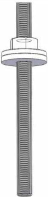
Insert the threaded bars into the metric inserts previously installed.
Screw the threaded bars using two nuts, as shown in fig. 8, act in the nut below to screw the threaded bar.
Insert an additional nut, a metal washer and a plastic locking washer as shown in figure 9. For correct installation, position the metal washer 200mm high from the bottom surface of the plasterboard, see figure 10.
Remove the product from its packaging and place it on a suitable surface: we suggest using a soft material, such as a sponge or a cloth.
Open the panel as shown in Fig. 1 and described in the previous paragraph, remove the grease filter using the handle.
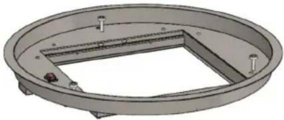
Using a suitable tool, remove the eight screws securing the outer frame and then remove it as shown in Fig. 11.
Also disconnect the flat cable and the electrical cable of the reset button.
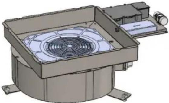
Install the upper part of the product in the plaster-board niche, the three slots must coincide with the threaded rods previously installed, as shown in fig. 12.
Bring the product to a stop with the washers previously positioned.
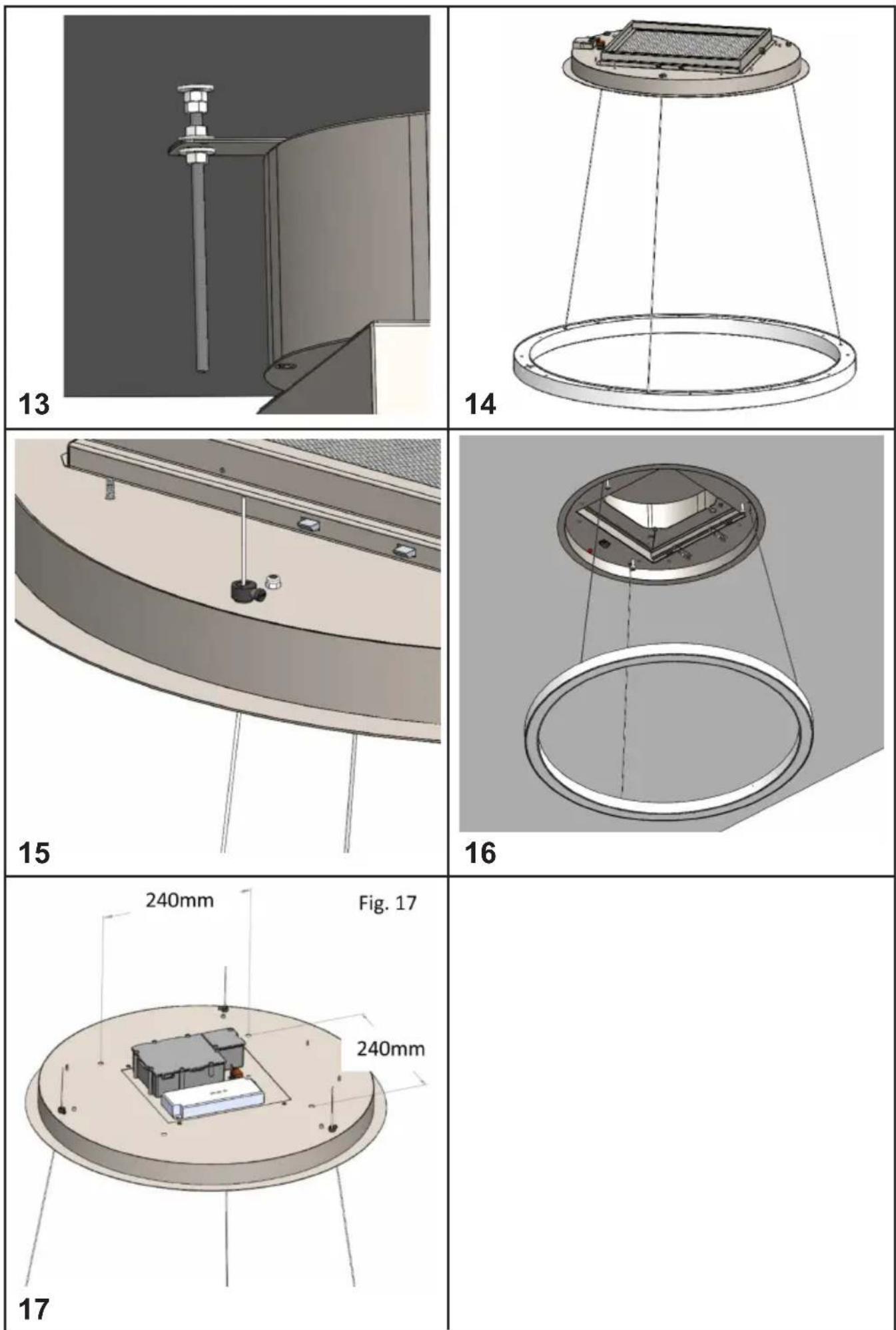
Secure the product with three washers and three nuts supplied. (fig. 13)
Connect the air outlet duct and the power supply.
Remove the LED ceiling light from its packaging and run the cables through the three holes in the frame (fig. 14).
Adjust the desired height of the LED ceiling light to the floor using the cable clamp as shown in fig. 15. Move the frame closer to the plasterboard niche, then restore the previously removed electrical connections and make the electrical connection of the LED ceiling light, taking care not to confuse the positive, negative and ground polarities indicated by the labels in the electrical cables.
Lock the niche to the product previously fixed with the eight screws previously removed, fig. 16.
Restore the grease filter and the metal panel fixed with special magnets.
LAMP VERSION INSTALLATION
For the installation of the product in lamp version it is necessary to create a plasterboard lowering, keeping at least 100mm distance between the same and the solid ceiling.
A circular opening must be made in the plasterboard, with dimensions equal to: 510mm (fig. 4)
Make a metal or wooden structure on which to fix the product; consider the fixing holes indicated in fig. 17.
In addition to what is indicated above, proceed with the installation as for the hood product, indicated in the previous chapter.
WORKING
RC001
RADIO CONTROL
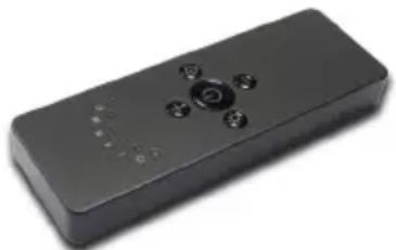
Radio control used for the remote operation of ducted cooker hoods.
TECHNICAL DATA
- Alkaline battery powered: 12 V mod. 27A
- Operating frequency: 433.92 Mhz
- Combinations: 32.768
- Max. consumption: 25 mA
- Operating temperature: -20 ÷ + 55 °C
- Dimensions: 130x45x15 mm.
OPERATING DESCRIPTION
The transmitter is equipped with 5 buttons for co-oker hood management, as specified below:
Light ON/OFF command.
Motor ON (speed level 1) / OFF command.
Reduce speed.
+ Increase speed.
10-minute timer.
DIMMABLE LIGHTS FUNCTION
THIS FUNCTION PROVIDES FOR LIGHTS DIMMABILITY, RANGING FROM 20% TO 100%, BY CONTINUOUSLY PRESSING THE LIGHT KEY ON THE REMOTE CONTROL.
FUNCTIONS ARE THE FOLLOWING:
- HOOD LIGHT OFF - SHORTLY PRESS THE KEY - LIGHT ON AT 100%.
- LIGHT ON AT 100% - SHORTLY PRESS THE KEY - LIGHT OFF.
- LIGHT ON AT 100% - CONTINUously PRESS THE KEY - BRIGHTNESS REDUCTION.
- RELEASING THE KEY DURING REDUCTION OR INCREASE - LIGHT KEEPS THE LUMINOUS INTENSITY REACHED.
- LIGHT ON - DIMMED - CONTINUously PRESS THE KEY - BRIGHTNESS IS INVERTED IF COMPARED TO THE PREVIOUS FUNCTION.
The manufacturer supplies the radio control unit ready to be used with codes preset in the Factory
natural_image
Black remote control device with indicator lights and buttons (no visible text or symbols)OPERATION MODE
Standard configuration:
Standard configuration requires all “cooker hoods – radio control - system” to be provided with the same transmission code. In the event two cooker hoods – radio control system are installed in the same room or nearby, each system may affect the operation of the another. Therefore, the code of one radio control system must be changed.
Generating a new transmission code:
The radio control system is provided with preset codes. Should new codes be required, proceed as follows: Press simultaneously buttons:
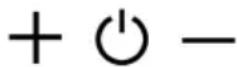
for two seconds. When Leds light on, press buttons:
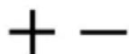
(within 5 seconds). Leds flashing 3 times indicate the procedure is completed.
WARNING! This operation deletes permanently the preset codes.
Learning the new transmission code:
Once the transmission code is changed in the radio control unit, the electronic central unit of the cooker hood must be made to set the new code in the following way:
Press the main power-off button of the hood and then restore power to the electronic control unit.
Within the next 15 seconds, press the Liight Button ⚙ to synchronise the central unit with the code.
Reset of the Factory configuration:
To restore the Factory configuration, follow the procedure described below: press simultaneously buttons:

for 2 seconds. When Leds light on, press buttons:


(within 5 seconds). Leds flashing 6 times indicate the procedure is completed.
WARNING! This operation deletes permanently the preset codes.
Emergency button:
In the event that the radio control does not work, use the emergency button to switch the appliance off. After any necessary repairs have been performed, reset the emergency button.
WARNING
The battery should be replaced every year to guarantee the optimal range of the transmitter. To replace the exhausted battery, take the plastic lid off, remove the battery and replace it with a new one, observing the correct battery polarities.
Used batteries should be discarded in special collection bins.
The below product:
RC001 Radiio Controll
complies with the specifications set out in the R&TTE Directive 99/5/EC.

WARNING
Any adjustments or modifications which have not been expressly approved by the holder of the legal conformity certificate may invalidate the user's rights relating to the operation of the device.
Rev. 0 26/08/14
The products are endowed with an electronic device which allows the automatic switching off after 4 hours working from the last operation.
TIMING
As a result of the new EU65 “Energy label” and EU66 “Ecodesign” regulations issued by the European Commission, which came into force as from January 1st, 2015, our products have been adapted to comply with these new requirements. All of the models complying with the energy label requirements, are equipped with new electronics including a timer device for suction speeds control, when the air capacity exceeds 650m^3/h .
Internal motor models, with maximum air capacity higher than 650m^3/h , are equipped with a timer device that automatically switches the suction speed from 4th to 3rd speed, after 5 minutes operation.
External motor models are equipped with remote motors that, as for internal motor versions, include a timer device that switches down the suction speed when it exceeds 650 m³/h. (See External Motors Instructions).
Remote motors, whose air capacity exceeds 650m^3/h at both 4th and 3rd speed, will have the following by default timer control functions: The suction speed is automatically switched from 4th to 2nd speed, after 6 minutes operation.
If the appliance is working at 3rd speed, it is automatically switched to 2nd speed, after 7 minutes operation. Operation speeds can also be changed during operation.
The energy consumption of the appliance in stand – by mode is lower than 0.5W.
MAINTENANCE
Careful maintenance ensures smooth operation and long-lasting performance.
Special care must be taken with the grease filter: To access the filter, proceed as follows: In the Chapter → OPENING THE PANEL.
Remove the grease filter using the special handle.
To replace the grease filter after cleaning, fulfil the same operation in reverse order.
To remove the carbon filter, if installed, follow the same steps as the grease filter.
The carbon filter is located immediately above the grease filter.
Warm water and neutral detergents are recommended to clean up the appliance, while abrasive products should be avoided.
If the power cord is damaged, a qualified person must replace it.
It is possible to open the grease filter cover panel pulling it as shown in fig. 1.
The panel is fixed with three magnets, there are two safety cables to be released to remove the panel from the product.
For proper operation, it is recommended to install the product at a maximum distance, from the floor level, of 2000 - 2100 mm.
- INDICE
- Avvertenze
- WARNINGS
- USAGE SYSTEM
- PANEL OPENING
- HOOD VERSION INSTALLATION
- LAMP VERSION INSTALLATION
- WORKING
- RC001
- RADIO CONTROL
- TECHNICAL DATA
- OPERATING DESCRIPTION
- DIMMABLE LIGHTS FUNCTION
- OPERATION MODE
- Generating a new transmission code:
- WARNING! This operation deletes permanently the preset codes.
- Learning the new transmission code:
- Reset of the Factory configuration:
- Emergency button:
- WARNING
- TIMING
- MAINTENANCE
Brand : SIRIUS
Model : SLT973
Category : Range hood