
01740 - Motion detector Vimar - Free user manual and instructions
Find the device manual for free 01740 Vimar in PDF.


| Product Type | Motion Detector |
| Brand | Vimar |
| Model | 01740 |
| Detection Technology | Passive Infrared (PIR) |
| Detection Angle | 180° |
| Detection Range | 12 m |
| Power Supply | 230 V AC, 50 Hz |
| Maximum Load | 1000 W incandescent / 300 W LED |
| Operating Temperature | -10°C to +40°C |
| IP Rating | IP44 |
| Installation | Wall or ceiling mount |
| Dimensions (H x W x D) | 100 mm x 80 mm x 60 mm |
| Weight | 150 g |
| Adjustable Time Delay | 10 seconds to 10 minutes |
| Adjustable Light Sensitivity | 3 to 2000 lux |
| Certification | CE |
| Maintenance | Clean lens with soft dry cloth |
| Safety | Disconnect power before installation |
| Spare Parts | Not available; replace entire unit |
| Repairability | Non-repairable; replace if faulty |
Frequently Asked Questions - 01740 Vimar
User questions about 01740 Vimar
0 question about this device. Answer the ones you know or ask your own.
Ask a new question about this device
Download the instructions for your Motion detector in PDF format for free! Find your manual 01740 - Vimar and take your electronic device back in hand. On this page are published all the documents necessary for the use of your device. 01740 by Vimar.
USER MANUAL 01740 Vimar
natural_image
White rectangular metal enclosure with two recessed windows and a small mounting base (no text or symbols visible)01740
Rivelatore IR a tenda PET immune IR motion tent detector PET immune

natural_image
Blank gray image with no visible content, text, or symbolsITALIANO
natural_image
Line drawing of hands using a screwdriver to adjust or install a wall-mounted device (no text or symbols visible)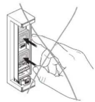
natural_image
Hand inserting a cable into a device panel (no text or symbols visible)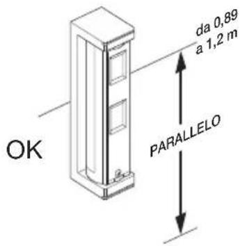
natural_image
Illustration of a person walking toward a target with directional arrows indicating motion (no text or symbols)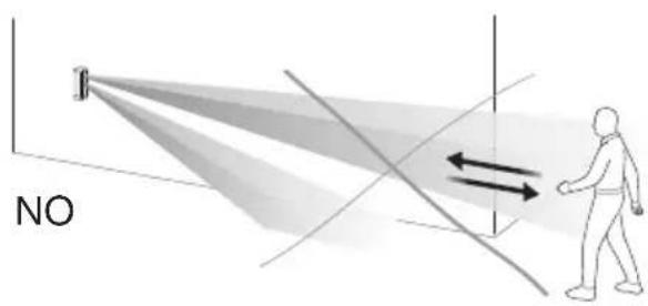
Installazione
natural_image
Diagram showing two identical mechanical or optical setups with light beams projecting onto a central component, no text or symbols present.natural_image
Diagram of a mechanical assembly with a spring and housing component (no text or symbols)natural_image
Illustration of a person walking under a spotlight beam with directional arrows indicating light or motion (no text or symbols)natural_image
Blank gray image with no visible content, text, or symbolsENGLISH
- FEATURES 14
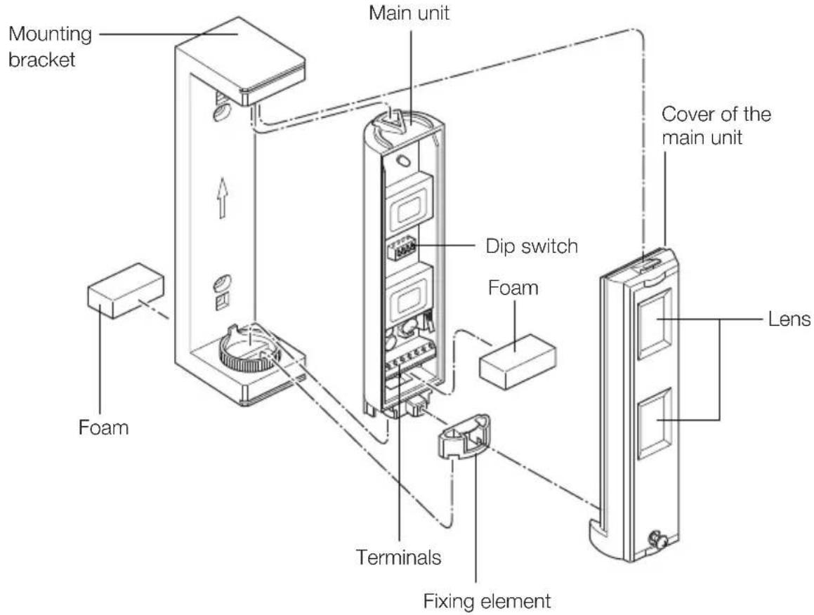
- THE DETECTOR AND ITS PARTS .... 14
- CONNECTIONS 15
3.1 Connection to the control unit 15
3.2 Line-end resistor connection 17
- DETECTOR CONFIGURATION....17
4.1 LED configuration (Dip switch 1) 18
4.2 Alarm Output configuration (Dip switch 2) 18
4.3 PIR Sensitivity configuration (Dip switch 3).... 18
4.4 Anti-masking configuration (Dip switch 4) 18
- LED SIGNALLING 19
- COVER DIAGRAMS 19
- INSTALLATION 20
7.1Warnings....20
7.2 Installation procedure 20
- WALK TEST ...... 23
- INSTALLATION RULES ...... 23
- REGULATORY COMPLIANCE 23
Characteristics - The detector and its parts
By-alarm curtain-effect detector to protect entrances and openings such as doors, windows, covered terraces, corridors and French doors, short-range curtain-effect detection with adjustable lens up to 2 m or 5 m, PET immune, anti-masking function, 1 NO or NC 28 VDC 0.1A relay output, surface mounting, 9.5-18 VDC 20 mA power supply.
1. CHARACTERISTICS
• Power supply: 12 VDC
- Absorption: 20 mA
- Cover: 5x1 m
• Detection length limit: 5 m
- Alarm output: N.C./N.O. 28 VDC 0.1 A (max) selectable
- Fault output: N.C. 28 VDC 0.1 A (max)
- Tamper output: N.C. 28 VDC 0.1 A (max), open when the cover is removed
• Detectable speed: from 0.3 to 1.5 m/s
- Sensitivity: 2.0^ C (at 0.6 ~m / s )
• Alarm duration: 2 ± 1 s
- Front LED:
- permanently lit -> alarm
- flashing -> heating and masking detection
• Heating time: approx. 60 s
- Operating temperature: - 20..+ 60 °C
- Ambient humidity: 95%
• Protection degree: IP55
2. THE DETECTOR AND ITS PARTS
3. CONNECTIONS
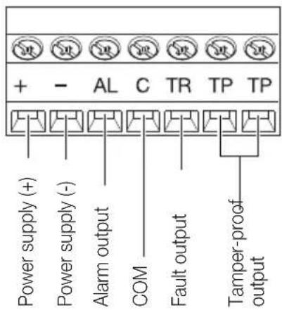
Caution:
- The anti-masking output is recognised as a Fault output.
- For generic balancing resistors, see para. 3.2.
Power supply cables.
| Diameter | Max. length | |
| 12 V 14 V | ||
| AWG22 (0.33 mm ^2 ) | 290 m 620 m | |
| AWG20 (0.52 mm ^2 ) 450 m 980 m | ||
| AWG18 (0.83 mm ^2 ) 720 m 1570 m | ||
3.1 Connection to the control unit
Single balancing
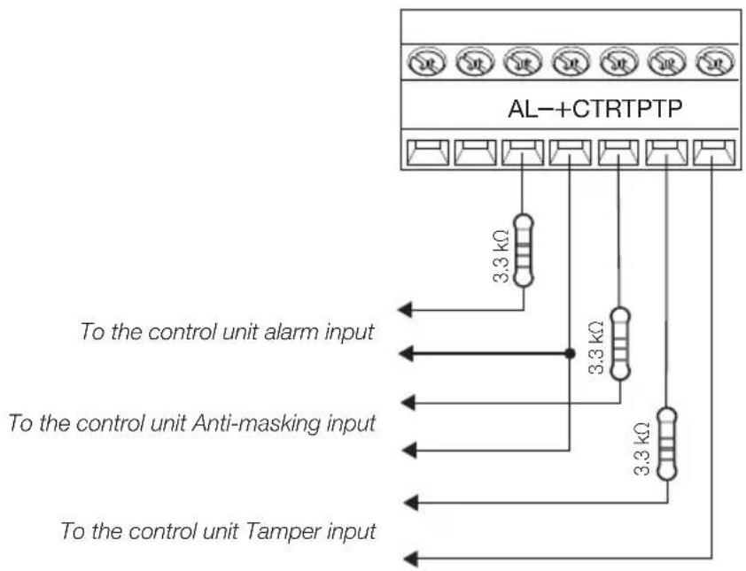
flowchart
graph TD
    A["AL-+CTRTPTP"] -->|3.3 kΩ| B["To the control unit alarm input"]
    A -->|3.3 kΩ| C["To the control unit Anti-masking input"]
    A -->|3.3 kΩ| D["To the control unit Tamper input"]
Connections
Double balancing
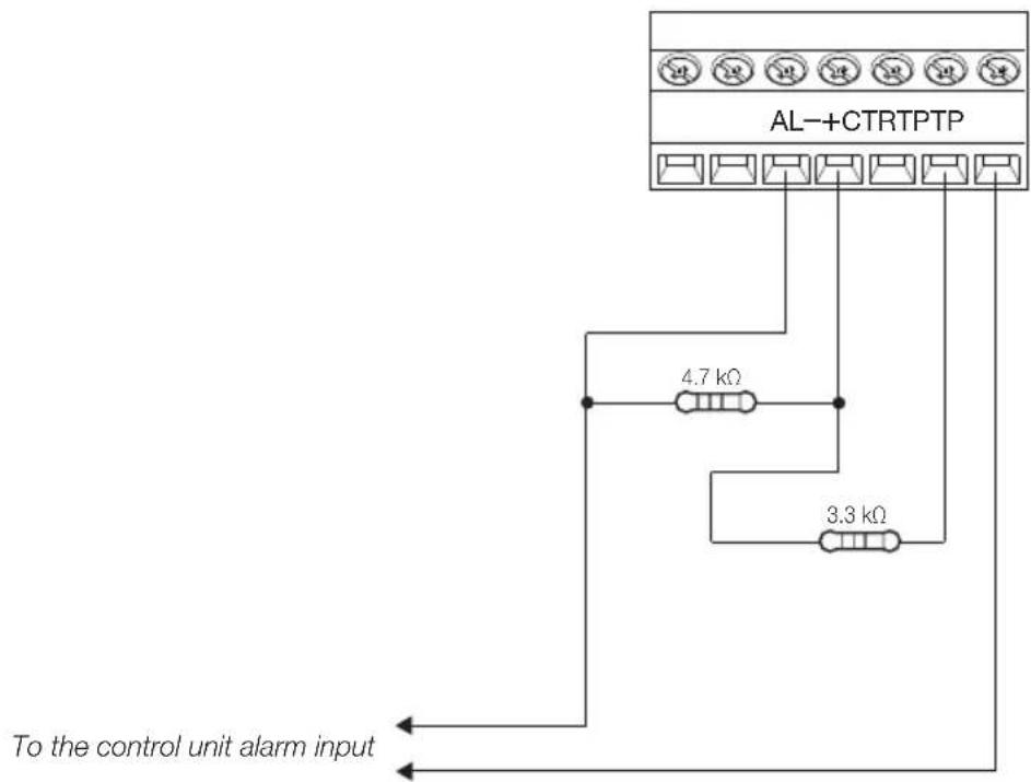
Triple balancing
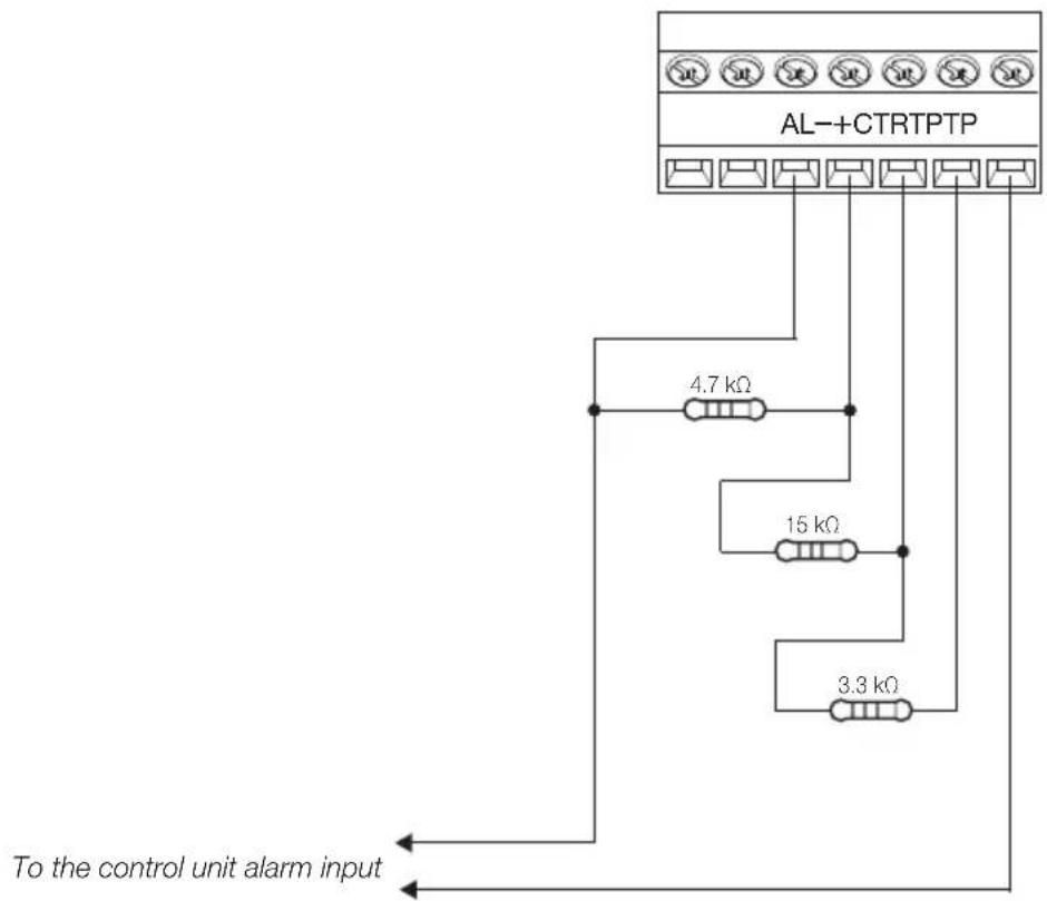
Connections - Detector configuration
3.2 Balancing resistor connection.
Since the alarm and fault outputs share the COM terminal, make the connections as indicated below.
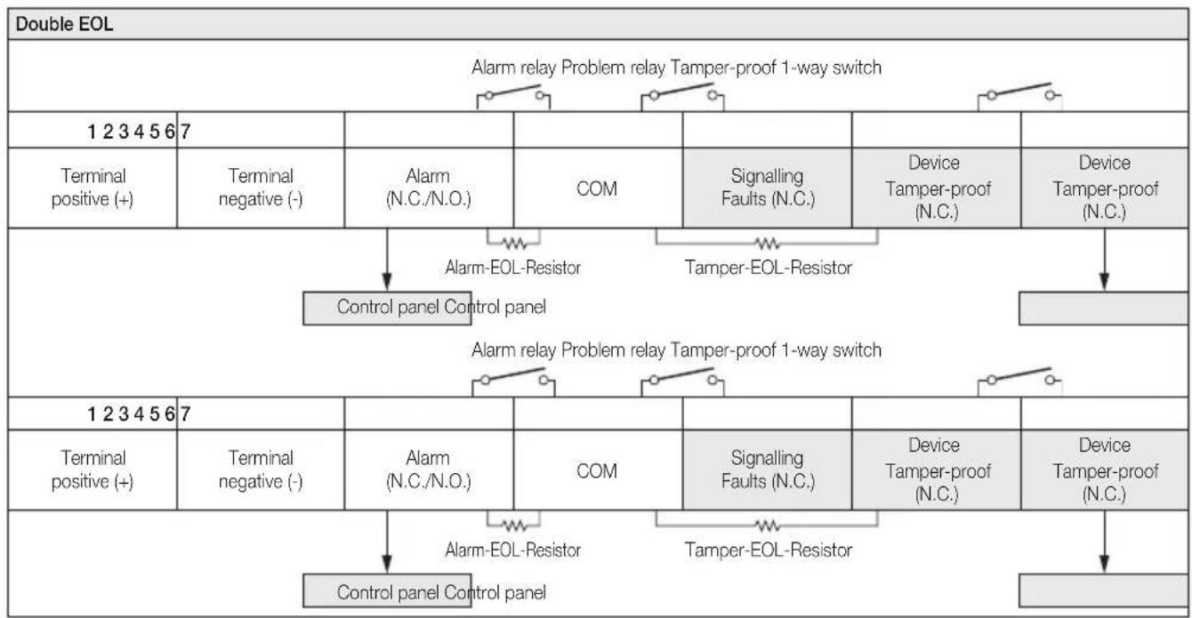
flowchart
graph TD
    A["Double EOL"] --> B["Alarm relay Problem relay Tamper-proof 1-way switch"]
    B --> C["1 2 3 4 5 6 7"]
    C --> D["Terminal positive (+)"]
    C --> E["Terminal negative (-)"]
    D --> F["Alarm (N.C./N.O.)"]
    E --> G["COM"]
    F --> H["Alarm-EOL-Resistor"]
    G --> I["Signalling Faults (N.C.)"]
    H --> J["Tamper-EOL-Resistor"]
    I --> K["Device Tamper-proof (N.C.)"]
    J --> L["Device Tamper-proof (N.C.)"]
    M["1 2 3 4 5 6 7"] --> N["Terminal positive (+)"]
    M --> O["Terminal negative (-)"]
    N --> P["Alarm (N.C./N.O.)"]
    O --> Q["COM"]
    P --> R["Alarm-EOL-Resistor"]
    Q --> S["Signalling Faults (N.C.)"]
    R --> T["Tamper-EOL-Resistor"]
    S --> U["Device Tamper-proof (N.C.)"]
    T --> V["Device Tamper-proof (N.C.)"]
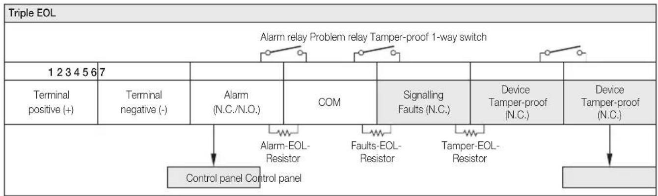
flowchart
graph TD
    A["Triple EOL"] --> B["Alarm relay Problem relay Tamper-proof 1-way switch"]
    B --> C["1 2 3 4 5 6 7"]
    C --> D["Terminal positive (+)"]
    C --> E["Terminal negative (-)"]
    B --> F["COM"]
    B --> G["Signalling Faults (N.C.)"]
    B --> H["Device Tamper-proof (N.C.)"]
    B --> I["Device Tamper-proof (N.C.)"]
    J["Control panel Control panel"] --> K["Alarm-EOL-Resistor"]
    J --> L["Faults-EOL-Resistor"]
    J --> M["Tamper-EOL-Resistor"]
4. DETECTOR CONFIGURATION
Configuration is done using the dip switches found on the device electronic board.
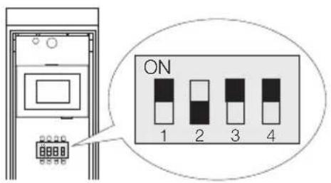
1 LED
2 ALARM OUTPUT
3 PIR SENSITIVITY
4 ANTI-MASKING
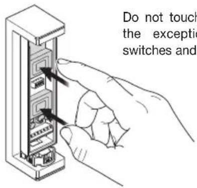
Do not touch the board with the exception of the dip switches and the terminal.
Detector configuration
4.1 LED configuration (Dip switch 1)
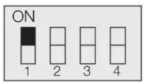

| Position Functions | |
| ON(default setting) | LED ON |
| OFF LED OFF |
4.2 Alarm Output configuration (Dip switch 2)
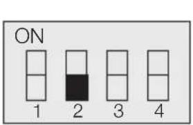

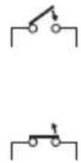
| Position Functions | |
| N.O.(default setting) | OUTPUT N.O. |
| N.C. OUTPUT N.C. |
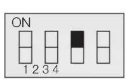
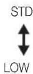
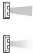
4.3 PIR Sensitivity configuration (Dip switch 3)
| Position Functions | |
| STD(default setting) | NORMAL SENSITIVITY |
| LOW LOW SENSITIVITY | |
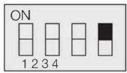
4.4 Anti-masking configuration (Dip switch 4)
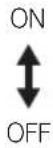
| Position Functions | |
| ON (default setting) | ANTI-MASKING ACTIVATED |
| OFF | ANTI-MASKING DEACTIVATED |
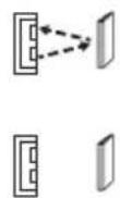
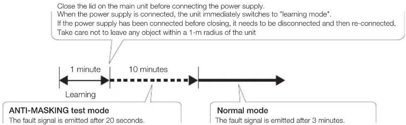
If the masking condition persists for more than 3 minutes, a FAULT signal is generated. The fault signal is generated after 20 seconds, in anti-masking test mode.
flowchart
graph LR
    A["1 minute"] --> B["10 minutes"]
    B --> C["Normal mode"]
    style A fill:#f9f,stroke:#333
    style B fill:#ccf,stroke:#333
    style C fill:#cfc,stroke:#333
If a fault output is signalled (incorrect masking detection) immediately after power-on, set DIP switch 4 (ANTI-MASKING) to "OFF", then to "ON" and then close the cover.
5. LED SIGNALLING
The LED signals the alarm condition, the masking attempt and the device heating phase.
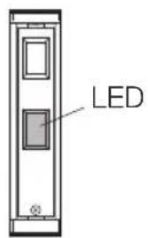

| Detector statuses LED indications | |
| Heating• The LED flashes even if DIP SWITCH 1 is set to “OFF” Flashes for approximately 60 seconds | 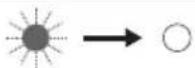 |
| Alarm |  Lights up for 2 seconds. Lights up for 2 seconds. |
| Masking detection• The LED flashes even if DIP SWITCH 1 is set to “OFF” |  Flashes 3 times and then repeats the sequence Flashes 3 times and then repeats the sequence |
6. COVER DIAGRAMS
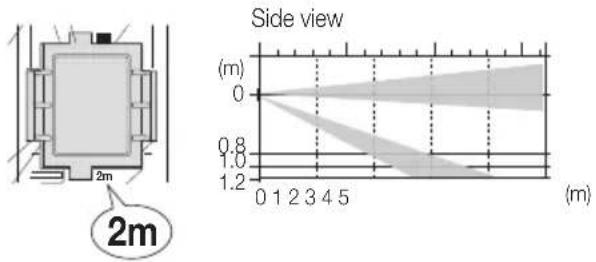
Top view Side view
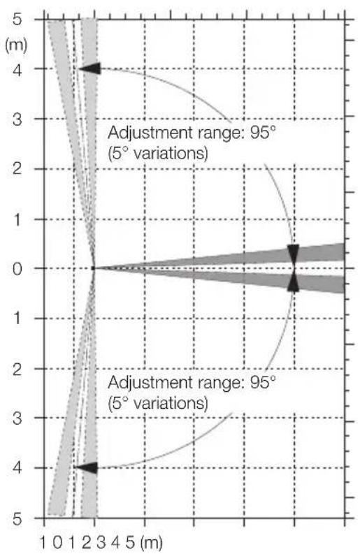
line
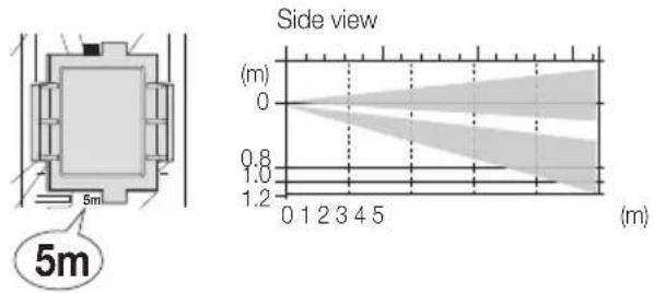
| Position (m) | Value | | ------------ | ----- | | 0 | 0 | | 1 | 1 | | 2 | 2 | | 3 | 3 | | 4 | 4 | | 5 | 5 |Detection range 5m
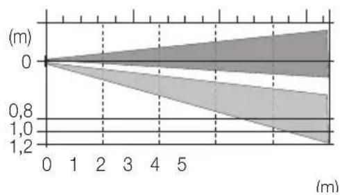
area
| Time (m) | Value | | -------- | ----- | | 0 | 0 | | 1 | 0.8 | | 2 | 1.0 | | 3 | 1.2 | | 4 | 1.0 | | 5 | 0.8 |Detection range 2m
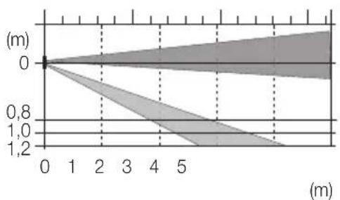
area
| x | y | |----|------| | 0 | 0.0 | | 1 | 0.8 | | 2 | 1.0 | | 3 | 1.2 | | 4 | 1.0 | | 5 | 0.8 |7. INSTALLATION
7.1 Warnings
Do not remove the board.
Do not touch the board, with the exception of the DIP switch.
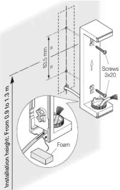
Mounting height.
natural_image
Illustration of hands using a screwdriver to adjust or install an electrical panel (no text or symbols visible)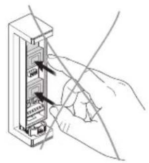
natural_image
Hand inserting a cable into a server rack (no text or symbols visible)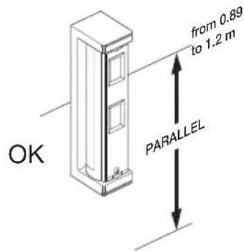
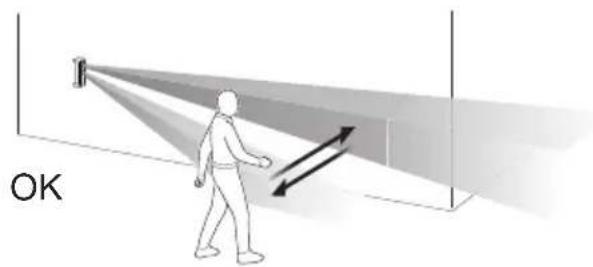
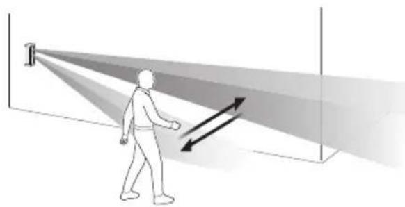
Direction of detection of an approaching person:
natural_image
Illustration of a person walking toward a beam with directional arrows, no text or symbols present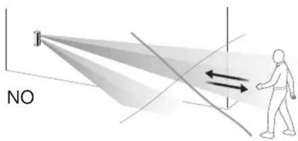
7.2 Installation procedure
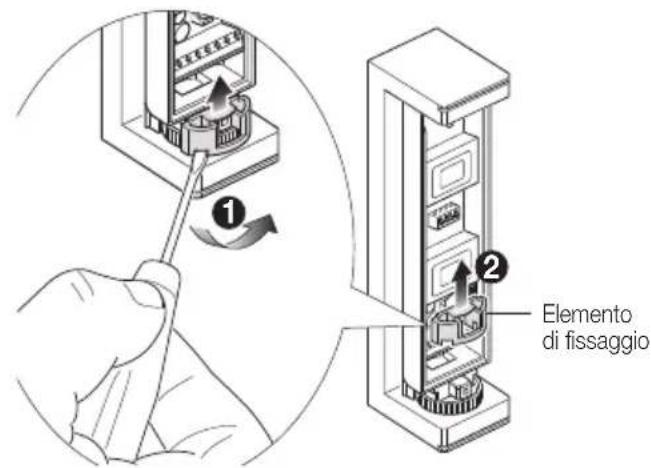
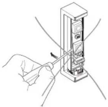
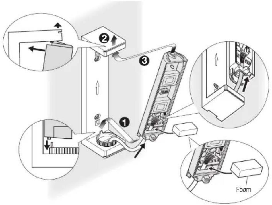
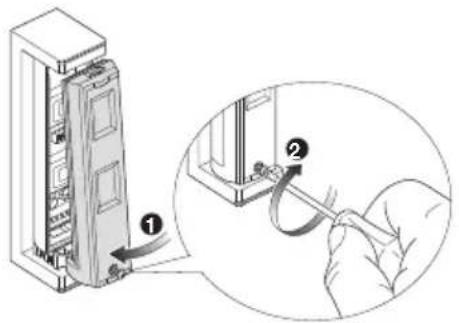
- Open the cover on the main unit. 2. Remove the fixing element.
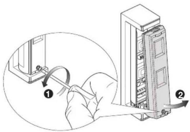
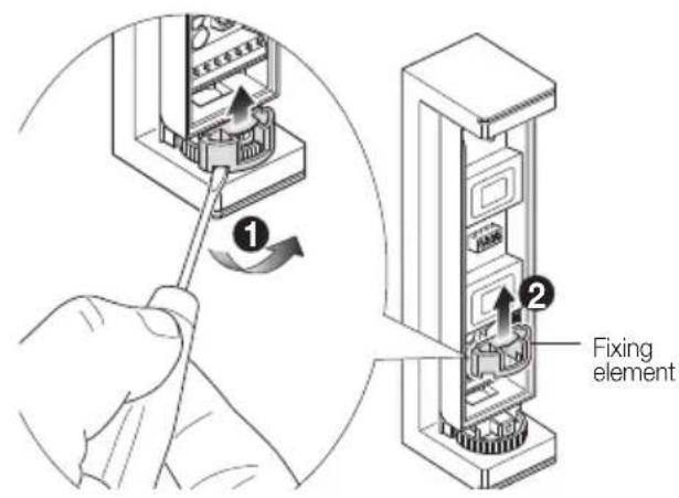
Installation
- Keep the upper part of the bracket raised and remove the main unit.
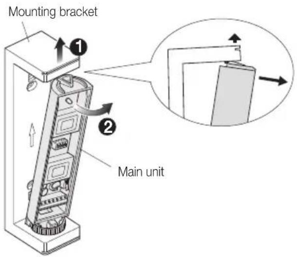
- Insert the cable originating from the wall in the wiring hole on the base of the bracket and then mount the latter onto the wall.
- Pull the cable through the main unit. Raise the upper part of the bracket slightly and mount the main unit onto the bracket.
Installation
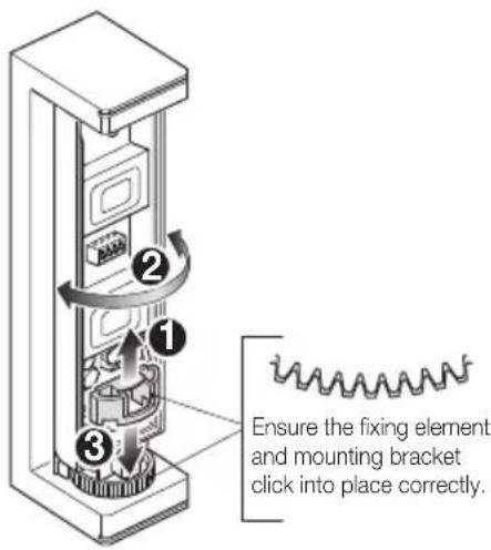
- Determine the horizontal detection angle and connect the fixing element.
natural_image
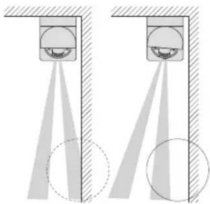
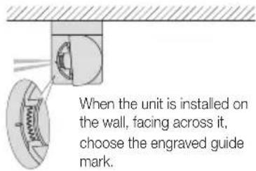
Diagram showing two identical mechanical or optical setups with light beams projecting onto a central component, no text or symbols present.Align the detection area to ensure it is parallel with the wall to reduce interference with the wall.
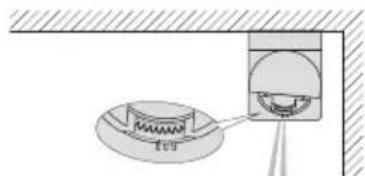
When the unit is installed in a corner, facing forward along the wall, choose the guide mark situated on the opposite side of the wall.
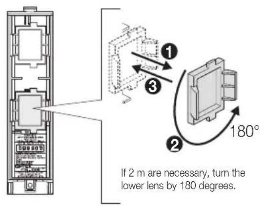
- Determine the detection range.
Detection range 5m
Detection range 2m
- Fasten the cover of the main unit. 9. Perform the walk test (see chap. 8).
natural_image
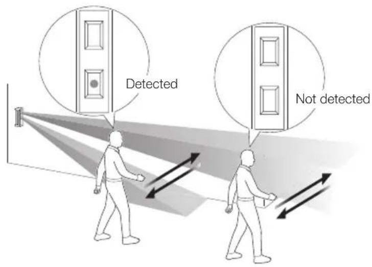
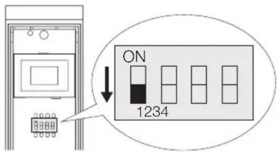
Illustration of a person walking toward a target with directional arrows indicating motion (no text or symbols)N.B. To arrange the walk test, make sure Dip switch 1 is set to "ON" before securing the cover on the main unit.
Walk test - Installation rules - Regulatory compliance
8. WALK TEST
- Set Dip switch 1 (LED) to ON. 2. Check that the LED lights up for 2 s when detection takes place.
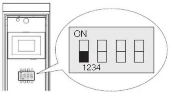
Note: The Dip switch is set to ON by default.
- If it is not necessary for the LED always to light up, set Dip switch 1 (LED) to OFF.
9. INSTALLATION RULES
- Installation must be carried out by qualified persons in compliance with the current regulations regarding the installation of electrical equipment in the country where the products are installed.
• Install the detector in a place where no cause for false alarms is present, such as:
- sunlight and reflections;
- heat sources;
- moving objects or objects which the wind may move.
- The ideal installation height is between 0.8 to 1.2m with the base of the detector always parallel with the ground.
10. REGULATORY COMPLIANCE
LV Directive. EMC directive. RoHS directive.
Standards EN 50130-4, EN 55032, EN 50581.
REACH (EU) Regulation no. 1907/2006 – Art.33. The product may contain traces of lead.
WEEE - User information
The crossed bin symbol on the appliance or on its packaging indicates that the product at the end of its life must be collected separately from other waste. The user must therefore hand the equipment at the end of its life cycle over to the appropriate municipal centres for the differentiated collection of electrical and electronic waste. As an alternative to independent management, you can deliver the equipment you want to dispose of free of charge to the distributor when purchasing a new appliance of an equivalent type. You can also deliver electronic products to be disposed of that are smaller than 25 cm for free, with no obligation to purchase, to electronics distributors with a sales area of at least 400 m². Proper sorted waste collection for subsequent recycling, processing and environmentally conscious disposal of the old equipment helps to prevent any possible negative impact on the environment and human health while promoting the practice of reusing and/or recycling materials used in manufacture.
- ITALIANO
- Installazione
- ENGLISH
- Characteristics - The detector and its parts
- CHARACTERISTICS
- THE DETECTOR AND ITS PARTS
- CONNECTIONS
- Caution:
- Connection to the control unit
- Connections
- Connections - Detector configuration
- Balancing resistor connection.
- DETECTOR CONFIGURATION
- Detector configuration
- LED configuration (Dip switch 1)
- Alarm Output configuration (Dip switch 2)
- PIR Sensitivity configuration (Dip switch 3)
- Anti-masking configuration (Dip switch 4)
- LED SIGNALLING
- COVER DIAGRAMS
- INSTALLATION
- Warnings
- Installation procedure
- Installation
- Walk test - Installation rules - Regulatory compliance
- WALK TEST
- INSTALLATION RULES
- REGULATORY COMPLIANCE
- WEEE - User information
Brand : Vimar
Model : 01740
Category : Motion detector