Excalibur RS-370 - Remote control OMEGA - Free user manual and instructions
Find the device manual for free Excalibur RS-370 OMEGA in PDF.


| Product Type | Remote Start and Security System |
| Brand | Omega |
| Model | Excalibur RS-370 |
| Category | Remote Control (Car Remote Start) |
| Dimensions (approx) | 60 x 30 x 10 mm (2.4 x 1.2 x 0.4 in) |
| Weight (with batteries) | Approx. 30 g (1.1 oz) |
| Power Supply | 2x CR2016 (models 1415/1418) or 1x CR2032 (models 1412/1417) |
| Operating Frequency | 433 MHz (typical) |
| Range | Up to 1000 ft (300 m) open field |
| Remote Start Activation | Programmable: 1 to 4 presses of START button |
| Security Features | Alarm, Anti-Carjacking, Starter Interrupt, Pre-warn detection |
| Outputs | Lock/Unlock, Trunk Release, Horn, Parking Lights, Status |
| Inputs | Brake, Hood, Neutral Safety, Tach Signal |
| Programming | Via Valet button or computer (Omega WebLink) |
| Installation | Professional installation recommended; wires to ignition, starter, etc. |
| Safety Features | Brake pedal shutdown, hood safety, neutral safety, 3D motion sensor (some models) |
| Battery Life (transmitter) | Approx. 1 year under normal use |
| Warranty | 1 year limited |
| Compliance | FCC Part 15 |
Frequently Asked Questions - Excalibur RS-370 OMEGA
User questions about Excalibur RS-370 OMEGA
0 question about this device. Answer the ones you know or ask your own.
Ask a new question about this device
Download the instructions for your Remote control in PDF format for free! Find your manual Excalibur RS-370 - OMEGA and take your electronic device back in hand. On this page are published all the documents necessary for the use of your device. Excalibur RS-370 by OMEGA.
USER MANUAL Excalibur RS-370 OMEGA
1 Choose a discreet mounting location for the module and locations for any accessories (siren, sensors, interface module, etc.). Do not mount the module yet (you might anger the install gods).
2 Identify vehicle connection points and plan harness routing from your mounting location. Avoid any moving vehicle parts or parts that generate heat. Also avoid any sharp metal edges. See wiring details on pages 3-9.
3 Cut system wires to length, prep your harnesses, and make all wire connections to the vehicle.
NOTE: DATA/MUX WIRES ARE SENSITIVE and MUST BE SPLICED DIRECTLY. QUICK TAPS ARE NOT RECOMMENDED.
4 If you are using either of the system's data ports for accessories or modules using DBI protocol, connect these modules now and configure them for DATA MODE.
Perform VEHICLE LEARN (see pages 7 and 10 for instructions). This automatically matches the IGN/ACC/START outputs to the vehicle's ignition switch, auto-detects data protocols, chooses the best engine detection method, decides whether neutral safety circuit is required, and allows you to quickly set engine and transmission types. FASTER THAN PROGRAMMING!
6 Test the system for all functions.
7 Secure the module(s) and harnesses to the vehicle.
8 Reassemble the vehicle.
9 Test the system for all functions again (keep the install gods happy).
WIRE DIAGRAM: CENTER OF THIS BOOKLET FEATURE CHART: BACK COVER
Table Of Contents
Installation Considerations ...... 3
6 Pin Main Wire Harness.... 3
Red & Red/White Wires - Constant Power (+) Input 3
Pink Wire - IGNITION/ACC/START (+) Input/Output.... 3
Orange Wire - ACCESSORY/IGN/START (+) In/Out 4
Violet Wire - Start (+) Input/Output 4
Pink/White Wire - IGNITION/ACC/START (+) In/Out 4
14 Pin Secondary Wire Harness....4
Black Wire - System Ground (-) Input 4
Orange Wire - Status/Anti-grind (-) Output 4
Brown/Red Wire - Brake Pedal (+) Input 4
Black/White Wire - Neutral Safety (-) Input 5
Violet/White Wire - Tach Signal Input 5
Brown Wire - Horn (-) Output 5
White Wire - Flashing Light (+) Output 5
White/Black Wire - Flashing Light (-) Output 5
Gray Wire - Hood Trigger (-) Input....5
14 Pin Secondary Wire Harness (cont'd) 8
Yellow - Alarm Ignition Control (+) Output 8
White/Blue Wire - Remote Start Activation (-) Input 8
Lt. Green/Red Wire - OEM Alarm Arm (-) Output 8
Lt. Green/Black Wire - OEM Alarm Disarm (-) Output 8
Red/White Wire - Trunk Release / CH2 (-) Output 8
Green & Black Data Ports 8
3 Pin Satellite Relay Port (RED) 9
3 Pin Door Lock/Unlock Port (RED)....9
Status Lights....9
Valet / Programming Button 9
Window Mount Antenna Module 10
Tach Programming.... 11
Programming Transmitters.... 11
Programming Features 11
This device complies with FCC Rules part 15. Operation is subject to the following two conditions, (1) This device may not cause harmful interference and, (2) This device must accept any interference that may be received, including interference that may cause undesired operation.
The manufacturer is not responsible for any radio or TV interference caused by unauthorized modifications to this equipment. Such modifications could void the user's authority to operate the equipment.
BEFORE STARTING THE INSTALLATION, READ THIS ENTIRE MANUAL TO DETERMINE INSTALLATION REQUIREMENTS
• VERIFY EACH CIRCUIT WITH A DIGITAL MULTIMETER
• IDENTIFY REQUIRED CIRCUITS FOR THE VEHICLE
• TAPE OFF OR REMOVE ANY UNUSED WIRING TO PREVENT POSSIBLE SHORT CIRCUITS
- ONLY ACTIVATE THE REMOTE START FUNCTION IN A WELL VENTILATED ENVIRONMENT
• AFFIX THE UNDERHOOD WARNING STICKER
- AVOID ANY AIRBAG CIRCUITS, USUALLY INDICATED BY A YELLOW SLEEVE OR JACKET AROUND THE WIRING
6 Pin Main Wire Harness
Most of the main wiring harness connections are high amperage circuits so it is recommended to direct splice, solder, & adequately insulate each connection. Many of these connections are made at the vehicle's ignition switch so be sure to properly route the harness away from anything that could compromise the wire insulation. The goal is to mimic the ignition switch. Keep this in mind when deciding which ignition & accessory circuits to power.
NOTE: A low current harness for newer vehicles is available. It has 18 gauge, 100% copper wires and the RED & RED/WHITE wires are fused at 10A each. Order P/N: H-RS6BLC
RED & RED/WHITE WIRES - CONSTANT POWER (+) INPUT
REQUIRED. These wires provide the constant positive 12v power supply for the system's operation. CONNECTION: Connect these to a constant +12 volt supply with sufficient amperage for remote starting. The +12v supply to the ignition switch is ideal. Some vehicle's have low amperage ignition switches in which case you would need to find a power supply at a fuse block or at the vehicle's battery. Fuse these wires within 6 inches of the connection to the vehicle. The two 30AMP fuses in the harness protect the system module, NOT THE VEHICLE. It is ideal to have a separate supply for each wire but, if the chosen supply is sufficient enough, you can combine both wires at the same point.
PINK WIRE - IGNITION/ACC/START (+) INPUT/OUTPUT
REQUIRED. This connection is required & is critical to the operation of the system. It is an “IGNITION ON” input when the ignition key is turned on. By default, it is the primary ignition output for remote start operation. It turns on when remote start is activated & stays on during engine cranking for the entire remote start sequence. CONNECTION: Use any IGNITION, ACCESSORY, or secondary START circuit in the vehicle. This wire is defaulted for IGNITION output though it may change through the VEHICLE LEARN process (p.10) to match the connected vehicle circuit.
6 Pin Main Wire Harness (cont'd)
ORANGE WIRE - ACCESSORY/IGN/START (+) IN/OUT
This circuit is designed to power additional IGNITION, ACCESSORY, or START circuits. By default, it functions as an ACCESSORY output & turns on when remote start is activated (slightly earlier than the ignition output), turns off during engine cranking, & turns back on for the remainder of the remote start operation.
CONNECTION: Use any IGNITION, ACCESSORY, or secondary START circuit in the vehicle. This wire is defaulted for ACCESSORY output though it may change through the VEHICLE LEARN process (p.10) to match the connected vehicle circuit.
VIOLET WIRE - START (+) INPUT/OUTPUT
This output supplies positive voltage to the vehicle's starter circuit. If using an anti-grind, be sure this is connected on the starter side of the interrupt.
CONNECTION: The starter circuit is typically found at the ignition switch. The proper circuit will show +12v only when the ignition key is in the START position.
PINK/WHITE WIRE - IGNITION/ACC/START (+) IN/OUT
This circuit is designed to power additional IGNITION, ACCESSORY, or START circuits. By default, it functions as an IGNITION output. It turns on when remote start is activated, stays on during engine cranking, & for the entire remote start operation.
CONNECTION: Use any IGNITION, ACCESSORY, or secondary START circuit in the vehicle. This wire is defaulted for IGNITION output though it may change through the VEHICLE LEARN process (p.10) to match the connected vehicle circuit.
14 Pin Secondary Wire Harness
REQUIRED. This input provides negative ground for all system operations.
CONNECTION: Using a properly sized ring terminal, connect this wire to the vehicle's chassis. Using an existing bolt is preferred but make sure that the connection point is clean and free of dirt, grease, or paint. Bright shiny metal at the connection point is desired.
ORANGE WIRE - STATUS/ANTI-GRIND (-) OUTPUT
This provides 500mA negative ground while the alarm is armed and/or during remote start for anti-grind operation. The operation is selectable with installer feature #16.
CONNECTION: This wire is connected to the orange input wire on an optional start interrupt relay.
BROWN/RED WIRE - BRAKE PEDAL (+) INPUT
REQUIRED. This input is a critical safety circuit which disables the remote start operation whenever the brake pedal is pressed.
CONNECTION: Connect this to the brake switch wire that shows +12 volts when the brake pedal is pressed.
BLACK/WHITE WIRE - NEUTRAL SAFETY (-) INPUT
REQUIRED. This input is a critical safety circuit which allows remote start operation whenever the gear selector is in park or neutral (automatic transmission), or when the parking brake is applied (manual transmission). Remote start will not operate unless this wire sees chassis ground.
CONNECTION (Automatic Transmission): Connect this to the neutral safety switch wire that shows (-) ground when the gear selector is in the park and neutral positions.
CONNECTION (Manual Transmission): Connect this to the parking brake switch wire that shows (-) ground when the parking brake is applied.
VIOLET/WHITE WIRE - TACH SIGNAL INPUT
This input provides the engine's RPM signal to the remote start. This is typically the most reliable form of engine detection. To use the tach wire, you must change installer feature #3 to the tach wire setting.
CONNECTION: This can be connected to any trigger wire for an ignition coil, fuel injector, or the signal to the tachometer in the dash. Use a digital multimeter set for AC volts to test. The appropriate wire will read between 1-6 volts AC and will increase as the engine RPM increases.
BROWN WIRE - HORN (-) OUTPUT
This output provides a 1 amp negative output to operate the vehicle's horn.
CONNECTION: Connect this wire to the vehicle's horn circuit. If the vehicle's circuit is something other than negative, you will need to use a relay to convert this output.
WHITE WIRE - FLASHING LIGHT (+) OUTPUT
This output provides a 10 amp positive output to flash the vehicle's parking lights (typically). If the vehicle has a low current negative parking light circuit, use the WHITE/BLACK wire instead.
CONNECTION: Connect this wire to the vehicle's positive parking light circuit. It will show +12 volts when the parking lights are on. BE SURE NOT TO CONNECT TO THE DIMMER CIRCUIT WHICH WILL CHANGE VOLTAGE AS YOU TURN THE DIMMER KNOB.
WHITE/BLACK WIRE - FLASHING LIGHT (-) OUTPUT
This output provides a 250mA negative output to flash the vehicle's parking lights. If the vehicle has a positive parking light circuit, use the WHITE wire instead.
CONNECTION: Connect this wire to the vehicle's negative parking light circuit. It will show ground when the parking lights are on. BE SURE NOT TO CONNECT TO THE DIMMER CIRCUITWHICH WILL CHANGE RESISTANCE TO GROUND AS YOU TURN THE DIMMER KNOB.
GRAY WIRE - HOOD TRIGGER (-) INPUT
REQUIRED. This is a critical safety circuit that prevents remote start functions while the hood is opened. It also monitors the doors in manual transmission mode.
CONNECTION: Connect this wire to the OEM hood switch or light. It will show ground when the hood is opened. You can also use the included pin switch.
(continued on page 8)
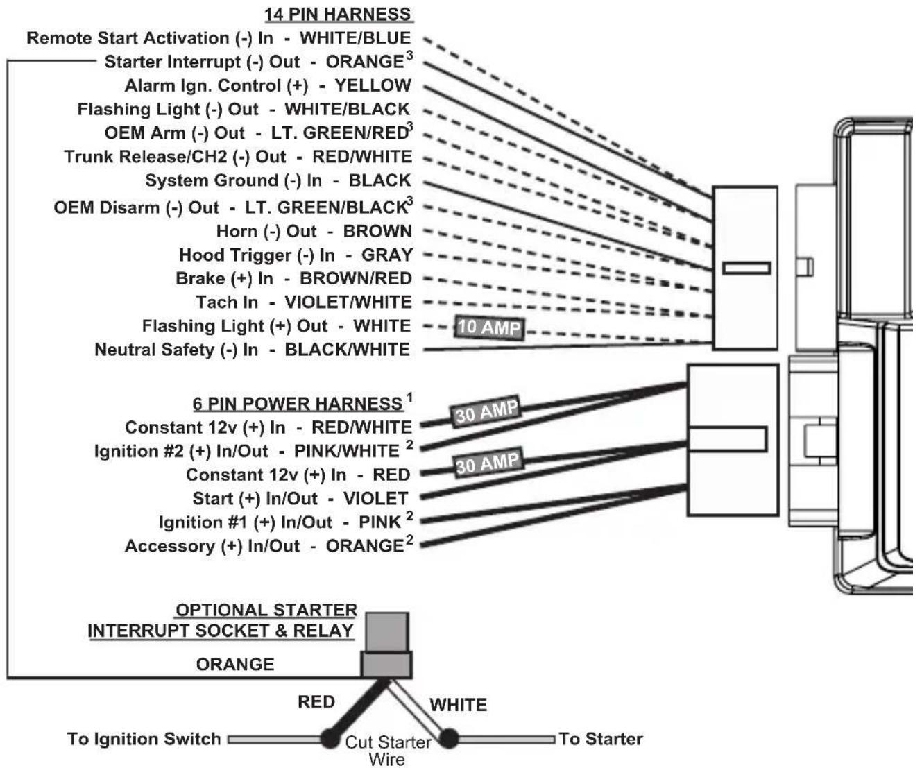
flowchart
graph TD
    A["Remote Start Activation (-) In - WHITE/BLUE"] --> B["Starter Interrupt (-) Out - ORANGE³"]
    B --> C["Alarm Ign. Control (+) - YELLOW"]
    C --> D["Flashing Light (-) Out - WHITE/BLACK"]
    D --> E["OEM Arm (-) Out - LT. GREEN/RED³"]
    E --> F["Trunk Release/CH2 (-) Out - RED/WHITE"]
    F --> G["System Ground (-) In - BLACK"]
    G --> H["OEM Disarm (-) Out - LT. GREEN/BLACK³"]
    H --> I["Horn (-) Out - BROWN"]
    I --> J["Hood Trigger (-) In - GRAY"]
    J --> K["Brake (+) In - BROWN/RED"]
    K --> L["Tach In - VIOLET/WHITE"]
    L --> M["Flashing Light (+) Out - WHITE"]
    M --> N["Neutral Safety (-) In - BLACK/WHITE"]

    O["6 PIN POWER HARNESS¹"] --> P["Constant 12v (+) In - RED/WHITE"]
    P --> Q["Ignition #2 (+) In/Out - PINK/WHITE²"]
    Q --> R["Constant 12v (+) In - RED"]
    R --> S["Start (+) In/Out - VIOLET"]
    S --> T["Ignition #1 (+) In/Out - PINK²"]
    T --> U["Accessory (+) In/Out - ORANGE²"]

    V["OPTIONAL STARTER INTERRUPT SOCKET & RELAY"] --> W["ORANGE"]
    W --> X["To Ignition Switch"]
    X --> Y["Red"]
    W --> Z["White"]
    Z --> AA["Cut Starter Wire"]
    AA --> AB["To Starter"]
WIRE LEGEND
HARD WIRE CONNECTION REQUIRED

FUNCTION SUPPORTED VIA DATA PORTS
NOTES
- LOW CURRENT HARNESS P/N: H-RS6BLC Available for vehicles with less than 20A ignition switches.
- Learning output - see Vehicle Learn Procedure
- Programmable output - see feature chart
VEHICLE LEARN PROCEDURE
- Connect any interface module(s) to the data port(s) and set for data mode.
- Turn the ignition key ON (do not start)
- Activate remote start
System will chirp/flash lights to indicate engine type (Default: 1x = Gasoline)
- Press valet to change engine type:
1 chirp=Gasoline, 2 chirps=Diesel 15,
3 chirps=Diesel 20,4 chirps=Diesel 30
-
Start the engine with the ignition key
-
Turn the ignition key OFF
System will chirp/flash lights equaling the # of IGN/ACC/START circuits detected (Max: 4x)
-
Within 20 seconds of Step 6, Activate remote start. Wait until engine is running and LED is flashing slow.
-
OPTIONAL: To enable Manual Transmission Reservation mode, release and set parking brake again.
System should chirp/flash lights 1x.
- TO SAVE SETTINGS: Shut down RS by pressing the BRAKE pedal.
TO CANCEL/START OVER: Shut down RS by remote or input wire.
\~ See Page 10 For Full Details \~
14 Pin Secondary Wire Harness (cont'd)
MANUAL TRANSMISSION CONNECTION: The Gray wire also serves as a door pin input (must see all doors) which is required to perform the “manual transmission setup procedure” (detailed in the operation guide). Diode isolate the hood input from the door input using two 1 or 2 amp diodes facing the cathodes (stripes) towards the vehicle wires. If the vehicle’s door pin wire is positive, you must invert the signal with a relay.
YELLOW - ALARM IGNITION CONTROL (+) OUTPUT
This output controls the ignition input to an outboard aftermarket alarm or keyless entry. When remote start is activated, this wire prevents the keyless/alarm from receiving an ignition ON input to allow for keyless entry operation. Otherwise, it's a direct pass through of the ignition circuit.
CONNECTION: Connect this wire directly to the outboard keyless entry/alarm's ignition input wire.
WHITE/BLUE WIRE - REMOTE START ACTIVATION (-) INPUT
This input will activate the system's remote start function when it receives a negative pulse. Another pulse during remote start operation will turn off the remote start.
CONNECTION: Connect this wire to any device that you desire to activate the remote start feature. It requires a negative pulse input.
LT. GREEN/RED WIRE - OEM ALARM ARM (-) OUTPUT
This output provides a 250mA negative pulse when remote start is turned off and when the system's alarm is armed.
CONNECTION: Connect this wire to the vehicle's OEM alarm arm circuit. Typically, it will show ground when the door cylinder key is turned to the lock position.
LT. GREEN/BLACK WIRE - OEM ALARM DISARM (-) OUTPUT
This output provides a 250mA negative pulse when remote start is activated and when the system's alarm is disarmed.
CONNECTION: Connect this wire to the vehicle's OEM alarm disarm circuit. Typically, it will show ground when the door cylinder key is turned to the unlock position.
RED/WHITE WIRE - TRUNK RELEASE / CH2 (-) OUTPUT
This output provides a 250mA negative output when the trunk release/CH2 function is activated by the controller. The output will remain as long as the controller button(s) is held.
CONNECTION: Connect this wire to the vehicle's existing trunk release switch if it is a low current negative circuit. If the circuit is a high current ground or a positive circuit, the use of a relay is required.
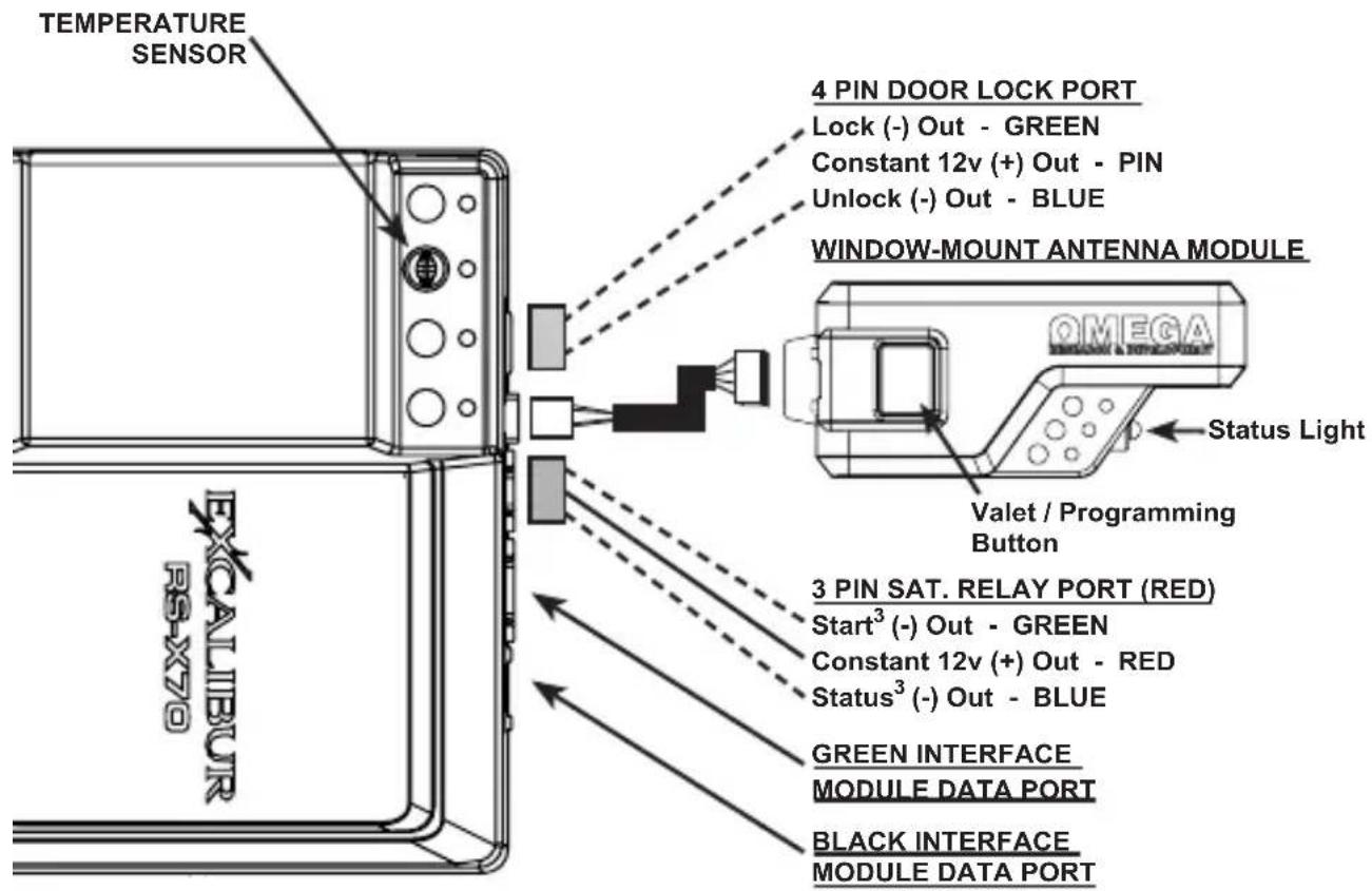
Green & Black Data Ports
These ports provide a direct digital interface for any interface module, or other accessories, using either the DBI protocol or iDatalink protocol. UPON THE FIRST REMOTE START ATTEMPT, THE PORT WILL AUTO-DETECT WHICH PROTOCOL TO USE. MAKE SURE ANY CONNECTED DEVICE IS PROPERLY CONNECTED
AND PROGRAMMED BEFORE HAND. The Black port allows firmware
flashing and feature programming via www.omegaweblink.com.
GREEN WIRE - START (-) PROGRAMMABLE OUTPUT
This output provides a 250mA negative pulse when the large VIOLET start wire is active. It can also be programmed for PULSE AFTER START, STATUS, or DOME-LIGHT SUPERVISION. See installer programmable feature #5.
CONNECTION: If a negative start output is needed, connect this directly to the vehicle's negative starter circuit. Otherwise, use a relay to convert this to a high current circuit.
RED WIRE - CONSTANT (+) OUTPUT
This output provides a 500mA positive output to drive added relay coils.
BLUE WIRE - STATUS (-) PROGRAMMABLE OUTPUT
This provides a 250mA negative output slightly before & during the primary ignition output. This output is programmable. See installer feature #6. CONNECTION: This is typically used to activate immobilizer bypass modules. Connect it directly to the module's activation input.
3 Pin Door Lock/Unlock Port (RED)
GREEN WIRE - LOCK (-) OUTPUT
This provides a 0.8 second 250mA negative pulse for any locking operations. The pulse timing is programmable by installer feature #8.
CONNECTION: Connect this to the vehicle's lock circuit for negative pulse systems. Otherwise, a doorlock interface and/or relays are required to convert the output.
CENTER PIN (EMPTY) - CONSTANT (+) OUTPUT
This output provides a 500mA positive output to drive the positive pin of added relay coils. It is used for Omega prewired doorlock interfaces. BLUE WIRE - UNLOCK (-) OUTPUT
This provides a 0.8 second 250mA negative pulse for any unlocking operations. The pulse timing is programmable by installer feature #8.
CONNECTION: Connect this to the vehicle's "all door" unlock circuit for negative pulse systems. Otherwise, a doorlock interface and/or relays are required to convert the output.
Status Lights
All Models Except The RS-170: The status light is built into the window mount antenna. It is best for these to be highly visible for maximum visual theft deterrence. RS-170: This system includes a separate status light/valet button combo. It can be mounted in a 9mm hole in the dash.
Valet / Programming Button
Most Models: The valet button is built into the window mount antenna. RS-170: The valet button is built into the status light.
Window Mount Antenna Module
Be sure to clean the glass before adhering the antenna. Mount it high in the windshield avoiding metal parts of the vehicle. Metal based window tint can decrease performance. Route the harness to the antenna module avoiding sharp objects that could compromise the harness jacket.
3D Motion Sensor
Some models are equipped with a motion sensor that provides added protection for remote start by shutting down the engine if motion is detected during the START output. This is ideal for manual transmission vehicles and eliminates the need for performing ‘manual transmission setup’ by the user. If the sensor is present, a “3D” logo will be on the antenna case.
Vehicle Learn
Vehicle Learn is a procedure that allows you to quickly configure all vehicle dependant features. It also serves as a diagnostic tool for your IGN/ACC/START output connections on the main power harness. It's much faster than programming, saving you valuable time, & helps you discover critical mistakes.
VEHICLE LEARN WILL:
- Detect the function of the PINK, PINK/WHITE, and ORANGE wires to automatically change the outputs to match the vehicle.
- Diagnose the PINK, PINK/WHITE, ORANGE, & VIOLET wire connections.
- Let you quickly choose engine type
- Auto-select Data-tach, tach wire, or tachless modes.
• Auto-select data port protocols - Save tons of time in the bay!
BEFORE YOU BEGIN:
- Make all wire connections
- Connect any accessories/modules to the data ports.
If you are using an interface module/bypass kit, make sure it is in "DATA MODE" and programmed to the vehicle. - Set the parking brake if it is connected to the BLACK/WHITE wire.
Step 1: Turn the ignition key ON (do not start)
Step 2: Activate remote start by the remote, input activation wire, or smartphone control. The system will chirp/flash lights to indicate engine type (Default: 1x = Gasoline).
Step 3: Press valet to change engine type, if needed:
The system will chirp/flash lights to confirm each selection. 1 chirp=Gasoline, 2 chirps=Diesel 15, 3 chirps=Diesel 20, 4 chirps=Diesel 30
Step 4: Start the engine with the ignition key
Step 5: Turn the ignition key OFF
The system will chirp/flash lights the # of IGN/ACC/START circuits detected (Max: 4x). EXAMPLE: If you connected the PINK, VIOLET, & ORANGE wires, the system should chirp 3x. If it only chirps 2x, one connection has a problem and should be checked. Then start over at Step 1 to retest.
Step 6: Within 20 seconds of Step 5, Activate remote start. Wait until engine is running and LED is flashing slow.
- The system will poll both data ports for modules using the DBI protocol. If they do not respond, it will automatically switch to iDatalink protocol.
- After the engine is running, the system will look for data tach & tach wire availability. If detected, the system will switch to that method. If not, it will remain in tachless-hi.
Step 7: OPTIONAL: To enable Manual Transmission Reservation mode, release and set the parking brake. (The BLACK/WHITE wire must be connected to the parking brake.)
System should chirp/flash lights 1x.
Step 8: TO SAVE SETTINGS: Shut down RS by pressing the BRAKE pedal.
This disables VEHICLE LEARN (installer feature #2).
TO CANCEL/START OVER: Shut down RS by remote or input wire.
Tach Programming
The vehicle's tach signal must be learned for proper operation. After making the tach wire connection, change installer feature #3 to "Tach Wire" & perform the following steps:
Step 1 Turn the ignition key "ON"
Step 2 Within 5 seconds, press the brake pedal 5 times. (the siren will chirp 5 times)
Step 3 Start the engine. The status lights will turn on indicating it has learned the current tach signal. If it does not light, check your tach connection and start over.
Step 4 If the engine has a high idle at startup, it may be necessary to allow the idle to "settle" to around 700 RPM. If needed, you can press the valet button 1 time to resample the tach signal.
The status light will flash off then back on once the signal has been resampled.
Step 5 Turn the ignition key "OFF".
Programming Transmitters
Step 1 Have all transmitters which are to operate the system at hand. Then, turn the ignition "on".
Step 2 Within 5 seconds of turning on the ignition, press the Valet button 5 times. The horn will briefly sound & the status light will turn on, confirming that for the next 10 seconds the system is ready to learn a transmitter/controller code.
Step 3 Press the “lock” button (press “start” on 1-button models) on each transmitter one at a time. The system will chirp the horn once to confirm that each was learned. The transmitter’s other button’s are automatically assigned at this point. If a code is not received within a 10 second period, the learning process will end, as indicated by another horn honk.
Step 4 Turn the vehicle's ignition "off".
Programming Features
A matrix of all programmable features and their options are on the next page. For feature explanations, refer to the operation manual. Use the procedure below to make changes.
NOTE: You can program features via your computer with Omega Weblink.
Visit www.omegaweblink.com for more information
Step 1 Turn the ignition key "ON", then "OFF"
Step 2 Within 5 seconds of step 1, press the valet button 5 times to access user features (Press 10 times to access installer features). (The siren/horn will sound and the status light will turn on)
Step 3 Within 10 seconds of step 2, press the valet button the number of times corresponding with the desired feature's number. (The siren/horn will chirp equal to the selected feature)
Step 4 4-button MODELS: Press the transmitter button that matches your desired setting.
1-button MODELS: Press the transmitter button (OR turn on the ignition and press the brake pedal) the number of times that matches your desired setting. (The siren/horn will chirp matching the selected setting)
Step 5 If you wish to change more features, repeat steps 3 & 4 at this time.
Step 6 To exit programming, turn the ignition key "ON" then "OFF". Or, it will exit automatically after 10 seconds of no activity.
RESTORING FEATURE SETTINGS TO FACTORY DEFAULT:
Step 1 Enter Intaller Feature programming (DO NOT SELECT ANY FEATURES)
Step 2 4-button MODELS: Press LOCK + UNLOCK (or BRAKE x 5)
1-button MODELS: Press the START button 5 times (or BRAKE x 5)
(The siren/horn will sound to indicate reset and exit programming)
| User Feature Programming: Ignition on, off, press valet 5 times | ||||||
| # Feature | Lock Button (Brake 1x) | Unlock button (Brake 2x) | Trunk button (Brake 3x) | Start button (Brake 4x) | Lock + Unlock (Brake 5x) | Trunk + Start (Brake 6x) |
| 1 Remote Start Run Time 3 min | 15 min 20 min | |||||
| 2 Flashing Light Confirmations | Unlock: ON RS: ON | Unlock: ON RS: Flash | Unlock: Flash RS: ON | Unlock: Flash RS: Flash | ||
| 3 Confirmation Chirp Volume Low Med | d-Low | High | ||||
| 4 BROWN Wire: Siren/Pulsed Horn Pulse LOW Off | Off | MED Pulse HI Ste | ady Siren Random | |||
| 5 Ignition Lock / Unlock | Ign On = Lock | Ign. Off = Unlock | Lock + Unlock | |||
| 6 Door Open Bypass for Feat. #5 | ||||||
| 7 Unlock w/ Trunk Release | On | |||||
| 8 RS Activation (Remote) | Start x 1 | Start x 2 | Start x 3 | Start x 4 | ||
| 9 Last Door Arming | Off | k* On w/ Lock* | ||||
| 10 Automatic Rearming | Off | On w/o Lock | On w/ Lock | Enhanced | ||
| 11 Confirmation Chirps | Siren + Horn | Siren Only | Horn Only | On Demand | Off | |
| 12 Anti-Carjacking | Ignition | Door* | Ignition + Door* | Off | ||
| 13 Override Code | See operation guide for programming instructions. DEFAULT: 1,0 | |||||
| 14 Ignition Override | On | |||||
| 15 Alarm Trigger Duration | 30 sec | 60 sec | 90 sec | 120 sec | ||
| 16 Arming Delay | 3 sec | 15 sec | 30 sec | 45 sec | ||
| 17 Open Door Warn Upon Arming | On | Off | ||||
| Installer Feature Programming: Ignition on, off, press valet 10 times | ||||||
| 1 RS Activation (WHITE/BLUE wire) | 1 Pulse | 2 pulses | 3 pulses | 4 pulses | ||
| 2 Vehicle Learn | Enabled | Disabled | ||||
| 3 Engine Detection | Prog. Voltage | Voltage | Tach Wire | Data-tach | Crank Only | |
| 4 Gasoline or Diesel Engine | Gasoline | 15 sec Diesel | 20 sec Diesel | 30 sec Diesel | ||
| 5 Sat. Port GREEN Wire | Dome Light | Start | Ignition | Accessory | Status | Light Flash |
| 6 Sat. Port BLUE Wire | Ignition | 0.8 sec Defrost Pulse | 10 min Defrost Pulse | Pulse After Engine Off | Horn | |
| 7 Crank Time | 0.75 sec | 1 sec | 1.5 sec | 2.25 sec | 3 sec | Average |
| 8 Door Lock/Unlock Outputs | 0.8 sec | 3 sec | Double Unlock | Total Closure | ||
| 9 Remote Start Lock Control | Off | start | Unlock before Start | Unlock Before & Lock After | Lock After Engine Off | |
| 10 Turbo Timer | Off | 1 min | 2 min | 3 min | ||
| 11 Manual Trans. Reservation | On | |||||
| 12 Data Port Protocol | Green: DBI Black: DBI | Green: iData Black: iData | Green: DBI Black: iData | Green: iData Black: DBI | ||
| 13 Alarm Functions | On | Off | Off-Unlock Only | Sensor Detect | ||
| 14 Pulse Ign. on Disarm | On | |||||
| 15 Lock On Prewarn | On | |||||
| 16 Starter Interrupt | Alarm Only | Anti-grind Only | Alarm/Anti-Grind | Automatic | ||
| 17 Low Temp Crank Extender | 0 ms | 200 ms | 300 ms | 400 ms | ||
| 18 OEM Arm/Disarm or CH. 4/5 | Arm/Disarm | Arm/CH5 Pulse | CH4 Pulse/ Disarm | CH4 Pulse/ CH5 Pulse | CH4 Latch/ Disarm | CH4 Latch/ CH5 Pulse |
| 19 BROWN Wire | Horn | trunk Release | Pulse After Start | |||
| 20 Low Current Mode | On | |||||
FEATURE SETTING KEY:
Default Setting
Installer Feature 13 (Alarm Functions) must be ON
* Door status required from external interface module or DATA sensor w/ analog inputs.
EXCALIBUR REMOTE START & SECURITY PERFECTED
AL-1670-B RS-375-3DB RS-375-3D RS-370
Temporary cover. Final cover is in a separate file.
Table Of Contents
Controller Overview....3
The Controller....3
Controller Functions 3
Other Remote Start Features 8
Low Voltage & High/Low Temp Automatic Starting 8
Turbo Timer Mode 8
Pit-Stop Mode....8
XL Pit-Stop Mode 8
Manual Transmission Starting 9
Security System Features 9
Last Door Arming....9
Automatic Rearming....9
Pre-Warn Detection 9
When The System Triggers.... 10
Using The Valet Button.... 10
Emergency Override 10
SecureCode 10
Valet Mode....11
The Status Light 11
Anti-Carjacking Protection....12
Programming Controllers/Transmitters.... 13
Programming Features.... 13
User Programmable Features 14
Installer Programmable Features 19
THE CONTROLLER
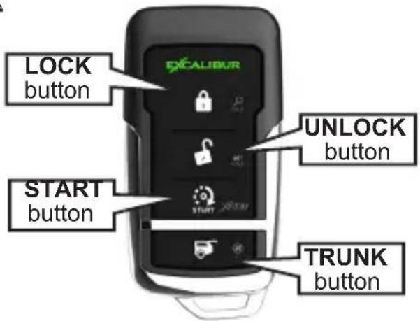
| System Controller(s) Battery | ||||
| AL-1670-B 1415-03 (x2) CR-2016 (2 per controller) | ||||
| RS-375-3DB 1412-03 (x2) CR-2032 (1 per controller) | ||||
| RS-370-3D 1412-03 (x2) CR-2032 (1 per controller) | ||||
| RS-370 1415-03 | 1416-07 CR | -2016 (x2) | CR-2032 (x1) | |
Transmitter battery replacement:
Remove the small screw from the lower back case, and separate the transmitter halves. Replace the batteries and reassemble the transmitter case.
Call your dealer or visit www.caralarm.com to order replacement controllers.

IF YOUR ANTENNA HAS THE ECHO 2-WAY READY LOGO, YOU CAN UPGRADE TO 2-WAY JUST BY ADDING A 2-WAY CONTROLLER. ASK YOUR DEALER ABOUT: MODEL 1510-03 (LCD 2-WAY) MODEL 1511-03 (LED 2-WAY)
Controller Functions
LOCK / ARM: Press and release the LOCK button.
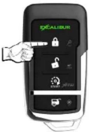
- THE SIREN WILL CHIRP & THE PARKING LIGHTS WILL FLASH ONCE.
Controller Functions (cont'd)
UNLOCK / DISARM: Press and release the UNLOCK button.
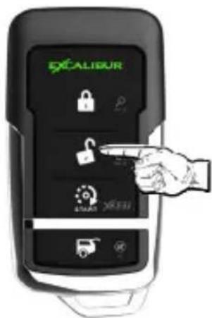
• THE SIREN WILL CHIRP TWICE & THE PARKING LIGHTS WILL FLASH TWICE.
REMOTE START: Press and release the START button twice within 5 seconds (see user feature #8 to change).
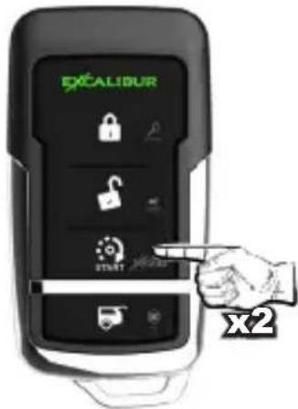
- THE PARKING LIGHTS WILL FLASH ONCE AND THE STATUS LIGHT WILL FLASH RAPIDLY.
• THE SYSTEM WILL PROCEED TO START THE ENGINE. -
ONCE THE ENGINE IS RUNNING, THE PARKING LIGHTS WILL TURN ON AND THE STATUS LIGHT WILL FLASH SLOWLY.
-
If the engine stalls, the system will make up to 3 more attempts.
• Each time you park, set the climate controls to give you the desired interior temperature when you use the remote start. - The engine will run for the preset run time (see user feature #1).
Run Time Extender: Press the START button one time during remote start to restart the engine run timer. The timer will restart.
NOTE: This can only be used once per remote start cycle.
- If you decide not to drive your vehicle, you can turn off the remote start using the same method to turn it on (Default = press START twice in 5 seconds).
NOTE: If user feature #8 is programmed for 1 press, the 1st press = Run Time Extender so an additional press is required.
- Upon entering the vehicle during remote start mode, turn the ignition key to the "ON/RUN" position (NOT START!!). When you press the brake pedal, the remote start will turn off allowing the ignition key to take over.
TRUNK RELEASE / CHANNEL 2: Press the TRUNK button for 3 seconds.
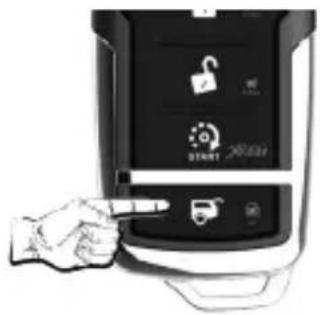
- THE SYSTEM WILL UNLOCK/DISARM AND THE TRUNK WILL OPEN (IF EQUIPPED).
CHANNEL 3: Press and hold the TRUNK & START buttons for 1 second.
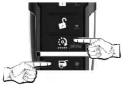
- YOUR SYSTEM WILL ACTIVATE THE CH. 3 OUTPUT. * ONLY AVAILABLE ON -B AND -3DB MODELS
CHANNEL 4: Press and hold the LOCK & TRUNK buttons for 1 second.
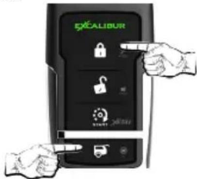
- YOUR SYSTEM WILL ACTIVATE THE CHANNEL 4 OUTPUT.
CHANNEL 5: Press and hold the UNLOCK & START buttons for 1 second
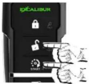
- YOUR SYSTEM WILL ACTIVATE THE CHANNEL 5 OUTPUT.
Controller Functions (cont'd)
PANIC: Press and hold the LOCK or UNLOCK button for 3 seconds.
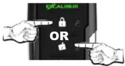
- THE SIREN/HORN WILL SOUND, THE PARKING LIGHTS WILL FLASH, AND THE DOORS WILL LOCK OR UNLOCK DEPENDING WHICH BUTTON IS PRESSED.
SILENT ARM / DISARM: Press and release the TRUNK button twice in 5 seconds.
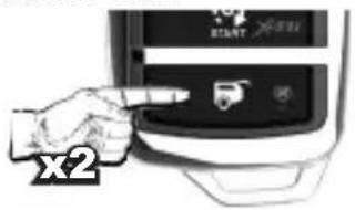
- THE PARKING LIGHTS WILL FLASH, AND THE DOORS WILL LOCK/ARM OR UNLOCK/DISARM DEPENDING ON THE CURRENT SYSTEM STATUS.
SENSOR BYPASS: Press and release the TRUNK button within 5 seconds of locking/arming the alarm system.
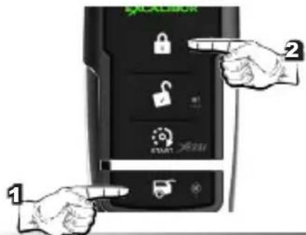
- THE SYSTEM WILL GIVE ONE CHIRP, AFTER LOCKING, TO INDICATE THE SENSOR IS BYPASSED.
LOW VOLTAGE & HIGH/LOW TEMP AUTO START: Press and release UNLOCK, LOCK, START within 5 seconds.
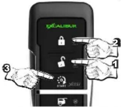
- THE SYSTEM WILL GIVE ONE CHIRP TO INDICATE THE LOW VOLTAGE & HIGH/LOW TEMP AUTO START IS ACTIVATED. - SEE PAGE 8 FOR MORE INFO.
REMOTE VALET: Press LOCK then UNLOCK then TRUNK + START within 5 seconds.
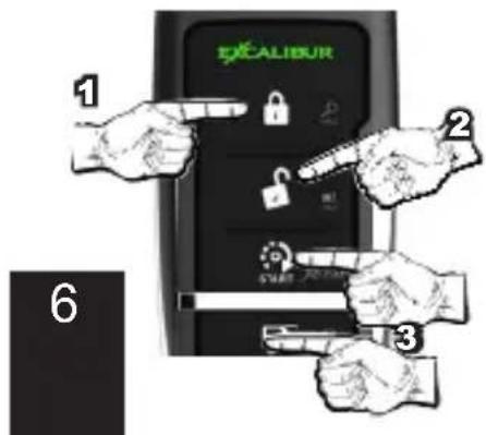
- THE SYSTEM WILL ENTER VALET MODE. SEE PAGE 11 FOR MORE INFO ON VALET MODE. TO EXIT VALET VIA REMOTE, REPEAT THESE STEPS
AUXILIARY FUNCTIONS 1-4:
The actual operation of these functions will vary from car to car. They are designed to operate extra vehicle functions like automatic sliding doors or motorized hatches. Aux 1-4 are virtual outputs only available on certain vehicles when this system is integrated with the vehicle's data network. Consult with your installer to find out if any of these functions are available for your vehicle. If so, confirm each operation with the controller and write each function in the blank spaces provided below.
- Auxiliary 1 Function (____): To activate this function, press and release the TRUNK and START buttons simultaneously).
- Auxiliary 2 Function (____): To activate this function, press and release the LOCK and TRUNK buttons simultaneously).
- Auxiliary 3 Function (____): To activate this function, press and release the UNLOCK and START buttons simultaneously).
- Auxiliary 4 Function (____): To activate this function, press and release the UNLOCK and TRUNK buttons simultaneously).
ECHO 2-WAY READY
IF YOUR ANTENNA HAS THE ECHO 2-WAY READY LOGO, YOU CAN UPGRADE TO 2-WAY JUST BY ADDING A 2-WAY CONTROLLER. ASK YOUR DEALER ABOUT:
MODEL 1510-03 (LCD 2-WAY)
MODEL 1511-03 (LED 2-WAY)
LOW VOLTAGE & HIGH/LOW TEMP AUTOMATIC STARTING
This feature will automatically start the engine if the vehicle battery drops below 11.5 volts or the interior temperature goes above or below the pre-programmed threshold.
Programming The Activation Low Temperature Threshold:
- Turn the ignition switch “on”, then “off” (engine not running), and within 5 seconds press the valet switch twice. The siren will chirp 3 times, within 5 seconds press the valet switch equal to the desired low temperature remote start threshold.
1 press = 0 degrees F - 1 chirp confirmation
2 presses = 15 degrees F - 2 chirps confirmation
3 presses = 32 degrees F - 3 chirps confirmation
Programming The Activation High Temperature Threshold:
- Turn the ignition switch “on”, then “off” (engine not running), and within 5 seconds press the valet switch three times. The siren will chirp 4 times, within 5 seconds press the valet switch equal to the desired high temperature remote start threshold.
1 press = 75 degrees F - 1 chirp confirmation
2 presses = 90 degrees F - 2 chirps confirmation
3 presses = 105 degrees F - 3 chirps confirmation
4 presses = 120 degrees F - 4 chirps confirmation
- You must activate these features each time you park your car to use them.
Activation Using The Valet Switch
- Turn the ignition switch “on”, then “off” (engine not running), and within 5 seconds press the valet switch twice. After a 2 second delay without additional valet button presses, the siren will chirp 3 times activating low battery & low/high temp auto start.
Activation Using The Controller
- Within 5 seconds, press UNLOCK, LOCK, START. The siren/horn will chirp to confirm. These features will operate once every two hours until the ignition key is turned "ON".
TURBO TIMER MODE
It is typically recommended that vehicles equipped with turbocharged engines allow the engine to idle after driving to cool the turbocharger. When Installer Programmable Feature #10 is ON, the system will automatically keep the engine running as follows:
- With the engine running, hold the brake pedal and engage the parking brake. When the brake pedal is released, the system will keep the engine running for the programmed time (1, 2, or 3 minutes).
- Turbo Timer can be bypassed by turning the engine off before engaging the parking brake. If it's already engaged, step on the brake pedal to turn the engine off.
PIT-STOP MODE
This feature allows you to leave your engine running for making quick errands. To use this feature, have the engine running normally from the ignition switch and your foot off the brake pedal. Press the Valet Switch twice; the parking lights will flash and the ignitions will turn on. Turn the key off and the engine will remain running for the programmed run time. Run time extender can be used in this mode.
XL PIT-STOP MODE
This feature allows you to leave your engine running for an extended period of time. To use this feature, have the engine running normally from the ignition switch and your foot off the brake pedal. Press the Valet Switch 6 times; the parking lights will flash and the ignitions will turn on. Turn the key off and the engine will remain running for 12hrs. Run
time extender can be used in this mode allowing a run time up to 24hrs. This is ideal for commercial refrigeration trucks, cleaning vans, vehicles w/ PTO, etc.
MANUAL TRANSMISSION STARTING
Remote starting with a manual transmission requires that you ensure the gear selector is in NEUTRAL. There are 2 available methods.
METHOD #1 - 3D MOTION SENSOR:
Some models are equipped with a 3D motion sensor built into the antenna (optional sensors are available as an upgrade). Whenever remote start is activated, this sensor is monitored for vehicle movement. If the vehicle moves just a few inches when the engine is cranking, it will instantly turn the engine off. This safety feature allows you to enjoy remote start without performing reservation mode as described below.
METHOD #2 - RESERVATION MODE:
For extra safety, installer feature #11 can be turned on which requires you to perform a setup procedure that ensures the transmission was left in neutral when you park your vehicle. This must be performed each time you leave your vehicle to use remote start later. To do so, follow these steps:
1) With the engine running via the ignition switch, hold the brake pedal, apply the parking brake, then release the brake pedal.
2) Use the transmitter as if you were activating remote start (default: press START twice). The status light will start to flash slow.
3) Turn off the ignition key and exit the vehicle, the engine will continue running.
4) Press LOCK on the transmitter. The engine will shut down (unless turbo timer is on) and the status light will flash every 2 seconds (ready to be remote started).
NOTE: Manual transmission starting is canceled if you enter the vehicle after performing the setup procedure.
Security System Features
LAST DOOR ARMING
This system can be configured to arm automatically when all the vehicle's doors are closed (see user feature #9). When this feature is utilized, the siren/horn will chirp once when all of the doors are closed. At that point, it will start a 30 second countdown (indicated by a fast flashing status light). After 30 seconds, the system will arm (and lock the doors if configured to do so). During the 30 second arming delay, if a point of entry is opened, the countdown will pause until all entry points are closed again. Turning ON the ignition key will cancel the last door arming sequence until the key is turned off and the doors are all closed once again.
AUTOMATIC REARMING
This automatically rearms the alarm if the system is disarmed from the remote (see user feature #10). When disarmed by remote, the system will start a 90 second countdown (fast flashing status light) to arm the system. This is useful if the controller accidentally disarms the system when it's kept in a purse or pocket where other items could potentially press the buttons. ENHANCED AUTO REARM allows you to cancel the countdown by pressing UNLOCK a second time within 5 seconds of the first press to disarm the alarm.
PRE-WARN DETECTION
This system's impact sensor is designed, in addition to detecting a full impact, to warn away potential violators when it detects a light impact to the vehicle. The system will respond by chirping the siren/horn 3 times and locking the doors.
Security System Features (cont'd)
WHEN THE SYSTEM TRIGGERS
It will sound the siren/horn and flash the parking lights for 30 seconds (programmable). When disarming after a trigger event, the siren/horn will chirp 4 times and the parking lights will flash 4 times instead of the standard 2 times.
LOCK ON TRIGGER: If a door is opened when the system is triggered, it will wait until the door is closed again, then lock the doors. This feature combats "slim jim" type devices.
STORM SAFE MODE: When the system is triggered, pressing the UNLOCK button will stop the alarm from sounding but will leave the doors locked.
NUISANCE PREVENTION: If the system pre-warns 5 times within 15 minutes, it will bypass the zone for the remainder of the 15 minutes before rearming the pre-warn zone. Additionally, if a full trigger zone is left open, the system will trigger a total of 3 times before bypassing the zone. Once the zone is closed again, it will re-arm that zone.
Using The Valet Button
EMERGENCY OVERRIDE
If you were to lose or break your controller, you'd need to perform an emergency override to disarm the system and use your vehicle. To do so, use the following steps:
STEP 1 - Enter the vehicle (the alarm should sound).
STEP 2 - Turn the ignition key to the "ON" position.
STEP 3 - Press the valet switch (located in the window-mount antenna) once.
NOTE: Enter your SecureCode at this time if programmed via user feature #13 STEP 4 - Turn the ignition key "OFF".
SECURECODE
SecureCode allows you to customize the number of valet presses required to perform an emergency override. This is an extra layer of security that prevents anyone from overriding the alarm even if they have a key to the vehicle. SecureCode has 2 stages with the first requiring 1-9 button valet presses and the second requiring 0-9 valet button presses. This gives you 99 possible combinations. To program a custom SecureCode, please refer to user feature #13 on Page 18.
To perform an emergency override with SecureCode, use the following steps:
STEP 1 - With the system armed, enter the vehicle (the alarm will activate).
STEP 2 - Turn the ignition switch to the "ON" position.
STEP 3 - Within 5 seconds of step 2, press the valet switch to enter the first digit of your programmed code.
STEP 4 - After a few seconds, the siren will stop sounding and chirp once (confirming stage 1). The siren will then continue sounding.
STEP 5 - Now, within 5 seconds of step 4, press the valet switch to enter the second digit of your code. If the code is correct, the alarm will disarm.
If the code is entered incorrectly, you must turn the ignition key OFF, then back ON to try again. Additionally, if 2 failed attempts are made, the alarm will ignore any further attempts for 2 minutes.
VALET MODE
Valet mode completely disables all security & remote start functions. Keyless entry is still operable. To enter valet mode, perform the following steps:
STEP 1 - Disarm the system by remote or by performing an emergency override.
STEP 2 - Press and hold the valet switch for 2 seconds. The system will chirp once and the status light will turn on.
EXITING VALET MODE - Press and release the valet switch once.
The Status Light
The status light, located in the antenna, indicates the system's current status.
SECURITY SYSTEM STATUS
OFF: The alarm is disarmed and not performing any automatic functions.
ON: The alarm is in valet mode.
FLASHING SLOW: The alarm is armed and monitoring all entry points.
FLASHING FAST: One of the automatic arming features is in progress.
AUTOMATIC TRANSMITTER VERIFICATION
Every time you turn on the ignition key, the status light will flash a number of times equal to the number of controllers programmed to the system. This unique security feature combats potential thieves (valet attendant, mechanic, etc.) from adding their own transmitter without your knowledge and accessing your vehicle at a later time.
ALARM ZONE VIOLATION RECALL
If the security system is triggered, upon disarming, the status light will flash a number of times to indicate exactly which zone(s), has been violated. It will store the last 2 violated circuits and continually repeat the flash pattern until the vehicle's ignition key is turned ON.
2 FLASHES: Hood trigger
3 FLASHES: Door trigger
4 FLASHES: Sensor port trigger
REMOTE START STATUS
FLASHING SLOW: The engine was remote started successfully and is running.
FLASHING FAST: The remote start sequence has begun and is in process of starting.
2 FLASHES, PAUSE: The engine is running while the alarm is armed.
REMOTE START DIAGNOSTICS
The remote start system can also indicate which zone caused the last remote start cycle to end. To see this indicator, place the system into alarm valet mode. Immediately after the chirp, the status light will flash to indicate which zone violation occurred.
1 FLASH: The hood was opened.
2 FLASHES: Brake pedal was pressed.
3 FLASHES: Bad tach signal or engine overrev.
4 FLASHES: The neutral safety circuit was triggered.
5 FLASHES: The 3D sensor detected vehicle motion.
6 FLASHES: Received command to stop.
7 FLASHES: The alarm was triggered.
8 FLASHES: Run time expired.
9 FLASHES: Low battery voltage was detected.
Anti-Carjacking Protection
The system is equipped with two separate Anti-Carjacking protection features (ignition, open door, or both). All are programmable, and must be turned on to operate. Once activated, the user has 60 seconds to cancel the Anti-Carjacking protection process (described below). If Anti-Carjacking is not cancelled, 53 seconds after being activated the siren will begin to chirp for 7 seconds to alert the user that the system is about to enter into an alarm condition. The Valet Switch may still be pressed once during this period to cancel the Anti-Carjacking process.
If the Anti-Carjacking process is not cancelled before the 60 second countdown expires, the system will enter an alarm condition, sounding the siren and flashing the parking lights. 30 seconds after this occurs, or should the ignition be turned off in the meantime, the stater interrupt will engage. Once the system enters the alarm condition, it will not respond to the transmitter, nor will the system reset automatically after 60 seconds, and it can only be disengaged by:
Step 1 Turning the vehicle's ignition off.
Step 2 Turning the ignition back on.
Step 3 Within 5 seconds, perform an Emergency Override using the Valet Switch. If the SecureCode has been customized, the correct number of Valet Switch presses must be made.
The different types of Anti-Carjacking protection are:
Ignition Activated Anti-Carjacking activates every time the vehicle's ignition is turned on. The Valet Switch must be pressed within 60 seconds of activating to cancel Anti-Carjacking. This is User Programmable Feature #12.
Door Anti-Carjacking activates when a door is opened after the vehicle is started and the engine is running. The Valet Switch must be pressed within 60 seconds after activation to cancel Anti-Carjacking. This is User Programmable Feature #12.
Programming Controllers/Transmitters
Standard Programming: Using this method to program additional or replacement transmitters does not turn on or otherwise affect the Unauthorized Transmitter Alert (UTA) feature. Before you begin, have all transmitters which are to operate the system at hand.
Step 1 Then, turn the ignition "on".
Step 2 Within 5 seconds of Step 1, press the Valet Switch 5 times. The siren/horn will briefly sound, confirming that the system is ready to learn a transmitter code.
Step 3 Press the LOCK button on each transmitter one at a time. The system will chirp the siren/horn once to confirm that each was learned. If a code is not received within 10 seconds of Step 2, the learning process will automatically exit.
If the Unauthorized Transmitter Alert feature is on, programming a transmitter to the system will activate the “UTA” warning and the extended Status Light indication. For the next 48 hours, the siren/horn will sound a brief series of chirps every time the vehicle’s ignition key is turned on.
Special Programming procedure to turn on the UTA feature: Use this method to program transmitters or optional controllers, and to turn on the Unauthorized Transmitter Alert feature.
Follow the same steps as the Standard Programming, but on any controller being programmed instead of pressing the LOCK button, press the LOCK and the UNLOCK buttons together. This action turns on the Unauthorized Transmitter Alert feature and at the same time programs the controller to operate the system.
Once the Unauthorized Transmitter Alert feature is turned on, the warning will sound for 48 hours after any transmitter programming, including the programming session which was used to turn it on. This feature can only be turned off again by sending the system back to Omega for a reset.
Programming Features
Step 1 Turn the ignition key "ON", then "OFF".
Step 2 Within 5 seconds of step 1, press the valet switch 5 times to access user features (10 times to access installer features).
\~ The siren/horn will sound and the status light will turn on.
Step 3 Within 10 seconds of step 2, press the valet switch the number of times corresponding with the desired feature's number.
\~ The siren/horn will chirp, the status light, and the parking lights will flash equal to the selected feature.
Step 4 Change the feature by pressing the transmitter button that corresponds with the desired setting. The siren/horn will chirp to correspond with the chosen setting.
User Programmable Features
Feature #1 - Remote Start Run Time
3 Minutes (press LOCK to program)
10 Minutes (press UNLOCK to program)
15 Minutes (press TRUNK to program)
20 Minutes (press START to program)
30 Minutes (press LOCK & UNLOCK to program)
This sets the maximum amount of time that the remote start will keep the engine running if it is not shut down by other methods.
Feature #2 - Flashing Light Confirmations
Unlock: ON, RS: ON (press LOCK to program)
Unlock: ON, RS: Flash (press UNLOCK to program)
Unlock: Flash, RS: ON (press TRUNK to program)
Unlock: Flash, RS: Flash (press START to program)
This feature affects the parking light confirmations for system unlock & remote start functions. With the above options, you can select any combination of:
Unlock: Flash - Flashes twice after unlock
Unlock: ON - Flashes twice then stays on for 30 seconds after unlock
RS: ON - Stays on during remote start mode
RS: Flash - Flashes once every 1.5 seconds during remote start mode
Feature #3 - Confirmation Chirp Volume
Low (softest) (press LOCK to program)
Medium Low (press UNLOCK to program)
Medium High (press TRUNK to program)
High (loudest) (press START to program)
This feature allows the choice different chirp volume levels, and when programming it, each selection will be confirmed in the chosen volume making it easy to choose the most suitable setting.
Feature #4 - BROWN Wire Audible Output
Pulsed Horn Low (press LOCK to program)
Pulsed Horn Medium (press UNLOCK to program)
Pulsed Horn High (press TRUNK to program)
Steady Siren (press START to program)
Random (press LOCK & UNLOCK to program)
This changes the BROWN wire's audible output when the alarm is triggered. Steady siren must be selected when using a siren (other horn outputs stay at the Medium setting).
The random option will pulse the horn in a distinct long and short honk routine during the alarm trigger condition. The horn honk options will affect all horn honk outputs used as well as change the BROWN wire's function. If installer feature #6 is set to "Horn" the Brown wire will function as a steady siren when "Random" is selected.
Feature #5 - Ignition Controlled Lock/Unlock
Off (press LOCK to program)
Lock w/ Ignition On (press UNLOCK to program)
Unlock w/ Ignition Off (press TRUNK to program)
Lock And Unlock w/ Ignition (press START to program)
This feature controls the lock/unlock operations when the ignition key is turned on/off,
Feature #6 - Open Door Bypass of Ignition Locking
On (press LOCK to program) Off (press UNLOCK to program)
This feature cancels the automatic locking or unlocking of the vehicle's doors if one of the doors is open when the ignition switch is turned on or off.
Feature #7 - Unlock w/ Trunk Release
On (press LOCK to program) Off (press UNLOCK to program)
“2nd channel” is most commonly used for trunk release, in which case the alarm should also disarm. This feature, when on, configures the system to unlock/disarm when the 2nd channel is activated.
Feature #8 - Remote Start Activation From The Remote
Press START button 1 time (press LOCK to program) Press START button 2 times (press UNLOCK to program) Press START button 3 times (press TRUNK to program) Press START button 4 times (press START to program)
This feature changes how the remote start feature is activated from the remote.
Feature #9 - Last Door Arming
Off (press LOCK to program) On w/o doors locking (press UNLOCK to program) On w/ doors locking (press TRUNK to program)
“Last Door Arming” has the system automatically arm itself every time you exit the vehicle (the complete operation is described on page 8).
Feature #10 - Automatic Rearming
Off (press LOCK to program) On w/o doors locking (press UNLOCK to program) On w/ doors locking (press TRUNK to program) Enhanced auto rearm (press START to program)
"Automatic Rearming", described on page 9, rearms the alarm if accidentally disarmed. Options are to have Automatic Rearming operate with or without also locking the doors when the system does rearm. Enhanced auto rearm allows you to cancel the rearming sequence by pressing unlock a 2nd time after disarming.
Feature #11 - Confirmation Chirps
Siren + Horn (press LOCK to program) Siren Only (press UNLOCK to program) Horn Only (press TRUNK to program) On Demand (siren+horn) (press START to program) Off (press LOCK & UNLOCK to program)
This feature selects whether the siren and/or horn give confirmation chirps. Both outputs will always sound when the alarm system is triggered or in panic mode.
Feature #12 - Anti-Carjacking
Ignition Only (press LOCK to program) Door Only (press UNLOCK to program) Ignition + Door (press TRUNK to program) Off (press START to program)
This selects between the 2 forms of anti-carjacking protection. Details on using anti-carjacking protection are described on page 14.
User Programmable Features (cont'd)
Feature #13 - SecureCode
DEFAULT - 1 Press
SecureCode is a unique patented feature which allows you to select the number of Valet Switch presses in two stages, instead of "1 press", which would be required in order to perform an Emergency Override. If any of the three anti-carjacking features are utilized, a customized SecureCode would also be required to turn it off once it is fully activated. SecureCode operation is described on page 10.
To custom program a new SecureCode:
Step 1 Access user feature #13 (follow the steps on page 15).
Step 2 Within 10 seconds slowly press and release the transmitter's LOCK button the number of times equal to the desired SecureCode for stage 1, allow the system to respond to each transmitter button press with a siren chirp before pressing the button again. A few seconds after the final button press, the system will chirp confirming the total number for stage 1.
Step 3 Configure stage 2 of the SecureCode by pressing and releasing the LOCK button again equal to the number of times desired for the stage 2. The system will confirm as it did for stage 1.
NOTE: To start over, press the valet button 13 times again.
Feature #14 - Ignition Activated Override
On (press LOCK to program)
Off (press UNLOCK to program)
This feature allows an activated system to be overridden and disarmed by simply turning the ignition switch on within 10 seconds of the alarm triggering. After 10 seconds, the Emergency Override must be performed.
Feature #15 - Alarm Trigger Duration
30 Seconds (press LOCK to program)
60 Seconds (press UNLOCK to program)
90 Seconds (press TRUNK to program)
120 Seconds (press START to program)
This feature selects the period of time for which the system sounds the siren (and/or horn) and flashes the lights when triggered. Caution: Before lengthening the Alarm Duration you should always check and determine if there are any local anti-noise or nuisance ordinances in your area.
Feature #16 - Arming Delay
3 Seconds (press LOCK to program)
15 Seconds (press UNLOCK to program)
30 Seconds (press TRUNK to program)
45 Seconds (press START to program)
This selects how long the alarm waits to monitor trigger zones after arming.
Feature #17 - Open Door Warning Upon Arming
On (press LOCK to program)
Off (press UNLOCK to program)
When this feature is turned on, if one of the vehicle's doors is open at the time that the system is armed via the controller or transmitter, the siren will chirp 3 times and the parking lights will flash 3 times, instead of once.
BLANK PAGE
BLANK PAGE
This group of Installer Programmable Features are all accessed as a group in the second level of features' programming. These features have a direct affect upon the system's operations related to the installation and vehicle type AND SHOULD ONLY BE CHANGED BY THE INSTALLER!!!
Feature #1 - Remote Start Activation From The WHITE/BLUE Wire
1 pulse (press LOCK to program)
2 pulses (press UNLOCK to program)
3 pulses (press TRUNK to program)
4 pulses (press START to program)
This feature changes how remote start is activated from the (-) activation input wire.
Feature #2 - Vehicle Learn
Enabled (press LOCK to program)
Disabled (press UNLOCK to program)
When enabled, the system will allow the installer to perform vehicle learn (described in the installation guide). This allows quick programming of several vehicle specific settings.
WARNING: This feature should only be programmed by the installer.
Feature #3 - Engine Detection Method
Progressive Voltage (press LOCK to program)
Voltage (press UNLOCK to program)
Tach Wire (press TRUNK to program)
Data Tach (press START to program)
Crank Only (press LOCK & UNLOCK to program)
This feature selects the method in which the remote start monitors the engine's running condition in remote start mode. The best method available is auto-detected during the VEHICLE LEARN process.
“Progressive Voltage” mode is a new version of our popular “tachless hi” method. It uses a preset crank time (see installer feature #7) and monitors the vehicle’s voltage level to determine if the engine is running. This setting looks for a voltage increase of 0.3v after cranking but allows for voltage drops after the engine is running for 2 minutes accommodating new progressive style alternators. This method is the most universal for all vehicles.
"Voltage" mode looks for a voltage increase of 0.5v after cranking and constantly monitors voltage during remote start operation.
"Tach Wire" Before this setting is programmed, refer to the "Violet/White wire" section of the installation manual for proper wiring connection and the Tach Learn Procedure. It will crank the engine for up to 3 seconds or until a tach signal is detected.
“Data Tach” mode operates just like the “Tach Wire” setting except it takes its reading from the D2D data port instead of using the Violet/White wire. Before using, make sure this function is supported by the Databus Interface module.
"Crank Only" AKA "blind start" is similar to the "Tachless" settings however, it only makes one start attempt and does not monitor engine running conditions. This is useful for many "push-to-start" vehicles.
Feature #4 - Gasoline Or Diesel Engine
Gasoline (press LOCK to program)
Diesel 15 Sec. Delay (press UNLOCK to program)
Diesel 20 Sec. Delay (press TRUNK to program)
Diesel 30 Sec. Delay (press START to program)
This feature changes the system's timing of the ignition and starter output sequence for gas or diesel engines. Gasoline: the starter output will occur 3 seconds after the ignitions turn on. When in “Tachless” mode, the engine running status is determined 10 seconds
after starting. Diesel: the starter output will occur 15, 20, or 30 seconds after the ignitions turn on (allows for glow plug warming). When in “Tachless” mode, the engine running status will be determined 40 seconds after cranking.
Installer Programmable Features (cont'd)
Feature #5 - Light Relay (B or 3DB) / Sat. Port Green Wire Function (non-B or 3DB)
Dome Light Output (press LOCK to program)
Start (press UNLOCK to program)
Ignition Output (press TRUNK to program)
Accessory Output (press START to program)
Status (press LOCK & UNLOCK to program)
Light Flash (press TRUNK & START to program)
This output can be programmed to perform any functions listed above. B or 3DB models utilize a built in relay. Non-B or 3DB models use a 250ma negative output on the satellite port.
Feature #6 Blue Satellite Port, Blue Wire Function
Ignition (press LOCK to program)
Status / GWR (press UNLOCK to program)
Defrost 0.8 sec Pulse (press TRUNK to program)
Defrost 10 min Pulse (press START to program)
Pulse After Engine Off (press LOCK & UNLOCK to program)
Horn (press TRUNK & START to program)
This determines the function of the Blue wire on the Blue satellite relay port.
The Status setting turns on briefly before the Ignition output and stays on during remote start mode. The other pulse settings give a 0.8 second pulse under the selected condition. Defrost Pulse will send a pulse after start only when the cabin temperature is below freezing (32 degrees F / 0 degrees C).
Feature #7 - Starter Cranking Time
0.75 Second (press LOCK to program)
1.00 Second (press UNLOCK to program)
1.5 Seconds (press TRUNK to program)
2.25 Seconds (press START to program)
3 Seconds (press LOCK & UNLOCK to program)
Average (press TRUNK & START to program)
This feature determines the crank time of the 1st start attempt when in “Tachless” mode. If the engine doesn’t start on the first attempt, it will retry up to 3 more times extending the crank time by an additional 0.2 second with each attempt. The “Average” setting will sample the last 8 cranks (by ignition key) and average the crank time automatically for increased accuracy with changing climate and vehicle conditions.
Feature #8 - Door Lock/Unlock Outputs
0.8 Second Outputs (press LOCK to program)
3 Second Outputs (press UNLOCK to program)
Double Pulse Unlock Output (press TRUNK to program)
Total Closure Lock Output (press START to program)
This changes the system's doorlocking outputs to suite different vehicle requirements. The total closure setting provides a 28 second lock pulse (press LOCK or UNLOCK is during the pulse to stop it) and a 0.8 second unlock pulse.
Feature #9 Remote Start Lock Control
Off (press LOCK to program)
Lock After Start (press UNLOCK to program)
Unlock before start (press TRUNK to program)
Unlock Before RS & Lock After RS (press START to program)
Lock After Engine Off (press LOCK & UNLOCK to program)
This feature allows for OEM alarm/lock control in relation to remote start operations thus eliminating extra wiring for OEM alarm control.
Feature #10 - Turbo Timer
Off (press LOCK to program)
Run 1 Minute (press UNLOCK to program)
Run 2 Minutes (press TRUNK to program)
Run 3 Minutes (press START to program)
This feature, the operation of which is described on page 8, when turned on configures the system to automatically keep the engine running briefly after the key is turned off. This operation is designed specifically for vehicles with turbocharged engines.
NOTE: This feature is dependent on the proper wiring of the neutral safety circuit.
Feature #11 - Manual Transmission Reservation Mode
On (press LOCK to program)
Off (press UNLOCK to program)
This feature changes the parameters of the system's remote start operation to be suitable for manual transmission-equipped vehicles via a “setup” procedure which must be followed upon exiting the vehicle to ensure the transmission is in neutral.
Feature #12 Data Port Protocol
Green: DBI, Black: DBI (press LOCK to program)
Green: iData, Black: iData (press UNLOCK to program)
Green: DBI, Black: iData (press TRUNK to program)
Green: iData, Black: DBI (press START to program)
This feature determines which data protocol is used on each data port. Choose this based on the accessory being connected to the port. NOTE: When a BLADE is inserted, this feature automatically switches the black port to the iDatalink protocol.
Feature #13 - Alarm Functions
On (press LOCK to program)
Off (press UNLOCK to program)
Off- Unlock Only (press TRUNK to program)
Sensor Detect (press START to program)
This feature converts keyless entry models to full alarm systems (installation changes may be required). Sensor Detect automatically turns on alarm functions when a sensor is connected to the sensor port or data port.
Feature #14 - Pulse Ignition On Disarm
On (press LOCK to program)
Off (press UNLOCK to program)
This feature will pulse the ignition and activate any attached immobilizer bypass module for vehicles that require the ignition to be turned on to disarm the OEM alarm.
Feature #15 Lock On Prewarn
On (press LOCK to program)
Off (press UNLOCK to program)
This feature will automatically lock the doors to combat unauthorized entry from lock picking when the prewarn zone is triggered.
Feature #16 - Starter Interrupt Functions
Alarm Only (press LOCK to program)
Anti-Grind Only (press UNLOCK to program)
Alarm & Anti-Grind (press TRUNK to program)
Automatic (press START to program)
Alarm Only - The Starter Interrupt is operable whenever the alarm is armed.
Anti-Grind Only - The Starter Interrupt is operable whenever remote start is on.
Alarm & Anti-Grind - This setting engages starter interrupt when the alarm is armed AND
when the system is in remote start mode.
Automatic - The Starter Interrupt output will automatically engage 90 seconds after the ignition switch is turned “off”, and after disarming the system.
Installer Programmable Features (cont'd)
Feature #17 Low Temp Crank Extender
0ms (press LOCK to program)
200ms (press UNLOCK to program)
300ms (press TRUNK to program)
400ms (press START to program)
When the vehicle's interior temperature is below freezing, this feature adds extra crank time to the base timing (see installer feature #7). It applies to tachless modes only (installer feature #3).
Feature #18 - Arm, Disarm or Additional Channels
Arm / Disarm (press LOCK to program)
Arm / Channel 5 (press UNLOCK to program)
Channel 4 / Disarm (press TRUNK to program)
Channel 4 / Ch 5 Pulse (press START to program)
Ch 4 Latch / Disarm (press LOCK & UNLOCK to program)
Ch 4 Latch / Ch 5 Pulse (press TRUNK & START to program)
The system has outputs designed for arming and/or disarming a factory-equipped security system. These wires may be used instead to provide further system outputs, which are remotely operated by the controller or transmitter. These outputs are in addition to the 2nd channel and 3rd channel outputs. As shown in the programming assignment, the arm, disarm, channel 4 and channel 5 are programmable as various combinations. For example, if the disarm output is needed, but not the arm output, then channel 4 may be made available for use. The Latch function will reset when the remote button(s) is pressed again, the ignition is turned “on”, or the system looses main power
Feature #19 - Horn Relay Function (3DB) / Brown Wire Function (non-3DB)
Horn Output (press LOCK to program)
Ignition (press UNLOCK to program)
Trunk Release (press TRUNK to program)
Pulse After Start (press START to program)
The primary function of this second relay, is to operate the vehicle's existing horn; either in conjunction with the electronic siren, or in place of the siren. Using both a siren and the horn creates an extremely effective security system. This feature controls the operation of the Brown wire on non-B or 3DB models.
Feature #20 Low Current / Motorcycle Mode
On (press LOCK to program)
Off (press UNLOCK to program)
This feature, when on, reduces the system's current draw by as much as 40% to maximize the vehicle's battery life while the alarm is armed. It causes the starter interrupt output to only operate when the ignition is turned on and reduces the frequency of the "armed" flashing status light significantly. This is ideal when the system is to be used on vehicles that have limited battery capacity and/or may sit for extended periods without charging the battery.
This device complies with FCC Rules part 15. Operation is subject to the following two conditions, (1) This device may not cause harmful interference and, (2) This device must accept any interference that may be received, including interference that may cause undesired operation.
The manufacturer is not responsible for any radio or TV interference caused by unauthorized modifications to this equipment. Such modifications could void the user's authority to operate the equipment.
User Feature Programming: Ignition on, off, press valet 5 times
| # Feature | Lock Button (Brake 1x) | Unlock button (Brake 2x) | Trunk button (Brake 3x) | Start button (Brake 4x) | Lock + Unlock (Brake 5x) | Trunk + Start (Brake 6x) |
| 1 Remote Start Run Time 3 min | 15 min 20 min 3 | |||||
| 2 Flashing Light Confirmations | Unlock: ON RS: ON | Unlock: ON RS: Flash | Unlock: Flash RS: ON | Unlock: Flash RS: Flash | ||
| 3 Confirmation Chirp Volume Low Med- | Low | High | ||||
| 4 BROWN Wire: Siren / Pulsed Horn | Pulse LOW | Pulse MED | Pulse HI | Steady Siren | Random | |
| 5 Ignition Lock / Unlock | Off | Ign On = Lock | Ign. Off = Unlock | Lock + Unlock | ||
| 6 Door Open Bypass for Feat. #5 | On | Off | ||||
| 7 Unlock w/ Trunk Release | On | Off | ||||
| 8 RS Activation (Remote) | Start x 1 | Start x 2 | Start x 3 | Start x 4 | ||
| 9 Last Door Arming | Off | On w/o Lock | On w/ Lock | |||
| 10 Automatic Rearming | Off | On w/o Lock | On w/ Lock | Enhanced | ||
| 11 Confirmation Chirps | Siren + Horn | Siren Only | Horn Only | On Demand | Off | |
| 12 Anti-Carjacking | Ignition | Door | Ignition + Door | Off | ||
| 13 Override Code | See operation guide for programming instructions. DEFAULT: 1,0 | |||||
| 14 Ignition Override | On | Off | ||||
| 15 Alarm Trigger Duration 60 sec | 120 sec | |||||
| 16 Arming Delay | 3 sec | 15 sec | 30 sec | 45 sec | ||
| 17 Open Door Warning Upon Arming | On | Off | ||||
Installer Feature Programming: Ignition on, off, press valet 10 times
| 1 RS Activation (WHITE/BLUE wire) | 1 Pulse | 2 pulses | 3 pulses | 4 pulses | ||
| 2 Vehicle Learn | Enabled | Disabled | ||||
| 3 Engine Detection | Prog. Voltage | Voltage | Tach Wire | Data-tach | Crank Only | |
| 4 Gasoline or Diesel Engine | Gasoline | 15 sec Diesel | 20 sec Diesel | 30 sec Diesel | ||
| 5 Light Relay / Sat Port GREEN Wire | Dome Light | Start | Ignition | Accessory | Status | Light Flash |
| 6 Blue Sat Port BLUE Wire | Ignition | Status | 0.8 sec Defrost Pulse | 10 min Defrost Pulse | Pulse After Engine Off | Horn |
| 7 Crank Time | 0.75 sec | 1 sec | 1.5 sec | 2.25 sec | 3 sec | Average |
| 8 Door Lock/Unlock Outputs | 0.8 sec | 3 sec | Double Unlock | Total Closure | ||
| 9 Remote Start Lock Control | Start | Unlock before Start | Unlock Before & Lock After | Lock After Engine Off | ||
| 10 Turbo Timer | Off | 1 min | 2 min | 3 min | ||
| 11 Manual Transmission Reservation | On | Off | ||||
| 12 Data Port Protocol | Green: DBI Black: DBI | Green: iData Black: iData | Green: DBI Black: iData | Green: iData Black: DBI | ||
| 13 Alarm Functions | On | Off | Off-Unlock Only | Sensor Detect | ||
| 14 Pulse Ign. on Disarm | On | Off | ||||
| 15 Lock On Prewarn | On | Off | ||||
| 16 Starter Interrupt | Alarm Only | Anti-Grind Only | Alarm/Anti-Grind | Automatic | ||
| 17 Low Temp Crank Extender | 0 ms | 200 ms | 300 ms | 400 ms | ||
| 18 Arm/Disarm or CH. 4/5 | Arm/Disarm | Arm/CH. 5 | CH. 4/Disarm | CH. 4/CH.5 | CH4 Latch/ Disarm | CH4 Latch/ CH5 Pulse |
| 19 Horn Relay Function / Brown Wire | Horn | Ignition | Trunk Release | Pulse After Start | ||
| 20 Low Current Mode | On | Off |
FEATURE SETTING KEY:
Default Setting
Default For "AL-1670-B" Model When Different
UnderLine - Default For "RS-X70-3DB" Models When Different.
Back Cover
Color cover is in a separate file.
EXCALIBUR REMOTE START & SECURITY PERFECTED
4 Button / 1 Way Remote Start Systems
REPLACING YOUR REMOTE BATTERY
| STEPS | REMOTE PART# | BATTERY (QTY) |
| 1) Find the part # on the back of the remote to identify the battery.2) Remove the screw from the back of the remote3) Gently pry the case in halves apart to access & replace the battery. | 1412 & 1417 | CR2032 (1) |
| 1415 & 1418 | CR2016 (2) |
SECURITY*, KEYLESS ENTRY, & CONVENIENCE FUNCTIONS
| FUNCTION | BUTTON(S) | NOTE |
| Lock & Arm* |  | Security enabled systems will flash the status LED. |
| Lock Only* | [644X] | Ideal for occupied vehicles, RV's, etc. |
| Unlock & Disarm* | [880T] | If only driver's door unlocks, press again to unlock all |
| Silent Arm/Disarm* | [ACTA] x 2 | System will toggle Arm/Disarm each time |
| Disable Sensor* | [080K] | Sensors are disabled until you Lock/Arm again. |
| Trunk/Hatch Release | [4HST] For 3 Sec. | By default, the system will also disarm/unlock |
| Panic | [XXHC] r 3 Sec. | Doors will Lock or Unlock before panic. |
*Security related functions only available on some models. Consult your installer to upgrade.
Register today at www.CarAlarm.com
to activate/learn about your warranty & download a complete operation guide.
Serial Number
819567449100
version 1.60
EXCALIBUR REMOTE START & SECURITY PERFECTED
4 Button / 1 Way Remote Start Systems
| FUNCTION | BUTTON(S) | NOTE |
| Engine Start/Stop |  | Activation is programmable (contact installer). Take Over: Turn ignition key 'ON' (not start), press brake pedal |
| Run Time Extender | [AB42] | The system will restart the internal run timer. |
| Low Battery & Low/ Hi Temp Auto-Start |  | Auto-start will activate a max of once per 2 hours. See your installer or the full manual for threshold settings. |
| Remote Valet |  | This disables remote start and the security system. The status LED will turn on. Repeat this process or press valet button once to exit valet mode. TIP: You can also enter valet mode by holding the valet button for 3 seconds! |
| FUNCTION | VALET BUTTON | NOTE |
| Pit Stop Mode | Press 2x w/ Engine Running For More Than 10 Seconds | This will leave the engine running for the programmed run time so you can take your keys with you to run errands. |
| XL Pit Stop Mode | Press 6x w/ Engine Running For More Than 10 Seconds | This will leave the engine running for 12 hours so you can safely leave the engine running for extended periods. Ideal for commercial vehicles using strobes, refrigerators boxes, etc. |
MANUAL TRANSMISSION RESERVATION MODE
This must be performed before you can remote start a manual transmission vehicle to ensure the car is in neutral & maximum safety. Consult your installer for more information.
1) With the engine running (more than 10 seconds), hold the brake pedal & place the transmission in neutral.
2) Apply the parking brake and release the brake pedal.
3) Send the remote start command via your remote. The remote start should engage (not crank) and the status LED will begin flashing.
4) Take the ignition key out of the switch (the engine should stay running).
5) Exit the vehicle and lock your doors with the remote. The engine will turn off.
WINDOW-MOUNT ANTENNA/RECEIVER
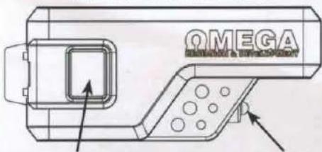
| FUNCTION | BUTTON(S) | NOTE |
 | CH3/AUX1 - Write function in first column* | |
 | CH4/AUX2 - Write function in first column* | |
 | CH5/AUX3 - Write function in first column* | |
 | AUX4 - Write function in first column* |
*These special functions may not be available on your vehicle. Consult your installer.
PROGRAMMING REMOTES TO THE SYSTEM (UP TO 4)
BEFORE YOU BEGIN: Have all remotes for the system at hand.
1) Turn the ignition key "ON" (do not start).
2) Press the valet button 5 times within 5 seconds of step 1.
- The horn will briefly sound
3) Press & release the "lock" button on each transmitter one after the other.
- 1-button models, press the "start" button.
- The siren/horn will chirp once for each transmitter.
- NOTE: When the first remote is learned all previous remotes are erased.
- NOTE: All other button functions will automatically be assigned.
4) Turn the ignition key "OFF".
- NOTE: The system will exit at any time after 10 seconds of no activity.
SCAN TO WATCH
HOW-TO VIDEO

4 Button / 1 Way Remote Start Systems
| CHIRPS/FLASHES | VIOLATED ZONE |
| LED ON | System in Valet mode |
| 1 | Hood opened |
| 2 | Brake pedal pressed |
| 3 | Bad tach signal or engine over-rev. |
| 4 | BLACK/WHITE wire lost ground |
| 5 | 3D motion detected while cranking |
| 6 | Received engine stop command |
| 7 | Alarm was triggered |
| 8 | Run time expired |
| 9 | Low vehicle battery voltage detected |
If the system fails to remote start or remote start stops unexpectedly, it will give a long horn/siren chirp followed by a series of short horn/siren chirps & light flashes. The short chirps/light flashes indicate the cause of the failure.
TIP: If remote start won't activate, the system may be in valet mode (Status LED ON). Press the valet button once to exit.
EXCALIBUR REMOTE START & SECURITY PERFECTED
4 Button / 1 Way Remote Start Systems
Visit www.CarAlarm.com today
To Download your complete operation guide and learn more about:
Additional Features
- Anti-Carjacking Mode - Customizing System Options
- Secure Code Override - Passive Security Functions
- Turbo Timer Support & Operation - Emergency Override
System Upgrades
-Linkr Smartphone Control
-2-Way Controllers w/ Extended Range
- Upgrading To Full Security With Sensors & Siren
Problems? Questions? Contact Customer Service:
800-554-4053 (toll free) | +1-770-942-9876 (outside USA)

Scan to register & download the full operation guide at CarAlarm.com!

Your System Model:
(Installer, write system model above)
This device complies with FCC Rules part 15. Operation is subject to the following two conditions: 1) This device may not cause harmful interference &, 2) This device must accept any interference that may be received, including interference that may cause undesired operation.
The manufacturer is not responsible for any radio or TV interference caused by unauthorized modifications to this equipment. Such modifications could void the user's authority to operate the equipment.
EXCALIBUR REMOTE START & SECURITY PERFECTED
RS-X70 QUICK REFERENCE
PROGRAMMING GUIDE (FOR FIRMWARE v1.6)
visit www.OmegaWeblink.com to get the latest firmware visit www.OmegaDealer.com to download a complete guide
Scan To Download the full installation guide from OmegaDealer.com! (login required)
Perform Vehicle Learn (US parson #10.151.269)
Vehicle Learn is the ultimate time sever and remote start configuration tool. It configures most
International features to match vehicle requirements.
Vehicle Learn Will:
• Automatically configure IGNITION, ACCESSORY AND START circuits to match the vehicle.
• Let you quickly choose crank delay (NOTE: wait-to-call its calls is always hooped;
• Simple bank interest bank averaging (50% rates only)
• A-to-date data and analytics
• Let you quickly enable menus. Intermission reservation mode.
Before You Begin:
• Can't use any mechanical pressure, 15 mm call joints.
- Set the parking brake. It is corrected to the BLACKWHITE who for manual transmission.
Vehicle Learn Procedure:
-
Turn the ignition key ON (co not start)
-
Press the valet button 3 times in less than 5 seconds.
- The system wall chip & dust lights to make a crank mouse [default: 1 inch/mm = 1.0 seconds]
-
(OPTIONAL) Press Valet 15 change dark delay
-
Start the engine with the key and let the engine search a norm
-
AUTOMATIC TRANSMISSION: Turn the ignition OFF.
- The system and chip & heat the lights sequind the of IGEACOSTART circular detected (place 4).
THE 1950-2000 European Conventionist and Europe for cooperation, other connections and in Japan
The following section, released the parking brake (3.5 cm³/min), is a 120-160 inch,
TIP. If you receive fewer which functions than clients you connected, check connections and try again.
Set the parking brake again to enter Manual Trans. Reservation Mode option selection ( installed feature #1).
- The system and given 8 that the rights to various current setting (instead: Z = EFR).
Ko#k##n a zat n## p###ing ##a## to me ##m##t## ##ing ###.
- 2014, 30: 19: 17: 16: 15: 14: 13: 12: 11: 10: 9: 8: 7: 6: 5: 4: 3: 2: 1: 0
Before turning the key OFF, perform the selected MT reservation sequence (see operation guide).
- When successful, the LED will once every 2 seconds (ALARM MODELS will finish twice every 2 seconds)
-
PUSH-BUTTON-START VEHICLES: Exit the vehicle & take the OEM for key 20 ft. away to allow remote start
-
Activate remote start within 50 seconds of Step 5. Wall until the engine is running and the LED flashes slowly
The system will turn direct data protocols and the other candidate engine protection, member facilitator, etc., by:
- "This drive should be issued, but this LED and/or dry, so that it never said you must repeat for 8. TO SAVE SETTINGS A COMPLETE VEHICLE LEAFIN: Pass the BRAKE pedal (the motor ask stop
This describes VEHICLE LEARN for example space. Even on installed feature #2 in bank 101
TO CANCELSTART OVER: Press & release the valet button once
Programming Features Manually
- Turn the ignition key "ON", then "OFF".
Press the valve button equal to the desired lock (press 2c for Back 2, w/c.)
- This must be done within 5 seconds at Sep. 1
- The financial crisis and the status of firm with cash maturing a specific bank (see bank machine).
NOTE: 105 claims; more from calls to call. 106 must start over to charge bonds.
NOTE: When following a break to 10 minutes, you will call for giving all other products your best care. Continue pressure 5-10 without delay. You will hear a 2nd knap chim after '10 pressure
Press the valet button equal to the desired feature's number
The sirenthem will chip equal to the selected feature.
- Finish presses before hearing any chips. EXAMPLE: press the value 5x, then you'll hear 5 chips.
Press the transmitter Button for travel soda, to select the inside slot, 4-SUPTON MODEL. Change the fan as by opening the transmitter built
equal to the desired setting. Complete all presses before bearing any claims.
- The sirenthom will chip equal to the selected setting.
- Repeat steps 3 & 4 at this time if you wish to change additional features
Turn the ignition key "ON" then "OFF" in each programming
NOTE: The system will sell substantially at any time after 10 seconds of no activity.
Scan To Download the full installation guide from OmegaDealer.com! (login required)
Features Banks
BANK 2 - Low Temp Auto Start: ignition on, off, press valid 2 times (3 chips / 3 LED flashes)
| ● Feature Color 1x Color 2x Color 3x | |||||
| T - Low Temp-Acc-Color Insured D-Cap | 15 Cmp | 1 |
BANK 3 - High Temp Auto Start: Ignition on. of, press variet 3 times (4 chips / 4 LED flashes)
| # Furniture Value 1x Value 2x Value 3x Value 4x | |||||
| 1 High Temp Auto Slot Introduction (Chang F DC Cap) | 75.0kg |
| BANK 5 - User Features: Ignition on all, press valid 6 times (Long chip/Fast LED flash) | ||||||
| # Feature | Lock Button(Replace #) | Unlock Button(Replace #) | Frame Button(Replace #) | Start Button(Replace #) | Lock + Unlock(Replace #) | Trunk + Short(Replace #) |
| 1. Remote Start Run Time | 3 min | 4 min | Green | 20 min | 30 min | |
| 2. Pending Light Check Insecure | Unlock Off, BL, On | Unlock Off, BL, Flush | Unlock Flats BL, On | Unlock Flats BL, Flush | ||
| 3. Check Insecure On Make Ander | Less | Meat Love | Meat High | High | ||
| 4. OPEN/WM Write Shock Form | Push to OFF | Push NED | Push Hi | Brady Snor | Prurred Print | |
| 5. Open Touch Unlock | Off | Off On - Lock | Up, Off - Unlock | Look On Unlock | ||
| 6. Door Open Upscale For Push Off | Off | Off | ||||
| 7. Unlock On To Make Up Now | On | Off | ||||
| 8. RF Activation Frequency | Start 1 | Start 2 | Start 3 | Start 4 | Start > New | Start > New |
| 9. Last Seen Arming | Off | Drive Back | On a Look | |||
| 10. Automatic Resetting | Off | Drive Lock | On a Look | Enhanced | ||
| 11. Connection Links | Show - From | Show Only | Show Dry | On Drawd | Off | |
| 12. Anti- \% Reporting | Gender | Door | Ignition - Door | Off | ||
| 13. Divide Cycles | See operation guide for programming instruction, DEFAULT LED | |||||
| 14. Inside Orations | On | Off | ||||
| 15. Active Trigger Detection | 30 sec | 40 sec | 30 sec | 120 sec | ||
| 16. Awning Entry | 1 sec | 10 sec | 10 sec | 40 sec | ||
| 17. Close Case When Using After | On | Off | ||||
| BANK 10 - Installer Features: Ignition on off, press valid over 10 times (2nd Long chirpfast LiD Facility) | ||||||
| 1. Box Advection (WHITEBLUE INC.) | 1 Phone | 2 Calendar | 3 Weeks | 4 Weeks | ||
| 2. Airline Sensor | Enrolled | Enloaded | ||||
| 3. Ling and Broadon | Port Voltage | Voltage | Twin Wave | Eraclab | Chips City | |
| 4. Court Delay (Offshore) | 1.5 sec | 16 sec | 22 sec | 80 sec | ||
| 5. Box R8 Port SWEEL Wks | Cone Light | Salt | Ignition | Accuracy | Status | Light Flight |
| 6. Box R8 Port BLUE Wks | light | Steps | 0.8 sec Digital Power | 40 sec Digital Power | Pulse After Exercise Of | Pictin |
| 7. Chips, Tires, Tires and Creek Only | 10 sec | 1 sec | 12 sec | 27 sec | Time | Average |
| 8. Tires and Lock Outputs | 1 sec | One | One second | One Change | ||
| 9. Tires and Lock Control | Off | Lock the Seat | One second to Steel | Lock a switch | Lock the 98 Off | |
| 10. Tires Time | Off | 1 min | 2 min | 3 min | ||
| 11. Motor Parts, Rosaline | On, Empty Off water | Off | On, Empty Off Water inside (present) | On, Empty Off Water inside (present) | ||
| 12. Cable Port Protocol | Sweer Off lines Out | Power On line, One | One Off lines | One Off lines | ||
| 13. Audio Paradox | On | Off | Off Line Only | One Second | ||
| 14. Power Pump - Air, Air, Air, Air | On | Off | ||||
| 15. Lock On Proven | On | Off | ||||
| 16. Banner Bracket | 4am Only | Amplified Grey | Amplified Grey | Automatic | ||
| 17. Low Tang Cell Balance | 9 sec | 220 sec | 300 sec | 420 sec | ||
| 18. OESI Arm/Chamber or Ctrl Air | Am/Cham | Am/CHG | CH, CH/Cham | CH, CH/CH | CH-Liquid Deams | CH-Liquid Ctrl Pulse |
| 19. ERIZON Wire | 4min | gasket | Trunk Relics | Plus After Reset | ||
| 20. Line Carrier Tube | Off | Off | ||||
| FEATURE SETTING KEY: | Default Setting | Installer Feature 13 (Alarm Functions) must be ON |
| * Door alarm received from lower level before read in or DATA server as starting results | ||
TIP: You can program features via your computer with Omega Weblink. Visit www.OmegaWeblink.com to learn more.
Features Reset
-
Enter Bank 10 feature programming (installer features - DO NOT SELECT ANY FEATURES)
-
Press LOCK + UNLOCK (or BRAKE x 6)
- 1-button/2-button models: Press the START button 5 times
- You will bear a long siren chip to indicate reset & exit programming.
Tach Wire Signal Learn
When utilizing the tech signal for engine detection, the vehicle's tech signal must be learned. Tech signals is learned during Vehicle Learn and usually does not have to be learned. Using either method below will automatically charge installer Feature #3 to Tech Wine. It is said tech signal is not detected, the system will not switch to Tech Wine mode. METHOD 1:
-
Turn the ignition key 'ON'
-
Prizes the broke pedal 5 times within 5 seconds in step 1. The step here is a key
-
Start the online
• The light LED
- Press the vault button to resemble the top signell if needed. If the engine has a high kick at start or allow the kick to
- The status light will flash off then back or when the signal has been resampled.
- Turn the ignition key 'OFF
METHOD 2:
-
Start the engine with the ignition say
-
Price & hold the strike price.
-
Price & hold the value
-
Press & Release the Wall Buttons
- The structure will store Slums
- The shots LED will run on when it has earned the tech signs. I'll check back wire & to again
- Turn the ignition key "OFF" or release the brake pedal to exit.
Programming Transmitters
Standard Programming: Use this method to program additional or replacement transmitters.
BEFORE YOU BEGIN: Have all transmitters which are to operate the system at hand.
-
Turn the ignition key "ON" (do not start).
-
Press the Vialt Button 5 times within 5 seconds of Sep 1
-
Press & release the "lock" button on each transmitter one after the other.
- 1-tuition models press the 'zist' button.
- The circadian will chip orcs for some insensible.
- NOTE: When the first new automobile is leased all cars only (carriers are nonused)
- NO: E; All other button functions will automatically be assigned.
- Turn the ignition key "OFF"
-100%: The share of non-controlling interests is 100% and the share of the company.
Alarm Diagnostics
Alarm Quick Test Mode: Use this mode to test all zones of the alarm system and quickly adjust any errors.
-
Press & hold the valve button
-
Press the Look button on the remote within 2 seconds of step (before the system enters valid mode)
The LED will begin to flash rapidly.
- Release the valet button
- The S&P 500 market index trading and zone divisions. See the lack of law
NOTE: CRPS will repeat every 2 seconds while the trigger remains disused.
NOTE: Multiple zones are digested for chips with cycle and the zone every 2 seconds then repress.
-
- Press Lock or Unlock on the controller or power cycle the system to salt.
- NO.1: There is no equal order to the results. On the 20th anniversary of the 20th quarter of the period is based.
Zone Violation Recall: To diagnose alarm triggers, alarm reaches the alarm with the remote and the status LED with flash to indicate which zone(s) were logged last. Turn the ignition key "UN" to clear alarm trigger memory.
| LED Flashes/Chips | Alarm Quick Test | Zone Violation Recall |
| 1 | Sensor Full Trigger | - |
| 2 | Hood | Hood |
| 3 | Door | Door |
| 4 | Sensor Warning | Sensor Full Trigger |
Remote Start Diagnostics
If remote start fails to activate, the system will chirp, flash the lights, and flash the status LED to indicate the
cause. If remote start, shifts down primarily after successfully starting, you can recall the violation by putting the system in valel mode (hold the valet button for 3+ seconds). Before the status LED turns on (system in valel mode), the LED will fetch to indicate any violated zones.
| LED Flashes | Violated Zone |
| 1 | Heat |
| 2 | Drake |
| 3 | Red bech original or engine covers |
| 4 | BLACKWITTE wire test ground |
| 5 | 3D sensors detected vehicle motion of the coming |
| 6 | Reiterated engine stop command (remote, telemodics, etc.) |
| 7 | Automotive logged |
| 8 | Run time expired |
| 9 | Low while battery voltage detected |
Copyright 2019 Omega Research & Development Technologies, Inc.
QIM RS-370 2019C65
RS-X70 Wire Diagram
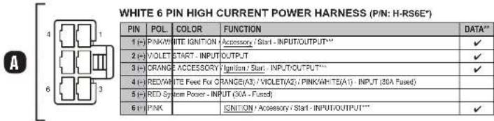
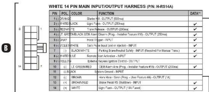


* Optional 'OL-HRN-RS' T-harnesses available.
Optional low current (LC) harness available - P/N H-RS6BLC (ask about HC>LC exchange program)
* √ = The function is supported via the data ports. Confirm vehicle support in interface module install guide.
Function auto-detected during VEHICLE LEARN procedure - SEE OTHER SIDE OF THIS SHEET
Default function is capitalized and underlined
TEMPERATURE SENSOR - DO NOT COVER
(For high/low temp auto start and for automatic low temp crank extender)
F ANTENNA / STATUS LIGHT / VALET PORT - Supports any compatible plug-in antennas or push-button status light (P/N: AU-LED-PB2)
GREEN & BLACK DATA PORTS - For Telematics / Data Sensor (Shock, Tilt, etc) / Vehicle Interface Module. (DBI & iDatalink protocols supported on both ports - see 'Vehicle Learn' or installer feature #12)
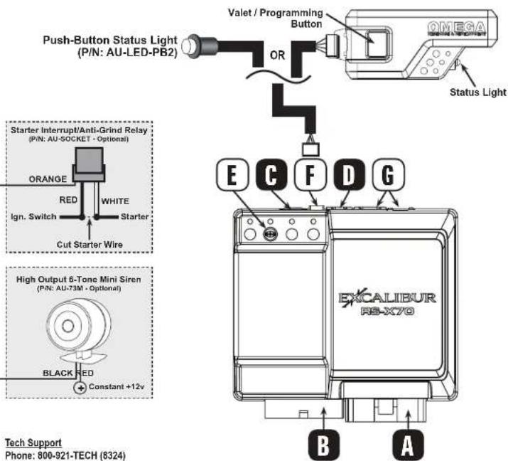
Tech Support
Phone: 800-921-TECH (8324)
Web: OmegaDealer.com
FB dealer group: Facebook.com/groups/omegadealer
Corporate Site / Product Info: CarAlarm.com
Introducing VIRTUAL SALESMAN, the industry's most sophisticated remote start & security system builder.
- He'll only offer your customers the products you carry.
- Intelligent installation quotes based on labor rates and install times set by you.
- He'll upsell every customer with the features & accessories you choose.
- He has a Built-in vehicle lookup that automatically selects the correct interface module.
- Choose which systems are offered per vehicle & fine tune labor with custom vehicle profiles.
- Get our interactive display or use him on any web enabled device. Even link to him from your website.
Virtual Salesman is just 1 of the benefits from the dealer portal at www.OmegaDealer.com.
only from
800.554.4053
sales@caralarm.com
ΩMEGA
RESEARCH & DEVELOPMENT TECHNOLOGIES, INC.

LAEVS370
YOUR SHOP NAME
REMOTE START & SECURITY SYSTEM DESIGNER
Ready To Combat Weather? Ready To Combat Theft?
Press the button below to use the industry's best remote start & security system designer.
PRESS HERE TO START

1 YEAR FREE!
LEAT STITCH
LASER ENGRAVED LOGOS
Copyright © 2015 Omega Research & Development Technologies, Inc.
CarAlarm.com | 800-554-4053
OMEGA
Get your very own Virtual Salesman at www.OmegaDealer.com
WARNING: THIS REMOTE
START IS ALSO AN ALARM!
ALARM EQUIPPED
Every Excalibur Remote Start Includes a Full Security Suite That Can Be Easily Enhanced
- Add any siren you like.
Siren, horn honk & parking light outputs
Take advantage of the full suite of INCLUDED security features! Every remote start can be a "combo"!
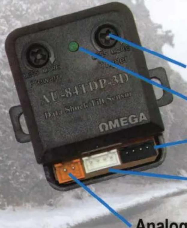
Add the AU-84TDP-3D to gain shock & tilt functions!
Sensor Adjustments
Trigger Indicator
Connect To The Starter's Data Port
Pass-Through Data Port For Other Accessories
Analog Door Trigger Inputs For RS models
(If door status is not available from the interface module)
The AU-84TDP-3D data shock & 3D tilt sensor works with any 70 series remote start.
- ADD FULL SECURITY IN A FEW MINUTES
- 3D MOTION SENSOR FOR MANUAL TRANSMISSION SAFETY
- TILT DETECTION FOR WHEEL PROTECTION & ANTI-TOW
phone-800.554.4053|web-caralarm.com
Linkr
MOBILE
CONTROL.
TRACK.
ALERT.

natural_image
Front view of a black Audi A sports car (no visible text or symbols)
natural_image
Side view of a black and green off-road vehicle with multiple wheels (no visible text or symbols)
natural_image
Illustration of a simple house with brown roof and green roof, no text or symbols presentAll Service Plans Include Full Functionality with GPS!
Control Multiple Devices
From One App
Controla Varios Dispositivos
Auto-track From Every
1 to 30 Days

ANDROID APP OR
Google play

Available on the
App Store
Download the FREE app!

Choose Custom Images &
Names For Each Device
Supports 6 Languages:
Apoya 6 Idiomas:
English
Español
Francais
Romana
Српки
Malay
Apple, the Apple logo, iPhone, and iPod
Touch are trademarks of Apple Inc., registered in the U.S. and other countries. App Store is a service mark of Apple Inc.
Google Play is a trademark of Google Inc.
POP-LINKR-84TDP3D-CARD
ΩMEGA
800-554-4053/770-942-9876
info@caralarm.com
www.caralarm.com
facebook.com/omegard
LAERSX70

- Table Of Contents
- Installation Considerations ...... 3
- Pin Main Wire Harness.... 3
- Pin Secondary Wire Harness....4
- Pin Secondary Wire Harness (cont'd) 8
- Green & Black Data Ports 8
- Pin Satellite Relay Port (RED) 9
- Pin Door Lock/Unlock Port (RED)....9
- Status Lights....9
- Valet / Programming Button 9
- Window Mount Antenna Module 10
- Tach Programming.... 11
- Programming Transmitters.... 11
- Programming Features 11
- BEFORE STARTING THE INSTALLATION, READ THIS ENTIRE MANUAL TO DETERMINE INSTALLATION REQUIREMENTS
- Pin Main Wire Harness
- RED & RED/WHITE WIRES - CONSTANT POWER (+) INPUT
- PINK WIRE - IGNITION/ACC/START (+) INPUT/OUTPUT
- Pin Main Wire Harness (cont'd)
- ORANGE WIRE - ACCESSORY/IGN/START (+) IN/OUT
- VIOLET WIRE - START (+) INPUT/OUTPUT
- PINK/WHITE WIRE - IGNITION/ACC/START (+) IN/OUT
- Pin Secondary Wire Harness
- ORANGE WIRE - STATUS/ANTI-GRIND (-) OUTPUT
- BROWN/RED WIRE - BRAKE PEDAL (+) INPUT
- BLACK/WHITE WIRE - NEUTRAL SAFETY (-) INPUT
- VIOLET/WHITE WIRE - TACH SIGNAL INPUT
- BROWN WIRE - HORN (-) OUTPUT
- WHITE WIRE - FLASHING LIGHT (+) OUTPUT
- WHITE/BLACK WIRE - FLASHING LIGHT (-) OUTPUT
- GRAY WIRE - HOOD TRIGGER (-) INPUT
- WIRE LEGEND
- NOTES
- VEHICLE LEARN PROCEDURE
- Pin Secondary Wire Harness (cont'd)
- YELLOW - ALARM IGNITION CONTROL (+) OUTPUT
- WHITE/BLUE WIRE - REMOTE START ACTIVATION (-) INPUT
- GREEN/RED WIRE - OEM ALARM ARM (-) OUTPUT
- GREEN/BLACK WIRE - OEM ALARM DISARM (-) OUTPUT
- RED/WHITE WIRE - TRUNK RELEASE / CH2 (-) OUTPUT
- Green & Black Data Ports
- GREEN WIRE - START (-) PROGRAMMABLE OUTPUT
- RED WIRE - CONSTANT (+) OUTPUT
- BLUE WIRE - STATUS (-) PROGRAMMABLE OUTPUT
- Pin Door Lock/Unlock Port (RED)
- GREEN WIRE - LOCK (-) OUTPUT
- Status Lights
- Valet / Programming Button
- Window Mount Antenna Module
- 3D Motion Sensor
- Vehicle Learn
- VEHICLE LEARN WILL:
- BEFORE YOU BEGIN:
- Tach Programming
- Programming Transmitters
- Programming Features
- RESTORING FEATURE SETTINGS TO FACTORY DEFAULT:
- EXCALIBUR REMOTE START & SECURITY PERFECTED
- THE CONTROLLER
- Transmitter battery replacement:
- Controller Functions
- Controller Functions (cont'd)
- AUXILIARY FUNCTIONS 1-4:
- ECHO 2-WAY READY
- LOW VOLTAGE & HIGH/LOW TEMP AUTOMATIC STARTING
- Programming The Activation Low Temperature Threshold:
- Programming The Activation High Temperature Threshold:
- Activation Using The Valet Switch
- Activation Using The Controller
- TURBO TIMER MODE
- PIT-STOP MODE
- XL PIT-STOP MODE
- MANUAL TRANSMISSION STARTING
- METHOD #1 - 3D MOTION SENSOR:
- METHOD #2 - RESERVATION MODE:
- Security System Features
- LAST DOOR ARMING
- AUTOMATIC REARMING
- PRE-WARN DETECTION
- Security System Features (cont'd)
- WHEN THE SYSTEM TRIGGERS
- Using The Valet Button
- EMERGENCY OVERRIDE
- SECURECODE
- VALET MODE
- The Status Light
- SECURITY SYSTEM STATUS
- AUTOMATIC TRANSMITTER VERIFICATION
- ALARM ZONE VIOLATION RECALL
- REMOTE START STATUS
- REMOTE START DIAGNOSTICS
- Anti-Carjacking Protection
- Programming Controllers/Transmitters
- User Programmable Features
- Feature #1 - Remote Start Run Time
- Feature #2 - Flashing Light Confirmations
- Feature #3 - Confirmation Chirp Volume
- Feature #4 - BROWN Wire Audible Output
- Feature #5 - Ignition Controlled Lock/Unlock
- Feature #6 - Open Door Bypass of Ignition Locking
- Feature #7 - Unlock w/ Trunk Release
- Feature #8 - Remote Start Activation From The Remote
- Feature #9 - Last Door Arming
- Feature #10 - Automatic Rearming
- Feature #11 - Confirmation Chirps
- Feature #12 - Anti-Carjacking
- User Programmable Features (cont'd)
- Feature #13 - SecureCode
- DEFAULT - 1 Press
- To custom program a new SecureCode:
- Feature #14 - Ignition Activated Override
- Feature #15 - Alarm Trigger Duration
- Feature #16 - Arming Delay
- Feature #17 - Open Door Warning Upon Arming
- Feature #1 - Remote Start Activation From The WHITE/BLUE Wire
- Feature #2 - Vehicle Learn
- Feature #3 - Engine Detection Method
- Feature #4 - Gasoline Or Diesel Engine
- Installer Programmable Features (cont'd)
- Feature #10 - Turbo Timer
- Feature #11 - Manual Transmission Reservation Mode
- Feature #12 Data Port Protocol
- Feature #13 - Alarm Functions
- Feature #14 - Pulse Ignition On Disarm
- Feature #15 Lock On Prewarn
- Feature #16 - Starter Interrupt Functions
- Feature #17 Low Temp Crank Extender
- Feature #18 - Arm, Disarm or Additional Channels
- Feature #19 - Horn Relay Function (3DB) / Brown Wire Function (non-3DB)
- Feature #20 Low Current / Motorcycle Mode
- Back Cover
- Color cover is in a separate file.
- Button / 1 Way Remote Start Systems
- Register today at www.CarAlarm.com
- MANUAL TRANSMISSION RESERVATION MODE
- PROGRAMMING REMOTES TO THE SYSTEM (UP TO 4)
- Visit www.CarAlarm.com today
- Additional Features
- System Upgrades
- Problems? Questions? Contact Customer Service:
- RS-X70 QUICK REFERENCE
- PROGRAMMING GUIDE (FOR FIRMWARE v1.6)
- Perform Vehicle Learn (US parson #10.151.269)
- Programming Features Manually
- Features Banks
- Features Reset
- Tach Wire Signal Learn
- Alarm Diagnostics
- RS-X70 Wire Diagram
- Ready To Combat Weather? Ready To Combat Theft?
- WARNING: THIS REMOTE
- START IS ALSO AN ALARM!
- ALARM EQUIPPED
- Linkr
- MOBILE
- CONTROL.
- TRACK.
- ALERT.
- All Service Plans Include Full Functionality with GPS!
Brand : OMEGA
Model : Excalibur RS-370
Category : Remote control