
KEW 1109S - Multimeter Kyoritsu - Free user manual and instructions
Find the device manual for free KEW 1109S Kyoritsu in PDF.


| Product Type | Digital Multimeter |
| Brand | Kyoritsu |
| Model | KEW 1109S |
| Dimensions (approx.) | 165 x 82 x 45 mm |
| Weight (approx.) | 350 g (including battery) |
| Power Supply | 9V battery (6F22) |
| Display | Digital LCD, 2000 counts |
| Auto-Ranging | Yes |
| DC Voltage Range | 200 mV to 600 V |
| AC Voltage Range | 200 V to 600 V |
| DC Current Range | 200 µA to 10 A |
| Resistance Range | 200 Ω to 20 MΩ |
| Continuity Test | Yes, with buzzer |
| Diode Test | Yes |
| Capacitance Measurement | 2 nF to 20 µF |
| Frequency Measurement | 2 kHz to 200 kHz |
| Temperature Measurement | Not specified (likely not included) |
| Data Hold | Yes |
| Backlight | Yes |
| Safety Rating | CAT III 600V |
| Accessories Included | Test leads, 9V battery, manual |
| Maintenance | Clean with dry cloth; avoid moisture and solvents |
| Spare Parts Availability | Test leads and battery from authorized dealers |
Frequently Asked Questions - KEW 1109S Kyoritsu
User questions about KEW 1109S Kyoritsu
0 question about this device. Answer the ones you know or ask your own.
Ask a new question about this device
Download the instructions for your Multimeter in PDF format for free! Find your manual KEW 1109S - Kyoritsu and take your electronic device back in hand. On this page are published all the documents necessary for the use of your device. KEW 1109S by Kyoritsu.
USER MANUAL KEW 1109S Kyoritsu
- Safety Warnings .... 1
- Understanding Some of the Basics in Electrical Testing Before Using the Multimeter 3
-
Features 5
-
Specifications 6
-
Instrument Layout 8
-
How to Read Scales ...... 9
-
Operating Instructions ...... 11
6-1 Preparation 11
6-2 DC Voltage Measurements 12
6-3 AC Voltage Measurements 13
6-4 Low Frequency (dB) Measurements 14
6-5 AC Output Voltage Measurements Using Output Terminal 15
6-6 DC Current Measurements 16
6-7 Resistance Measurements 17
6-8 Terminal Current LI, Terminal Voltage LV & Diode Test 20
6-9 Measuring I_CEO (leakage current of transistors) 22
6-10 Measuring h_FE (DC Current Amplification Factor) ..... 24
- Fuse & Battery Replacement 27
1. Safety Warnings
The instrument must be used by a competent, trained person and operated in strict accordance with the instructions. Kyoritsu Electrical Instruments Works, Ltd will not accept liability for any damage or injury caused by misuse or non-compliance with the instructions or safety procedures. It is essential to read and understand the safety rules contained in the instructions. They must be observed when using the instrument.
- This instruction manual contains warnings and safety rules which must be observed by the user to ensure safe operation of the instrument and retain it in safe condition for a long period. Therefore, read these operating instructions thoroughly and completely before using the instrument.
⚠ WARNING
This is a warning for the user to avoid electric shock hazard.
The symbol ⚠ on the instrument means that the user must read the instructions in this manual for safe operation of the instrument.
CAUTION
This is a caution for the user to avoid damage to the instrument.
⚠ WARNING
- Never open the back case during measurements.
- Never use the instrument to measure voltage higher than 250V on an industrial power line.
- When measuring a high voltage greater than 250V (in small power supply circuit and not on power transmission line), connect the test leads to the circuit under test after it is once de-energized. Do not touch the wiring or test leads by hand during voltage measurements. After the measurements, turn off power to the circuit under test and disconnect the test leads.
Never test a circuit voltage higher than 250V with the range selector switch erroneously set to one of the current or resistance range positions. The fuse may not protect the circuit.
- Never use the instrument in an explosive atmosphere especially when making current measurements.
CAUTION
- Before making measurements check that the range selector switch is at a proper range position. Make sure to remove the tips of the test leads from the circuit under test when changing the measuring range during measurements.
- Do not apply voltage to the current or resistance ranges. It may result in a fuse blow or instrument damage.
- Make certain to set the range selector switch to the OFF position after every use.
- It is recommended that the range selector switch should be set to the 250mA DC position to protect the instrument against the possible shock or vibration in transit.
Note: Take good care not to make voltage measurements with the range selector switch at the 250mA DC position. The fuse may blow or instrument get damaged.
- Do not expose the instrument to the direct sun, extreme temperature and humidity or dew fall for a long period. Also, care must be taken not to give a shock to the instrument by dropping or inadequate handling.
- Since the meter cover has been given an anti-static treatment do not rub it strongly with a dry cloth. Where anti-static charges are present on the meter window after it has been used for a long period of time, causing the meter pointer to deflect in an abnormal way, coat its surface with anti-static chemicals for plastics or wipe it with a dilute solution of anti-static fluid as a temporary measure.
- Understanding Some of the Basics in Electrical Testing Before Using the Multimeter
• Auxiliary Units (Prefixes)
There are a number of measurement units used for multimeters.
Volt (V), ampere (A) and ohm ( ) are most widely used as measurement units to indicate electrical potential, current and resistance. However, it is not always straightforward to handle these units as they sometimes too large or too small for practical use or calculation. Prefixes are therefore used as auxiliary units to simplify the usage of such measurement units.
The following table shows some of the examples:
| Auxiliary Unit | M km μn | P | ||||
| Read mega- | kilo- | milli- micro- | nano- | pico- | ||
| Multiply | 10^6 | 10^3 | 10^-3 | 10^-6 | 10^-9 | 10^-12 |
| Example | 2MΩII2000kΩ | 2kΩII2000Ω | 250mAII0.25A | 50μAII0.05mA | 200nFII0.2μF | 1000pFII0.001μF |
• Notes on Voltage & Current Measurements
It is important to understand the basic differences between current and voltage measurements for proper use of multimeters.
Voltage measurements are designed to detect potential difference between two points. Make certain that the multimeter is connected in parallel with the circuit under test.
Current measurements are intended to monitor the consumption of current in the circuit resulting from the application of voltage. Make sure to connect the multimeter in series with the circuit under test.
Generally speaking, the internal resistance of a voltmeter should preferably be larger, while that of an ammeter should be smaller. If the multimeter is erroneously connected in parallel with a circuit for current measurements, the likely result will be the flow of excessive current and subsequent damage to the fuses and other electronic components. To avoid such a potential danger it is necessary to have a good understanding of voltage and current measurements.
Voltage Measurements Current Measurements (Parallel Connection) (Series Connection)
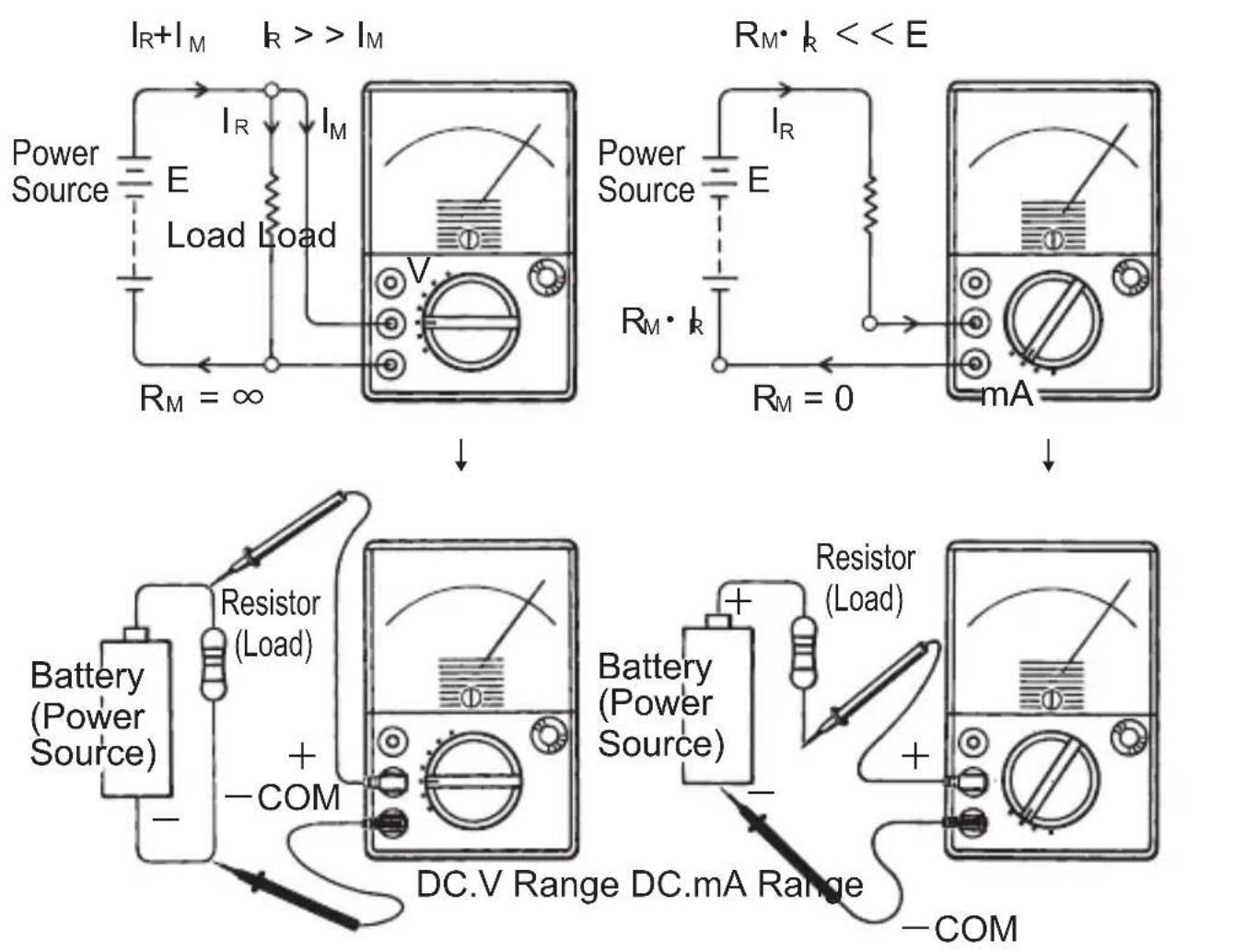
Measuring voltage at both ends of a resistor.
Measuring current being consumed by a resistor.
I_M ...... Meter Current
I_R ...... Load Current
E ...... Power Source Voltage
R_M ...... Internal Resistance of Multimeter
Fig. 1
2. Features
- Mirrored scale for easy and accurate reading.
- 19 measuring ranges for a wide scope of application.
- OUTPUT terminal to cut off the DC component of AC voltage being measured.
- h_FE scale for transistor checking.
- dB scale (-10 - +62dB).
-
Safety designed input terminals and test leads.
-
Specifications
| Functions Measuring Ranges Accuracy | ||
| DC Voltage(7 ranges) | 0-0.1 V0-0.5V0-2.5V0-10V (20kΩ/V)0-50V0-250V0-1000V | ±3% of full scale |
| 0-10V | ||
| AC Voltage(4 ranges) | 0-50V (9kΩ/V)0-250V0-1000V | ±3% of full scale |
| DC Current(4 ranges) | 0-50μA (terminal voltage approx. 100mV)0-2.5mA (terminal voltage approx. 100mV)0-25mA (terminal voltage approx. 150mV)0-250mA (terminal voltage approx. 550mV) | ±3% of full scale |
| Resistance(4 ranges) | 0-2kΩ (20Ω mid-scale)0-20kΩ (200Ω mid-scale)0-2MΩ (20kΩ mid-scale)0-20MΩ (200kΩ mid-scale) | ±3% of scale length |
| Current across Terminals at Resistance Range (LI)(4 ranges) | 0-150mA (x1 range)0-15mA (x10 range)0-150μA (x1k range) | ±5% of scale length(Battery voltage at 3V) |
| 0-60μA (x10k range) | (Battery voltage at 12V) | |
| Voltage across Terminals at Resistance Ranges (LV)(4 ranges) | 0-3V (x1 , x10, x1 k ranges) | ±5% of scale length(Battery voltage at 3V) |
| 0-12V (x10k) | (Battery voltage at 12 V) | |
| Low FrequencyOutput UsingOUTPUT Terminal | 0-10V0-50V0-250V0-1000V | Refer to frequencycharacteristic chart |
| Low FrequencyOutput (dB)(4 ranges) | 10V AC -10 - +22dB50V AC +4 - +36dB250V AC +18 - +50dB1000V AC +30 - +62dB(0 dB = 0.775V(1mW)across a 600Ω line) | Refer to frequencycharacteristic chart |
| DC Current AmplicationFactor ( h_FE ) (1 range) | h_FE : 0-1000 (atΩ× 10 range) | ±3% of scale length |
Dimensions: 100 (W) x 150 (L) x 47 (D)mm
Weight: Approx. 330g
Accessories: Test Leads (Model 7066A) - 1 set
F250V 0.5A fuse - 2 pcs. (including one spare fuse also installed into the housing case)
1.5V Battery Type R-6P, SUM-3, AA or equivalent - 2 pcs.
(Installed into the instrument)
9V Battery Type 6F22, 006P PP3, or equivalent
- 1 pce (installed into the instrument)
Instruction Manual - 1 copy
4. Instrument Layout

① Meter Pointer
③ OUTPUT Terminal
⑤ -COM (N) Terminal
⑦ Mirrored Scale Plate
⑨ Housing Case
⑪ Range Selector Switch
② Meter Zero Adjust Screw
④ +(P) Terminal
⑥ Front Panel
⑧ Meter Window
⑩ Ohm Zero Adjust Knob
- How to Read Scales
| Measuring Ranges | Scales | How to Read Scales | input Terminals | |
| DC Voltage (7 ranges) | 0.1V | B 10 | X0.01 | +&-COM |
| 0.5V | B50 | X0.01 | ||
| 2.5V | B 250 | X0.01 | ||
| 10V | B 10 | X1 | ||
| 50V | B50 | X1 | ||
| 250V | B250 | X1 | ||
| 1000V | B10 | X100 | ||
| AC Voltage (4 ranges) | 10V | C10 | X1 | +&-COM |
| 50V | B50 | X1 | ||
| 250V | B250 | X1 | ||
| 1000V | B10 | X100 | ||
| DC Current (4 ranges) | 50μA | B50 | X 1 | +&-COM |
| 2.5mA | B250 | X0.01 | ||
| 25mA | B250 | X0.1 | ||
| 250mA | B250 | X1 | ||
| Resistance (4 ranges) | X1Ω | A 0-2k | X1 | +&-COM |
| x10Ω | A0-2k | X10 | ||
| x1kΩ | A0-2k | X1k | ||
| X10kΩ | A0-2k | X10k | ||
| Current across Terminals (LI)(4 ranges) | X1Ω | E15 | X10(mA) | +&-COM |
| X10Ω | E15 | X1(mA) | ||
| X1kΩ | E15 | X 10(μA) | ||
| X10kΩ | E15 | X 4(μA) | ||
| Voltage across Terminals (LV)(4 ranges) | x1Ω | F3 | X1(V) | +&-COM |
| X10Ω | F3 | X1(V) | ||
| X1kΩ | F3 | X1(V) | ||
| X10kΩ | F3 | X4(V) | ||
| Low FrequencyOutput UsingOUTPUT Terminal(4 ranges) | 10V50V250V1000V | C10B 50B 250B10 | X1X1X1X1X 100 | Output &-COM |
| Low FrequencyOutput (dB)(4 ranges) | 10V50V250V1000V | G - 10-+22dBG - 10-+22dBG - 10-+22dBG - 10-+22dB | X1X1 + 14dBX1 + 28dBX1 + 40dB | + & -COM orOutput &-COM |
| DC CurrentAmplificationFactor ( h_FE )(4 ranges) | X10Ω D 0-1 | 000 X1 +& | -COM |

6. Operating Instructions
6-1. Preparation
- Make certain that the batteries are installed into the battery case with polarity in correct position. Also, make sure that the fuses are properly installed.
- The test leads are safety designed, but make sure that they are securely connected to the instrument before use.
- Check that the meter pointer lines up with the "0" mark on the left end of the scale. If it is off zero, rotate the zero adjust screw to bring the pointer to the zero position. Accurate measurements cannot be made without the zero adjustment.
- With the range selector switch at the x 1Ω range position and the test leads connected to the + and -COM terminals of the instrument, short the test leads together. If the pointer does not deflect at all, the probable cause is the absence of batteries or the blown fuse. [Refer to section 7]
- With the range selector switch set to the x1Ω range position, short the tips of the test leads together. Turn the ohm zero adjust knob and make certain that the meter pointer moves to the "0" mark on the right end of the ohm scale. If not, the battery voltage is insufficient. Replace all of the 1.5V batteries (R6P, SUM-3 or equivalent). Refer to section 7 for battery replacement.
- With the range selector switch at the x10kΩ position short the tips of the test leads together. Then, turn the zero adjust knob clock-wise and make certain that the meter pointer moves to the "0" mark on the right end of the ohm scale. If not, the battery voltage is insufficient. Replace the 9V battery (6F22, 006P or equivalent).
- Select a measuring range suitable for the circuit being tested. When in doubt as to the maximum voltage or current ^1 t expected, make sure to start with the highest voltage or current range of the instrument.
6-2. DC Voltage Measurements
⚠ WARNING
When measuring a high voltage greater than 250V, turn off power to the circuit under test 8.nd follow the steps as described below. Then, turn on power to the circuit being measured and proceed with the voltage measurements. Be careful not to touch the wiring, test leads and the instrument during voltage measurements. After making measurements, turn off power to the circuit under test and disconnect the test leads.
⚠ WARNING
Never use the instrument on a high voltage power line carrying more than 250V.
⚠ WARNING
Never make voltage measurements with the range selector switch set to the DC mA or ohm range position or the test lead erroneously connected to the AC 15A terminal. This may not only damage the instrument or blow the fuse, but also cause an injury to the operator.
Applications:
Measuring voltage on batteries, electrical appliances, bias voltage of IC of transistor circuits and any other DC voltages.
(1) Insert the red test lead into the + terminal of the instrument and the black test lead into the -COM Terminal.
(2) Set the range selector switch to the desired DC voltage range position.
(3) Connect the red test lead to the positive (+) side of the circuit under test and the black test lead to the negative (-) side of the circuit (in parallel with the circuit).
(4) If the measured voltage is less than 250V, set the range selector switch to the lower voltage range position for more accurate reading.
6-3. AC Voltage Measurements
⚠ WARNING
When measuring a high voltage greater than 250V, turn off power to the circuit under test and follow the steps (1) to (3) as outlined below. Then, turn off power to the circuit under test and proceed with the voltage measurements. Never touch the wiring, test leads and instrument during measurements. After the voltage measurements, make sure to turn off power to the circuit under test and disconnect the test leads.
⚠ WARNING
Never use the instrument on a high voltage power line carrying move than 250V.
WARNING
Never make voltage measurements with the range selector switch set to the DC mA or ohm range position. This may not only damage the instrument or blow the fuse, but also cause an injury to the operator.
Applications:
Measuring voltage on household and factory electrical installations especially those for lighting, commercial power lines, power supply circuits, taps of transformers, etc.
(1) Insert the red test lead into the positive (+) terminal of the instrument and the black test lead into the negative (-) COM terminal.
(2) Set the range selector switch to the desired AC voltage range position.
(3) Connect the test leads in parallel with the circuit under test (polarity of the circuit under test may be disregarded for AC voltage measurements).
(4) As described in section 6-2-(4) for DC voltage measurements, select the desired AC voltage range switch position.
6-4. Low Frequency Output (dB) Measurements
Applications:
Measuring the ratio of output to input for amplifiers, transmission circuits, etc.
The ratio of output to input in amplifier and transmission circuits is expressed in logarithmic values as the human sense of hearing responds to the level of sound logarithmically. This is measured in terms of decibels (dB). Where the load impedance of a circuit is constant two values of power can be compared simply by indicating input to output voltage (current) ratio in dB.
The dB readings on the scale are references to 0 (zero) dB power level of 0.001 watt (one milliwatt) across 600 ohms, or 0.775V AC across 600 ohms. therefore, output in a 600 ohms impedance circuit can be read directly from the dB scale. When the impedance of a measuring circuit is not 600 ohms, however, a dB reading obtained is simply the result of measuring an AC voltage on the corresponding dB scale.
(1) To measure decibels, read the dB scales in accordance with the instructions for AC voltage measurements.
(2) For the 10V AC range read the dB scale directly (0 dB=1mW or 0.775V across 600 ohms). For other ranges including the 50V range read the dB scale and add the appropriate number of the dB to the reading as shown on Table 2.
Table 1
| AC Volt Ranges | 10V 50V 250V | 1000V | ||
| Add dB 0 +1 | 4dB +28dB +40dB | |||
| Max. dB +22 | dB +36dB +50 | dB +62dB | ||
6-5. Low Frequency Output Measurements Using Output Terminal
⚠ WARNING
When measuring a high voltage greater than 250V, turn off power to the circuit under test once and then follow the steps (1) to (3) as described for AC voltage measurements. Then, turn on power to the circuit and proceed with Low Frequency Output measurements.
Never touch the wiring, test leads or the instrument during measurements. After taking measurements, turn off power to the circuit under test and disconnect the test leads.
⚠ WARNING
Never make Low Frequency Output measurements with the range selector switch set to the DC mA or ohm range position. This may result in instrument damage, fuse blow or a possible injury to the operator.
Note: The blocking capacitor connected in series with the OUTPUT terminal may change the AC voltage response at low frequencies. The lower the Low Frequency Output the more apparent the change. The AC voltage response also changes at higher frequencies due to the frequency characteristics.
Use Table 2 for frequency characteristics to correct the Low Frequency Output reading.
Applications:
Measuring output voltage of low frequency amplifiers.
Detecting horizontal signals in horizontal amplification circuits of TV sets.
Detecting the presence of input signals in synchronous isolation and amplification circuits of TV sets.
The 1109S has a capacitor in series with the OUTPUT terminal. This OUTPUT terminal is useful for measuring the AC component only of a DC coupled Low Frequency Output in TV sets, audio equipment circuits, etc. by blocking the DC component.
(1) Insert the red test lead into the OUTPUT terminal and the black test lead into the -COM terminal.
(2) Make Low Frequency Output measurements in accordance with the instructions given for AC voltage measurements.
Table 2 Frequency Characteristics

line
| Frequency [Hz] | 10V AC OUTPUT VOLTAGE RANGE (dB) | 50V AC OUTPUT VOLTAGE RANGE (dB) | 1000V AC OUTPUT VOLTAGE RANGE (dB) | | -------------- | ------------------------------- | ------------------------------- | --------------------------------- | | 30 | -2.5 | -2.5 | -2.5 | | 60 | -1.5 | -1.5 | -1.5 | | 100 | -0.5 | -0.5 | -0.5 | | 200 | 0.5 | 0.5 | 1.5 | | 5k | 1.5 | 1.5 | 2.5 | | 10k | 2.5 | 2.5 | 3.0 | | 20k | 3.0 | 3.0 | 3.5 | | 50k | 2.5 | 2.5 | 3.0 | | 100k | 2.0 | 2.0 | 2.5 |6-6. DC Current Measurements
WARNING
Make sure that the test leads are securely connected to the circuit. If the test prods are disconnected inadvertently, a high voltage may develop in the circuit.
WARNING
Never apply voltage to the current ranges. The fuse could blow or the instrument get damaged.
Especially when a voltage higher than 250V is applied accidentally, the fuse may not protect the circuit.
Applications:
Measuring currents in DC operated electrical appliances, bias current of transitors, IC's, etc.
(1) Insert the red test lead into the + termin\~1 and the black test lead into the -COM terminal.
(2) Set the range selector switch to the 250mA range position.
(3) Turn off power to the circuit under test.
(4) Connect the red test lead in series with the positive (+) side of the circuit under test and the black test lead with the negative (-) side.
(5) Turn on power to the circuit under test.
(6) When the reading is below 25mA, set the range selector switch to the lower range for more accurate reading and proceed with the measurement.
6-7. Resistance Measurements
⚠ WARNING
Be sure to turn off power to the circuit under test before making resistance measurements.
⚠ WARNING
Never apply voltage to the ohm ranges. The fuse could blow or the instrument get damaged. Especially when a voltage higher than 250V is applied, the fuse may not protect the circuit.
⚠️ CAUTION
A maximum voltage of 12V is present on the ×10kΩ range. It may damage IC's for low voltage equipment.
Before making resistance measurements, carefully check the withstand voltage of the circuit under test.
CAUTION
Make the zero ohm adjustment after every change of the measuring range to obtain a more accurate reading.
Application:
Checking a resistance value of resistors, circuit continuity, short and open circuits, etc.
(1) Insert the red test lead into the +terminal and the black test lead into the -COM terminal.
(2) Set the range selector switch to the desired range position.
(3) With the test lead tips shorted together turn the zero ohm adjust knob so that the meter pointer lines up with the zero mark at the right end of the ohm scale.
(4) Turn off power to the circuit under test.
(5) Connect the test leads to both ends of the circuit under test and take the reading (Fig. 2).

Fig. 2
Notes: Fig. 3 shows the resistance measuring circuit. The positive (+) polarity of the battery is connected to the positive (+) terminal of meter. Therefore, the polarity of the terminals is reversed for resistance measurements, with output voltage from the -COM terminal being positive (+) and output voltage from the +terminal negative (-). (Fig. 3).
A good knowledge of this relationship will be helpful in testing semi-conductors such as transistors and diodes as well as electrolytic capacitors.
Polarity of Multimeter Terminals at Resistance Measurements

Fig. 3
6-8. Terminal Current LI, Terminal Voltage LV & Diode Test
⚠️ CAUTION
Do not measure the internal resistance of a diode with low reverse withstand voltage using x 10kΩ range. The 12V voltage to be applied at this test could damage the diode. Check the rating of a diode before testing.
(1) Current flowing across the -COM terminal and + terminal during resistance measurements is indicated as LI. When LI flows into the circuit under test there occurs a voltage drop. This is defined as LV. Use the scale marked LI and LV for reading terminal current and voltage. Circuit impedance may change according to the current that flows into the circuit being measured or the voltage applied to the circuit. Also, an abnormal condition may develop in the circuit due to its self heating. Therefore, make resistance measurements at each range with the above in full consideration
Shown below are the values of terminal current and voltage on each resistance range: Table 3
| Resistance Range | X1 X10 | X1k X10k | ||
| Multiply by 10 | Direct Reading | 10 4 | ||
| Max. Terminal Current LI | 150mA 15 | mA 150μA 60μA | ||
| Max. Terminal Voltage LV | 3V 3V 3V | 12V |
(2) If the connection to the circuit is made as shown in Fig. 4, it is possible to measure the forward current IF or reverse current I_R of a diode using the LI scale. It is also possible to measure the forward voltage V_F or backward voltage V_A of a diode using the LV scale (Fig. 4).
(3) As described for the resistance measurements, make the ohm zero adjustment after every change of the measuring range.
(4) The meter pointer deflects close to full scale when the forward current I_F is measured. However, it hardly deflects when the reverse current I_R is measured.
The forward voltage of the average germanium diode measures 0.1 V to 0.2 V and that of the silicon diode 0.5 V to 0.8 V.
(5) Since the maximum open circuit voltage at the low resistance ranges is 3V (12V at X 10k range), it is possible to light up an LED having a forward voltage of more than 1.5V and measure forward current I_F as well. The reading on the LI scale indicates the forward current _F lat which the LED lights up. The reading on the LV scale also indicates the forward voltage V_F .
For testing a large LED use the X1 Ω range. For a smaller LED having less than 10mA IF use the X10Ωrange.

Fig.4
6-9. Measuring I_CEO (leakage current of transistors)
CAUTION
The leakage current does not change significantly according to voltage, but it rather exhibits constant current characteristics.
However, note that the leakage current is very sensitive to the temperature and varies with the temperatu re change (approximately twice as against 10^ C temperature rise)
CAUTION
When measuring I_CEO , do not touch the base of a transistor. Base current will flow and I_CEO increase.
CAUTION
If tested on the x10kΩ range, a transistor having V_CE less than 12V could possibly be damaged. Always check the rating of a transistor before testing.
(1) Use the resistance measuring ranges to test transistors.
(2) Insert the red and black test leads into the P(+) and N(-COM) terminals respectively.
(3) With the tips of the test leads shorted together, turn the ohm zero adjust knob so that the meter pointer lines up with the "0" mark on the right end of the ohm scale.
(4) Connect the test leads to the transistors according to their polarity, as shown in Fig. 5 A for the NPN transistor and Fig. 5 B for the PNP transistor.
(5) Fig. 5 may be represented by an electrical circuit (Fig. 6). (Part of the circuit located on the right side of the P/N terminals corresponds to be internal circuit of the multimeter.)
(6) Current flowing between the P and N terminal is a reverse leakage current I_CEO . Take the reading on the LI scale.
Measuring Leakage Current of Transistor I_CEO
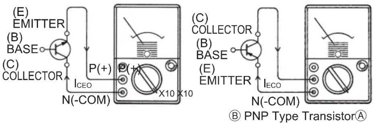
Fig. 5
(7) The leakage current of the silicon transistor is too small to give pointer deflection. If the pointer should deflect, the likely cause would be some fault of the silicon transistor.
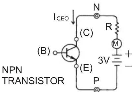
Fig. 6
(8) With the germanium transistor the leakage current flows even if it is good, but the amount slightly differs with the types of the transistor. Use Table 4 below to determine if the germanium transistors are good or bad.
| Table 4Leakage Current I_CEO ofGermanium Transistors | |
| Small &Medium Sized Transistors | Large SizedTransistors |
| Approx. 0.1 - 2mA Approx. 1 - 5mA | |
If the leakage current exceeds the above values appreciably, the transistors are faulty.
6-10. Measuring h_FE (DC Current Amplification Factor)
CAUTION:
With the germanium transistor, the leakage current flows into the collector side, causing that much error in leakage current measurements. Therefore, obtain a true value of leakage current by deducting a h_FE value equivalent to the leakage current from the measured value.
(1) The following will explain about the principle of h_PE measurements.
As shown in Fig. 7, the collector and emitter of a transistor are connected to the multimeter. When a resistor R of a certain resistance value (approx. 24kΩ) is connected across the N (-COM) terminal of the instrument and the base of the transistor, base-terminal current I_B , determined by R (approx. 24kΩ), flows and current I_C , multiplied by h_FE , also flows into the collector of the transistor, resulting in the increase of DC current and thus causing the meter indication to change notably.
Theoretically, the h_FE ( =I_C/I_B ) of a transistor (DC current amplification factor) can be measured by plotting the amount of the current change on a separate h_FE scale.
The h_E scale for KEW1109S is marked for the 24kΩ R (approx. 100μA base current at 3V LV).
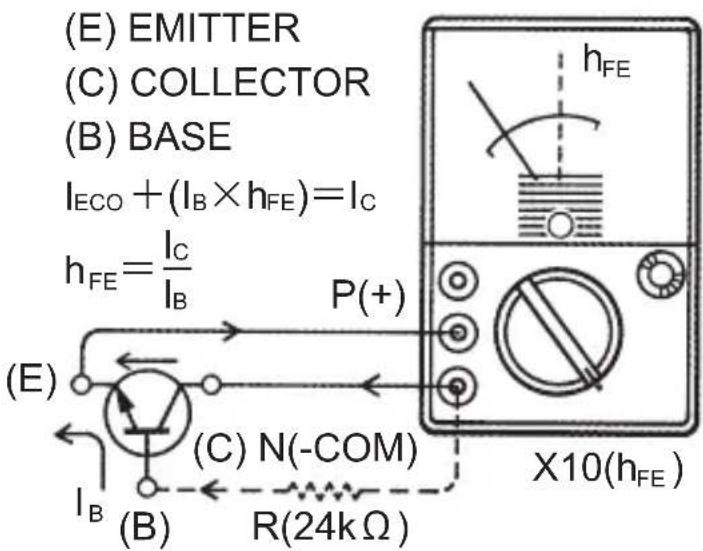
Fig. 7
(2) How to Use h_FE Test Leads
The test lead set mainly consisting of a resistor and a clip as shown in Fig. 8 is on the market and is recommended for use in making h FE measurements.
Test Lead Set for h_FE Measurements

Fig. 8

Fig. 9
As indicated in Fig. 9, connect the _FE h test lead (1) to the multimeter, according to the polarity of a transistor to be tested; N (-COM) terminal for the NPN type transistor or P (+) terminal for the PNP type transistor.
Also, connect the h_FE test lead (2) to the P(+) terminal for the NPN type transistor and the N (-COM) terminal for the PNP type transistor. With the test lead clips (E) and (C) shorted, turn the ohm zero adjust knob so that the pointer lines up with the zero (0) mark on the right end of the ohm scale. Then, connect the h_FE test lead clips as follows:
Clip (C) and clip (B) for h_FE test lead (1) to the collector and base terminals of the transistor respectively.
Clip (E) of the h_FE test lead (2) to the emitter of the transistor.
(3) When the transistor is good, the indicate d value is small, representing leakage current I_CEO only with the base terminal open ( I_B=0 ).
If base-terminal DC current B Iflows, collector-terminal DC current C I changes and meter gives a reading of the current increased by I_B X h_FE .
(4) When the transistor is faulty, the three possible cases may be considered.
There is no change in the current reading between the times when the base terminal is open ( I_B=0 ) and when I_B flows.
No meter pointer deflection even when I_B flows.
The meter pointer moves past the h_FE scale and deflects close to full scale, even when the base terminal is open ( I_B=0 ).
7. Fuse & Battery Replacement
WARNING
Never replace the fuse or batteries during measurements. Make sure to set the range selector switch to OFF position and remove the test leads from the instrument before replacing the fuse and batteries.
Always use the F 2S0V 0.5A fuse as specified.
(1) When the fuse blows remove the housing case by unscrewing the case fixing screw to replace the fuse.
(2) When 2 x1.5V battery (R-6P, SUM-3 or equivalent) are exhausted, it is no longer possible to zero ohm adjust on the x 1Ω range. Remove the housing case by unscrewing the case fixing screw to replace the batteries. Observe correct polarity when replacing the batteries.
(3) When the 9V battery (6F22, 006P or equivalanet) is exhausted, it is no longer possible to zero ohm adjust on the X10kΩ range. Remove the housing case by unscrewing the case fixing screw to replace the battery.

PCB Component Layout Drawing

Fig. 11
PARTS LIST
| No. | DESCRIPTION |
| R1 Resistor 1/2WF, ( 15MΩ) DC 1000 V | |
| R2 Resistor 1/4WF, ( 4MΩ) DC 250 V | |
| R3 Resistor 1/4WF, ( 800 KΩ) DC 50 V | |
| R4 Resistor 1/4WF, ( 150 KΩ) DC 10 V | |
| R5 Resistor 1/4WF, ( 40KΩ) DC 2.5 V | |
| R6 Resistor 1/2WF, ( 8KΩ) DC 0.5 V | |
| R7 Resistor 1/2WF, ( 83.3 KΩ) AC 10 V | |
| R8 Resistor 1/4WF, ( 360 KΩ) AC 50 V | |
| R9 Resistor 1/4WF, ( 1.8MΩ) AC 250 V | |
| R10 Resistor 1/2WF, ( 6.75MΩ) AC 1000 V | |
| R11 | Resistor 1/4WF, ( 40.7 Ω) DC 2.5mA |
| R12 Resistor 1/4WF, ( 4 Ω) DC 25mA | |
| R13 Resistor 1/2WF, ( 0.379 Ω) DC 250mA | |
| R14 Resistor 1/2WF, ( 18 Ω) ΩX 1 | |
| R15 Resistor 1/4WF, ( 200 Ω) ΩX 10 | |
| R16 Resistor 1/4WF, ( 34KΩ) ΩX 1K | |
| R18 Resistor 1/4WF, ( 240 Ω) | |
| R19 Resistor 1/4WF, ( 44KΩ) | |
| R20 Resistor 1/4WF, ( 195 KΩ) ΩX10K | |
| R21 Resistor 1/4WF, ( 18KΩ) | |
| R22 Resistor 1/4WF, ( 750 Ω) | |
| R23 Resistor 1/4WF, ( 31KΩ) | |
| VR1 Variable Resistor, ( 10KΩ) | |
| D1,2,3 | Diode 1N4448 |
| C1 Ceramic Capacitor, | 0.047μF50V |
| C2 Metal Film Capacitor, | 0.047μF630V(OUTPUT) |
| BT1 Battery | 1.5V,R6P,SUM-3 or equiv. (X2) |
| BT2 Battery | 9V, 6F22, 006P or equiv. |
| F1 | Fuse, Fast Acting Type, F250V/0.5A, φ6×30mm |
| M | Meter Movement, (44μA / 1.25KΩ) |
| BS1 | Battery Contacts (X4) |
| BS2 | Battery Contact (X1) |

CIRCUIT DIAGRAM
MEMO
MEMO
DISTRIBUTOR
Kyoritsu reserves the rights to change specifications or designs described in this manual without notice and without obligations.

natural_image
Abstract black arrow symbol pointing left, enclosed in a rounded rectangle (no text or numbers)Factory: Ehime, Japan
- Safety Warnings
- ⚠ WARNING
- CAUTION
- • Auxiliary Units (Prefixes)
- • Notes on Voltage & Current Measurements
- Features
- Instrument Layout
- Operating Instructions
- 6-1. Preparation
- 6-2. DC Voltage Measurements
- Applications:
- 6-3. AC Voltage Measurements
- WARNING
- 6-4. Low Frequency Output (dB) Measurements
- 6-5. Low Frequency Output Measurements Using Output Terminal
- Use Table 2 for frequency characteristics to correct the Low Frequency Output reading.
- 6-6. DC Current Measurements
- 6-7. Resistance Measurements
- ⚠️ CAUTION
- Application:
- 6-8. Terminal Current LI, Terminal Voltage LV & Diode Test
- 6-9. Measuring I_CEO (leakage current of transistors)
- 6-10. Measuring h_FE (DC Current Amplification Factor)
- CAUTION:
- Fuse & Battery Replacement
Brand : Kyoritsu
Model : KEW 1109S
Category : Multimeter