
KEW 2062BT - Multimeter Kyoritsu - Free user manual and instructions
Find the device manual for free KEW 2062BT Kyoritsu in PDF.


| Product Type | Clamp Power Meter (Multimeter) |
| Dimensions | 247 × 105 × 49 mm |
| Weight | Approx. 490 g (including batteries) |
| Power Supply | 2 × AA alkaline batteries (LR6) |
| Battery Life | Approx. 58 hours (W function, continuous, backlight off) |
| Display | Field effect LCD with backlight, 4-digit |
| Measurement Functions | AC voltage, AC current, power (active/reactive/apparent), power factor, frequency, harmonics (1st–30th), phase detection |
| AC Voltage Range | 30.0 V to 1100 V RMS |
| AC Current Range | 0.60 A to 999.9 A RMS (auto-ranging) |
| Power Range | 0.00 kW to 1210 kW |
| Harmonics Analysis | 1st to 30th order, THD-F and THD-R |
| Phase Detection | Positive/negative sequence, missing phase detection |
| Bluetooth | Bluetooth Ver5.0 (KEW 2062BT only), app “KEW Power*” for remote monitoring |
| Max Conductor Diameter | 55 mm |
| Safety Rating | CAT IV 300 V, CAT III 600 V, CAT II 1000 V |
| Standards | IEC 61010-1, IEC 61326 Class B, IP40 |
| Accessories Included | Test leads MODEL7290 (red, black, yellow) with alligator clips, soft case MODEL9198, batteries, manual |
| Maintenance | Clean with damp cloth and neutral detergent; do not use abrasives |
| Repairability | Return to local Kyoritsu distributor for repair; no user-serviceable parts |
Frequently Asked Questions - KEW 2062BT Kyoritsu
User questions about KEW 2062BT Kyoritsu
0 question about this device. Answer the ones you know or ask your own.
Ask a new question about this device
Download the instructions for your Multimeter in PDF format for free! Find your manual KEW 2062BT - Kyoritsu and take your electronic device back in hand. On this page are published all the documents necessary for the use of your device. KEW 2062BT by Kyoritsu.
USER MANUAL KEW 2062BT Kyoritsu
Safety precautions....3
Chapter 1 Functional overview ....7
Chapter 2 KEW 2062/2062BT features....8
Chapter 3 Basic operation ...... 9
3.1 Function switch....9
3.2 Buttons and switches....9
3.3 Symbols displayed in LCD 11
3.4 Unit of measured value.... 11
Chapter 4 Getting started.... 12
4.1 Turning on KEW 2062/2062BT 12
4.2 Battery level check 12
LCD indication/ Battery level indicator 13
How to install batteries:....13
4.3 Test leads connection (to KEW 2062/2062BT) 14
4.4 Connection to the measured object 14
Chapter 5 Settings....16
Item selection (Switch the displayed items) 16
Wiring systems 17
VT/ CT ratio 17
Measurement using VT/ CT ratio....18
Buzzer ON/ OFF 19
Backlight ON/ OFF 19
Frequency of nominal voltage....20
System reset 20
Chapter 6 Display items by measurement function....21
6.1 RMS/ Frequency measurement....21
RMS current, frequency....21
RMS voltage, frequency 22
6.2 Single/ Three-phase (balance) Power measurement 23
Connection diagram for Single-phase 2-wire (1P2W)....23
Connection diagram for Single-phase 3-wire (1P3W)....23
Connection diagram for balance Three-phase 3-wire (3P3W)....24
Connection diagram for balance Three -phase 4-wire (3P4W)....24
Switching display 25
6.3 Three-phase (unbalance) power measurement....26
Three-phase 3-wire (3P3W) unbalance 26
Three-phase 4-wire (3P4W) unbalance 29
6.4 Harmonics measurement 32
Current harmonics distortion factor, content rate, RMS value 32
Voltage harmonics distortion factor, content rate, RMS value 33
Harmonics distortion factor THD-R/THD-F 35
6.5 Phase detection.... 36
KEW 2062/2062BT Contents
Chapter 7 Other functions ...... 37
[Data hold function]....37
[Auto-backlight-off]....37
[Auto-power-off] 37
[Auto-ranging – current]......37
Chapter 8 Bluetooth communication.... 38
8.1 KEW Power*(asterisk) features 39
Chapter 9 Specifications....40
9.1 Safety specifications....40
9.2. General specifications 40
9.3 Measurement specifications 41
AC current function 41
AC Voltage function V 42
Power function W 43
Voltage current phase difference ( θ ) [deg] (at Single-phase 2-wire measurement only)......45
Harmonics function 46
Phase detection function 48
Unpacking
We thank you for purchasing our clamp power meter KEW 2062 / KEW2062BT. Please check that the following accessories are packed with the instrument.
[Basic package]
| 1 | Clamp power meter | KEW 2062 / KEW 2062BT : 1 pce. |
| 2 | Test leads | MODEL7290: 1 set* Red, black, and yellow: 1 pce. each with alligator clips |
| 3 | Batteries | Alkaline size AA battery (LR6) x 2 pcs. |
| 4 | Instruction manual | : 1 pce. |
| 5 | Soft case | MODEL9198 : 1 pce. |
- In case any of the items listed above are found to be damaged or missing or if the printing is unclear, please contact your local KYORITSU distributor.
Safety precautions
This instrument has been designed, manufactured and tested according to IEC 61010: Safety requirements for Electronic Measuring apparatus, and delivered in the best condition after passing quality control tests.
This instruction manual contains warnings and safety procedures which have to be observed by the user to ensure safe operation of the instrument and to maintain it in safe condition. Therefore, read through these operating instructions before starting to use the instrument.

WARNING
- Read through and understand the instructions contained in this manual before using the instrument.
- Keep the manual at hand to enable quick reference whenever necessary.
- The instrument is to be used only in its intended applications.
- Understand and follow all the safety instructions contained in the manual.
It is essential that the above instructions are adhered to. Failure to follow the above instructions may cause injury, instrument damage and/or damage to equipment under test. Kyoritsu assumes no responsibility for damage and injury caused by misuse or not following the instructions in the manual.
The symbol indicated on the instrument, means that the user must refer to the related parts in the manual for safe operation of the instrument. It is essential to read the instructions wherever the symbol appears in the manual.

| DANGER | : is reserved for conditions and actions that are likely to cause serious or fatal injury. |
| WARNING | : is reserved for conditions and actions that can cause serious or fatal injury. |
| CAUTION | : is reserved for conditions and actions that can cause injury or instrument damage. |


Meaning of symbols on the instrument:
| User must refer to the explanations in the instruction manual. | |
 | Instrument with double or reinforced insulation |
 | This instrument can clamp a bare conductor where the voltage to be measured is lower than the circuit – voltage against earth values specified by the marked measurement category. |
 | AC (Alternating current) |
| (Functional) Earth terminal | |
 | This instrument satisfies the marking requirement defined in the WEEE Directive (2002/96/EC). This symbol indicates separate collection for electrical and electronic equipment. |
Measurement Category
To ensure safe operation of measuring instruments, IEC 61010 establishes safety standards for various electrical environments, categorized as O to CAT IV, and called measurement categories. Higher-numbered categories correspond to electrical environments with greater momentary energy, so a measuring instrument designed for CAT III environments can endure greater momentary energy than one designed for CAT II.
O : Circuits which are not directly connected to the mains power supply.
CAT II : Electrical circuits of equipment connected to an AC electrical outlet by a power cord.
CAT III : Primary electrical circuits of the equipment connected directly to the distribution panel, and feeders from the distribution panel to outlets.
CAT IV : The circuit from the service drop to the service entrance, and to the power meter and primary overcurrent protection device (distribution panel).

flowchart
graph TD
    A["Incoming wire"] --> B["Interior wiring"]
    B --> C["SOCKET"]
    B --> D["CAT IV"]
    B --> E["CAT III"]
    B --> F["CAT II"]
    G["Device which is not directly connected to the mains power supply"] --> H["Box"]
DANGER
- The instrument is to be used only in its intended applications or conditions. Otherwise, safety functions equipped with the instrument will not work, and instrument damage or serious personal injury may occur. Verify proper operation on a known source before taking action as a result of the indication of the instrument.
- Wear protective insulated gears if electrical shock or other danger is possible.
- This instrument is rated to 300 V AC for CAT IV, 600 V AC for CAT III, and 1000 V AC for CAT II. With attention to the measurement category to which the object under test belongs, do not make measurements if voltage against earth in the circuit under test exceeds these values.
- Do not attempt to make measurement in the presence of flammable gasses. Otherwise, the use of the instrument may cause sparking, which can lead to an explosion.
- Never attempt to use the instrument if its surface or your hand is wet.
- Measurement -
- Do not exceed the maximum allowable input of any measuring range.
- Never open the battery compartment cover during a measurement.
- Clamp sensor -
- Confirm that the measured current rating of the circuit under test and the instrument; in addition, don't exceed the rated voltage against earth.
- Keep your fingers behind the barrier during a measurement.
Barrier: provides protection against electrical shock and ensuring the minimum required clearance and creepage distances. - Connect to the secondary side of a circuit breaker since a current capacity at the primary side is large and dangerous.
- Do not touch two lines under test when opening the jaws.
- Test leads -
- Use only the ones supplied with the instrument.
- When the instrument and the test lead are combined and used together, whichever lower category either of them belongs to will be applied. Confirm that the measured voltage rating of the test lead is not exceeded.
- Connect the cables that are required for the desired measurement only.
- Connect the test leads to the instrument first, and only then connect them to the circuit under test.
- Keep your fingers behind the barrier during a measurement.
Barrier: provides protection against electrical shock and ensuring the minimum required clearance and creepage distances. - Never disconnect the test leads from the voltage input terminals of the instrument during a measurement (while the instrument is energized).
- Do not touch two lines under test with the metal tips of the test leads.
- Never touch the metal tips of the test leads.
- Battery -
- Do not try to replace the batteries during a measurement.
WARNING
- Never attempt to make any measurement if any abnormal conditions, such as a broken cover or exposed metal parts are present on the Instrument, or test leads.
- Verify proper operation on a known source before use or taking action as a result of indication of the instrument
- Do not install substitute parts or make any modification to the instrument. Return the instrument to your local KYORITSU distributor for repair or re-calibration in case of suspected faulty operation.
CAUTION
- Use of this instrument is limited to domestic, commercial and light industry applications. Strong magnetic interference or strong magnetic fields, generated by large currents, may cause malfunction of the instrument.
- Caution should be taken since conductors under test may be hot.
- Never apply currents or voltages exceeding the maximum allowable input to each range.
- Do not apply currents or voltages for the test leads or current sensors while the instrument is off.
- Don't use the instrument at dusty places or to be spattered.
- Don't use the instrument under a strong electric storm or in the vicinity of energized object.
- Never give strong vibrations or drop shocks.
- Test leads -
- Connect the plug firmly to the corresponding terminal.
- Do not pull or twist the test leads with excessive force to prevent damage.
- Battery -
- Brand and type of the batteries should be harmonized.
- Treatment after use -
- Set the function switch to "OFF" position and remove all the cables from the instrument.
- Take out batteries if the instrument is to be stored and will not be in use for a long period.
- Never give strong vibrations or drop shocks when carrying the instrument.
- Do not expose the instrument to direct sunlight, high temperature, humidity or dew.
- Use a damp cloth with neutral detergent or water for cleaning the instrument. Do not use abrasives or solvents.
- If the instrument is wet, dry and store it.
Carefully read and follow the instructions with symbols and NOTE described in each section.
DANGER, WARNING, CAUTION
Chapter 1 Functional overview
KEW 2062 / 2062BT is an advanced clamp power meter that is able to analyze the harmonics for power quality check and verify phase sequences of power sources in various wiring systems: of course, it can perform voltage/ current (in RMS) and power measurements.
KEW 2062BT has Bluetooth communication function to connect itself with Bluetooth devices, like a tablet, for remote monitoring and data saving.
Safety Construction
Designed to meet the international safety standard IEC 61010-1 CAT IV 300 V/ CAT III 600 V/ CAT II 1000V.
Wiring configuration
KEW 2062 / 2062BT supports: Single-phase 2-wire (Single-phase 3-wire), Three-phase 3-wire (two-wattmeter method), and Three-phase 4-wire.
Large-diameter clamp sensor
The current clamp sensor is able to clamp onto a wire up to 55mm in diameter.
Measurement and calculation
KEW 2062 / 2062BT can measure and calculate voltage, current, active/ reactive/ apparent power, power factor, voltage-current phase differences, and frequency. (TRMS display)
Harmonics measurement
It is possible to measure and show each voltage/ current harmonic from 1st to 30th (in RMS.), content rate, and total distortion factor (THD-R/THD-F).
Phase detection
This function is to verify phase rotation and missing phases of power source.
Application
Measured results and waveform data can an be transferred to tablet devices or smartphones using Bluetooth (KEW 2062BT only). Special application “KEW Power*(asterisk)” is available for reviewing the measured data.
Chapter 2 KEW 2062 / 2062BT features
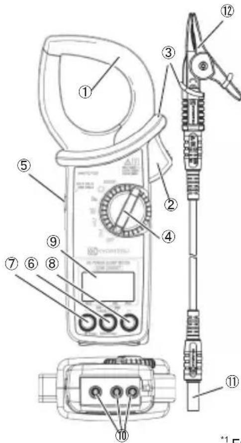
① Current sensor
② Trigger (to open/ close the jaws)
③ Barrier
Provides protection against electrical shock and ensuring the minimum required clearance and creepage distances. Always keep your fingers behind the barrier.
④ Function switch
Turn and select the desired measurement function. This switch also works as power switch: set it to "OFF" to turn off the instrument.
⑤ Data hold switch
Holds the displayed readings. The LCD shows "H" symbol while the result is being held in the display.
⑥ Mode button*1,2
Toggles the displayed results in the sequences: MAX: maximum value -> MIN: minimum value -> AVG: average value -> |PEAK|: crest factor (absolute value).
⑦ Backlight button ✱ (1sec) [◀]*2
A long press turns on/off the backlight.
⑦⑧ Item switching button [◀▶]*
A short press toggles displayed items in sequences.
*1 Function ranges, related to current measurements, are fixed while the LCD is showing MAX/ MIN/ AVG/ |PEAK| (absolute value). The auto-ranging function is reactivated when switching the display to instantaneous value.
*2 Buttons ⑥ to ⑧, ⑦ excluded, work differently depending on the selected measurement function. For further detail, see clause 3.2 Buttons and switches, P. 9, and explanations about each function.
⑨ LCD
Field effect LCD with backlight
⑩ AC voltage input terminal
Connect the plug ⑪ of test lead (M-7290) to the corresponding terminal depending on the wiring configuration to be tested.
⑪ Plug
⑫ Alligator clip
Chapter 3 Basic operation
3.1 Function switch
| Function Description | ||
| SETUP | Settings | Changes and confirms the settings for wiring, VT/ CT ratio, buzzer on/ off, backlight on/ off, nominal frequency 50/ 60Hz. To restore all the settings to the default conditions, perform system reset. |
 | Phase detection | Tests and shows the phase rotation sequence, and missing phase if there is any. |
 | Harmonics | Shows voltage/ current (of the 1st fundamental waveform up to 30th harmonics) RMS value, content rate, and distortion factor [THD-R/THD-F]. |
 | Power | Shows: active/ reactive/ apparent power, power factor, voltage-current phase differences, and voltage/ current (RMS) value. |
 | AC voltage | Shows AC voltage RMS value, peak value, and frequency. |
 | AC current | Shows AC current RMS value, peak value, and frequency. |
3.2 Buttons and switches
| Function | Buttons and switches | Details |
| --- | Data hold button | Hold down the Data hold button until the LCD shows “H symbol: then the currently displayed value is held. While this function is activated, readings don’t change even the input value varies. To exit from the hold mode, press the data hold button again or switch the measurement functions: the “H symbol disappears. |
| Backlight button※(1arc) [◀] | A long press turns on/ off the backlight. | |
| SETUP | Item switching button [◀▶] | Toggles displayed items and changes the setting values. |
| Mode button | Selects setting items and confirms the entered values. | |
| Harmonics | Item switching button [◀▶][▶] | A short press toggles display: <-> THD-F <-> THD-R <-> 1st fundamental wave to 30th harmonics.A long press switches voltage and current RMS values. |
| Mode button | A short press toggles display: <-> Inst value <-> MAX <-> MIN <-> AVG.A long press resets measurements of MAX, MIN, and AVG values and resume a measurement. | |
| Power1P2W1P3W | Item switchingbutton [◀▶] | A short press toggles display: <-> active power, power factor <-> active power, voltage-current phase differences <->active and apparent power <-> active and reactive power <-> current and voltage RMS. |
| Mode button | A short press toggles display: <-> Inst value <-> MAX <->MIN <-> AVG.A long press resets measurements of MAX, MIN, and AVG values and resume a measurement. | |
| Power3P3W3P4WBalance | Item switchingbutton [◀▶] | A short press toggles display: <-> active power, power factor <-> active and apparent power <-> active and reactive power <-> current and voltage RMS. |
| Mode button | A short press toggles display: <-> Inst value <-> MAX <->MIN <-> AVG. A long press resets measurements of MAX, MIN, and AVG values and resume a measurement. | |
| Power3P3WUnbalance | Item switchingswitchingbutton [◀▶] | A short press during a measurement:Switches the phase to be measured from R(L1) to T(L3).A short press while displaying the measured result:Toggles displays: <-> Three-phase active power <->R(L1)-phase active power <-> T(L2)-phase active power. |
| Mode button | A short press during a measurement: Switches between active power and voltage and current values (RMS).A long press while displaying the measured result:Clears the displayed values and resume a measurement. | |
| Power3P4WUnbalance | Item switchingbutton [▶] | A short press during a measurement:Switches the phase to be measured: R(L1) -> S(L2) -> T(L3).A short press while displaying the measured result:Toggles displays: <-> active power, power factor <-> active and apparent power <-> active and reactive power. |
| Mode button | A short press during a measurement: Switches between active power and voltage and current values (RMS).A long press while displaying the measured result:Clears the displayed values and resume a measurement. | |
| ~V~A | Mode button | A short press toggles display: <-> Inst value <-> MAX <->MIN <-> AVG <-> |PEAK| (peak value*).A long press resets measurements of MAX, MIN, AVG, and |PEAK| values and resume a measurement.* |PEAK|: Shows the instantaneous peak value in absolute value. |
3.3 Symbols displayed in LCD
| Symbol | Details |
 | Battery indicator: shows remaining battery in 4 levels. |
 | Bluetooth is available. (KEW2062BT only) |
 | LCD display update is held. |
 | Unbalance measurement has been selected. Nothing is displayed for balance measurement. |
 | Wiring configuration. No indication for single-phase. |
 | Total power: when “either “P1” or “P2” is displayed, it indicates the power of the single-phase according to the display. |
 | Buzzer is disabled. |
 | Type of total harmonics distortion factor. |
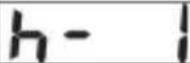 | Harmonics order: shows 1st (h-1) fundamental wave to 30th (h-30). |
 | VT ratio other than 1/1 has been set. |
 | CT ratio other than 1/1 has been set. |
 | Appears to indicate the type of measured value. |
 | LCD displays the preset nominal frequency at harmonics measurement. If set 50Hz, LCD displayed “50Hz”. |
| Negative (-) or positive (no symbol) mark is displayed according to the polarity of a measured value. For further detail, please see “9.3 Measurement specifications”. |
3.4 Unit of measured value
| Unit | |||||
| V | RMS voltage | A | RMS current | Hz | Frequency |
| kW | Active power | kVar | Reactive power | kVA | Apparent power |
| PF | Power factor | deg | V-A phase difference | % | Harmonics content rate |
Chapter 4 Getting started
4.1 Turning on KEW 2062 / 2062BT
Note
- If the instrument is in powered-off state, though the function switch is set to any measurement range, auto-power off function might be activated. Turn the function switch to OFF, and then set the switch to the desired position to wake up the instrument.
Even though the instrument doesn't wake up, the installed batteries may be totally exhausted. Please replace the batteries with new ones and try again.

When setting the function switch to any position other than "OFF", KEW 2062 / 2062BT gets started and all the LCD segments are displayed for 1 sec.
Confirm that there're no chips of segments.
4.2 Battery level check
DANGER
- Never try to replace batteries during a measurement.
WARNING
- Before opening the battery compartment cover for battery replacement, disconnect all test leads from the instrument and set the function switch to "OFF".
- Do not replace batteries if the instrument is wet.
- Accurate measurement results cannot be obtained while the battery warning indicator "☐" is blinking. Stop using the instrument and replace the batteries with new ones immediately. If the batteries are totally exhausted, the LCD doesn't show anything nor "☐" symbol.
CAUTION
- Brand and type of the batteries should be harmonized.
- Never mix new and old batteries.
• Install batteries in correct polarity as marked inside the battery compartment area.
LCD indication/ Battery level indicator
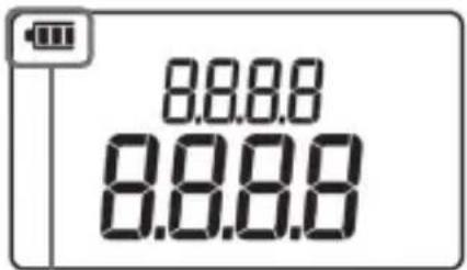
| Band | Status | Details | |
 | Battery level is full. | ||
| Indicator varies depending on the battery level. | |||
| Battery level is low. Replace the batteries with new ones. | |||
 | Battery level is extremely low, and the instrument doesn't work normally. Stop using the instrument and replace the batteries with new ones immediately.The instrument continues measurement even in this state; however, Bluetooth will be disabled. | ||
How to install batteries:
Follow the procedures below and insert batteries.
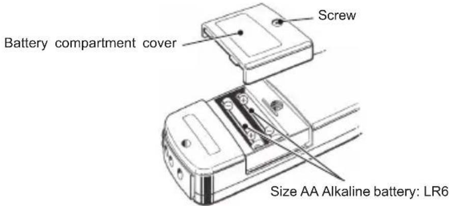
1 Disconnect all cables and set the function switch to OFF position.
2 Loosen one battery compartment cover-fixing screw and remove the cover.
3 Take out all the batteries.
4 Insert two new batteries, size AA alkaline: LR6, observing correct polarity.
5 Install the cover, and then secure it with the screw.
4.3 Test leads connection (to KEW 2062 / 2062BT)
The followings should be checked before the connection.
DANGER
- Use only the test leads supplied with this instrument.
- Connect the cables that are required for the desired measurement only.
- First, connect the plug of the test lead to the instrument. Only then connect to the measurement line.
- Never disconnect the test lead from the voltage input terminal of the instrument during a measurement (while the instrument is energized).
WARNING
- Never attempt to make measurement if any abnormal conditions are noted, such as a crack or exposed metal parts.
CAUTION
- Confirm that the instrument is powered off, and then connect the test leads.
- Connect to the instrument first, firmly into the corresponding terminal.

Connect the test leads per the following procedures.
1 Ensure that KEW 2062 / 2062BT is turned off.
2 Connect the test lead to AC voltage input terminal on the instrument.*
* The number of test leads to be connected depends on the wiring configuration.
4.4 Connection to the measured object
The following should be checked before the connection.
DANGER
- This instrument is rated to 300 V AC for CAT IV, 600 V AC for CAT III, and 1000V AC for CAT II. With attention to the measurement category to which the object under test belongs, do not make measurements on a circuit in which voltage exceeds these values.
- Use only the test leads designed for this instrument.
• Always connect the test leads to the instrument first. - When the instrument and the test lead are combined and used together, whichever lower category either of them belongs to will be applied. Pay attention to the rating of the instrument and test lead used together.
- Connect the cables that are required for the desired measurement only.
- Current sensor shall be connected to the secondary side of the circuit breaker since the primary side has dangerous large current capacity.
DANGER
- Care should be taken so as not to short-circuit the power line with the metal ends of the test lead at connection. In addition, do not touch the metal tips.
- The tips of the current sensor jaws are designed so as not to short-circuit the power line of the object to be tested but be careful when measuring an un-insulated conductor.
- Keep your fingers behind the barrier during a measurement.
Barrier: provides protection against electrical shock and ensuring the minimum required clearance and creepage distances.
For accurate measurement:
- The declared measurement accuracy is guaranteed where the conductor to be measured is placed at the center of the current clamp sensor.
- Care should be taken so as not to pinch the conductors with the tips of the jaws.
- Confirm and harmonize the wiring configuration of the measurement line and KEW 2062 / KEW2062B T.
-
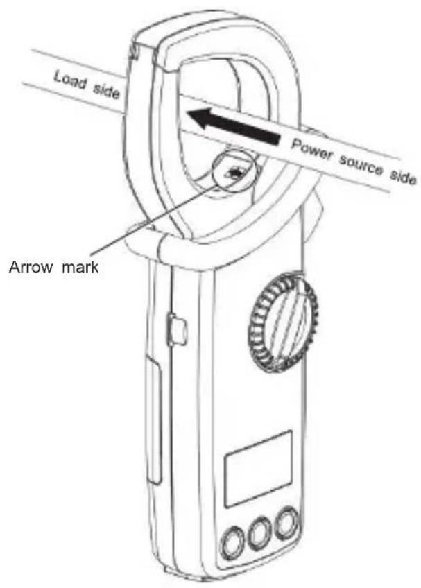
When clamping onto a conductor, make the arrow mark point towards the load side; otherwise, polarity of active power (P) will be reversed and displayed.
-
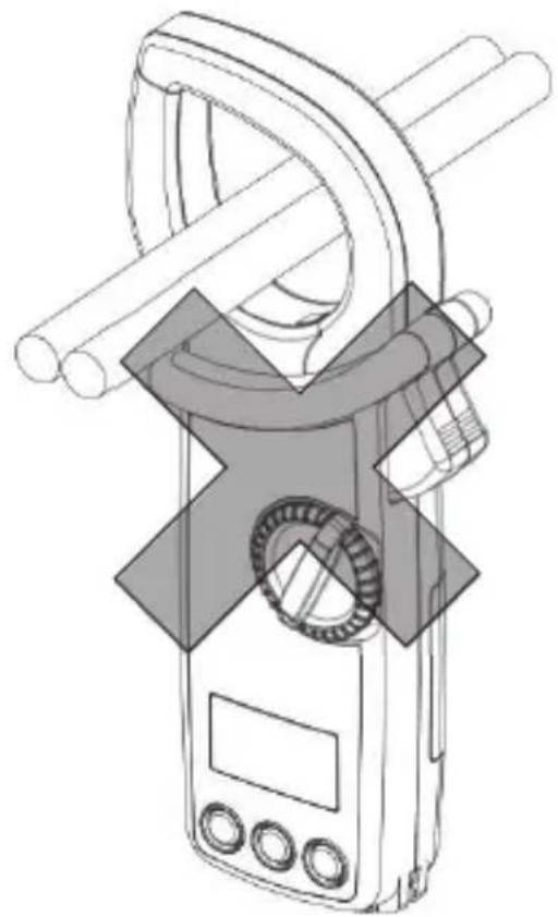
Never clamp two or more conductors.
natural_image
Technical line drawing of a handheld device with coiled pipes and a central mechanical component (no text or symbols)Chapter 5 Settings

Before starting a measurement, adjust the following settings. * Wiring configuration, frequency of the voltage to be measured, and VT/ CT ratio, if necessary.
Set the functin switch to " " to adjust settings.
Note
- Turning the function switch before confirming the altered settings clears all the changes you made. Confirm the altered settings, and then turn the function switch.
Item selection (Switch the displayed items)

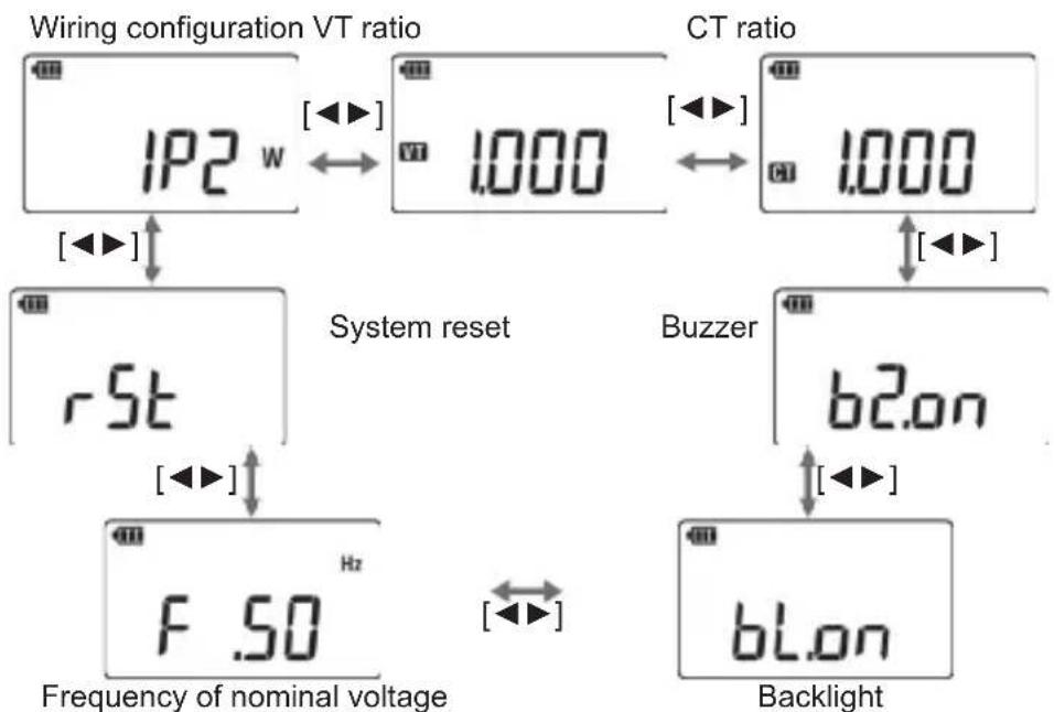
Press the item switching button [◀▶] to toggle the displayed items and confirm the desired item with the mode button. Alter the values of each item with the item switching button [◀▶], and then press the mode button again to confirm the change. The display returns to the selection screen.
Item switching button [◀▶]: toggles setting items
Mode button : confirms selection and change.
The followings are the default settings. System reset restores the altered changes to the default.
flowchart
graph TD
    A["Wiring configuration VT ratio"] --> B["IP2 w"]
    B --> C["1.000"]
    C --> D["CT ratio"]
    D --> E["1.000"]
    E --> F["rSt"]
    F --> G["FSO Hz"]
    G --> H["Buzzer"]
    H --> I["b2.on"]
    I --> J["Backlight"]
    style A fill:#f9f,stroke:#333
    style D fill:#f9f,stroke:#333
    style F fill:#ccf,stroke:#333
    style H fill:#ccf,stroke:#333
    style J fill:#ccf,stroke:#333
Wiring systems
Select "Wiring configuration" and press the mode button to adjust wiring configurations. Select the appropriate one out of five wiring configurations according to the wiring system to be tested.
* For Single-phase 3-wire(1P3W), please select "1P2W" (Single-phase 2-wire) and perform power measurement on each phase (L1/ L2) individually. KEW 2062 / 2062BT cannot show the total power of 1P3W.
Item switching button [◀▶]: toggle the available wiring configurations
Single-phase 2-wire
Balance Three-phase 3-wire
Unbalance Three-phase 3-wire
![1P2 w [◀▶] ↔ 3P3W [◀▶] 3P3 w ↔ UNB 3P3W 3P3 w [◀▶] ↔ [◀▶]](/content/2026/05/933610/images/15c445a547c5558eb29847b880df2cbfe0ad05d90822e8db52ebe1341f986eb7.jpg)
Unbalance Three-phase 4-wire
![UNB 3P4W 3P4 w ← [◀▶] 3P4W 3P4 w](/content/2026/05/933610/images/95781d43d37a2fce10dab8ab00f7d0b1294f2c797ea17279429b7e2f3a27d1ac.jpg)
Balance Three-phase 4-wire
Press the mode button while the desired wiring configuration is displayed. The selection is confirmed and the display returns to the selection screen.
VT/ CT ratio
CAUTION
- The display range, when setting VT or CT ratio, is between 0.000 and 9999 (RMS voltage/current) and between 0.000k and 9999k (power). Please take the display range into consideration when setting VT or CT ratio. If setting extremely large or small VT or CT ratio, the LCD may show 0 or OL and wouldn't change.
- Allowable input is 1100 V to AC voltage terminal and 1100 A to current sensor, regardless of selected VT or CT ratio. If output of the connected VT or CT exceeds these values, the LCD shows OL.


This setting is required if the system to be tested has external VT(s) or CT(s). The set VT/ CT ratio will be reflected to all the values measured during any measurements related to voltage and current.
While the LCD is showing VT or CT ratio, press the mode button. Then 4-digit value is displayed and the changeable digit starts blinking. Selectable range is between 0.001 and 9999.

The digit selected to be changed will blink.
A short press of item switching button [◀▶] increases or decreases the value by 1. A long press of the item switching button changes digit position (to right or left). When pressing the button, while the last digit is blinking, not a digit position but a decimal point moves. A long press of mode button while changing values or digit position cancels the changes and restores the setting to 1.000.
Press the mode button to confirm the changes. The display returns to the selection screen.
Measurement using VT/ CT ratio
DANGER
- This instrument is rated to 300 V AC for CAT IV, 600 V AC for CAT III, and 1000V AC for CAT II. With attention to the measurement category to which the object under test belongs, do not make measurements on a circuit in which the electrical potential exceeds these values.
- Always clamp the secondary side of VT or CT (transformer).
- Do not open-circuit the secondary side of CT while it is energized; otherwise, dangerous high voltage will be generated at the secondary side.
CAUTION
- When using a VT or CT, the declared measurement accuracy is not guaranteed. If using either or both of them, please take the accuracies of KEW 2062 / KEW2062BT, VT and CT, and also phase characteristics into consideration.
If voltage or current values of the measurement line exceed the max measuring range of KEW 2062 / 2062BT, the primary side value of the line can be obtained by measuring the secondary side using proper VT or CT for the specific line's voltage or current. See the diagram below.
Example:
Single-phase 2-wire (1P2W)

Buzzer ON/ OFF
Keypad sounds, and phase detection buzzer can be muted. This setting doesn't affect the low battery warning buzzer and the buzzer indicating auto-power-off is activated.
Select "Buzzer" and press the mode button. Then "ON(on)"/ "OFF(oF) starts blinking. Now it is ready to change the setting.
Item switching button [◀▶]:
on: Buzzer sounds
oF: No buzzer sounds
![b2.on ← [◀▶] b2.of](/content/2026/05/933610/images/9a0f474680ac12b4eb6d4f160c5ef30c2ee13e09c0cc39757c11a0a29f718b4e.jpg)
Press the mode button to confirm the changes. The display returns to the selection screen.
Backlight ON/ OFF
This setting is to enable or disable auto-backlight-off function if there're no key operations for the specified time.
Select "Backlight" and press the mode button. Then "ON(on)"/ "OFF(oF) starts blinking and now it is ready to change the setting.
Item switching button [◀▶]:
on: Turns off in 5 min. oF: Disables auto-off function.
![bL.on ← [◀▶] bL.ofF](/content/2026/05/933610/images/b0ed2130945602f043e851b9c2201bc5bd1eeab65b42eea3ccd8fc653a92bfb2.jpg)
Press the mode button to confirm the changes. The display returns to the selection screen.
Frequency of nominal voltage
Set the power frequency of the object to be measured.
Note
- Harmonics are calculated based on the preset frequencies. For accurate measurement, please check and set the same frequency as the power frequency of the object to be tested.
Select "Frequency of nominal voltage" and press the mode button. Then ".50[Hz]"/".60[Hz]" starts blinking; that means it is ready to change the setting.
Item switching button [◀▶]: Switches the frequencies.
![F .50 Hz [◀▶] F .60 Hz](/content/2026/05/933610/images/802e4175fccda8ec1879bb18560f984faa8a909d250cb7d078bffe1b3c938083.jpg)
Press the mode button to confirm the changes. The display returns to the selection screen.

The set nominal frequency is displayed as left figure at harmonics function.
System reset

Restore all the settings to default*. *See P.16 Item selection part. Select "System reset" and press the mode button. Then "n: Cancel" starts blinking; that means it is ready to change the setting.
Item switching button [◀▶]:
.n: Cancel
.y: Performs system reset.
![rSt.n [◀▶] ←→ rSt.P](/content/2026/05/933610/images/c0b753be44bedff056db04b2937d583c70ac2607b54e15f3c7bb6210391442eb.jpg)
Select “.y” and press the mode button. Then system reset will be done and the display returns to the selection screen. To cancel or do not want to do system reset, select “.n” and press the mode button.
Chapter 6 Display items by measurement function
6.1 RMS/ Frequency measurement
While viewing "Waveform" on your Smartphone or tablet device using our app via Bluetooth, KEW 2062BT's LCD will be like the illustration shown to the right and won't show the measured values.
To check the measured values on the instrument, switch the item on your Bluetooth device using the app from "Waveform" to "Measured value", or disconnect Bluetooth communication.

RMS current, frequency
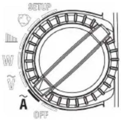
Set the function switch to “A”.
Auto-ranging function activates and switches the current range depending on the measured value.
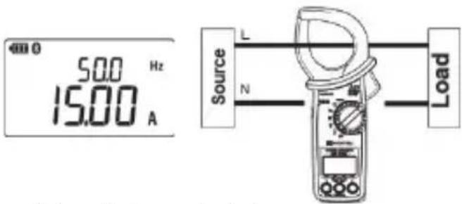
A short press of Mode button: switches display modes between Inst, MAX, MIN, AVG, and |PEAK|.
* Each of above values is determined after pressing the mode button and measurements get started.
A long press of Mode button: clears measured values (MAX, MIN, AVG, and |PEAK|).
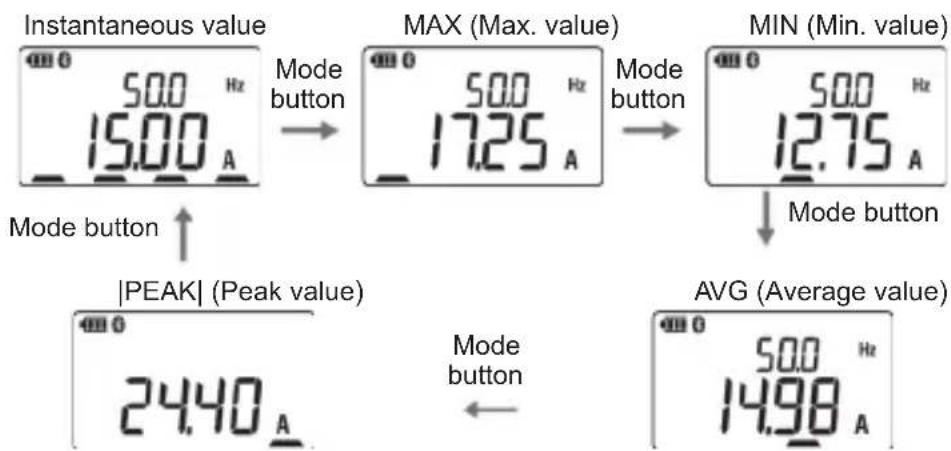
Range is fixed while the LCD is showing MAX, MIN, AVG, or |PEAK|. The auto-ranging function is reactivated when switching the display to instantaneous value.
Note
- When current is measuring current in PEAK mode, opening and closing operation of the current sensor affects the readings. To obtain accurate readings, check the readings while clamping onto the conductor to be tested or turn on the data hold function before unclamping the conductor.
- In the PEAK mode, sampling is performed in one cycle and PEAK value (crest value) is determined based on the result. The sampling is performed just once in 0.5s, therefore, the Tester cannot measure a sudden input signal such as inrush current.
RMS voltage, frequency
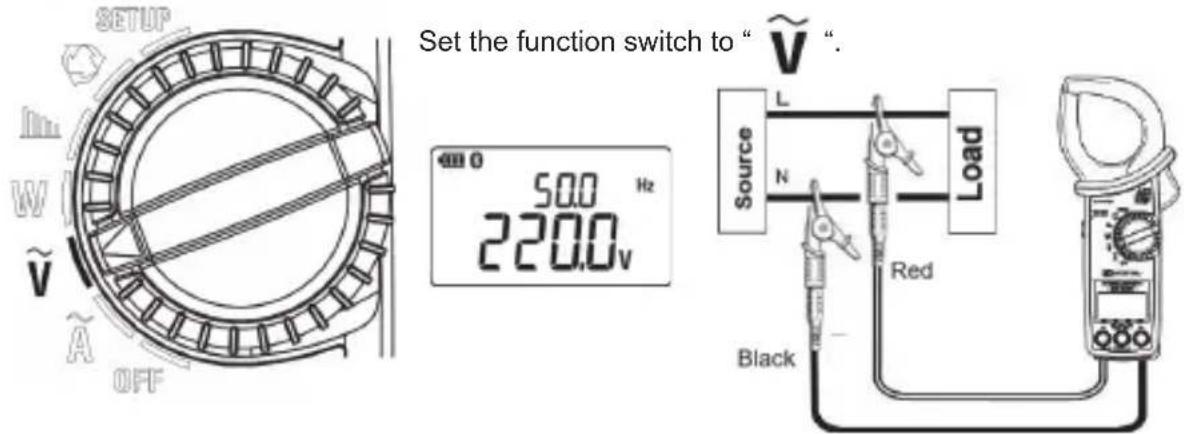
A shot press of Mode button: switches display modes
between Inst, MAX, MIN, AVG, and |PEAK|.
* Each of above values is determined after pressing the mode
button and measurement get started.
A long press of Mode button: clears measured values (MAX, MIN, AVG, and |PEAK|).

Note
- In the PEAK mode, sampling is performed in one cycle and PEAK value (crest value) is determined based on the result. The sampling is performed just once in 0.5s, therefore, the Tester cannot measure a sudden input signal such as inrush current.
6.2 Single/ Three-phase (balance) Power measurement
Note
- KEW 2062 / 2062BT cannot measure Three-phase 4-wire with different capacitors (V/ Δ -connection). To measure such a system, please test phases individually.

Set the function switch to "

Select wiring system in the selection screen.
Single-phase 2-wire (1P2W) Three-phase 3-wire (3P3W) Three-phase 4-wire (3P4W)
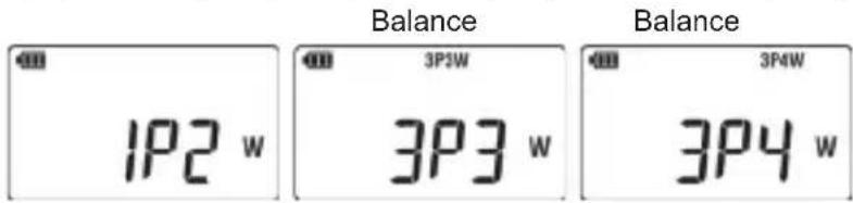
Connection diagram for Single-phase 2-wire (1P2W)

Connection diagram for Single-phase 3-wire (1P3W)
To measure Single-phase 3-wire (1P3W), select "1P2W" and measure power of L1 and L2 separately. KEW 2062 / 2062BT cannot show the total power of 1P3W.

Connection diagram for balance Three-phase 3-wire (3P3W)
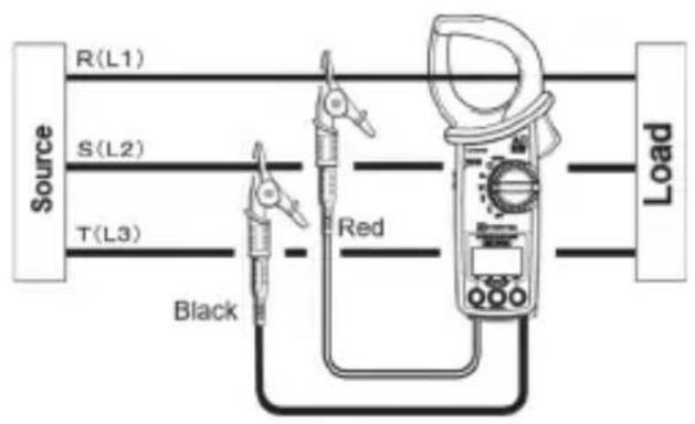
Connection diagram for balance Three -phase 4-wire (3P4W)

Switching display
Item switching button [◀▶]:
Short press: switches measured values to be displayed in the LCD.
Active power, power factor/ Active power, voltage-current phase difference/ Active, apparent powers/ Active, reactive powers/ RMS current, voltage values
Active power, power factor Active power, voltage-current Active, apparent powers
phase difference
![PF 0.980 3.23 kW [◀▶] 12.0 deg 3.23 kW [◀▶] 3.30 kVA 3.23 kW RMS current, voltage values 220.0 v 15.00 A [◀▶] Active, reactive powers 0.69 kVar 3.23 kW](/content/2026/05/933610/images/37d02ece91a7e94e4c2917a424b6542d2c03b39f09ac9011966e7f84d95d96f8.jpg)
Mode button
Short press: switches display modes between Inst, MAX, MIN, and AVG.
* Each of above values is determined after pressing the mode
button and measurements get started.
Long press: clears measured values (MAX, MIN, and AVG)
Example: Active power, power factor* screen
* Measured values displayed in the upper and lower rows are switched together.

AVG (average value) MIN (minimum value)

Range is fixed while the LCD is showing MAX, MIN, or AVG. The auto-ranging function is reactivated when switching the display to instantaneous value.
6.3 Three-phase (unbalance) power measurement
Note
- KEW 2062 / 2062BT cannot measure Three-phase 4-wire with different capacitors (V/ Δ -connection). To measure such a system, please test phases individually.
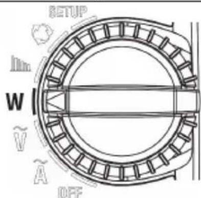
Set the function switch to "W".
Select wiring system in the selection screen.
Three-phase 3-wire (3P3W) Three-phase 4-wire (3P4W)
Unbalance

Unbalance

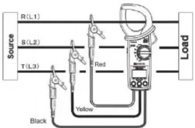
Three-phase 3-wire (3P3W) unbalance
Measurement procedures
Clamp onto R(L1) phase
![UNB 3P3W 1.5t SET Source R(L1) S(L2) Y(L3) Red Black Yellow Load [▶] UNB 3P3W 1.5t 28.07 kW Mode button UNB 3P3W 380.0 v 75.0 A](/content/2026/05/933610/images/3c3f6a09ff290370f2da47fee277241f7595bfe0a2cffe91d79cd037b1eb818e.jpg)
Clamp onto T(L3) phase
![UNB 3PJW 2nd SET R(L1) S(L2) Y(L3) Load [▶] UNB 3PJW 2nd 29.53 kW Mode button UNB 3PJW 379.5 v 77.9 A](/content/2026/05/933610/images/d34573b19c39361d764018c8cd4cc051251d1d84ef9947ca9e39c4eacbdafd84.jpg)
Result display [ ◀▶ ]
Clamp onto R(L1) phase
While the LCD is showing the settings for the first measurement, make connection as the following figure shows.

Press the item switching button [▶] after making connection, the LCD shows active power of R(L1) phase. Pressing mode button switches the indication between active power and RMS voltage/ current values of R(L1) phase.

Another press of item switching button [▶] changes measurement object from R(L1) to T(L3).
Clamp onto T(L3) phase
While the LCD is showing the 2nd time measurement screen, switch the current sensor position as shown to the right; just the sensor only, do not unclip or change the position of test leads.

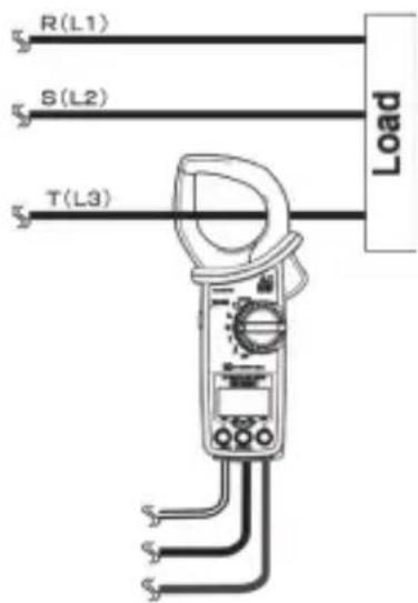
Press the item switching button [▶] after making connection, the LCD shows active power of T(L3) phase. Pressing mode button switches the indications between active power and RMS voltage/ current values of T(L3) phase.
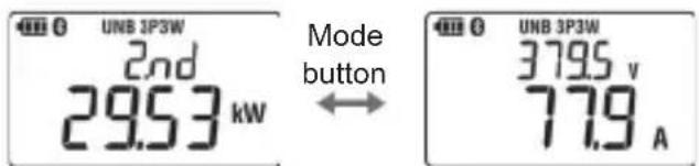
Another press of item switching button [▶] switches the screens to measurement result.
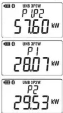
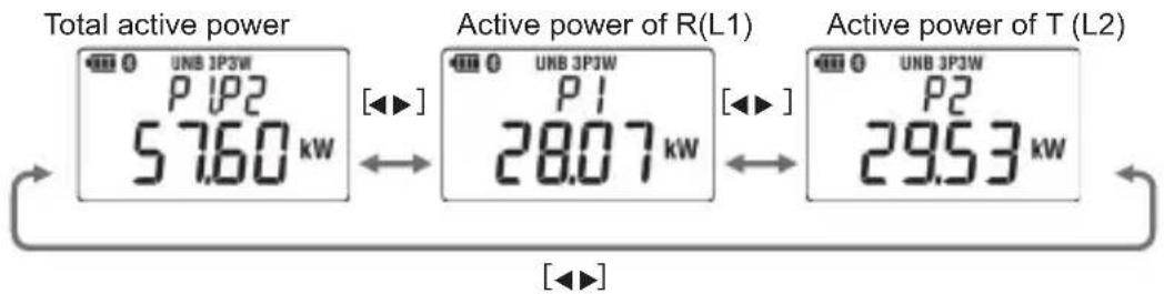
Result display
Item switching button [◀▶]:
Short press: switches measured values to be displayed in the LCD.
other
| Component | Total active power (kW) | Active power of R(L1) (kW) | Active power of T(L2) (kW) | |-----------|--------------------------|----------------------------|----------------------------| | Top Panel | 57.60 | 28.07 | 29.53 | | Middle Panel | - | - | - | | Bottom Panel | - | - | - |A long press of mode button clears measured results and the screen returns to the initial screen.
Three-phase 4-wire (3P4W) unbalance
Measurement procedures
Clamp onto R(L1) phase

flowchart
graph TD
    A["SET"] --> B["Mode button"]
    B --> C["1st 28.07 kW"]
    C --> D["Result display"]
    D --> E["3P4W 84.58 kW"]
    E --> F["P1 28.07 kW"]
    F --> G["Result display"]
    G --> H["P2 34.28 kW"]
    H --> I["P3 22.23 kW"]
    I --> J["Result display"]
    J --> K["3P4W 86.3 A"]
    K --> L["Mode button"]
    L --> M["3rd 22.23 kW"]
    M --> N["Result display"]
    N --> O["3P4W 63.8 A"]
    O --> P["Mode button"]
    P --> Q["3rd 22.23 kW"]
    Q --> R["Result display"]
Clamp onto S(L2) phase
flowchart
graph TD
    A["SET"] --> B["Load"]
    B --> C["Mode button"]
    C --> D["Mode button"]
    D --> E["36.10 v 63.8 A"]
    style A fill:#f9f,stroke:#333
    style B fill:#ccf,stroke:#333
    style C fill:#cfc,stroke:#333
    style D fill:#fcc,stroke:#333
    style E fill:#ffc,stroke:#333
Clamp onto R(L1) phase
While the LCD is showing the 1st time measurement screen, make connection as the following figure shows.

Press the item switching button [▶] after making connection, the LCD shows active power of R(L1) phase. Pressing mode button switches the indication between active power of R(L1) phase and RMS voltage/ current values.

Another press of item switching button [▶] changes measurement object from R(L1) to S(L2).
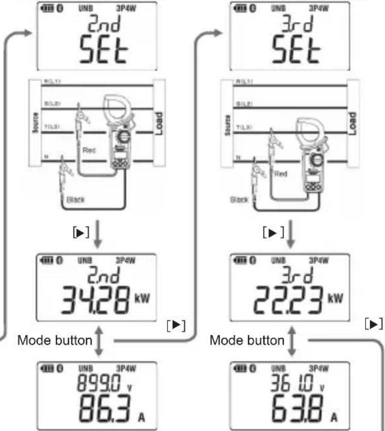
Clamp onto S(L2) phase
While the LCD is showing the settings for 2nd measurement, make connection as the following figure shows: move the current sensor and red test lead to S (L2) phase.

Press the item switching button [▶] after making connection, the LCD shows active power of S(L2) phase. Pressing mode button switches the indication between active power of S(L2) phase and RMS voltage/ current values.


Another press of item switching button [▶] changes measurement object from S(L2) to T(L3).
Clamp onto T(L3) phase
While the LCD is showing the 3rd time measurement screen, move the current sensor and red test lead to T(L3) as shown to the right.

Press the item switching button [▶] after making connection, the LCD shows active power of T(L3) phase. Pressing mode button switches the indication to RMS voltage/ current values of T(L3) phase.


Another press of item switching button [▶] switches the screens to measurement result.
Result display
Item switching button [◀▶]:
Short press: switches measured values to be displayed in the LCD.

other
| Power Factor | Component | Value (kW) | | ------------ | --------- | ---------- | | T(L3) | Active power of T(L3) | 22.23 | | T(L3) | Active power of S(L2) | 34.28 | | T(L3) | Active power of R(L1) | 28.07 | | Apparent power | Active power of T(L3) | 84.58 | | Apparent power | Active power of S(L2) | 85.93 | | Apparent power | Active power of R(L1) | 13.90 | | Reactive power | Active power of T(L3) | 84.58 | | Reactive power | Active power of S(L2) | 85.93 | | Reactive power | Active power of R(L1) | 13.90 | The diagram shows a multi-step transformation of the 'Active power' components.A long press of mode button clears measured results and the screen returns to the initial measurement setting screen.
6.4 Harmonics measurement

Set the function switch to " .
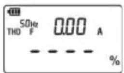
The nominal frequency is displayed as right figure at harmonics function. Nominal frequency can be set to 50Hz or 60Hz on SET UP function. (See P.19 "Frequency of nominal voltage".)
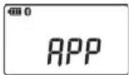
The LCD screen will be as the right figure shows during Bluetooth communication: no measured values are displayed. The measured values can be checked by using the application on your smartphone or tablet device, or by disconnecting the Bluetooth.
Current harmonics distortion factor, content rate, RMS value
Current measurement ranges switches automaticay deoending on the measured value.

When the unit shown in the LCD is "V", it means the screen is "voltage harmonics measurement screen". Hold down (long press) the Item switching button [▶] to switch the unit to "A".
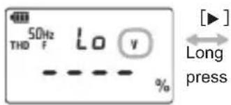

[Item switching button [◀▶]]
A short press toggles the displayed measured values:
RMS/ Harmonics distortion factor THD-F, RMS/ Harmonics distortion factor THD-R, 1st fundamental wave RMS/ content rate to 30th harmonics RMS/ content rate
RMS/ Harmonics distortion factor THD-F
![THD 50Hz THD F 17.25 A 15.0 % [◀▶] ↔ [◀▶]](/content/2026/05/933610/images/095853af3d33e9e9c218d7244a56cb256a74409c6c4dee04144a026aa83a0702.jpg)
RMS/ Harmonics distortion factor THD-R
![S0Hz THO R 17.25 A 13.0 % [◀▶]](/content/2026/05/933610/images/b083c1ef6a5f9b2841fd65c32ba44fdcd9cfcd0b04ff89e0706fb50d97df8cd8.jpg)
30th harmonics RMS/ content rate to
![SDHz h-30 0.0 % ~ [◀▶] ↔](/content/2026/05/933610/images/8388c0ab723672e6af828cd5c6d9c3a9340dcb9ce03a9eaa9e7bded60485d461.jpg)
1st fundamental wave RMS/ content rate
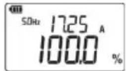
The upper row shows the order of the harmonics (1h to 30h) and RMS of each harmonics: these two switches every second.
[ Mode button ]
A short press switches display mode between Inst, MAX, MIN, and AVG.
Each of above values is determined after pressing the mode button and measurements get started.
A long press of the button clears measured values (MAX, MIN, and AVG).
Example: Display screen of RMS/ Harmonics distortion factor THD-F*
* Measured values displayed in the upper and lower rows switch simultaneously in every screen.

AVG (Average value) MIN (Minimum value)

Range is fixed while the LCD is showing MAX, MIN, or AVG. The auto-ranging function is reactivated when switching the display to instantaneous value.
Voltage harmonics distortion factor, content rate, RMS value

When the unit shown in the LCD is "A", it means the screen is "current harmonics measurement screen". Hold down (long press) the Item switching button [▶] to switch the unit to "V".

[▶]
Long
press

[ Item switching button [◀▶] ]
A short press toggles the displayed measured values:
RMS/ Harmonics distortion factor THD-F, RMS/ Harmonics distortion factor THD-R, Fundamental wave RMS/ content rate to 30th harmonics RMS/ content rate
RMS/ Harmonics distortion factor THD-F
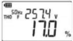


RMS/ Harmonics distortion factor THD-R


30th harmonics RMS/ content rate to
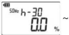


Fundamental wave RMS/ content rate
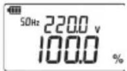
The upper row shows the order of the harmonics (1h to 30h) and RMS of each harmonics: these two switches every second.
[ Mode button ]
A short press switches display mode between Inst, MAX, MIN, and AVG.
Each of above values is determined after pressing the mode button and measurements get started.
A long press of the button clears measured values (MAX, MIN, and AVG).
Example: Display screen of RMS/ Harmonics distortion factor THD-F*
* Measured values displayed in the upper and lower rows switch simultaneously in every screen.

AVG (Average value) MIN (Minimum value)

Harmonics distortion factor THD-R/THD-F
There are two typical definitions used when dealing with Total Harmonic Distortion (THD). The two types of Total Harmonic Distortion are THD-F and THD-R. THD-F uses fundamental wave forms and THD-R uses total RMS values as a reference.
THD-F _ [%] = RMS harmonics(2nd to...) Fundamental RMS value(1st) × 100
THD - R _ [%] = RMS harmonics(2ndto...) Fundamental RMS value + RMS harmonics × 1 0 0
They both are figures of merit used to quantify harmonic levels in voltage and current waveforms; however, the THD-R measurement can be prone to misinterpretation which can easily lead to measurement errors when measuring larger distortions. That is, at low distortion levels, the difference between the two calculation methods - THD-F and THD-R - is negligible but at large distortion levels, THD-F can get more accurate results.
With the former measuring devices, accurate measurement of RMS fundamental wave (first order only), which is required for THD-F calculation had been difficult; therefore, THD-R has been commonly used. Although, recent devices can measure it accurately. So now in practice, THD-R is used for simple measurements and the distortion factor of THD-F, less susceptible to harmonics content rate against specified measurement accuracy, is commonly used.
Where investigating what causes harmonics on load side, THD-R measurement if often used, and for power quality control purpose, the THD-F is mainly used.
6.5 Phase detection
Note
- KEW 2062 / 2062BT cannot measure Three-phase 4-wire with different capacitors (V/ Δ -connection).
- When setting the buzzer to "OFF", buzzer doesn't sound at the end of detection process. If buzzer indication is required for phase detection judgement, set the buzzer to "ON".

Set the function switch to “ ↗”.

flowchart
graph TD
    A["Source"] -->|R(L1)| B["Load"]
    A -->|S(L2)| B
    A -->|T(L3)| B
    A -->|N| B
    B -->|Red| C["Yellow"]
    B -->|Black| D["Black"]
According to the wiring system of Three-phase 3-wire and Three-phase 4-wire to be tested, the results are displayed as the following table shows. Each number represents the connected phase order.
| Wiring system | R(L1) | S(L2) | T(L3) | Indication | Judgement Buzzer |
| Positive phase | Live | Live/ Earth | Live | 1.2.3 | Discontinuous: Pi, Pi, Pi |
| Negative phase 3.2.1 | Continuous: Piii | ||||
| Unjudgeable | Missing phase, abnormal frequency, out of voltage effective input range, unbalance | --- | Not sound. | ||
Chapter 7 Other functions
[Data hold function]
The LCD shows “H” in the upper left corner by pressing data hold button and hold the currently displayed reading. In this state, the instrument is performing measurements; however, the reading isn’t updated. Press the Data hold button again to exit from the data hold mode, then treading update resumes and the “H” disappears.
By switching the measurement function, data hold is disabled, and measurement starts on the selected function.
[Auto-backlight-off]
Backlight turns off automatically when 5 min. pass after the last key operation. To turn it on again, hold down (long press) the Item switching button [◀]. Then the lighting time will be extended 5 min. A long press of Item switching button [◀], while the light is on, turns off the light. When setting the backlight to OFF, written in page 19, the auto-off function is disabled. In this state, backlight doesn't turn off when 5 min pass. To turn off the light, in this case, hold down the Item switching button [◀].
[Auto-power-off]
Note
- If the instrument is off with the function switch set to a measurement position, auto-power-off function might activate and turn off the instrument.
Except for Bluetooth communication, the instrument turns off automatically when 15 min. pass after the last key operation; discontinuous buzzer sounds 4 times. To turn on the instrument again, set the function switch to OFF and then set it to the desired measurement position.
[Auto-ranging – current]
Current range switches automatically according to the measured rms currents.
A range shifts to one upper range when the input exceeds 110% or 300% peak (absolute value) of the currently selected range and shifts to one lower range when the input drops 90% rms. While “MAX”, “MIN”, “AVG”, and “|PEAK| (peak value)” has been selected in the display mode, auto-ranging doesn’t work: the selected range is fixed and used.
Chapter 8 Bluetooth communication

WARNING
- Radio waves at Bluetooth communication may affect the operations of medical electronic devices. Special care should be taken when using Bluetooth connection in the areas where such devices are present.
Note
- Using the instrument or tablet devices near wireless LAN devices (IEEE802.11.b/g) may cause radio interferences, lowering of communication speed, resulting in significant time lag in the display update rate between the instrument and tablet device. In this case, keep the instrument and the tablet device away from the wireless LAN devices, or turn off the wireless LAN devices or shorten the distance between the instrument and the tablet device.
- It may be difficult to establish communication connection if either the instrument or tablet device is in a metal box. In such a case, change the measurement location or remove the metal obstacle between the instrument and the tablet device.
- If any leaking of data or information occurs while making a communication using Bluetooth function, we assume no responsibility for any released content.
- Some tablet devices, even if the application runs properly, may fail to establish communication with the instrument. Please use another tablet device and try to communicate with. If you still cannot confirm the connection, there may be some problem with the instrument unit. Please contact your local KYORITSU distributor.
- The Bluetooth word mark and logos are owned by Bluetooth SIG, Inc. and we, KYORITSU, are licensed by them for use.
- Android, Google Play Store, and Google Map are the trademark or registered trademark of Google Inc.
- iOS is the trademark or registered trademark of Cisco.
- Apple Store is the service mark of Apple Inc.
- In this manual, the "TM" and "®" marks are omitted.
KEW 2062BT has a Bluetooth communication function and can exchange data with Android/iOS tablet devices. Using the special application "KEW Power*(asterisk)" enables remote monitoring/checking data.
First, download the application "KEW Power*(asterisk)" via the internet. Some functions are available only while connected to the internet. For further detail, please refer to "8.1. KEW Power* (asterisk) features".
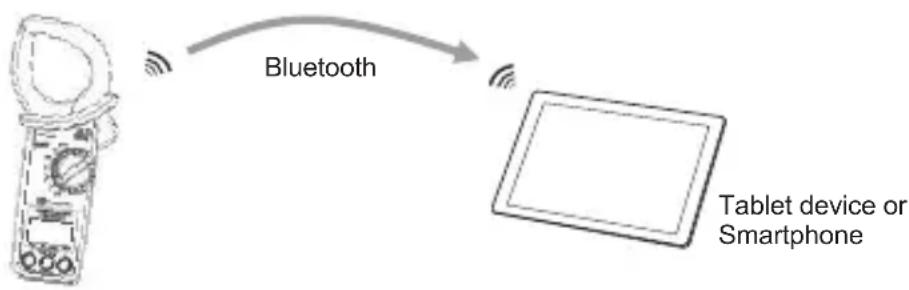
flowchart
graph LR
    A["Tablet device or Smartphone"] -->|Bluetooth| B["Smartphone"]
8.1 KEW Power\*(asterisk) features
KEW Power\*(asterisk) for KEW 2062BT
The special application “KEW Power*” is available on download site for free. (An Internet access is required: Android tablets, via Google Play Store and iOS devices, via App Store). Please note that communication charge is incurred separately for downloading applications and using special features of them. For your information, “KEW Power*” is provided on-line only.
Main features of KEW Power*:
(1) Remote monitoring/ checking
(2) Data save/ recall function
(3) Input wave form display of voltage and current
(4) Graphical display of harmonics rms values and content rate
(5) Pass/ fail judgement of measured value
Chapter. 9 Specifications
9.1 Safety specifications
| Location for use | : Altitude 2000 m or less, in-door use |
| Accuracy guaranteed | |
| Temp. & Hum. range | : 23ircC ± 5ircC , Relative humidity 85% or less (no condensation) |
| Operating Temp. &: | :- 10ircC to + 50ircC , 85 % or less (no condensation) |
| humidity range | |
| Storage Temp. & humidity range | :- 20ircC to + 60ircC , 85 % or less (no condensation) |
| Withstand voltage | : 5160 V AC/ 5 sec.(between current sensor and enclosure or electrical circuit and enclosure) |
| Insulation resistance | : 50 MΩ or more/ 1000 V (between electrical circuit and enclosure) |
| Applicable standards | : IEC 61010-1, -2-032 (main unit)/ -031 (test leads)Measurement CAT IV 300 V/ CAT III 600 V/ CAT II 1000VPollution degree 2,IEC 61326(EMC) Class B, EN50581 (RoHS),EN 301 489-1, EN 300 328, EN 62479, andIEC 60529 IP40 |
9.2. General specifications
Readings update rate : Approx. 0.5 sec. on , , W, and functions, Approx. 1.0 sec.

| Max. conductor size | :ø55 mm (max) |
| Dimension | :247(L) × 105(W) × 49(D) mm |
| Weight | :Approx. 490g (including batteries) |
| Accessories | :Test lead MODEL 7290 / alligator clip (red, black, yellow,)...... 1 set Instruction manual...... 1 pce. Alkaline size AA battery (LR6)...... 2 pcs. Soft case MODEL9198...... 1 pce. |
| Continuous operating time | :Approx. 58 hours (W function, continuous measurement, no load, backlight off, using alkaline size AA (LR6) batteries) |
| Current consumption | :35 mA typ. (@3.0 V, W function) |
| Communication | :Bluetooth® Ver5.0 (KEW2062BT only) |
9.3 Measurement specifications
AC current function

RMS AC current value (ACA) [Arms], Peak value (Absolute value)
[A|peak]
| Range | 40.00 A/ 400.0 A/ 1000 A*Auto-ranging, range won't be fixed.A range shifts to one upper range when the input exceeds 110% or 300% peak (absolute value) of the currently selected range and shifts to one lower range when the input drops 90% rms.Where any of “MAX”, “MIN”, “AVG”, or |PEAK| (peak value) has been selected in the display mode, the selected range is fixed. | |
| Display digit | 4-digit | |
| Sampling period | 1 cycle/ 500ms | |
| Sampling frequency | 32.8 kHz(30.5 μs interval)PEAK value: moving average is 9 points between 40.0Hz and 70.0Hz only. | |
| Effective input range | 40.00A range RMS: 0.60 A to 40.00 A, PEAK value: ±(0.6 A to 56.57 A)400.0A range RMS: 6.0 A to 400.0 A, PEAK value: ±(6.0 A to 565.7 A)1000A range RMS: 60 A to 999.9 A, PEAK value: ±(60 A to 1414 A) | |
| Display range | RMS value: 40.00A range :0.30 to 44.00 A400.0A range :3.0 (36.0 A*) to 440.0 A1000A range :30 (360 A ) to 1100 A*While auto-ranging is enabled, values displayed with “()” will be effective, and the LCD shows “0” when the input is less than 0.30 A and “OL” when 1100 A is exceeded.PEAK value (absolute value): 40.00A range : 0.30 A to 120.0 A400.0A range : 3.0 A to 1200 A1000A range : 30 A to 1500 A | |
| Crest factor | 3 or less on 40.00A/400.0A range, 3 or less 1500 A peak on 1000A range | |
| Accuracy | RMS: (sine wave) 40.0 to 70.0 Hz: ±1.0%rdg±3dgt70.1 to 1 kHz: ±2.0%rdg±5dgt* Add ±0.5%rdg±5dgt to the accuracy for sine waves other than 40 to 70 Hz.PEAK value (absolute value): 40.0 to 70.0 Hz: ±2.5%rdg±5dgt70.1 to 1 kHz: ±4.0%rdg±5dgt | |
| Formula | i : Sampling point No.n : Number of samples/ cycle | |
Current frequency (Af) [Hz]
| Display digit | 4-digit |
| Accuracy | ± 0.3%rdg ± 3dgt (40.0Hz to 999.9Hz, sine wave) |
| Effective input range | Within sine wave of 40.0Hz to 999.9Hz, ACA effective input range. |
| Display range | 40.0 to 999.9HzThe LCD shows “---” when readings are out of the display range or display range of ACA). |
AC Voltage function

RMS AC voltage value (ACV) [Vrms], Peak value (Absolute value) [V|peak]
| Range | 1000V |
| Display digit | 4-digit |
| Sampling period | One cycle/ 500 ms |
| Sampling frequency | 32.8 kHz (every 30.5μs)PEAK value: moving average is 9 points between 40.0Hz and 70.0Hz only. |
| Effective input range | RMS: 30.0 V to 999.9 V Peak value: ±(30.0 V to 1414 V) |
| Display range | RMS: 30.0 V to 1100 VPeak value (absolute value): 30.0 V to 1555 V* The LCD shows “Lo” when readings are below the lower limit and “OL” when over the upper limit. |
| Crest factor | 1.7 or less |
| Accuracy | RMS: sine wave 40.0 to 70.0 Hz: ±0.7%rdg±3dgt70.1 to 1 kHz: ±3.0%rdg±5dgt* Add ±0.5%rdg±5dgt to the accuracy for sine waves other than 40 to 70 Hz.PEAK value (absolute value): 40.0 to 70.0 Hz: ±2.5%rdg±5dgt70.1 to 1 kHz: ±4.0%rdg±5dgt |
| Input impedance | Approx.4 MΩ * resistance value across the terminals |
| Formula |  Connect and measure L=V1, N=V3i : Sampling point No.n : Number of samples/ cycle Connect and measure L=V1, N=V3i : Sampling point No.n : Number of samples/ cycle |
Voltage frequency (Vf) [Hz]
| Display digit | 4-digit |
| Accuracy | ±0.3%rdg±3dgt (40.0 Hz to 999.9 Hz, sine wave) |
| Effective input range | Within sine wave of 40.0Hz to 999.9Hz, ACV effective input range. |
| Display range | 40.0 to 999.9 HzThe LCD shows “---” when readings are out of the display range or display range of ACV). |
| Signal source | V1 to V3 (voltage across terminals) or A |
Power function W
Active power (P) [W]
| Range | 40.00kW/400.0 kW/1000 kW* Switched according to the selected current range. | |
| Display digit | 4-digit(The LCD shows "----" if the reading is out of the guaranteed accuracy range.) | |
| Sampling period | 1 cycle/ 500ms | |
| Sampling frequency | 32.8 kHz(30.5 μs interval) | |
| Effective input range | Effective input range of RMS voltage, and RMS current and within the frequency range of 45 to 65 Hz. | |
| Display range | 40.00kW range : 0.00 to 44.00 kW400.0kW range : 0.0 (36.0 kW) to 440.0 kW1000kW range : 0 (360 kW) to 1210 kW* Currently selected range is fixed if you select MAX, MIN, or AVG in display mode.* Values within parenthesis will be displayed while auto-ranging function is activated, and “---” will be displayed when readings are out of the display range of RMS voltage or RMS current and effective input frequency. | |
| Accuracy | For sine wave with power factor 1 : ±1.7%rdg±5dgtinfluence of phase angle within ±3.0°where: within the effective input range for ACV and ACAfunctions, PF: 1, sine wave, and 45 – 65 Hz)* Sum value: Total errors determined by each measurement channels.(doubled: 3P3W, tripled: 3P4W) | |
| Polarity sign | Consumption (flow-in): no sign, Regeneration(flow-out): - | |
| Formula | P = 1n ( i=0n-1 (Vi × Ai) ) | V is used as reference,i : Sampling point No.n : Number of samples/ cycle |
| Wiring system | Display value | Destination |
| 1P2W·1P3W | P | 1P2W:L=V1·A ,N=V31P3W: L1/L2=V1·A, N=V3 |
| Balance 3P3W | Psum(=Ssum×cos(θ)) | R=V1·A, S=V3 |
| Balance 3P4W | Psum(=P×3) | R=V1·A, N=V3 |
| Unbalance 3P3W | P1、P2、Psum(=P1+P2) | P1 :R=V1·A, S=V2, T=V3P2 :R=V1 ,S=V2, T=V3·A* Change the connected points twice and test (2-wattmeter method) |
| Unbalance 3P4W | Displayed only when measuring each phase: P1, P2, P3Total value: Psum(=P1+P2+P3) | P1: R=V1·A, N=V3P2: S=V1·A, N=V3P3: T=V1·A, N=V3* Change the connected points three times and test |
Apparent power (S) [VA]
| Range | Same as the active power | |
| Display digit | Same as the active power | |
| Effective input range | Same as the active power | |
| Accuracy | ±1dgt to the result determined by each measured value* Sum: add errors of each channel, 3P3W: ±2dgt, 3P4W: ±3dgt | |
| Polarity sign | No sign | |
| Formula | S=V×A * When P >S, P=S. | |
| Wiring system | Display value | Destination |
| 1P2W·1P3W | S | Same as the active power |
| 3P3W (balance) | Ssum(=S×3) | |
| 3P4W (balance) | Ssum(=S×3) | |
| 3P4W (unbalance) | Ssum(=S1+S2+S3) ※ Sn : Apparent power at the nth measurement | |
Reactive power (Q) [Var]
| Range | Same as the active power | |
| Display digit | Same as the active power | |
| Effective input range | Same as the active power | |
| Accuracy | ±1dgt to the result determined by each measured value* ±2dgt when measuring balance 3P3W, ±3dgt when measuring balance 3P4W | |
| Polarity sign | Phase delay: no sign, Phase advance: - | |
| Formula | Q=√S2-P2* Where P >S, P=S.* Q=0 when □P□>S.* Polarity symbol is displayed depending on the current phase angle with the voltage phase (0°) as reference. See the followings.0° to -90° to180°: No sign (+) Phase delay0° to +90° to 180°: Negative (-) Phase advance*When |P|>S, Q=0.* Polarity symbol is displayed depending on the voltage-current phase difference (θ).0° to -90° to180°: No sign (+) Phase delay0° to +90° to 180°: Negative (-) Phase advance | |
| Wiring system | Display value | Destination |
| 1P2W·1P3W | Q | Same as the active power |
| 3P3W (balance) | Qsum(=√Ssum2-Psum2) | |
| 3P4W (balance) | Qsum(=Q×3) | |
| 3P4W (unbalance) | Qsum(=Q1+Q2+Q3)* Qi: Reactive power at the nth measurement | |
Power factor (PF)
| Effective input range | Same as the active power |
| Display range | -1.000 to 0.000 to 1.000 |
| Accuracy | ±1dgt to the result determined by each measured value* ±2dgt when measuring balance 3P3W, ±3dgt when measuring balance 3P4W |
| Polarity sign | Phase delay: no sign, Phase advance: - |
| Formula | PF= |P/S|; however, PF = cos (θ) only when balance 3P3W* In case of Three-phase circuit, determined by sum value.* Nothing is displayed where S=0.* Polarity sign appears based on the voltage-current phase difference (θ).0° to -90° to180°: No sign (+) Phase delay0° to +90° to 180°: Negative (-) Phase advance* Average value is determined by averaging the amount of advance and delay, based on PF=1 as reference.[Example]Where measured value is PF=0.99, -0.92, and +0.96:difference between 0.99 and 1= -0.01 (advance),difference between -0.92 and 1= +0.08 (delay), anddifference between 0.96 and 1= -0.04(advance).The total difference will be -0.01+0.08+(-0.04)=0.03 (delay).Then divide the value by 3 (number of measurement): 0.03÷3=0.01 (delay). The average PF is 0.01 behind to1 (PF average value);therefore, -0.99 (advance) will be the average PF. |
Voltage current phase difference ( θ ) [deg] (at Single-phase 2-wire measurement only)
| Display range | -180.0 to .00 to 179.9The LCD shows “---” when readings are out of the display range of active power. |
| Polarity sign | Phase delay: no sign, Phase advance: - |
| Measurement method | Compare current waveform against voltage waveform with zero-cross position.* When S=0, nothig is displayed.* Polarity sign indicates current phase angle with the voltage phase as reference (0°).No sign (+) Phase advanceNegative (-) Phase delay |
Harmonics function
| Measurement method | Frequency fixed samplingPerform sampling 256 times per input cycle (50/ 60 Hz) and do FFT calculation. Sampling frequency changes depending on the preset nominal frequency.50Hz...12.8ksps(every 78μs), 60Hz...15.4ksps(every 65μs) |
| Connect to | L = V1 , N = V3 , L / R / S / T (clamp onto power wires) = A |
| Effective frequency | 50/ 60 Hz |
| Analysis order | 1st to 30th order |
| Window width | 1 cycle |
| Window type | Rectangular |
| Number of analysis data | 256 points |
| Analysis rate | Once/ 1 sec. |
Harmonics RMS voltage (Vk: 1 st fundamental wave to 30 th harmonics) [Vrms]
| Range, Display digit, effective input range | Same as the RMS voltage | |
| Display range | Same as the RMS voltage*Content rate 0.0% to 100.0% against fundamental wave | |
| Accuracy | RMS:1 to 10th : ±5.0%rdg±10dgt11 to 20th : ±10%rdg±10dgt21 to 30th : ±20%rdg±10dgtContent range:±1 against the calculated results of each order. | |
| Formula | To connect L=VpN=V3: * Content rate= × 100V1(Funndamental\ wave) k : Harmonics orderVr : Real number after voltageFFT conversionVi : Imaginary number after voltageFFT conversion * Content rate= × 100V1(Funndamental\ wave) k : Harmonics orderVr : Real number after voltageFFT conversionVi : Imaginary number after voltageFFT conversion | |
Harmonics RMS current (Ak: 1st fundamental wave to 30th harmonics) [Arms]
| Range, Display digit, effective input range | Same as the RMS current | |
| Display range | Same as the RMS current*Content rate 0.0% to 100.0% against fundamental wave | |
| Accuracy | RMS:1 to 10th : ±5.0%rdg±10dgt11 to 20th : ±10%rdg±10dgt21 to 30th : ±20%rdg±10dgtContent range:±1 against the calculated results of each order. | |
| Formula |  k : Harmonics orderAr : Real number after currentFFT conversionAi : Imaginary number after currentFFT conversion* Content rate = × 100A1(Funndamental\ wave) k : Harmonics orderAr : Real number after currentFFT conversionAi : Imaginary number after currentFFT conversion* Content rate = × 100A1(Funndamental\ wave) | |
Total harmonics voltage distortion factor (V THD-F) [%]
| Display digit | 4-digit |
| Display range | 0.0% to 100.0% |
| Accuracy | ±1 against the calculated results of each measured value. |
| Formula |  |
Total harmonics current distortion factor (A THD-F) [%]
| Display digit | 4-digit | |
| Display range | 0.0% to 100.0% | |
| Accuracy | ±1 against the calculated results of each measured value. | |
| Formula | A THD-F = √Σk=230(Ak)2×100 A: Harmonics current k: Harmonics order | |
Total harmonics voltage distortion factor (V THD-R) [%]
| Display digit | 4-digit |
| Display range | 0.0% to 100.0% |
| Accuracy | ±1 against the calculated results of each measured value. |
| Formula |  V: Harmonics voltagek: Harmonics order V: Harmonics voltagek: Harmonics order |
V : Harmonics voltage
k : Harmonics order
Total harmonics current distortion factor (A THD-R) [%]
| Display digit | 4-digit |
| Display range | 0.0% to 100.0% |
| Accuracy | ±1 against the calculated results of each measured value. |
| Formula |  A: Harmonics currentk: Harmonics order A: Harmonics currentk: Harmonics order |
A : Harmonics current
k : Harmonics order
Phase detection function

| Effective input range | RMS voltage (ACV) 80 to 1100 V when measured waveform is 45 to 65 Hz sine wave.If there's no phase differences between each voltage phases,differences of voltage amplitude within 10%If phase voltage is balanced, phase difference:3P4W (Three-phase 4-wire) within ±30°3P3W (Three-phase 3-wire) within ±15° | |
| Display | (1.2.3) Discontinuous buzzer: Pi, Pi, Pi(3.2.1) Continuous: Pii(-.-.-) No buzzer sounds | : Positive phase, all phases live: Negative phase, all phases live: UnjudgeableMissing phase, abnormalFrequency, out of voltageeffective input range, unbalance |
Distributor
Kyoritsu reserves the rights to change specifications or designs described in this manual without notice and without obligations.

Factory: Ehime, Japan
www.kew-ltd.co.jp
- KEW 2062/2062BT Contents
- Unpacking
- Safety precautions
- WARNING
- Measurement Category
- DANGER
- - Measurement -
- - Clamp sensor -
- - Test leads -
- - Battery -
- CAUTION
- - Treatment after use -
- Chapter 1 Functional overview
- Safety Construction
- Wiring configuration
- Large-diameter clamp sensor
- Measurement and calculation
- Harmonics measurement
- Phase detection
- Application
- Chapter 2 KEW 2062 / 2062BT features
- Chapter 3 Basic operation
- Function switch
- Buttons and switches
- Symbols displayed in LCD
- Unit of measured value
- Chapter 4 Getting started
- Turning on KEW 2062 / 2062BT
- Note
- Battery level check
- LCD indication/ Battery level indicator
- How to install batteries:
- Test leads connection (to KEW 2062 / 2062BT)
- Connection to the measured object
- For accurate measurement:
- Chapter 5 Settings
- Item selection (Switch the displayed items)
- Wiring systems
- VT/ CT ratio
- Measurement using VT/ CT ratio
- Buzzer ON/ OFF
- Backlight ON/ OFF
- Frequency of nominal voltage
- System reset
- Chapter 6 Display items by measurement function
- RMS/ Frequency measurement
- RMS current, frequency
- Single/ Three-phase (balance) Power measurement
- Connection diagram for Single-phase 3-wire (1P3W)
- Switching display
- Mode button
- Three-phase (unbalance) power measurement
- Three-phase 3-wire (3P3W) unbalance
- Measurement procedures
- Clamp onto R(L1) phase
- Clamp onto T(L3) phase
- Result display
- Three-phase 4-wire (3P4W) unbalance
- Clamp onto S(L2) phase
- Harmonics measurement
- Current harmonics distortion factor, content rate, RMS value
- Voltage harmonics distortion factor, content rate, RMS value
- Harmonics distortion factor THD-R/THD-F
- Phase detection
- Chapter 7 Other functions
- [Data hold function]
- [Auto-backlight-off]
- [Auto-power-off]
- [Auto-ranging – current]
- Chapter 8 Bluetooth communication
- KEW Power\*(asterisk) features
- KEW Power\*(asterisk) for KEW 2062BT
- Chapter. 9 Specifications
- Safety specifications
- General specifications
- Measurement specifications
- AC Voltage function
- Power function W
Brand : Kyoritsu
Model : KEW 2062BT
Category : Multimeter