
DS1900 - Heating Escea - Free user manual and instructions
Find the device manual for free DS1900 Escea in PDF.


| Type | Indoor Gas Fire Heater |
| Model | DS1900 |
| Brand | Escea |
| Dimensions (W x H x D) | 2277 x 866 x 380 mm |
| Weight | 160 kg |
| Max Heat Output | 10.5 kW |
| Star Rating | 3 Stars |
| Gas Types | Natural Gas, Propane, ULPG |
| Gas Input (High) | 49 MJ/hr (NG), 47 MJ/hr (Propane/ULPG) |
| Ignition System | Electronic ignition to pilot system |
| Power Supply | 230/240V AC, 160W, 2A max |
| Remote Control | RF remote with thermostat, timer, clock, child lock |
| Flue Type | Aluminium flexible flue (75mm & 100mm), coaxial rigid Duravent (5x8 in) |
| Flue Length | 1.2m min, 8m max (standard); up to 40m with advisory |
| Fuelbed Options | Coal, Crystalight, Log, Woodland Log |
| Safety Features | Flame rectification, overheat sensors, error codes, child lock |
| Installation Requirement | Must be installed by a qualified person into a cavity |
| Annual Servicing | Recommended every 12 months by a recognized technician |
| Fascia Options | Frameless, Linear Trim, Bevelled Lite Fascia |
| Warranty | Contact Escea; void if not installed by registered installer |
| Compliance | AS/NZS 5601.1:2013, AS/NZS 5263.1.3:2016 |
Frequently Asked Questions - DS1900 Escea
User questions about DS1900 Escea
0 question about this device. Answer the ones you know or ask your own.
Ask a new question about this device
Download the instructions for your Heating in PDF format for free! Find your manual DS1900 - Escea and take your electronic device back in hand. On this page are published all the documents necessary for the use of your device. DS1900 by Escea.
USER MANUAL DS1900 Escea
Warning: Refer to the warning on page 1 and the wall lining instructions in sections B5 on page 9 and F6 on page 42. Failure to follow these instructions may result in a fire.
Installation / Service Instructions
DS 1900
Gas Fireplace
Important:
The appliance shall be installed in accordance with;
• This installation instruction booklet
- Local gas fitting regulations
• Municipal building codes
• Electrical wiring regulations
• Any other relevant statutory regulations
• AS/NZS 5601.1:2013 Gas Installations
WARNING:
This appliance must be installed by a qualified person. Replacement of the appliance mains supply cord should only be made by the manufacturer, its service agent, or a similarly qualified person. This appliance must be installed into a cavity strictly in accordance with the following instructions.
DO NOT SPRAY AEROSOLS IN THE VICINITY OF THIS APPLIANCE WHILE IT IS IN OPERATION.
DO NOT USE OR STORE FLAMMABLE MATERIALS IN OR NEAR THIS APPLIANCE.
DO NOT PLACE ARTICLES ON OR AGAINST THIS APPLIANCE.
DO NOT MODIFY THIS APPLIANCE.
This appliance is not intended for use by young children or infirm persons unless they have been adequately supervised by a responsible person to ensure that they can use the appliance safely.
Young children should be supervised to ensure that they do not play with the appliance.
Failure to follow these instructions could cause a malfunction of the heater, which could result in death, serious bodily injury, and/or property damage. Failure to follow these instructions may also void your fire insurance and/or warranty.
Who can install this product:
Installation must be carried out by a registered installer who, on completion of the installation, must issue a:
AUS: Certificate of Compliance
NZ: Certificates that comply with the latest legislation in accordance with national and/or local codes. If these are not issued then the Escea warranty may be void.
Warranty Repair and Annual Servicing:
Please contact Escea if you require warrant work. Warranty repair work must be carried out by a recognised gas fire technician. It is recommended that recognised Escea Gas Fire Technicians are also used to carry out annual servicing requirements (particularly during the warranty period). For contact details of recognised Escea Gas Fire Technicians in your area, or for replacement parts, please contact the retailer from whom the appliance was purchased our visit our website.
The heater must be installed according to these instructions and in compliance with all relevant: building, gas fitting, electrical and other statutory regulations (eg. AS/NZS 5601). Any shortcomings in the appliance and flue installation will be the responsibility of the installer, and Escea will not be accountable for any such failings or their consequences.
Manufactured by: Escea Ltd, PO Box 5277 Dunedin NZ, Ph: +64 3 478 8220. For contact details of your local Escea distributor or dealer in New Zealand, please visit: www.escea.com or email: info@escea.com. From Australia, please visit www.escea.com.au, call AU: 1800 460 832 or WA: 1800 730 140, or email us at info@escea.com

| DS1900 PRODUCT SPECIFICATION | ||||
| MODEL NAME DS1900 | ||||
| Description of Appliance Indoor Gas Fire Heater | ||||
| Star Rating 3 Stars | ||||
| Max. Heat Output 10.5 kW | ||||
| A/NZ Approval No. AS/NZS 5263.1.3:2016 | ||||
| Gas Type Natural Propane ULPG | ||||
| Gas input | High 49 MJ/hr 47 MJ/hr 47 MJ/hr | |||
| Low 37 MJ/hr 34 MJ/hr 34 MJ/hr | ||||
| Inlet Pressure | Max 5 kPa | 5 kPa | 5 kPa | |
| Min 1.13 kPa | 2.75 kPa | 2.75 kPa | ||
| Operating Pressure on High | 0.82 kPa | 1.79 kPa 1.79 kPa | ||
| Operating Pressure on Low | 0.43 kPa | 0.88 kPa | 0.88 kPa | |
| Burner Jet Size | LH & RH: 1.95mmMiddle: 2.1mm | LH & RH: 1.1mmMiddle: 1.4mm | LH & RH: 1.1mmMiddle: 1.4mm | |
| Burner Aeration | LH & RH: ClosedMiddle: Closed | LH & RH: 2 x 4mmMiddle: 2 x 12mm | LH & RH: 2 x 6mmMiddle: Spacer | |
| Pilot injector | #37 | #27 | #27 | |
| Appliance Dimensions (mm) | Width | 2277mm | ||
| Height | 866 mm | |||
| Depth | 380 mm | |||
| Weight | Kg | 160 kg | ||
| Ignition System | Electronic Ignition to pilot system | |||
| Escea PCB | ||||
| Ignition Activation | 35 secs (approx) | |||
| Flame Safeguard | Flame Rectification | |||
| Consumption | 160W @ 0.69A 230V | |||
| Remote controls | Yes | |||
| Timers | Yes | |||
| Clock | Yes | |||
| Function lock / child | Yes | |||
| Temperature control | Yes | |||
| Connections | Electric | 240V AC | ||
| Gas | 1/2" BSPP female lower centre of fireplace chassis | |||
| Flue Type | Aluminium Flexi Flue, and PolyPro, and coaxial rigid duravent | |||
| Flue Size | 75mm and 100mm Flexi Flue & PolyPro, 5" x 8" duravent | |||
| Spigot Location | Right hand top | |||
| Data badge location | On Chassis Base | |||
A Product Description and Installation Process 6
A1 Product Description 6
A2 Recommended Install Process 6
A3 Product Dimensions 7
B Creating the Cavity 8
B1 Cavity Shape 8
B2 Designing the Cavity 8
B3 Hearth 9
B4 Cavity Base 9
B5 Wall Lining 9
B6 Television & Mantel Clearances 9
C Installing the Flue 10
C1 Flue Configuration (If less than 8m flue length is required) 10
C2 Flue Configuration (If more than 8m flue length is required) 12
C3 Installing the Horizontal Powerflue Wall Terminal option 12
C4 Installing the Universal Vertical Powerflue (Internal Install) 15
C5 Installing an Universal Vertical Powerflue (External Install) 16
C6 Installing in Accordance with Relevant Codes 18
C7 Running the Flue 19
C8 Running the Powerflue Electrical Cable 19
D Installing the Electricity and Gas to the Appliance 21
D1 Power Supply 21
D2 Network Cable 21
D3 Gas Pipe Sizing 22
D4 Gas Pipe Position 22
D5 Gas Isolating Valve 23
E Installing the Appliance 24
E1 Connecting the Flue 24
E2 Installation 24
E3 Removing (and Replacing) the Glass 24
E4 Remove the Infill & Burners 25
E5 Single Sided Front to Back Conversion (only for single sided fires) 25
E6 Gas Type Conversion 29
E7 Operating the Appliance 31
E8 Checking the Gas Operating Pressure 31
E9 Auxiliary On/Off button 34
E10 Home Automation Setup 34
F Finishing the Installation 36
F1 Coal or Crystalight Fuelbed Installation 36
F2 Log and Woodland Log Fuelbed Retainer Setup 36
F3 Log Fuelbed Installation 39
F4 Woodland Fuelbed Installation 40
F5 Flame Picture 41
F6 Wall Linings 42
F7 Fitting the Linear Trim 46
F8 Fitting the Bevelled Lite Fascia 44
F9 Locating Wall Mount Cradle for Wireless Control 45
F10 Operating the Appliance 46
F11 Normal Operating Sounds and Smells 46
G Installation Checklist 48
S Service Manual 49
S1 Annual service procedure 49
S2 Error Codes 50
S3 Cleaning the Fuel bed and Glass 52
S4 Cleaning the Fascia 52
S5 Checking Operating Pressure 52
S6 Replacing a Remote Control 52
S7 Replacing the Burners 53
S8 Serial Number 53
S9 Removing or Cleaning Fan 53
S10 Removing the Control Tray 54
S11 Pressure Switch Removal 54
S12 Replacing the Thermal Cut Out (TCO) 56
S13 Servicing the Horizontal/Universal Vertical Powerflue 57
S14 Wiring Diagram 58
A
Product Description and Installation Process
A1 Product Description
The Escea DS1900 gas fire is an indoor room sealed gas appliance designed to be built into a false cavity. The appliance is flued using co-linear flexible aluminium flue. The user will control their fire with the Radio Frequency (RF) remote that will normally be located in its wall mount cradle. In addition to the RF remote the appliance has a single auxiliary On/Off button on the unit. When not in operation it is in a standby mode unless it is physically isolated from the mains supply.
A2 Recommended Install Process
The following diagram illustrates the steps required to install your gas fire. The sequence in which you choose to do these tasks will vary depending on your individual scenario. Please read these instructions fully before proceeding with the installation.
Important: Installations that are not specifically outlined in this manual should be referred to the Escea Architectural Advisory Team.
Please email aa@escea.com
Non-standard installations or scenarios not covered in this manual (including but not limited to sealed cavities, under bench installations, a recessed fire, or with overhangs protruding above the fire), can expose materials to higher than anticipated levels of heat.
While non-standard scenarios may meet the surface temperature combustibility requirements of AS/NZS5601 Gas Installations, some materials may be exposed to higher or undesirable levels of heat, or levels of heat greater than their tolerances allow. Specifiers and installers must choose materials when in these scenarios that meet the combustibility requirements AND the maximum service temperatures allowed by the chosen product. Escea takes no responsibility for material choice and reference should always be made to the relevant material manufacturer's maximum service temperatures for the suitability of use.
Please refer to the D-Series Gas Fire Materials Guide.
For more information on materials selection and for further guidance please contact our Architectural Advisory Team - aa@escea.com
To ensure that your installation is fully complete, please use the "Installation Checklist" on page 48.
False Cavity Installation

natural_image
Isometric line drawing of a multi-story metal frame structure (no text or symbols)
natural_image
Technical line drawing of a mechanical assembly with frame and central component (no text or symbols)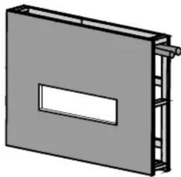
natural_image
3D diagram of a rectangular enclosure with a central opening and vertical supports (no text or symbols)Create the Cavity Install electrical / gas connections, flue system, and fireplace
Finish installation and fit fascia
Section B Section C, D Section F
A3 Product Dimensions
NOT TO BE MISTAKEN FOR CAVITY DIMENSIONS
All dimensions are in mm.
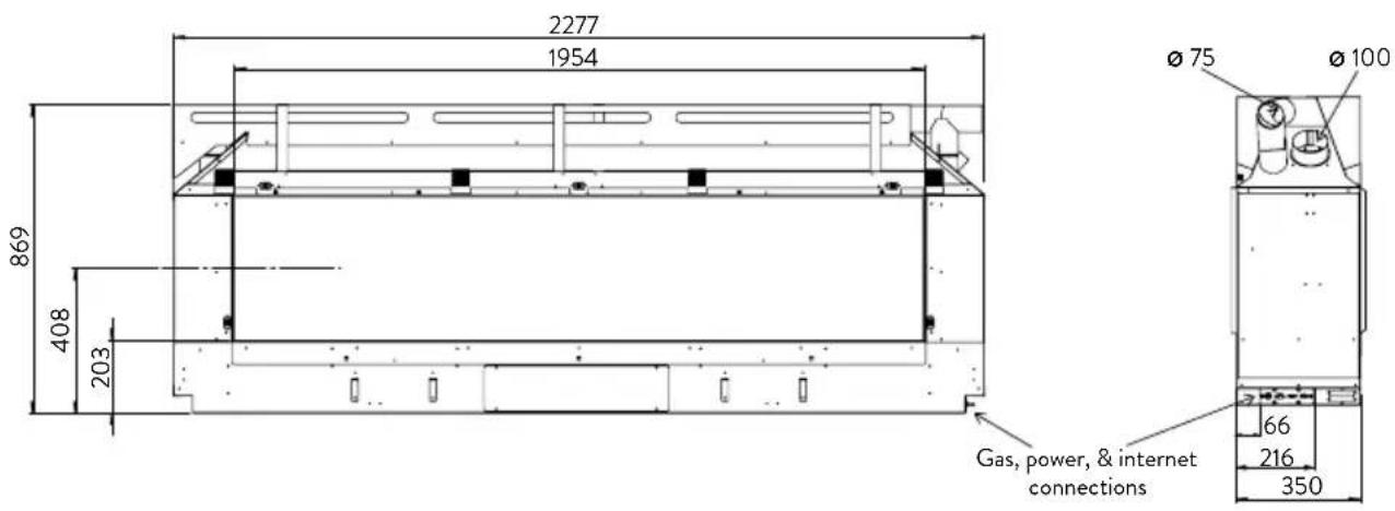
For more detail, view architectural drawings at www.escea.com or www.escea.com.au
B Creating the Cavity
B1 Cavity Shape
The DS1900 is suitable for timber framed cavities.
Most existing masonry cavities will not be suitable.
B2 Designing the Cavity
The following aspects must be considered when designing this installation:
• Appliance physical size
- Single sided or double sided
• Wall finishing and interaction with appliance
- Positioning of appliance in regards to wall lining (depth into wall)
• Use of a fascia - one side or two sides?
- Exhaust termination aspect – horizontal / vertical and flue configuration
- Flue exhaust fan noise - Is there a direct noise path along the flue, especially for short flue runs?
• Exhaust cowl access for maintenance
- Gas pipe layout
• Gas isolation valve / pressure test point position
• Electrical isolation switch
• Home automation network connections - ethernet cable layout
The DS1900 fire is to be installed prior to any wall lining. The wall lining is the very last task to be completed in this installation.
The cavity and wall linings may be constructed from standard timber framing materials and do not need to be non-combustible.
It is not necessary to line the sides or back of the cavity.
Recommended Framing Dimensions

Note: These are minimum cavity framing dimensions and may not achieve a centred fireplace design in all specifications. Please adjust overall cavity size if required.
Note: For masonry installations, clearance will be slightly larger to allow access to the electrical and gas connection points. Please contact the Escea advisory team at aa@escea.com.
B3 Hearth
A hearth is not required. If a hearth is installed below the fire, it must be at least 100mm below the bottom of the glass or be composed entirely of non-combustible materials.
B4 Cavity Base
This appliance MUST be fully supported on its base, over the entire area of the underside of the appliance. The base must also be level and strong enough to support the total product weight, which is approximately 160kg.
The fireplace can be recessed into the ground but must maintain clearances detailed in the diagram (shown right) for any combustible flooring materials.
NOTE: A recessed floor is required to install the fire with the opening less than 200mm above the floor.

B5 Wall Lining
Only after all applicable sections up to section F5 on page 41 have been completed is it permissible to commence with the final wall linings detailed in section F6 on page 42. Wall lining cutout dimensions around the glass must be adhered to.
Please refer to section F6 on page 42 for wall finishing dimensions surrounding glass.
B6 Television & Mantel Clearances Television
The diagram (shown right) shows the recommended minimum clearances for the location of any electrical equipment (such as Plasma TV, LCD TV or home theatre) above a DS Series gas fire. A mantel/recess is not required to comply with our recommendation of TV installation.
NOTE: Dimensions are from the top edge of the glass frame.
NOTE: The television clearance recommendations are to be treated as a suggestion of a suitable installation only. It is the responsibility of the end user to check the installation instructions of their electrical appliances to ensure that the location in relation to the gas fire is suitable. Escea in no way guarantees or takes responsibility that the recommended installation suggestion will be suitable for all electrical or home entertainment appliances.
Mantel
Please refer to the diagram (shown right). Mantels or protruding ledges above the heater must not be installed lower than the dimension shown.
NOTE: Dimensions are from the top edge of the glass frame.

C1 Flue Configuration (If less than 8m flue length is required)
If your flue system is less than 8m long (as shown in diagrams below), then a simple aluminium flexible flue is required. If you wish to install a longer flue run, contact the Escea Advisory Team.
Horizontally Terminated: Utilises the Escea horizontal power flue enclosure kit.
The horizontal offset of the terminal can be any amount up to the total flue length listed below. Please consult with Escea's technical staff if your intended flue configuration falls outside of the bounds of the flue configurations shown below.

NOTE: When flueing above the fire, the pipe must slope towards fire - NOT towards the terminal. Also when flueing below the fire, the pipe must slope towards the terminal - NOT towards the fire.
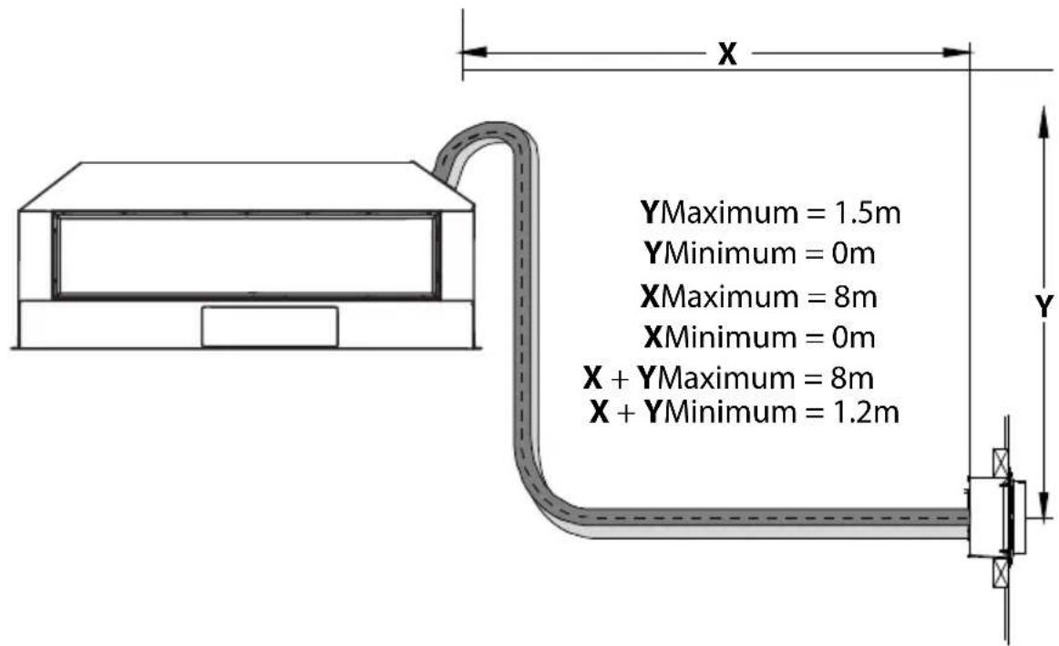
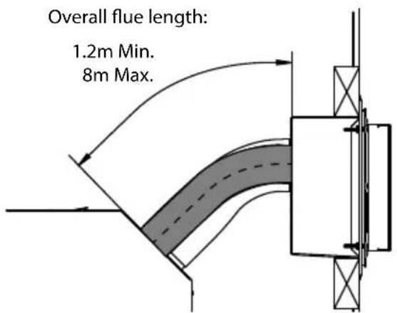
Vertically Terminated: Utilises the Escea universal vertical power flue enclosure kit.

C2 Flue Configuration (If more than 8m flue length is required)
If your flue system is greater than 8m long (up to 40m long), then please contact the Escea Advisory Team at aa@escea.com for further guidelines.
C3 Installing the Horizontal Powerflue Wall Terminal option
The horizontal powerflue wall terminal must be installed in the correct orientation (the small horizontal slot should be at the bottom). This allows for the correct operation of the flue system and prevents the ingress of water.
The horizontal powerflue wall terminal must be weather-tight when installation is complete to prevent damage to the dwelling. It must be installed by a suitably qualified person.

natural_image
Technical line drawing of a cabinet or enclosure assembly with two views, showing internal components and structural details (no text or symbols)Fit the horizontal powerflue wall terminal into the hole and fix in place, making sure the installation is sealed appropriately to prevent the ingress of water from outside the wall cladding. Take notice of the label on the termination which shows the correct orientation of the terminal.
Note: It is the responsibility of the installer to ensure the horizontal powerflue wall terminal is installed to all relevant building codes to ensure weather tightness.
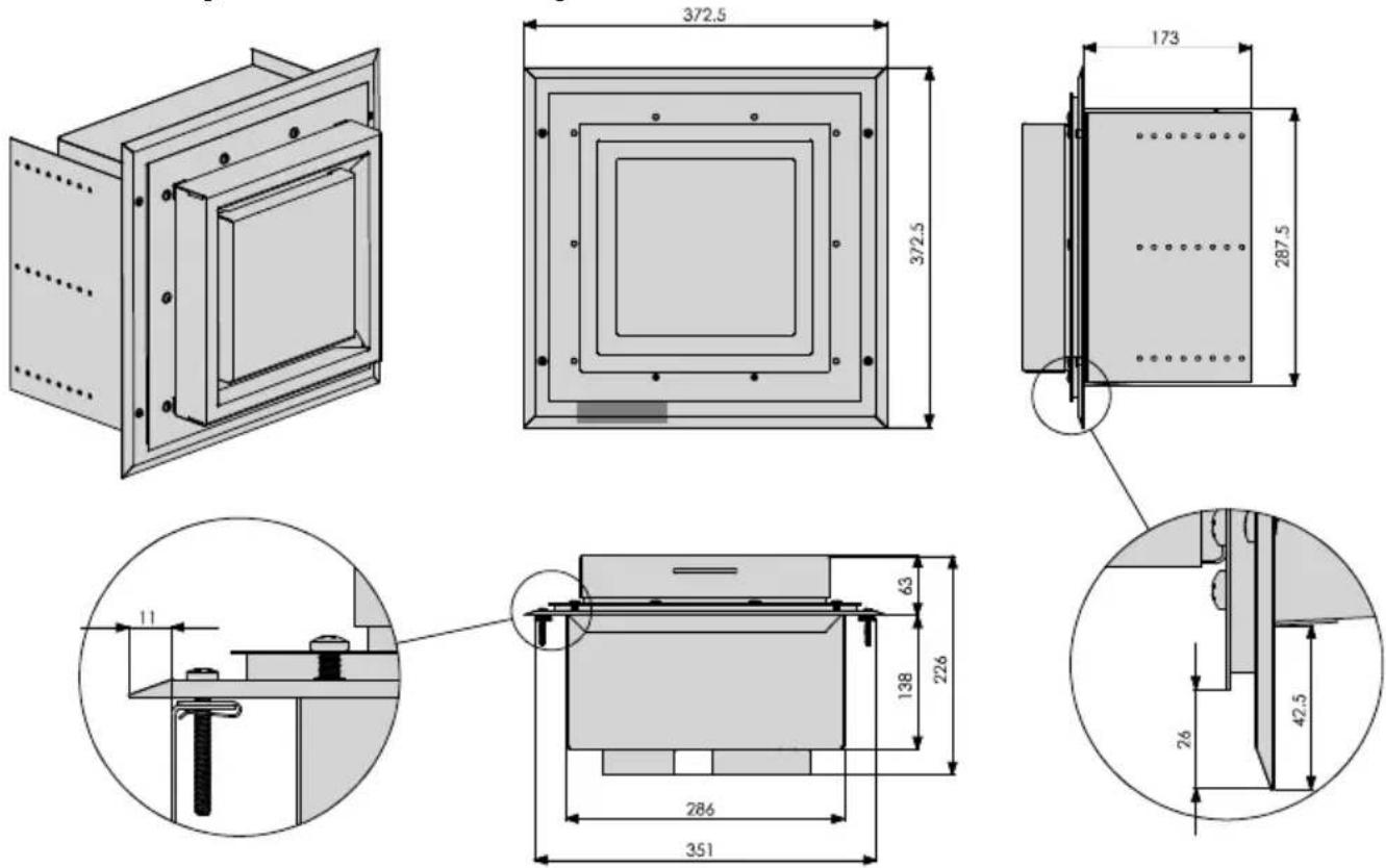
Creating the Hole in the Outside Wall
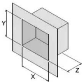
When cutting the hole in the outside wall, be mindful of how the installation of the horizontal powerflue wall terminal will be finished; the installation must be weatherproof.
natural_image
Isometric diagram of a 3D rectangular prism with labeled X, Y, Z axes (no text or symbols on the shapes themselves)Ideal Hole/Cavity Size for Horizontal Powerflue
Without Side Brackets With Side Brackets
X 298mm 360mm
Y 298mm 298mm
Z 175mm Excluding allowance for flue which exits here
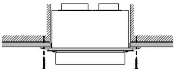
The horizontal powerflue wall terminal can be attached to the wall in two ways:
A) From the front of the terminal:
natural_image
Technical diagram of a mechanical assembly with two components and alignment markers (no text or symbols)B) By attaching the optional wall terminal installation brackets to the sides of the cavity and attaching the horizontal powerflue wall terminal to these, from the front:

natural_image
Pure mechanical assembly diagram showing a central block with flanges and supports (no text or symbols)Attach the ∅100mm and ∅75mm flexible aluminium flues to the spigots on the rear of the horizontal powerflue wall terminal using the hose band clamps supplied. Plug the powerflue electrical cable into the back of the horizontal powerflue wall terminal.
Ensure that the electrical cable is firmly secured to the wall terminal or building to prevent damage or disconnection if pulled.

natural_image
Diagram of a hand connecting two circular components to a wall-mounted device (no text or symbols present)Fit the horizontal powerflue wall terminal into the hole and fix it in place, making sure the installation is sealed appropriately to prevent the ingress of water from outside the wall cladding.
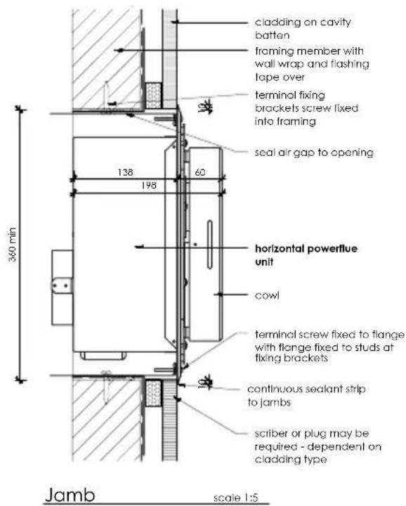
Note: It is the responsibility of the installer to ensure the horizontal powerflue wall terminal is installed to all relevant building codes to ensure weather tightness. This may necessitate the use of appropriate flashing material where appropriate.
IMPORTANT: Ensure that flashings do not restrict the air intake slot around the periphery of the cowl.
How to Flash the Horizontal Powerflue
The following diagrams are excerpts from the Escea architect drawings and are available in full on our website. These diagrams are recommendations, and your installation must comply with any local or national building codes.

C4 Installing the Universal Vertical Powerflue (Internal Install)
Note: For information regarding an external install of the UVP, go to section C5 on page 16.
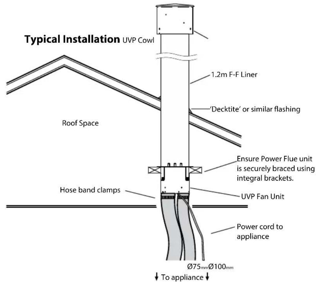
The Universal Vertical Powerflue (UVP) internal configuration is designed to have the fan, mounted within the roof space of the house, and the vertical ∅225mm diameter liner, containing a ∅100mm flexi, penetrate through the roof. The UVP internal conversion kit comes with a 1200mm liner that is specific to the internal installation and must always be used.
Note: The flue setup must comply with either section C1 on page 10 or C2 on page 12.
Use standard methods to flash the roof penetration. The installation must be weatherproof and conform to all local council standards including powered flue termination rules.
Mount the fan mount bracket (1) to the roof framing and strapping using timber ensuring that the flue is rigid and vertical. Ensure that the mounting timber does not obstruct access to the 3xM5 screw threads on the side of the fan unit.
Aim to have the fan enclosure (2) mounted as high as possible, mainly to allow sufficient fall for condensation drainage if the flexi-flue is to run horizontally.
Ensure there is sufficient space below fan enclosure (2) to have access to fit the flexi-flue tubes (3) and allow flowing bends if required.
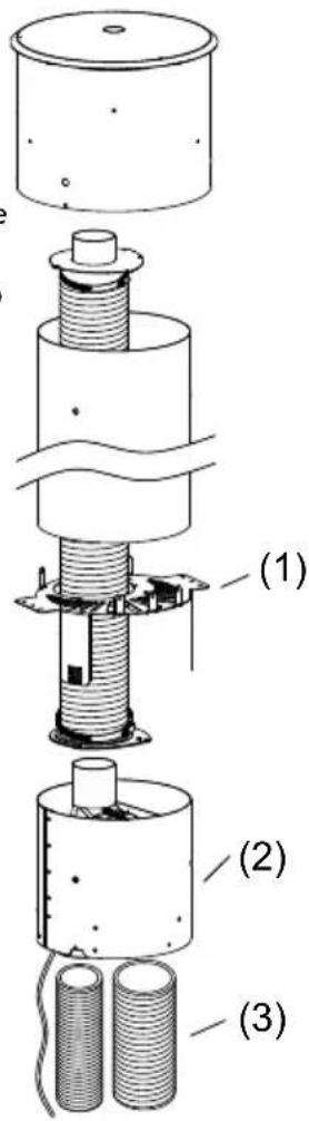
Note: The UVP-Internal and the flexi flue connections must be installed in a location accessible for service or replacement; a service hatch or removable flashing to allow access may be required.
Note: When installing the unit onto a flue liner, ensure the length of flue liner above the roof is the minimum required length. ENSURE the ∅25mm restriction plate is installed on the inlet.

The UVP-Internal kit is intended for use within an accessible roof space or 'chimney' construction. Service access must be provided.
Ensure installation complies with relevant building codes and regulations
C5 Installing an Universal Vertical Powerflue (External Install)
Note: For information regarding an internal install of the UVP, go to section C4 on page 15.
The UVP is designed to have the enclosure containing the fan unit mounted externally.
The cowl surround should be fixed in place as shown.

natural_image
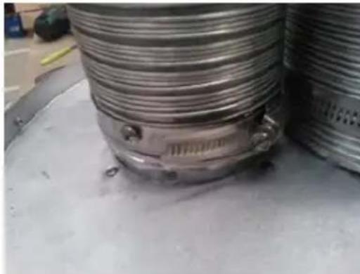
Simple line drawing of a cylindrical object with a flat base and circular top, no text or symbols present.Mount the UVP kit to the top of a chimney flashing plate or penetrate the roof with an optional flue liner accessory and fit the UVP kit over the flue liner, sealing the penetration with a decktite or similar flashing. Ensure the terminal is vertical and rigidly mounted, the flexi flue attached below is fixed to the terminal spigots using the supplied hose clamps. The flexi flue is held in place by drilling 3 holes and screwing 3 self tapping screws evenly around each hose band clamp (as shown in the picture below).
Note: When installing the unit onto a flue liner, ensure the length of flue liner above the roof is the minimum required length. ENSURE the ∅25mm restriction plate is installed on the inlet.
natural_image
Close-up of a metallic cylindrical component with bolts and a metal bracket, mounted on a white surface (no visible text or symbols)C6 Installing in Accordance with Relevant Codes
The location of the horizontal powerflue wall terminal must be installed in accordance with AS/NZS 5601 and any other relevant building codes. If possible, avoid installing the horizontal powerflue wall terminal in areas exposed to high winds and extreme weather.
Some of the minimum clearances for a fan assisted wall terminal are listed below; please refer to AS/NZS 5601 Gas installation standard for full guidance on the design of the flue system. Where possible allow a greater clearance.

| A Below eaves, balconies and other projections 200mm | ||
| B From the floor, above a balcony or other surface 300mm | ||
| C From a return wall or external corner 300mm | ||
| D From a gas meter or regulator vent 1000mm | ||
| E | From electricity meter or fuse box | 500mm |
| F | From a drain pipe or soil stack | 75mm |
| G Horizontally from any building structure or obstruction | 500mm | |
| H From any other flue terminal or combustion air intake | 300mm | |
| J | Horizontally from any moving window, door, non-mechanical air inlet, or any other opening into a building with the exception of sub floor ventilation | 300mm |
| K From a mechanical air inlet or spa blower | 1000mm | |
| L | Vertically below any moving window, door, non-mechanical air inlet, or any other opening into a building with the exception of sub floor ventilation | 300mm |
| N Horizontally from a roof light | 600mm | |
| O Vertically from a roof light | 500mm | |
| Q Vertically from a flat roof | 500mm | |
| R Horizontally from a vertical structure 500mm | ||
| S | Below a roof window | 2000mm |
| T | Above or either side of a roof window | 600mm |
| U From a dormer window | 1500mm | |
| V Above the apex of the roof (see note 1 on following page) | 300mm | |
| W | From an open flue | 1500mm |
Notes:
1) Should the flue not extend past the apex of the roof, the bottom opening of the flue should extend at least 200mm from the roof (or 300mm in regions with heavy snow).
2) The installation of a flue into a carport is not recommended.
3) The flue terminal will get very hot when in use. Precautions should be taken to protect people and animals from injury.
C7 Running the Flue
A 50mm clearance to combustibles must be maintained from the exhaust flue for the first 1.2m of flexi flue from the appliance (see diagram below).
Run the ∅100mm and ∅75mm flexible aluminium hoses from the cavity to the rear of where the horizontal or vertical powerflue terminal will be installed. Allow enough stretch in the flexible aluminium flue to allow it to protrude through the wall/ceiling/roof/flue liner to enable it to be connected to the powerflue terminal. The flue should be expanded at each end in order for the flue to be attached to the fire/powerflue. It is advisable to secure the flexi flue at regular intervals to prevent vibration, movement and sagging. Steel wire or ‘builders strapping’ may be used for this purpose.
Note: The flexible flue is shipped in a 'compressed' form. Extend it to your desired length by stretching.

C8 Running the Powerflue Electrical Cable
Note: The powerflue terminal is powered from the appliance and must be connected to the appliance with the supplied electrical cable only.
Note: Ensure that the appliance power supply is disconnected before making the connection to the terminal
The supplied powerflue electrical cable is 7m long; flue extension kits also include a powerflue electrical cable extension.
Run the powerflue electrical cable from the cavity where the appliance will be installed to the hole in the outside wall. Ensure it is not draped over, or in contact with, the outer shell of the appliance or the flues. The cable must be kept clear from any other possible heat sources, sharp edges, or moisture. Fix it appropriately and allow enough cable to be able to pull both the appliance and the powerflue terminal out from their installed positions.
The powerflue electrical cable connects on the lower right hand side of the fire, as shown below.

If you do not connect the powerflue electrical cable to both the fireplace and the powerflue, this will result in an error when the fireplace is turned on.
Test the fan before continuing with the rest of the installation.
END OF SECTION C
By the end of this section, you should have:
☐ A weather-tight installed powerflue terminal with clearance as specified by AS/NZ5601 ☐ Reasonable access to the terminal for maintenance purposes
☐ Flue attached to the powerflue terminal leading back to the appliance with the correct flue clearances
☐ The electrical cable from the powerflue terminal run back to the appliance cavity in an electrically safe manner
D Installing the Electricity and Gas to the Appliance
D1 Power Supply
While the cavity is being created, consideration must be given to the location of an appropriate power supply. An earthed 230/240 volt mains power connection (typically a standard 3 pin outlet) must be available within 1m of the bottom right of the appliance. This connection must be accessible after the heater has been fully installed so that the appliance can be safely disconnected from the mains power supply prior to servicing.
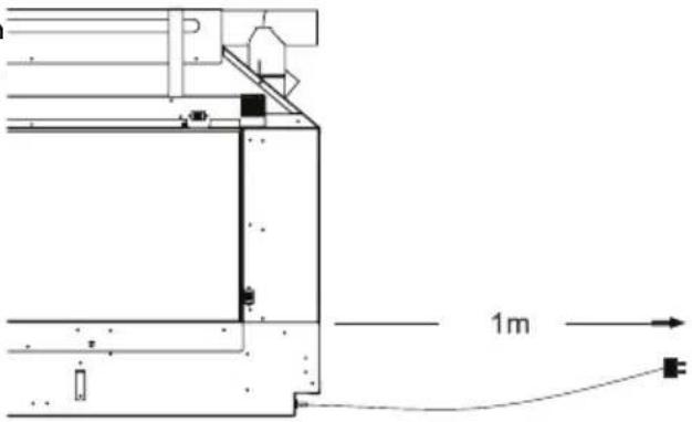
A mains isolation switch (compliant to AS:NZS 5601 Clause 6.2.8) which is accessible from outside the cavity can also be used to disconnect the power.
Regardless of the method used, it MUST ALWAYS be possible to safely isolate the electrical supply to the appliance after it has been fully installed.
This appliance must not be located immediately below a socket outlet. This appliance will draw a maximum of 2 Amps from a 230/240V supply. No additional power supply is required for the power flue.
D2 Network Cable
A 10 metre length of network (ethernet) cable has been supplied. Connect it to the appliance (lower right) and the buildings' modem.

natural_image
Technical line drawing of a mechanical assembly with no visible text or symbolsTwo network cable access points are available: the primary connection is on the bottom of the RH outer face of the appliance for connecting permanently to the buildings' router; the secondary connection point is located where the AUX button is (shown in section E10) for service technicians to access when the main connection method has not been used and has become inaccessible.
If you do not wish to connect the fireplace to the modem, the network/ethernet cable should be run to somewhere accessible by a service technician, such as a cupboard.
D3 Gas Pipe Sizing
Gas pipe should be sized as per the requirements of AS/NZS 5601.1. The pipe sizing must be sufficient to deliver the following volume of gas to the heater with all other gas appliances in the home running at the same time:
Maximum DS1900 Gas Consumption = 49MJ/hr
D4 Gas Pipe Position
The gas connection is inside the appliance and is 12 " male BSP on the lower right of the appliance as shown below. Access is through the silicone grommet circled below on the RH side of the chassis.

Access for connecting the gas supply to the gas connection point (shown in the diagram above) should be through the access hatches located on the front and back of the appliance (the front as shaded in the diagram below).

natural_image
Architectural cross-section diagram of a building facade with structural elements and doorways (no text or labels)Warning: The access hatch must be replaced prior to installing the wall linings!
D5 Gas Isolating Valve
A gas isolating valve must be installed in the gas line as close to the appliance as possible. Fix it in a convenient position to allow it to be closed off quickly and easily during normal operation. Take into consideration access to this valve once the wall linings are on. This will also allow for easier servicing in the future.
END OF SECTION D
By the end of this section, you should have:
☐ An unlined cavity with 230/240V AC supply where the appliance can be plugged into an electrical isolating switch that is accessible once the appliance is installed
☐ A suitably sized gas supply to the right hand side of the appliance with a pressure test point, ready to be connected once installed
☐ Network cable installed, ready for plugging into appliance, regardless of being connected to Internet router/network
E
Installing the Appliance
E1 Connecting the Flue
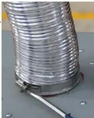
Access the top of the appliance and connect both the inlet flue (∅75mm ID/85mm OD) and the exhaust flue (∅100mm ID/110mm OD) to their respective spigots. Tighten the hose clamps onto the spigots. Ensure the flue connection is air tight. Sealant is not required.
WARNING: The flue connection MUST be secured with the clips provided and tape MUST NOT BE USED. If any of the flue pipe is damaged and integrity compromised then it should not be repaired with tape, it should be replaced.
natural_image
Close-up of a coiled metallic cylindrical component with a tool inserted, mounted on a metal base (no visible text or symbols)E2 Installation
Insert the gas fire into the cavity and fix the appliance down in the correct position using the brackets on each end of the appliance. It is a requirement that this appliance be securely fastened at the base.
Ensure that the fire is seismically restrained in a manner appropriate to the installation location.
E3 Removing (and Replacing) the Glass
Remove the glass by unscrewing the six 1/4 turn fasteners located at the top of the glass (circled below) and remove the bracket (shown below shaded grey). Allow the glass to lean towards you and carefully lift it out. Place the glass carefully aside. Note that the fiberglass tape around the glass can mark carpet and furnishings.

natural_image
Pure mechanical diagram showing a lever with a screwdriver inserted, no text or symbols presentNOTE: When replacing the glass, check the channel that the glass sits in for debris that may be sitting on top of the fiberglass tape. Remove any debris prior to placing the glass. If you feel resistance when leaning the glass towards the fireplace, remove it and double check for debris in the glass channel.
WARNING: Trying to place the glass with debris in the glass channel may result in the glass breaking.
E4 Remove the Infill & Burners
Remove the eight screws shown in the diagram below. Lift one end of the infill up into the top corner of the firebox and then out towards you, taking care not to scratch the firebox paint and reflective panels. Remove the outer burners first by sliding them away from the centre of the fireplace, followed by the centre burner, which slides out to the left.

natural_image
Pure schematic diagram of a mechanical or fluidic system with directional arrows and circular components, no text or symbols present.E5 Single Sided Front to Back Conversion (only for single sided fires)
-
Follow sections E3 on page 24, E4 on page 25, and E9 on page 34 to remove the glass, infill, burners, and bottom trim bracket.
-
On the inside of the firebox, slightly loosen the firebox liner bracket (shaded in the diagram below) by loosening—not removing—the 3 screws (circled in the diagram below, quantity may differ with model).
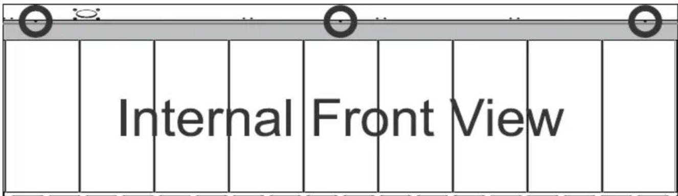
- Carefully swing the lower edge of each firebox liner towards you and pull down to release each panel (shaded in the diagram below). It may be necessary to slide the firebox liner to the side first. Remove the firebox liner bracket and replace the screws.

- Move to the back of the fire for the following steps. Remove the screws (circled in the diagram below) in the back panel of the appliance. Remove the back panel.

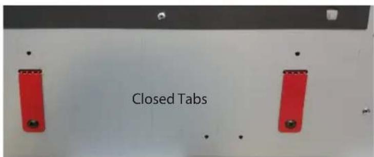
- On the back of the appliance remove one screw from each of the four red tabs and set each pair of tabs from 'open position' to 'close position' (shown below). This is necessary to change the airflow path of the fire for a double sided conversion.

flowchart
graph TD
    A["① Remove the screw"] --> B["② Bend tab down to horizontal position"]
    B --> C["③ Push tab in to the next perforated section"]
    C --> D["④ Bend tab down at new perforated mark and secure"]
    D --> E["⑤ Replace the screw"]
    E --> F["⑤ Please Take Extra Care on this STEP"]

- Remove the 6 screws in the chassis (shown circled below) and remove the side brackets (shown shaded below) by pulling them in towards the centre of the fire.

- Remove the bottom air deflector (shown shaded below).

- Now remove the top bracket by unscrewing the 1/4 turn fasteners (circled below) and allow the panel to lean forward so you may lift the panel out.

-
Remove the bottom trim by pulling hard to release it from the appliance and taking care not to scratch the side trims (shown below).
-
Remove the two side trims. These are fixed top and bottom wit low profile self tapper screws (see below).

natural_image
Diagram of a window with a hanging object and directional arrows indicating movement or force (no text or symbols present)- Remove the top trim bracket from the front by unscrewing the black machine screws (circled below).

natural_image
Technical line drawing of a structural beam with supports and mounting points (no text or symbols)- Relocate the diagnostic bracket to the opposite side of the appliance by carefully removing the middle screw and feeding it through to the opposite side of the fire (as shown in the diagram below). Note: this step must be completed after preparing the other side of the appliance for either a LH to RH conversion.

- Using the diagram from step 5, change the position of the four tabs on the original front side from closed to open. Ensure those on what is now the front are in closed position.
Note: After any conversion AIRFLOW MUST NEVER be coming up the glass from the bottom, it must ALWAYS EXITING FROM the top of the glass.
- Replace all the parts removed in steps 2-11 to the front of the appliance by reversing the procedure documented above.
- Reinstall the burners and infill by reversing the steps outlined in section E4 on page 25.
- Install the fuelbed media as per section F on page 36. Finish the conversion by installing both pieces of glass and both bottom trim brackets.
E6 Gas Type Conversion
THIS APPLIANCE IS CONFIGURED TO OPERATE ON A NG, ULPG, or PROPANE. If a gas type conversion is required, please contact Escea to request the necessary parts. Follow the steps on the following pages to change from NG to ULPG/Propane or vice versa.
WARNING: The regulator that is supplied with the fire MUST NOT BE REMOVED.
Removal of the regulator, or replacing it with one not intended for use with this Escea fire, will void the limited appliance warranty.
Turn off power and gas first.
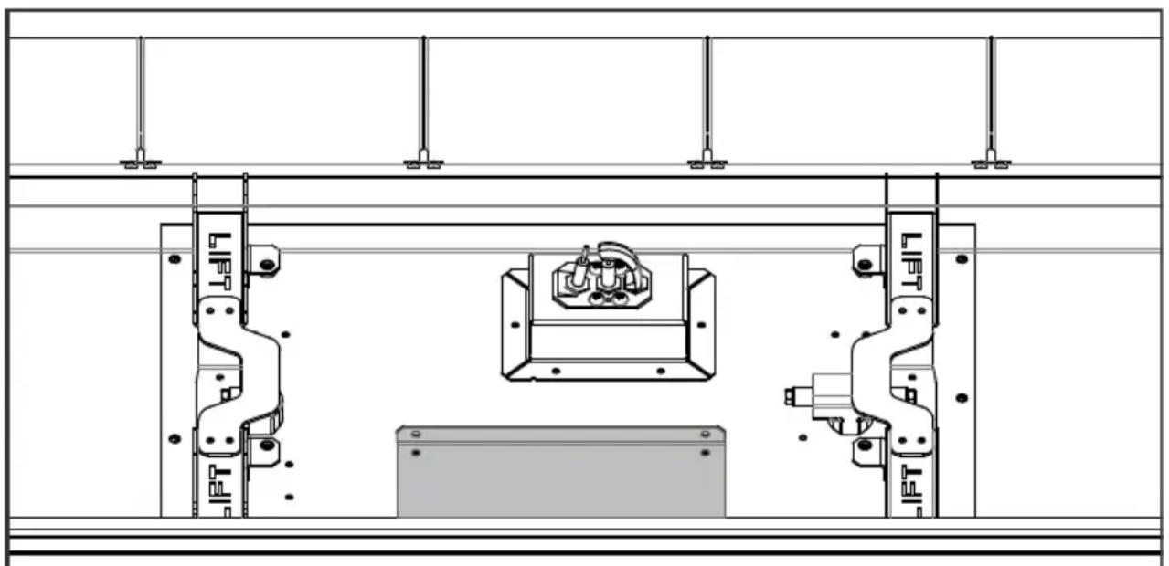
Step 1: Remove the screws on the control tray hatch (shown shaded in the diagram below).
natural_image
Technical line drawing of a mechanical assembly with two vertical supports and internal components (no text or symbols)Remove the hatch to access the regulator and modulating valve below.
Step 2: Change the three main burner jets with the jets supplied in kitset (see tables on next pages).
Step 3: Replace the pilot jet (see tables below). Note: Ensure the pilot jet is joined up to the olive before inserting the jet into the pilot assembly (as shown below).
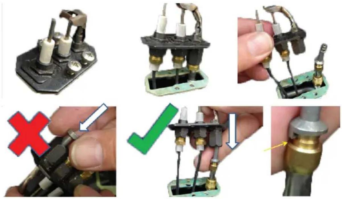
Step 4: Screw out the nylon adjuster screw inside the regulator to remove the existing spring. Replace the spring with the coloured spring supplied in the conversion kit and reassemble the regulator.
Step 5: Stick the new gas type label supplied in the kitset on the underside of the tray hatch. Ensure the serial number and date of manufacture are still visible. Write your name, company (if appropriate) and date of conversion on the new label with permanent marker.
Step 6: Replace the hatch (removed in step 1). Take care not to over tighten screws.
Step 7: The burner tubes on the underside of all burners have convertible aeration collars. Ensure the aeration collars on all burners are correctly fitted on each burner tube.

natural_image
Technical line drawing of a cylindrical mechanical component with two protruding slots (no text or symbols)| Burner Jets Burner Collars | |||||
| Middle Burner | Side Burners Pilot | Middle Burner Side Burners | |||
| Natural Gas | ∅2.1mm ∅1 | 95mm #37 Fully | Closed | Fully Closed | |
| ULPG | ∅1.4mm | ∅1.1mm | #27 | Spacer | 2 x ∅6mm |
| Propane | ∅1.4mm | ∅1.1mm | #27 | 2 x ∅12mm | 2 x ∅4mm |
Step 8: Adjusting the electronic controller for gas type
Ensuring the gas is still OFF, Turn the power ON. Insert "AA" size batteries into the remote control. You should now see the time on the remote display showing 0:00.
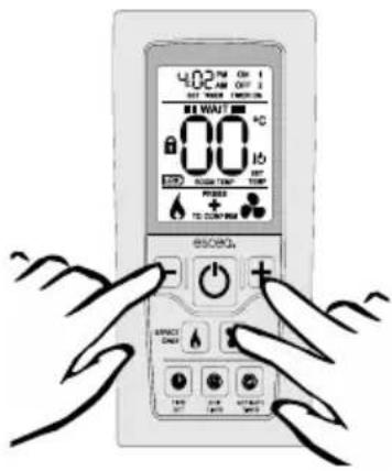
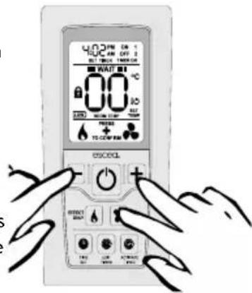
Press the MINUS, PLUS and FAN BOOST buttons simultaneously (as shown right) until the characters "03" light up on the display. Release the buttons and the remote will count down and display "GO". The screen will then display all characters. This will put the remote into test mode and the two big temperature digits should begin counting from 0 to 99 repeatedly.

Now hold down the 'EDIT TIMER' and 'ACTIVATE TIMER' buttons simultaneously; the remote display will show the current configuration of either 'NG' for Natural Gas or 'LP' for ULPG/Propane. To change this configuration, hold down the 'EDIT TIMER' and 'ACTIVATE TIMER' buttons simultaneously for 5 seconds. This will now have toggled between gas types.
Once you are have chosen the correct gas mode, simply press the “power button once to exit this diagnostics mode.
E7 Operating the Appliance
Turn on the fire by pressing the “💡” power button on the remote. Within a few seconds the appliance will begin its startup sequence with a 15 second purge of the flue fan. After the purge it will attempt ignition. It may take a few attempts to light the first time due to air in the gas line. You may wish to purge the gas line at the valve by bleeding the first test point. This requires a small blade screwdriver.
Once the fire has lit the pilot and main burner you will be able to measure the operating pressure. Set the remote temperature to 40deg by pressing the "+" button and ensure the remote is kept in a cool environment. This will allow maximum gas flow into the appliance.
Ensure all other gas appliances within the house are also operating at maximum.
If the operating pressure does not read within 5% of the table (shown below) then remove the cap from the gas pressure regulator within the appliance and adjust the threaded spring stop. Press the button again to shut down the fire.
E8 Checking the Gas Operating Pressure
Note: Ensure the thermostat control within the remote does not cause the flame to modulate down by increasing the set temperature and keeping the remote in a cool environment.
Turn on the gas. Turn the power on. Check the inlet pressure upstream of the appliance using the test point installed earlier. Note: The regulator that is supplied with the fire MUST NOT BE REMOVED. Removal of the regulator, or replacing it with one not intended for use with an Escea fire, will void the limited appliance warranty and may be dangerous.

The gas valve (shown right) has manometer test points at A, C, and D. Ignore B.
| Gas Pressure Table - DS1900 Gas Type | |||
| Natural Gas Propane (AUS) | ULPG (NZ) | ||
| Minimum Inlet Pressure - Pre-Regulator 1.13 kPa | 2.75 kPa | 2.75 kPa | |
| Maximum Inlet Pressure - Pre-Regulator 5.0 kPa | 5.0 kPa | 5.0 kPa | |
| Operating pressure - Post-Regulator (Point C) | 1.0 kPa | 2.3 kPa | 2.3 kPa |
| Operating Pressure when on high - (Point A or D) | 0.82 kPa ±5% | 1.79 kPa ±5% | 1.79 kPa ±5% |
| Operating Pressure when on low - (Point A or D) | 0.43 kPa ±5% | 0.88 kPa ±5% | 0.88 kPa ±5% |
Remove the small access hatch found on top of the engine.
Loosen test point C (shown in the first diagram of this section) and attach a manometer tube in preparation for measuring the operating pressure—post regulator.
Turn the fire on high and adjust the operating pressure at the regulator (shaded grey in the diagram below)

natural_image
Technical line drawing of mechanical components and housing (no text or symbols)Once the operating pressure—post regulator—is set, check the operating pressure at test point A or D (shown in the first diagram of this section).
Changing the Operating Pressure from the Remote
The following instructions must only be undertaken by a suitably approved person. Any tampering by an unauthorised person will void the product's warranty and may result in a dangerous condition.
While the remote is in its "OFF" mode with only the time showing on the display, press the MINUS, PLUS and FAN BOOST buttons simultaneously (as shown right) until the characters "03" light up on the display. Release the buttons and the remote will count down and display "GO". The screen will then display all characters and should be reading 00. This will put the remote into test mode.
Whilst in test mode: press and hold the "ACTIVATE TIMER" and "FAN BOOST" buttons for 4 seconds to access the gas valve settings. The appliance will automatically turn on while in this mode.
WAIT. Allow the appliance to fully light all burners before continuing.
The high setting for the currently set gas type is displayed first (indicated in the clock segments at the top - see ! right). Pressing the plus or minus keys will change the setting up or down respectively, which will change the gas pressure measured at point A or D. The large digits will blink rapidly after the setting is made until the verification is received from the fire.
Note: The numbers displayed on the remote should only be used to achieve the correct pressure. The numbers by themselves do not represent anything and should not be relied upon.
Toggling to the low setting is done by pressing the 'EFFECT ONLY' button (indicated in the clock segments at the top and by the 'EFFECT ONLY' icon at the bottom). Settings are made with the PLUS and MINUS buttons as above. Exit this mode by pressing the on/off button.


*The numbers shown above are not targets
Changing from Celsius to Fahrenheit
By default Escea gas fires are set to Celsius. To change from Celsius to Fahrenheit or back, you need to follow the steps below to make the adjustment to your Escea remote.
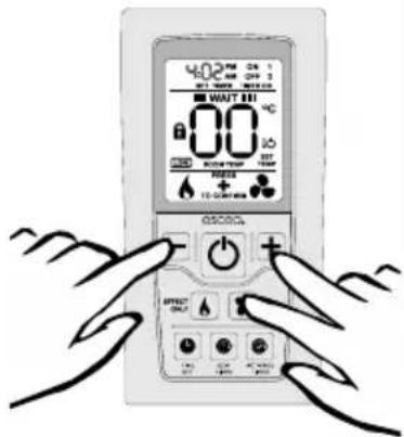
Step1: While the remote is in its "OFF" mode with only the time showing on the display, press the MINUS (3), PLUS (7) and FAN BOOST (8) buttons simultaneously (as shown below right) until the characters "03" light up on the display. Release the buttons and the remote will count down and display "GO". The screen will then display all characters. This will put the remote into test mode and the two big temperature digits should begin counting from 0 to 99 repeatedly.
Step 2: Press the FAN BOOST button (7) and see the C or F flash with the chosen degree mode.
E9 Auxiliary On/Off button
The auxiliary on/off button is used to turn the fireplace on without the remote control and for “teaching” the fireplace to listen for new remote controls. For information on teaching a new remote control, see section S6 on page 52 of the service manual at the end of this document.
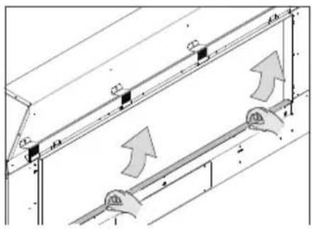
To access the auxiliary on/off button, remove the bottom trim bracket by lifting the bracket upwards (as shown in the diagram below).
natural_image
Technical diagram of a structural beam with supports and directional arrows indicating motion (no text or symbols)The AUX button location can be seen in the diagram below.

E10 Home Automation Setup
Escea D-Series fireplaces have a simple interface for connection to a home automation system. This allows the fireplace to be woken up, started, and then shut down. The “Close to Wake” connection (shown below) is essentially taking one of the 3.3 volt DC pins on the fireplace micro-controller and shorting it to ground.
In order to isolate the fireplace from the automation system, a relay needs to be used (as shown). This allows you to keep the fireplace's 3.3V supply isolated.
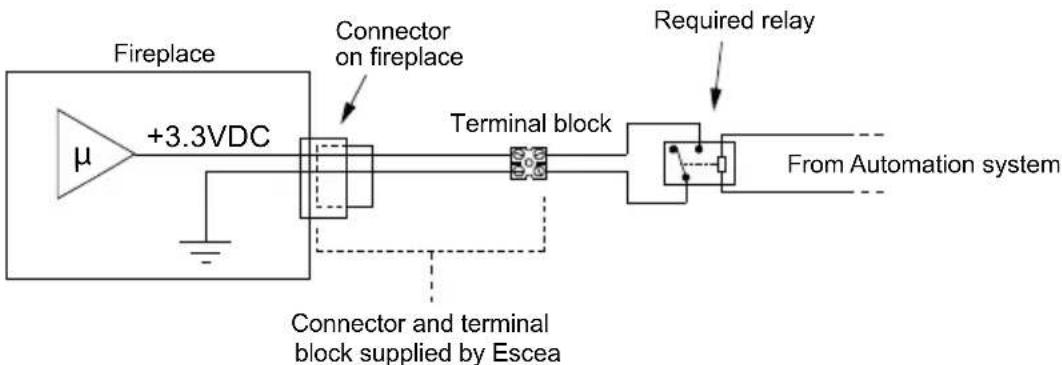
flowchart
graph LR
    A["μ"] --> B["+3.3VDC"]
    B --> C["Connector on fireplace"]
    C --> D["Terminal block"]
    D --> E["Required relay"]
    E --> F["From Automation system"]
    G["Connector and terminal block supplied by Escea"] -.-> D
The home automation connection can be found in your fireplace accessory pack (shown to the right).
This connects to the fireplace via the lower RH outside panel of the fireplace, next to the primary network cable access point, as shown in section D2 on page 21.
Home Automation Operation
Relay closed
The fireplace will start in a medium setting until the remote control talks to the fireplace and picks up the 'ON' signal (which can take up to 4 minutes). Once the remote has communicated with the fireplace it will turn on and begin operating thermostatically. The remote will use whatever temperature the user has previously set and cannot be altered by the home automation system. The fireplace will continue to operate while the relay is closed.
Note: If the fireplace cannot communicate with the remote controller within 10 minutes of the relay contact closure then the fireplace will shut down and return to standby. The remote controller is required to be operating within range of the fireplace for its safe operation.
Relay open
If the fireplace is operating with a closed relay then, upon opening the relay contacts, the fireplace will shut down and return the remote controller to its standby mode when it next updates (which can take up to 4 minutes). While the relay is open the fireplace will be in standby mode and available for manual operation by the user.
END OF SECTION E
By the end of this section, you should have:
☐ The appliance installed in the cavity
☐ Check that red tabs are in the correct position
☐ The appliance fixed to the cavity base and wall lining
☐ The appliance plugged into a mains electricity supply
☐ The appliance gas supply attached and pressure tested with all other gas appliances running
F
Finishing the Installation
F1 Coal or Crystalight Fuelbed Installation
For the coal fuelbed only, begin by installing the three coal retainers, as shown below. They are installed by placing them on top of the infill and fixing them in place with the screws provided.

natural_image
Isometric technical drawing of a structural beam with internal channels and supports (no text or symbols)If using the crystalight or coal fuel beds, place all the crystalight/coal pieces in a single layer atop the burners and fuelbed tray. Cover the entire area except for the pilot shield, ensuring coverage right up to the edges of the firebox or glass.
Do not heap or mound any fuelbed.
F2 Log and Woodland Log Fuelbed Retainer Setup
When setting up a log or woodland log fuel bed, you must have the correct retainers present before assembling the fuel bed. The correct retainers are supplied with the fuel bed packaging. First remove the infill by following section E4 on page 25. Place the infill upside down with the hole for the pilot on the side opposite to you; this is the back. On your retainers you will see a series of letters that determine where the retainers will attach to the infill.
Woodland Retainers
Remove all the retainer brackets from the flat sheet (see below). When reading the text on each individual retainer, fold all the tabs 90° away from yourself.

Looking at the underside of the infill, place the retainers as shown below and fix these in place with the screws provided. On completion, you can now re-install the infill, fuelbed, and glass to finish the replacement.
NOTE: Screws to be fitted from the top side.

Log Retainers
Remove all the retainer brackets from the flat sheet (see right). When reading the text on each individual retainer, fold all the tabs 90° away from yourself.
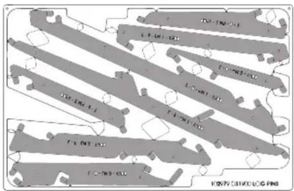
Looking at the underside of the infill, place the retainers as shown below and fix these in place with the screws provided. On completion, you can now re-install the infill, fuelbed and glass to finish the replacement.
NOTE: Screws to be fitted from the top side.

For Logs Only: the final log retainers are placed on TOP of the infill and burners to support the end log (number 2 from index). This part comes in flat form and is to be folded as per the image below.

natural_image
Two identical 3D mechanical bracket assemblies shown in isometric view, no text or symbols present.They are then installed on both outer sides of the infill and are fixed in place by 1 screw as below.

natural_image
Architectural site plan showing structural layout with no visible text or symbolsF3 Log Fuelbed Installation
Log Index

Use the index above as a guide for selecting the correct logs. Place the flakes in a single layer evenly after the logs have been located correctly (excess flakes should NOT be added if one even layer has been achieved). The flakes must not cover the pilot or pilot guard.
Note: Improper positioning of any fuelbed media may create carbon build-up and will alter the unit's performance. Malfunctions due to improper fuel media placement will not be covered under warranty.
Log Setup DS1900

F4 Woodland Fuelbed Installation Woodland Log Index

Use the index above as a guide for selecting the correct logs. Place the flakes in a single layer evenly after the logs have been located correctly (excess flakes should NOT be added if one even layer has been achieved). The flakes must not cover the pilot or pilot guard
Note: Improper positioning of any fuelbed media may create carbon build-up and will alter the unit's performance. Malfunctions due to improper fuel media placement will not be covered under warranty.
An abnormal flame pattern will look long and stringy; it may cause soot to build up inside the firebox.

natural_image
Silhouette of flame-like patterns on black background with a circular checkmark in the corner (no text or symbols)
natural_image
Silhouette of flame-like structures against a black background, with a circled 'X' symbol in the corner (no text or symbols on the flame itself)An abnormal flame pattern will likely be the result of incorrect settings (jet size, burner aeration collar). Check that these are correct before proceeding. If an abnormal flame pattern is still present, please contact Escea.
It is the responsibility of the installer to ensure a correct flame pattern.
F6 Wall Linings
The final wall lining can only be commenced after all previous applicable sections have been completed. The appliance must be installed prior to and behind the finished wall surface. Allow clearance for any plasterboard, tiles, or other finishing materials that may be intended for the finished wall surface. The wall board that lines the outside of the opening can be normal plasterboard and does not need to be non-combustible. The plasterboard must protrude beyond the framework as shown in the following diagram.
Note: The final wall lining must not encroach within the specified dimensions in this section. These dimensions indicate the opening required in the wall lining. Encroaching on the minimum cut out dimension may inhibit the future serviceability of the fire.
The glass viewing area of the fire is bordered by a black metal trim. This acts as a junction between any wall linings and the viewing area. It allows for the wall linings to be up to 14mm in depth. Combustible wall linings must not exceed this dimension and protrude past the black trim. Failure to follow these instructions may risk damage to the adjacent wall lining.
Note: The wall lining directly above the appliance will get warm and hence may discolour paint finishes that are susceptible to temperature damage. The heat may also distort vinyl wall coverings. For durability of finishes and surfaces you should contact the relevant manufacturer for their specification and avoid materials that are not suitable for use above a fireplace. See section A2 on page 6 for more detail).
The wall lining can be fixed to the gib fixing bracket (shaded below). There are four areas on the bracket (circled below) that can be used for fixing screws.

natural_image
Technical line drawing of a mechanical assembly with mounting brackets and mounting holes (no text or symbols)Frameless or Linear Trim Wall Linings
If not using a fascia, ensure the edge of the wall lining is finished in a tidy manner (for a nice Gib finish we recommend Gib Rondo stopping bead). For 10mm-20mm wall linings, an optional “Linear Trim” can be used to cover any unwanted exposed wall lining and/or act as a slimline fascia. Please note that a 6mm (+/-2mm) gap between the top gib trim and the bottom of the gib is required for either frameless or linear trim finishes.

NOTE: a 20mm or less wall lining must be used when installing a DS Series fireplace without a fascia. For wall linings with a total thickness of 10mm or larger, a “Linear Trim” may be purchased to cover any exposed wall lining. A 10mm wall lining is recommended for ease of installation.
Bevelled Lite Fascia
If using a Bevelled Lite fascia, cutouts will be required in the finished plaster board to allow for the fascia securing pins to attach to the appliance.
NOTE: Do not glue the fascia to wall cladding, do not fit cladding around the fascia that prevents it from being removed, do not run the fire without the fascia properly attached, the fascia id designed to be easily removed for future servicing.
NOTE: A 13mm wall lining must be used when installing a DS fireplace with a Bevelled Lite fascia; this is the maximum distance the Bevelled Lite fascia can sit off the front face of the fire.
F7 Fitting the Linear Trim
To install the Linear Trim onto the DS Series, slide the bottom of the trim along the gib trim and push it in flush with the wall cladding. It should slide in on three sides and fit by friction just inside the existing black reveal - the top should sit just above the black reveal.
NOTE: If the friction fit is loose, please use the provided fiber tape along the bottom edge of the linear trim to tighten the fit.

natural_image
Technical line drawing of a mechanical assembly with mounting brackets and a cylindrical component (no text or symbols)F8 Fitting the Bevelled Lite Fascia
To avoid scratches to the fascia panels of this heater, they must be fitted at the conclusion of the installation process, after wall linings are in place.
NOTE: Never rub the fascia.
Step 1: Ensure the plastic spacer is placed on the thread of the studs.
Step 2: Screw and tighten the 4 studs with spacers onto the back of the fascia.
Step 3: Rivet the 4 spring clips onto the bracket on top of chassis of the appliance.
Step 4: After the 13mm thick wall has been finished, the fascia clips onto the appliance.

natural_image
Four-panel photo showing hands installing or adjusting a mechanical component in different views (no visible text or symbols)F9 Locating Wall Mount Cradle for Wireless Control
The appliance's remote contains the thermostat that will sense and communicate the room temperature back to the heater via radio frequency.
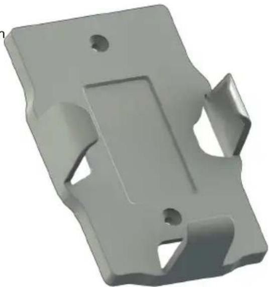
A wall mount cradle has been provided for the wireless control and, where possible, the control should be housed in this cradle.
The location of this cradle should be decided by taking the following factors into account:
☐ Simple and convenient access for the user
□ Away from air flow and drafts through the room
☐ The parts of the room that people are likely to spend time
□ Away from direct sun light
☐ A suitable distance away from the heater
□ Ideally 1.2m to 1.5m from the floor
The radio frequency signal will go through some walls but for best results Escea suggest that the cradle position is less than 10 metres away from the heater.
The best height to locate the cradle off the ground is about chest height. This gives a good average room temperature and easy access for the user.
natural_image
3D rendered image of a gray plastic mechanical bracket with cutouts and mounting holes (no text or symbols)Please ensure that cradle is screwed firmly onto the wall using the screws provided.
F10 Operating the Appliance
If you haven't done so already, insert the supplied "AA" size batteries, being careful of the polarity. "0:00" should now be showing on the remote display.
To turn the fire on, press the 'POWER' button once; within a few seconds the appliance will begin its startup sequence.
NOTE: The appliance begins its startup with a 15 second pre-start purge, where the combustion fan runs on its own to clear the firebox before it tries to ignite. During the pre-purge the remote will alternately show the remotes “set” temperature and a rotating segment indicator to show that the fire is in start up mode and will try to ignite.
When the appliance has lit, set the room temperature by pressing the 'PLUS' or 'MINUS' buttons repeatedly until the display is showing the desired temperature. The remote will then revert back to the 'current' room temperature 30 seconds after making the change.
Run the appliance on full for an hour with the windows and doors open in the dwelling. This will ensure any initial smells have the chance to dissipate.
The appliance is turned off by pressing the ‘POWER’ button once more. The remote will display the time only.
Run the appliance again and check the operation of the thermostat by increasing and decreasing the set temperature. Check that the Effect Only and Fan Boost functions work correctly.
For further operation instructions please refer to the User Guide.
F11 Normal Operating Sounds and Smells
Note: Each time the fire is lit from cold the glass may fog up with condensation. This is normal and the condensation will disappear within a few minutes once the glass heats up.
Sounds
It is possible that you will hear some sounds from your gas appliance. This is perfectly normal due to the fact that various types of materials are used within your appliance. Listed below are some examples. These are all normal operating sounds and should not be considered as defects in your appliance.
Fan:
Escea gas appliances use electric fans to push heated air into the room. It is not unusual for the fan to make a “whirring” sound when ON. This sound will increase or decrease in volume depending on the speed setting of your fan.
Gas Control Valve:
As the gas control valves turn ON and OFF, a dull clicking sound may be audible. This is the normal operation of a valve. When the fire is switched off after being run for a while, there may be popping and fluttering noises as the residual gas in the burners burns away. These are normal and are no cause for concern.
Unit Body/Firebox:
Different types and thicknesses of steel will expand and contract at different rates resulting in some “cracking” and “ticking” sounds being heard throughout the heating and cool down processes.
Smells
The first few times the unit is operated, the unit may release an odour and the flames will appear orange due to: the curing of the paint, the burning off of the starch in the gas logs, and the oils in the metal. This is a temporary curing process which will disappear with use.
A deposit on the inside of the glass, caused by the starch in the logs, may appear as a build up after several uses. If this film is not removed, it will bake on and may become difficult to remove. When the glass is cold, remove it (see section E5) and clean the inside with a non-abrasive cleaner.
DO NOT ATTEMPT TO CLEAN THE GLASS WHILE IT IS HOT.
UNDER NORMAL USE NEVER OPERATE THE UNIT WITH THE GLASS REMOVED.
Go through the following checklist to ensure you have installed the appliance correctly
☐ Correctly sized cavity to suit your fascia and flue configuration
☐ Correct clearances to combustibles
☐ An electrical isolating switch to the appliance, accessible after finished installation
☐ Correctly sized gas supply with a pressure test point, ensuring adequate supply with all other gas appliances in the dwelling running
Gas type conversion process carried out if required
☐ A weather-tight installed horizontal or vertical powerflue terminal with clearance as specified by AS/NZ5601.1
☐ If chosen, reasonable access to the outside face of the horizontal powerflue wall terminal for maintenance purposes and flue attached to the rear of the horizontal powerflue wall terminal leading back to the appliance (or similar for vertical powerflue terminals)
☐ The electrical cable from the powerflue terminal attached correctly and run back to the appliance cavity in an electrically safe manner
☐ The appliance fixed to the cavity base
☐ The appliance plugged into a mains electricity supply
☐ All gas joints and pressure points leak tested with suitable leak detection solution and drop tests completed on gas pipework
☐ Fuel bed correctly installed
□ Glass correctly fitted
□ A fitted fascia
☐ Operated the fire and verified that it lights reliably and safely
☐ Appliance functions checked, including thermostat operation, Effect Only, and Fan Boost
☐ Data label marked up with correct gas type and dated by installer if converted during installation
Home-owner shown how to operate the appliance correctly
☐ Warranty card filled in with installer details and appliance serial number
☐ User Guide made available for end user
☐ Plumbing Industry Commission Compliance Certificate given to end user
IMPORTANT:
• This appliance must be serviced every 12 months.
- Any service operation should be carried out only by a suitably qualified and trained person.
- Gas and electricity supply MUST be isolated before any service operation is carried out on this appliance.
- This manual should be left with the appliance.
- Only use Escea approved spare parts.
- Spare parts are available from an Escea Distributor or Retailer
• DO NOT MODIFY THIS APPLIANCE.
S1 Annual service procedure
☐ Isolate power and gas supply to fire.
☐ Remove front glass and clean inside of glass.
☐ Remove fuel bed and brush off any soot.
☐ Clean electrode and pilot hood of any carbon build up and ensure correct gaps between electrode and pilot hood
☐ Remove burners and blow compressed air through the burner ports.
☐ Remove jets and clean injector hole with solvent.
☐ Vacuum any dust from the cavity that houses the fan and from the underside of the fire box around the valve and solenoids.
☐ Test all joints for gas tightness.
☐ Reassemble heater and check that operating pressure is correct.
☐ Check glass sealing tape and replace if necessary.
☐ Check to make sure that flue system is intact and not in any way blocked.
☐ Trial heater with several start/stop cycles. Trial fan-boost, Effect Only, and thermostat modes to ensure that all modes function correctly.
To access the product data plate, first remove the fireplace glass, any fuelbed media, the burners, and the firebox base. The data plate is located underneath the controls tray (step 1 of section E6).
S2 Error Codes
This gas fire has been designed to show error codes to help explain and identify any fault situation that occurs. These codes will appear on the wireless remote control in the form of a large letter “E” with a number beside it. Codes can normally be reset by turning the heater off then on again at the wall.
The following table shows what each code means and possible ways to rectify the situation. In the case of persistent or repeated shutdown errors, action must be taken immediately to find and repair the fault.
Note: An error code may not signify a fault/warranty issue; depending on the error code, it may signify that the remote batteries are dead or the LPG cylinder is empty. Refer to the section below and contact Escea if needed.
Error Code Suggested action

Electronics Over Temp
The electronics have gone over temperature.
- Check for excess lint and dust build-up on the PCB/Controller.
- Check that fascia panels are installed correctly as incorrect installation may result in restricted air flow.
- Ensure correct gaps are present around glass.
- Room air fans may be slowed or stalled. Remove firebox, check that fans are plugged in, clean, and free turning.
Note: This error has a permanent lock out and will require the unit to be reset after the initial error (turning the power to the fire off "at the wall" then on again after a few seconds).

Flame Failure or Power Flue trip
The fire has tried to light three times and failed.
- Check gas supply and check other gas appliances to see if they are affected. If you have two separate LPG cylinders, switch over to the full bottle or contact your gas supplier. You may need to retry igniting the fire a few times after re-establishing gas supply.
- Check correct gas pressure to the appliance with all other appliances running.
- Check the electrode placement in relation to the pilot flame. Ensure it is well enveloped in flame as per the diagram in the installation instructions. Ensure no small coals have dropped onto the ignition electrodes between the burners.
- Ensure the electrode is not contacting any metalwork including the burners and has the correct air gap.
- Check that the electrical power cable between the appliance and the power-flue wall terminal is connected and not damaged.
 Appliance Over Temperature Sensor Trip Appliance Over Temperature Sensor Trip | The bimetallic snap disk mounted on the exhaust collector box has tripped.·Check that fascia panels are installed correctly as incorrect installation may result in restricted air flow.·Check that fans are plugged in, cleaned, and free turning - room air fans may be slowed or stalled.·Check the regulator -being set too high may result in excess heat build-up.·Check flues are securely connected at both ends - if the inlet flue is not connected the appliance may draw warm air from the cavity.·Check the jets·Check the red tabs are in the correct orientation (see section E2, step 2). |
 Valve Solenoid Check Failure Valve Solenoid Check Failure | The valve solenoids have failed the pre-ignition test. A wire may have dislodged or the valve solenoid is faulty.·Check that the connections to each solenoid are secure and in place. The connections on the ends of the wires may need to be tightened (e.g. with a pair of pliers) to ensure a robust connection to the valve terminal.·Disconnect and reconnect the firebox connectors ensuring they are firmly pushed into place.·One of the solenoids on the valve inside the fire may have failed. If this is the case, the valve will need to be replaced. |
 Remote Cannot communicate with fire Remote Cannot communicate with fire | The remote cannot communicate with the fire.·Check if the fire is turned off “at the wall” i.e. a loss of power to the fire or the remote is outside of its effective radio frequency range (too far away from the fire). Typical remote range is 1m to 10m.·Ensure there is power to the fire by pressing the auxiliary on/off (red) button on the fire, then press the on/off button on the remote to clear the error. |
 Combustion Air Flow Error Combustion Air Flow Error | ·Check whether the pressure switch is activating at startup (there is an orange indicator LED in the control tray). If not, check that the pressure switch electrical connection is correct.·Check that the hoses are connected at both ends. Ensure the hoses are not kinked.·Ensure the pressure switch is mounted vertically and the diaphragm is operational. The black hose should be connected to the low pressure port and the translucent to the high pressure port·Check that both flues are securely connected at both ends to the appliance and the powerflue wall terminal and that the flue is not damaged·Check that the fan inside the powerflue wall terminal is running during startup. This fan may need servicing if it is slowed or stalled. |
S3 Cleaning the Fuel bed and Glass
ALWAYS USE GLOVES WHEN HANDLING THE FASCIA AND GLASS.
Follow section E3 on page 24 to remove the glass. Place the glass carefully aside. Note that the fiberglass tape around the glass can mark carpet and furnishings. Any standard ammonia-free glass cleaner may be used to clean the glass. Use a soft brush to clean the fuel bed media, being careful to replace it according to the instructions in section F1 on page 36, F3 on page 39, or F2 on page 36.
If soot build up on the fuelbed and/or the inside of the glass becomes excessive or regular then one of the following actions may be required:
- Reset the gas pressure - pressure may be too high;
- Reposition the fuelbed - check with specific fuelbed instructions for details;
- Clear any blockage from primary aeration port of burner;
- Check that the flue tube is not damaged or disconnected;
- Check that the exhaust fan is operating and cowl is not blocked in any way.
S4 Cleaning the Fascia
The outside of an Escea Fascia must only be cleaned with a soft microfibre cloth. If heavier cleaning is required for the likes of grease or stubborn fingerprint removal we recommend the use of a dedicated stainless steel cleaner for stainless steel fascias or warm soapy water for powder coated fascias.
- Ensure that the Gas Fireplace is off and that the fascia is cold to the touch.
- Using the gloves provided with your fascia, a stainless steel cleaner and a clean cloth, apply a small amount of cleaner to the cloth and wipe the fascia with even, straight strokes.
- Make sure your strokes follow the direction of the grain or brush finish. Wiping across the grain can leave small scratches.
- The cleaner may leave a very fine film over the fascia, ensure this film is distributed evenly.
- If the film is applied too heavily and is quite visible, you can remove the excess by gently wiping dry with a microfibre cloth. Ensure your strokes still follow the direction of the grain or brush finish.
- Ensure that no film is applied to the glass of your Escea Gas Fireplace. If applied accidentally, wipe off with an absorbent microfibre cloth.
For Powder Coated Fascias:
- Ensure that the Gas Fireplace is off and that the fascia is cold to the touch.
- Using the gloves provided with your fascia, gently clean the fascia with a cloth and warm soapy water.
- Wipe off with an absorbent microfibre cloth.
S5 Checking Operating Pressure
See section E8 on page 31 of this manual.
S6 Replacing a Remote Control
If the wireless control becomes lost or damaged, a new one can be ordered from any Escea retail agent. When you have the new remote, the following procedure needs to be followed to “teach” the remote to only communicate with that fire.
-
Ensure the fire and remote are set to "OFF" (only the time is displayed on the remote).
-
While the remote is in its "OFF" mode with only the time showing on the display, press the MINUS, PLUS, and FAN BOOST buttons simultaneously (as shown to the right) until the characters "03" light up on the display. Release the buttons. The remote will count down and display "GO". The screen will then display all characters and should be reading "00". This will put the remote into test mode. Note: if the digits start counting then the remote is already paired.
-
Press and hold the MINUS button until the two large temperature digits reading "00" start to flash slowly. Release the MINUS button. The remote control is now ready to be linked to the fire.
-
Press and hold the auxiliary ON/OFF button on the fireplace for a minimum of ten seconds or until the two large temperature digits start counting upwards from 00 to 99 repeatedly.
Note: Pressing the red auxiliary button on/off button will start the fire. Once the remote control is counting the fire can be turned off by pressing the red auxiliary button again.
-
Press the power button in the middle of the remote control to exit the test mode and return to normal operation. The remote should only be displaying the time. Check the fire will start using the remote control by pressing the power button. Turn it off again using the remote control.
-
The fire is now linked to the remote control.
S7 Replacing the Burners
Remove all components of the fuelbed, taking care not to damage any fuelbed media.
Remove the 4 screws in the infill and lift from the fire box by lifting one end up into the top corner and then out towards you. Take care not to scratch the firebox paint. Lift out the burners and replace as necessary.
S8 Serial Number
The serial number for the fire can be found in two places. The first is in the battery compartment of the wireless remote under the batteries. The second is on the data sticker on the chassis under the electronics tray.
S9 Removing or Cleaning Fan
As part of regular service procedure, it is recommended that the fan is removed for cleaning. Dust will build up on the fan rotor and in the cavity where the fan is located. This can be removed by the service person using a hearth brush and a vacuum cleaner.
ISOLATE THE POWER TO THE FIRE BEFORE STARTING THIS PROCEDURE.
Screw Locations:

natural_image
Technical schematic of a mechanical assembly with labeled components (no readable text or symbols)S10 Removing the Control Tray
ISOLATE THE POWER TO THE FIRE BEFORE THIS PROCEDURE.
Refer to Step 1 of "E6 Gas Type Conversion" on page 29
S11 Pressure Switch Removal
- With the infill removed, remove the screw in the top of the reflective panel (shown shaded in the diagram below). Carefully remove the panel from the firebox.

natural_image
Technical line drawing of a mechanical assembly with no visible text or symbols- Remove the 10 screws (shown in the diagram below) in the access hatch and carefully remove from the firebox.
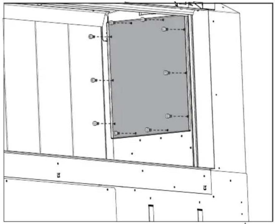
- Remove the 2 silicone tubes (making note of which tube goes on each spigot).
Disconnect the two wires from the pressure switch and remove the two screws on either side of the pressure switch to remove it from the bracket. The black hose should be connected to the low pressure port and the translucent to the high pressure port.

natural_image
Technical line drawing of a rectangular enclosure with a circular vent and mounting bracket (no text or symbols)S12 Replacing the Thermal Cut Out (TCO)
WARNING - Ensure power is turned off before removing any TCO.
There are two thermal cutouts: one in the LH room fan assembly (60°C) and the other attached to the exhaust manifold (140°C).
Exhaust TCO (140°C)
Access to this TCO by following steps 1 and 2 from section S11.
Reach into the hatch and locate the TCO (circled in the diagram below). The TCO has two wires connected to the main body; remove these. Unscrew the TCO by hand and remove from the firebox.

natural_image
Technical line drawing of a mechanical assembly with no visible text or symbolsFan TCO (60°C)
Access to this TCO by following S9 and removing the left hand fan (not exhaust side). Once the fan is removed you will see the TCO (circled in the diagram below). To remove this, unscrew the two visible screws and, once free, remove the two wires connected to the TCO. Remove the TCO from the chassis.

natural_image
Technical line drawing of a mechanical assembly with no visible text or symbolsS13 Servicing the Horizontal/Universal Vertical Powerflue
Ensure the power to the powerflue is off by disconnecting the power to the appliance inside. If the appliance has been running, allow the powerflue to cool before attempting to service it.
Servicing a Horizontal Powerflue:
If the powerflue needs servicing, the fan can be accessed from the outside of the installation for horizontal termination and accessed from within the roof space for vertical termination.
Undo the screws on the outside of the powerflue box and separate the two parts, giving you access to the fan inside.
Removing this plate gives complete access to the fan for servicing or replacement. Check that all the seals are still intact. Check that the fan electrical terminals, motor, and impeller are not corroded. Ensure there are no signs of leakage in or around the terminal.

natural_image
Simple line drawing of a cylindrical object with a flat top and circular opening, placed on a flat base (no text or symbols)When reassembling the powerflue, line up the round silicon grommets with the outlet tube of the fan and push the cowl back into place. Ensure all seals are still in place and replace all of the screws to hold the cowl in the correct position.
Servicing a Universal Vertical Powerflue:
If the UVP is internally installed remove the unit (2 in the right hand image) and replace the complete fan unit.
If the UVP is externally installed the cowl/fan unit pictured below is to be completely replaced by removing it from the liner or flashing.


flowchart
graph TD
    A["Main Circuit"] --> B["Main Cable"]
    B --> C["Network Cable"]
    C --> D["Remote Wall Terminal"]
    D --> E["Flue Fan"]
    E --> F[""Close to Wake" (N/O) Green"]
    E --> G["Purpose"]
    E --> H["Aux On/Off"]
    H --> I["AUX"]
    I --> J["AUX ON/OFF"]
    J --> K["AUX"]
    K --> L["AUX"]
    L --> M["AUX"]
    M --> N["AUX"]
    N --> O["AUX"]
    O --> P["AUX"]
    P --> Q["AUX"]
    Q --> R["AUX"]
    R --> S["AUX"]
    S --> T["AUX"]
    T --> U["AUX"]
    U --> V["AUX"]
    V --> W["AUX"]
    W --> X["AUX"]
    X --> Y["AUX"]
    Y --> Z["AUX"]
    Z --> AA["AUX"]
    AA --> AB["AUX"]
    AB --> AC["AUX"]
    AC --> AD["AUX"]
    AD --> AE["AUX"]
    AE --> AF["AUX"]
    AF --> AG["AUX"]
    AG --> AH["AUX"]
    AH --> AI["AUX"]
    AI --> AJ["AUX"]
    AJ --> AK["AUX"]
    AK --> AL["AUX"]
    AL --> AM["AUX"]
    AM --> AN["AUX"]
    AN --> AO["AUX"]
    AO --> AP["AUX"]
    AP --> AQ["AUX"]
    AQ --> AR["AUX"]
    AR --> AS["AUX"]
    AS --> AT["AUX"]
    AT --> AU["AUX"]
    AU --> AV["AUX"]
    AV --> AW["AUX"]
    AW --> AX["AUX"]
    AX --> AY["AUX"]
    AY --> AZ["AUX"]
    AZ --> BA["AUX"]
    BA --> BB["AUX"]
    BB --> BC["AUX"]
    BC --> BD["AUX"]
    BD --> BE["AUX"]
    BE --> BF["AUX"]
    BF --> BG["AUX"]
    BG --> BH["AUX"]
    BH --> BI["AUX"]
    BI --> BJ["AUX"]
    BJ --> BK["AUX"]
    BK --> BL["AUX"]
    BL --> BM["AUX"]
    BM --> BN["AUX"]
    BN --> BO["AUX"]
    BO --> BP["AUX"]
    BP --> BQ["AUX"]
    BQ --> BR["AUX"]
    BR --> BS["AUX"]
    BS --> BT["AUX"]
    BT --> BU["AUX"]
    BU --> BV["AUX"]
    BV --> BW["AUX"]
    BW --> BX["AUX"]
    BX --> BY["AUX"]
    BY --> BZ["AUX"]
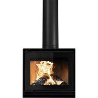
- Important:
- WARNING:
- Who can install this product:
- Warranty Repair and Annual Servicing:
- A Product Description and Installation Process 6
- B Creating the Cavity 8
- C Installing the Flue 10
- D Installing the Electricity and Gas to the Appliance 21
- E Installing the Appliance 24
- F Finishing the Installation 36
- G Installation Checklist 48
- S Service Manual 49
- A
- Product Description and Installation Process
- A1 Product Description
- A2 Recommended Install Process
- A3 Product Dimensions
- B Creating the Cavity
- B1 Cavity Shape
- B2 Designing the Cavity
- The DS1900 fire is to be installed prior to any wall lining. The wall lining is the very last task to be completed in this installation.
- Recommended Framing Dimensions
- B3 Hearth
- B4 Cavity Base
- B5 Wall Lining
- B6 Television & Mantel Clearances Television
- Mantel
- C1 Flue Configuration (If less than 8m flue length is required)
- C2 Flue Configuration (If more than 8m flue length is required)
- C3 Installing the Horizontal Powerflue Wall Terminal option
- Creating the Hole in the Outside Wall
- How to Flash the Horizontal Powerflue
- C4 Installing the Universal Vertical Powerflue (Internal Install)
- Note: The UVP-Internal and the flexi flue connections must be installed in a location accessible for service or replacement; a service hatch or removable flashing to allow access may be required.
- C5 Installing an Universal Vertical Powerflue (External Install)
- C6 Installing in Accordance with Relevant Codes
- Notes:
- C7 Running the Flue
- C8 Running the Powerflue Electrical Cable
- END OF SECTION C
- D Installing the Electricity and Gas to the Appliance
- D1 Power Supply
- D2 Network Cable
- D3 Gas Pipe Sizing
- Maximum DS1900 Gas Consumption = 49MJ/hr
- D4 Gas Pipe Position
- D5 Gas Isolating Valve
- END OF SECTION D
- E
- Installing the Appliance
- E1 Connecting the Flue
- E2 Installation
- E3 Removing (and Replacing) the Glass
- E4 Remove the Infill & Burners
- E5 Single Sided Front to Back Conversion (only for single sided fires)
- E6 Gas Type Conversion
- Step 8: Adjusting the electronic controller for gas type
- E7 Operating the Appliance
- E8 Checking the Gas Operating Pressure
- Changing the Operating Pressure from the Remote
- WAIT. Allow the appliance to fully light all burners before continuing.
- Changing from Celsius to Fahrenheit
- E9 Auxiliary On/Off button
- E10 Home Automation Setup
- Home Automation Operation
- Relay closed
- Relay open
- END OF SECTION E
- F
- Finishing the Installation
- F1 Coal or Crystalight Fuelbed Installation
- F2 Log and Woodland Log Fuelbed Retainer Setup
- Woodland Retainers
- Log Retainers
- F4 Woodland Fuelbed Installation Woodland Log Index
- F6 Wall Linings
- Frameless or Linear Trim Wall Linings
- Bevelled Lite Fascia
- F7 Fitting the Linear Trim
- F8 Fitting the Bevelled Lite Fascia
- F9 Locating Wall Mount Cradle for Wireless Control
- F10 Operating the Appliance
- F11 Normal Operating Sounds and Smells
- Sounds
- Fan:
- Gas Control Valve:
- Smells
- S1 Annual service procedure
- S2 Error Codes
- Error Code Suggested action
- S3 Cleaning the Fuel bed and Glass
- S4 Cleaning the Fascia
- For Powder Coated Fascias:
- S5 Checking Operating Pressure
- S6 Replacing a Remote Control
- S7 Replacing the Burners
- S8 Serial Number
- S9 Removing or Cleaning Fan
- S10 Removing the Control Tray
- S11 Pressure Switch Removal
- S12 Replacing the Thermal Cut Out (TCO)
- WARNING - Ensure power is turned off before removing any TCO.
- Exhaust TCO (140°C)
- Fan TCO (60°C)
- S13 Servicing the Horizontal/Universal Vertical Powerflue
- Servicing a Horizontal Powerflue:
- Servicing a Universal Vertical Powerflue:
Brand : Escea
Model : DS1900
Category : Heating