
CA280 - Water filter ASTRALPOOL - Free user manual and instructions
Find the device manual for free CA280 ASTRALPOOL in PDF.


| Brand | AstralPool |
| Model | CA280 |
| Product Type | Media Filter (Sand Filter) |
| Tank Diameter | 665 mm |
| Filter Area | 0.30 m² |
| Port Size | 40 mm |
| 6-Hour Turnover | 100,800 liters |
| 8-Hour Turnover | 134,400 liters |
| Sand Required (Standard) | 120 kg |
| Dimensions (with Valve Installed) | 106 cm (H) x 66.5 cm (W) |
| Shipping Weight | 20 kg |
| Maximum Operating Pressure | 250 kPa |
| Valve Positions | 6 (Filter, Backwash, Rinse, Waste, Closed, Recirculate) |
| Pressure Gauge | Liquid-filled glycerin, 0-250 kPa |
| Installation Base | Concrete slab or solid base recommended |
| Ventilation Requirement | Adequate ventilation for pump |
| Backwash Trigger | When pressure increases 30-40 kPa from starting pressure |
| Backwash Duration | 3-5 minutes or until sight glass runs clean |
| Rinse Duration After Backwash | 1 minute |
| Recommended Media | Quartz silica sand, glass, or zeolite |
| Warranty Registration | Register at www.astralpool.com.au/warranty |
Frequently Asked Questions - CA280 ASTRALPOOL
User questions about CA280 ASTRALPOOL
0 question about this device. Answer the ones you know or ask your own.
Ask a new question about this device
Download the instructions for your Water filter in PDF format for free! Find your manual CA280 - ASTRALPOOL and take your electronic device back in hand. On this page are published all the documents necessary for the use of your device. CA280 by ASTRALPOOL.
USER MANUAL CA280 ASTRALPOOL
CA, ECA, Series MEDIA Filters
INSTALLATION AND
OPERATING INSTRUCTIONS
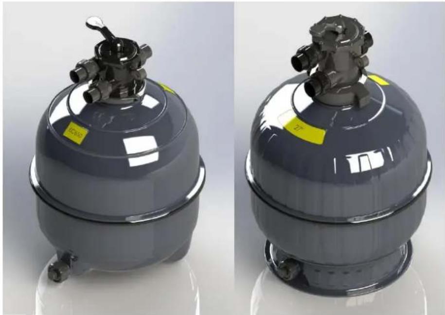
ECA SERIES FILTER CA SERIES FILTER
natural_image
Two identical industrial equipment cases with metallic components, one labeled 'ICAM' and the other 'ZT', shown side by side (no text or symbols on the devices themselves)| Model No. | Tank Diameter | Filter Area | Port Size | 6 Hr. Turnover | 8 Hr. Turnover | Sand Req'd. | VIRON ACTIVE COURSE | VIRON ACTIVE FINE |
| CA280 | 665 mm | 0.30 Sq M | 40 mm | 100,800 ltrs | 134,400 ltrs | 120 kg | 45 kg | 75kg |
| CA300 | 665 mm | 0.30 Sq M | 50 mm | 108,000 lts | 144,000 lts | 120 kg | 45 kg | 75 kg |
| CA340 | 742 mm | 0.38 Sq M | 50 mm | 115,200 ltrs | 153,600 trs | 150 kg | 60 kg | 90kg |
| CA400 | 816 mm | 0.46 sq M | 50 mm | 144,000 ltrs | 192,000 ltrs | 200 kg | 75 kg | 125kg |
| Dimensions With Valve Installed | |||
| Model | Height | Width | Shipping Weight |
| CA280 | 106 cm | 66.5cm | 20 kg |
| CA300 | 107.6 cm | 66.5cm | 21 kg |
| CA 340 | 107.6 cm | 74.2 cm | 22 kg |
| CA400 | 123.3cm | 81.6 cm | 28 kg |
ECA SERIES MEDIA FILTERS
| Dimensions With Valve Installed | |||||||||
| Model | Height | Width | Shipping Weight | ||||||
| ECA 550ECA 650 | 98 cm105 cm | 58.6 cm66.5cm | 13 kg17 kg | ||||||
| ModelNo. | TankDiameter | Filter Area | PortSize | 6 Hr.Turnover | 8 Hr.Turnover | VIRONACTIVECOURSE | VIRONACTIVEFINE | Sand Req'd | |
| ECA550ECA650 | 586 mm665 mm | 0.23 Sq M0.30 Sq M | 40 mm40 mm | 65,000 ltrs92,000 ltrs | 85,000 ltrs120,000 ltrs | 30 kg45kg | 50kg75kg | 80 kg120 kg | |
INFORMATION AND SPECIFICATIONS SUBJECT TO CHANGE WITHOUT NOTICE.
GENERAL NOTES
- When unpacking the filter, be sure the unit is complete and no visible shipping damage has occurred.
- Allow sufficient clearance around filter system for access and maintenance.
- Provide adequate ventilation for pumping equipment, installed in conjunction with filter.
- Provide solid mounting for filter and pump. If installed outdoors, install the system on a slab or solid concrete base to avoid risk of settlement. Filter systems once located with sand and water can exceed a weight of 250 kg. If installed indoors, ensure doorway allows sufficient clearance should filter tank require replacing.
- Installation of filters and pumps should be located as close to the pool as possible to avoid excessive piping friction loss.
- If system is installed below pool level it is important to install isolating valves to prevent risk of flooding from back up water, from the pool or spa.
- The proper sand selection is critical to good filter performance. Ensure that the media is an approved form of Quartz Silica sand, glass or Zeolite.
- The installation of filters requires no special tools.
- Confirm that plumbing lines from pool are correctly identified. This will ensure proper connection to markings on filter valve (i.e. "Pump", "Waste", and "Return").
Once the filter system has been positioned, the installation of filter sand may be undertaken as follows:
- Check filter size in order to determine necessary amount of sand required.
- Double check that the internal system consisting of a lateral hub and stand pipe are intact inside the tank.
- Fill tank half full with water.
- Place the disposable loading disc into the upper tank opening and the plastic cover over stand pipe to stabilise the filter and stand pipe. It is important that the stand pipe remains centered through the sand loading procedure to ensure alignment with valve assembly opening.
- Proceed to load correct volume of dry sand slowly (if sand is saturated loading can be difficult).
- Once sand is loaded discard loading disc and check to determine if stand pipe is properly centered in tank opening.
- Fill with sand, glass or other approved sand to the shoulder level of the filter.
INSTALLATION OF SELECTOR VALVE
- Following the sand loading, clean any sand particles or debris from upper surface of tank opening.
- Install six (6) position selector valve after placing O-Ring in cavity on tank body. Place valve into tank opening while ensuring that the O-Ring has remained in position.
- Install selector valve into top tank opening and rotate valve to best suit plumbing lines.
a. CA Series: once valve positioned, tighten the lock ring firmly by hand.
b. ECA Series: once valve positioned, fit clamp band assembly around neck of filter and valve and tighten sufficiently for good engagement.
c. Note: It is not necessary to over tighten.
-
Double check that incoming pool lines are connected to appropriate valve openings as marked on valve port (i.e. pump, return (pool) and waste).
-
The threaded openings on valve are 40mm or 50mm thread which all accommodate Astral Pool barrel unions supplied with the filter. O-rings are supplied to fit between the multiport valve and barrel union. It is only necessary to tighten by hand. THE USE OF TEFLON TAPE IS NOT REQUIRED.
-
Remove plug from side wall of valve and install threaded pressure gauge (if not already fitted) using Teflon tape wrap. Do not over tighten. Minimal hand tightening is adequate to provide a good seal.
NOTE:
How to correct a liquid filled gauge that has moved off of "0 psi" during shipping?
Why it happens
Liquid filled pressure and vacuum gauges are tested for accuracy at the factory. However, during transport, changes in temperature and altitude may cause a shift in the gauge's internal pressure. That, in turn, causes the gauge's resting point to change. There are no long term side effects from these changes if the gauge is vented to equalize that pressure.
If the gauge is placed in a location where big temperature changes are common, you may want to vent it when major changes occur. When installing new gauges, it is a good practice to mount them with the stopper up so that they can be vented easily
How to fix it
On top of the gauge is a rubber stopper which secures the liquid filling. To calibrate a gauge that is not returning to zero, just lift one edge of the stopper to equalize the pressure inside. Try to position the gauge so that the stopper opening is pointed upward and any air bubble inside the pressure gauge is at the near it. After venting the gauge, you should see the pointer move back to 0 psi, remember to keep the gauge vertical (stopper on top), so that the oil doesn't leak out.
If a little of the liquid escapes, just wipe it away. Astralpool uses non-toxic food grade glycerin to fill its gauges. Wiping away the excess is important however, as left over glycerin will collect dust and debris if it is not cleaned off. Replace the stopper when finished. The gauge will work without stopper replacement, but it should be put back in place to maintain a clear dial. An open top will allow dust and debris into the casing, which could cloud the readout and might damage the gauge over time.
The operation and the positions of valve settings are as follows:
| Valve Settings | Direction of flow through Valve |
| Filter (also during vacuuming) | From pump down through valve, through sand bed, up through stand pipe to valve and back through pool return. |
| Back Wash | From pump, through valve, down through stand pipe, up through sand bed, and through valve to waste. |
| Rinse | Flow from pump, through valve, down through sand bed, up through stand pipe, through valve to waste. (Position also used for initial start-up and levelling sand bed after Back-wash) |
| Waste | From pump, through valve to waste. Also position for lowering water level or assist in draining pool. |
| Closed | From pump to valve without further circulation. Prevents any flow to filter and pool. |
| Recirculate | From pump through valve to pool. This position bi-passes the filter and is used for circulation of pool water only. |
NOTE: Always "STOP" pump when changing selector valve position.
INITIAL START - UP
- Make sure the correct amount of sand is in the filter tank.
- Prime pump.
- Set valve handle in BACK WASH position.
- Start pump and operate in BACK WASH cycle for three (3) minutes. This will purge the filter of excess fines in the sand.
- Turn pump OFF and set valve handle to RINSE. Start pump and run for one (1) minute.
- Stop pump and set valve handle to FILTER. Restart pump. System is now operating on a normal FILTER cycle.
- Adjust the valves in the skimmer and main drain lines (if provided) to achieve balanced flow rates.
- When a pool is filled initially, the filter may have to be BACK WASHED once a day until the water becomes sparkling clear. From that point on, BACK WASH when pressure gauge indicates 30 to 40 kPa higher than at starting pressure.
OPERATIONAL & INSTALLATION TIPS
- Always turn pump "OFF" before changing valve positions.
- Never run pump dry as it depends on water for lubrication.
- Always maintain minimum water level to 12 way up the skimmer mouth.
- Clean pump strainer regularly.
- Maintain a proper chemical balance in the pool.
- Maximum operating pressure is 250kPa on CA Series and 200 kPa on ECA Series.
- Ensure pressure gauge on valve is positioned so that rain water cannot collect on glass face.
- Back wash filter regularly for 3-5 minutes or until sight glass runs clean each time to ensure sand is completely cleaned.
- Always rinse for 1 minute after each backwash and before returning valve position to filter.
Maintenance of your filter
Maintenance Schedule: You new product incorporates moving parts and withstands high velocity water with chemicals in it. Some of these parts will wear in the normal course of use and require regular checks and maintenance. Performing these checks and maintenance will identify parts that have worn and require repair/replacement before further serious damage is sustained. A small amount of regular care and attention to your pool equipment will help ensure long life and trouble free performance.
| Timing | Maintenance Check | Service action (if required) |
| Fortnightly | Check pressure gauge. If pressure increase is greater than 20kPa cleaning may be required | Perform backwash according to instructions |
| Three Monthly | Check inlet/outlet o’rings for leaks | Isolate Pump, turn power off, clean and grease O rings or replace if necessary |
| Annually | Compare operating pressure of backwashed filter to initial pressure (when new)If using Zeolite or M3, regenerate filter sand.This is important in commercial applications as it aids in the removal of ammonias. | If pressure is more than 30 – 40 kPa different from new filter, a sand change may be requiredAdd salt to filter sand per supplier. Allow to sit for 24 hours then backwash, rinse and return to filter. |
Important note: Regular maintenance is important to ensure long life and trouble free performance of your pool equipment. If unable to perform the maintenance yourself, contact your local AstralPool office who will arrange a trained service technician to perform the maintenance for you.
Record your Equipment details here for quick reference:
Model No.: ____
Serial No.: ____
Initial Pressure (kPa): ____
AstralPool Australia Pty Ltd (ABN 97 007 284 504) ("AstralPool") provides the following warranty in relation to its CA, ECA Series Sand Filters. ("Product").

For full warranty terms and conditions and to register your warranty, simply visit www.astralpool.com.au/warranty and complete your details. Or scan the QR code and be taken directly to the registration page.
Record your equipment details here for quick reference:
Model No.: ____
Serial No.:

INST368

sales@astralpool.com.au
www.astralpool.com.au
Brand : ASTRALPOOL
Model : CA280
Category : Water filter