
RRD6 - Range hood HONEYWELL - Free user manual and instructions
Find the device manual for free RRD6 HONEYWELL in PDF.


| Product Type | Range Hood |
| Brand | Honeywell |
| Model | RRD6 |
| Installation Type | Built-in / Under Cabinet |
| Width | 60 cm (23.6 inches) |
| Depth | 50 cm (19.7 inches) |
| Height | 15 cm (5.9 inches) |
| Weight | Approximately 12 kg (26.5 lbs) |
| Power Supply | 220-240 V, 50/60 Hz |
| Motor Power | 180 W |
| Max Airflow | 600 m³/h |
| Noise Level | 55 dB (average speed) |
| Number of Speeds | 3 |
| Lighting | 2 x LED bulbs, 3 W each |
| Filter Type | Aluminum grease filter (dishwasher safe) |
| Control Type | Sliding switch |
| Venting Type | Ducted (recirculation optional with charcoal filter) |
| Duct Diameter | 150 mm (6 inches) |
| Exhaust Location | Top or rear |
| Energy Class | B (on scale A+++ to D) |
| Maintenance | Clean grease filter monthly; replace charcoal filter every 3-6 months |
| Safety Features | Thermal overload protection |
| Spare Parts Availability | Grease filters, charcoal filters, LED bulbs available online |
| Warranty | 2 years (depending on region) |
Frequently Asked Questions - RRD6 HONEYWELL
User questions about RRD6 HONEYWELL
0 question about this device. Answer the ones you know or ask your own.
Ask a new question about this device
Download the instructions for your Range hood in PDF format for free! Find your manual RRD6 - HONEYWELL and take your electronic device back in hand. On this page are published all the documents necessary for the use of your device. RRD6 by HONEYWELL.
USER MANUAL RRD6 HONEYWELL
Retrofit Round Damper (RRD)
PRODUCT DATA
APPLICATION
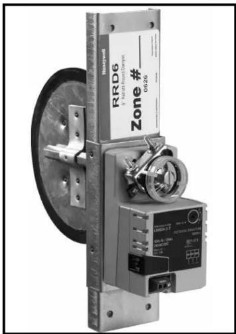
The RRD is a round damper that is easily inserted into rigid round ducts for retrofit zoning in forced air heating and cooling systems. It is available in four sizes for use in 5", 6", 7", and 8" ducts.
The damper is used with Honeywell TrueZONE®, EnviraZONE™ and similar zone control systems. The power open, power closed actuator draws 2 VA allowing multiple dampers per zone, but delivers high torque for reliable operation.
FEATURES
- Easy slide-in installation
• 2 VA allows for many dampers on one zone
• Available in 4 sizes to fit most rigid round branch ducts - Quiet, long life motor automatically shuts itself off in full open and closed positions.
• Gaskets around blade and under motor housing for low internal leakage and very low external leakage - Range stops with easy adjustment from top of motor
- Easy to see and reliable mechanical blade position indicator
- Easy to hook up with conventional thermostat wire
- Simple manual blade positioning with push button gear release
SPECIFICATIONS
IMPORTANT
The specifications given in this manual do not include normal manufacturing tolerances. Therefore, this unit may not exactly match the listed specifications. In addition, this product is tested and calibrated under closely controlled conditions, and some minor differences in performance can be expected if those conditions are changed.
Contents
| Application | 1 |
| Features | 1 |
| Specifications | 1 |
| Ordering Information | 2 |
| Installation | 3 |
| Wiring | 3 |
| Adjustments | 4 |
| Checkout | 4 |
| Troubleshooting | 4 |
Construction
Frame: 18 gauge G-60 or G-90 galvanized steel C channel with gasket, 20 gauge actuator mounting bracket.
Blade: 20 gauge G-60 or G-90 galvanized steel surrounded by a black EPDM rubber gasket.
Shaft: 1/2" hex damper blade shaft of cold rolled zinc electroplated steel. The shaft runs through a white nylon bushing.
Sizes: 5.125", 6.125", 7.125", 8.125" diameters
Electrical Rating: 24 VAC, 50 or 60 Hz
Power Consumption: 1.5 watts running. Transformer sizing VA: 2.
Wiring Terminals: Screw terminals for 14 to 26 gauge wire labeled: M1 (Common), M4 (counter-clockwise, open), M6 (clockwise, closed)
Nominal Angular Rotation: 90°
Torque: 45 in. lb, (5 Nm)
Nominal Timing: 90 seconds independent of load
Ambient Ratings: -40° F (-40° C) to 122° F (50° C), 5-95% RH non-condensing
Mounting: Direct couple to 1/2" shaft
Agency Listings: NEMA 1, UL listed, class two
Dimensions: See Fig. 1–2
Weight:
RRD5: 3.6 lb
RRD6: 3.8 lb
RRD7: 4.1 lb
RRD8: 4.3 lb
Leakage (Closed): 3.4% at .5" WC
Pressure Drop (Open): <.05" WC
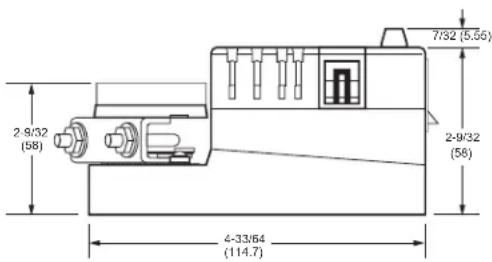
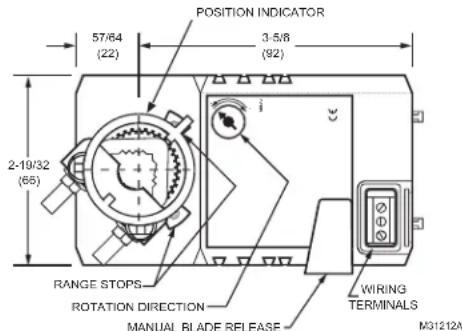
Fig. 1. Motor dimensions in in. (mm).
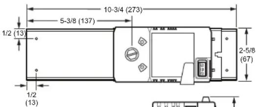
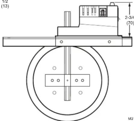
Fig. 2. RRD damper.
ORDERING INFORMATION
When purchasing replacement and modernization products from your TRADELINE® wholesaler or distributor, refer to the TRADELINE® Catalog or price sheets for complete ordering number.
If you have additional questions, need further information, or would like to comment on our products or services, please write or phone:
-
Your local Honeywell Automation and Control Products Sales Office (check white pages of your phone directory).
-
Honeywell Customer Care
1885 Douglas Drive North
Minneapolis, Minnesota 55422-4386
In Canada—Honeywell Limited/Honeywell Limitée, 35 Dynamic Drive, Toronto, Ontario M1V 4Z9.
International Sales and Service Offices in all principal cities of the world. Manufacturing in Australia, Canada, Finland, France, Germany, Japan, Mexico, Netherlands, Spain, Taiwan, United Kingdom, U.S.A.
INSTALLATION
Before Installing this Product
- Read all instructions before installing this product. Failure to follow instructions can damage the product or cause a hazardous condition.
- Check the ratings given in the instructions and on the product to verify that the product is suitable for your application.
- Installer must be a trained and experienced service technician.
- Install the product in an area that is easily accessible for checkout and service.
- After completing installation, use these instructions to check out product operation.
Installing the Retrofit Round Damper
Select a location for the damper in the ductwork. It is suggested that the RRD damper be at least 6 feet from the register for quiet operation.
- Peel off the back of the cut-out template. Carefully align the template with the centerline of the duct. Apply template to the section of round ductwork where the damper is to be installed. Ensure that the template is parallel to the ductwork. It is suggested that the damper be installed with the motor under a horizontal duct to reduce twist to the duct. It may also be necessary to support the duct.
- Drill a starter hole in the cut-out area of the template.
- Cut out the area between the holes.
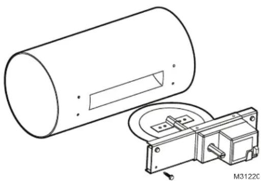
- Slide the damper into the duct and secure it with the four supplied self-drilling mounting screws. Be careful to avoid over-tightening the screws as the duct may be pulled out of round. See Fig. 3.
natural_image
Technical line drawing of a cylindrical mechanical component with a separate inset showing a bracket and mounting base (no text or symbols)Fig. 3. Inserting RRD damper into duct.
WIRING
Wiring the Motor Actuator
Connect the motor to the zone control panel 18 or 20 gauge wire. The motor terminals are labeled M1 for common, M4 for open, and M6 for closed. Connect the motor terminals to corresponding terminals on zone control panel for each zone. See Fig. 4–6 for hookups.
Multiple RRD dampers can be wired to one zone when wired in parallel. See Fig. 5 for wiring multiple dampers together in a daisy chain manner or Fig. 6 using wire nuts. See Table 1 for
the maximum number of dampers that can be connected to each zone control panel. Note that this is the total number of dampers connected to all the zones of a zone control panel; the maximum dampers per zone is 14. If more than 14 dampers are on one zone, a Slave Damper Control Relay (SDCR) must be used.
When more than the maximum number of dampers allowed per panel are necessary, a SDCR must be used. The SDCR is an isolation relay that is powered by a separate transformer so that it relieves the panel of this additional load. When a SDCR is used, the dampers of that zone may either be all connected to the SDCR, or some dampers may be wired to the SDCR and the remainder to that zone's damper terminals.
Maximum number of dampers per zone.
| One 40 VA Transformer | Two 40 VA Transformers (or One 75 VA) | |
| TrueZONE® Panels* | 13 27 | |
| W8835* 12 26 | ||
| SDCR 15 28 |
*Maximum of 14 dampers per zone
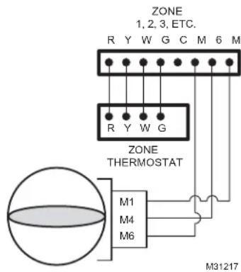
Fig. 4. RRD wired to zone control panel.
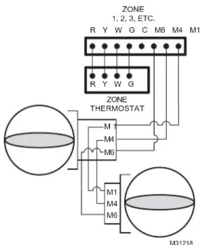
Fig. 5. Wiring multiple RRD dampers in daisy chain fashion.
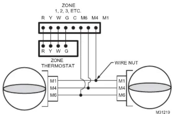
Fig. 6. Wiring multiple RRD dampers using wire nuts.
ADJUSTMENTS
Manual Blade Adjustment
To verify correct range of motion, depress the manual blade adjustment button. While this is pressed, the gears are disengaged, allowing the blade to be manually opened or closed by turning the damper blade shaft. See Fig. 1.
Position Indicator
The position indicator (shown in Figure 1) points toward the position of the damper blade to identify if the blade is open, closed, or at an intermediate position. A slot at the end of the damper blade shaft also indicates blade position.
Range stops
The RRD damper motor can be adjusted to prevent complete closure of the blade. This is useful in zone systems where it is not possible to install a bypass damper.
To set the range stop to prevent complete closure:
- Locate the range stop adjustment screw on the top of the motor to the right blade shaft. This is at the extreme counter-clockwise end of travel.
- Using a small Phillips head screwdriver, loosen the set screw.
- Move the end-stop block to the new position
- Secure the set screw.
- Verify the new range of motion while depressing the manual blade release button.
TROUBLESHOOTING
| Damper operates backwards | Verify correct damper wiring as shown in Fig. 4–6. Also verify that the Rotation Direction screw is in the "0" position as shown in Figure 1. |
| Damper does not operate | 1. Verify damper wiring using checkout methods listed in this document.2. Verify that the duct is round and not making the blade stick. Depress the manual blade release button and manually turn the blade shaft to verify smooth opening and closing operation. |
Automation and Control Solutions
Honeywell International Inc.
1985 Douglas Drive North
Golden Valley, MN 55422
Toronto, Ontario M1V 4Z9
customer.honeywell.com
® U.S. Registered Trademark
© 2010 Honeywell International Inc.
69-1960ES—01 E.K. Rev. 02-10
Printed in U.S.A.
Honeywell
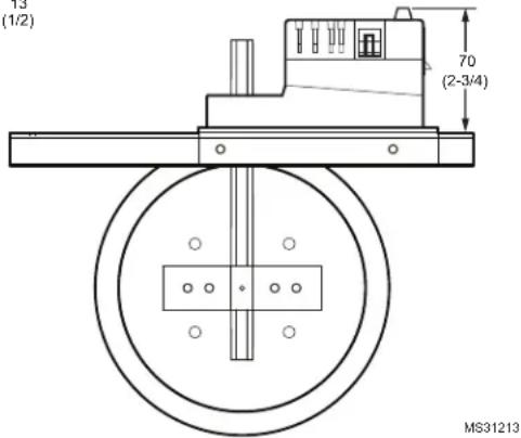
Fig. 2. regulador RRD.
1885 Douglas Drive North
Golden Valley, MN 55422-4386
natural_image
Technical line drawing of a cylindrical mechanical component and its internal assembly (no text or symbols)Honeywell International Inc.
1985 Douglas Drive North
Golden Valley, MN 55422
Toronto, Ontario M1V 4Z9
customer.honeywell.com
- Retrofit Round Damper (RRD)
- APPLICATION
- FEATURES
- SPECIFICATIONS
- IMPORTANT
- Construction
- Weight:
- ORDERING INFORMATION
- INSTALLATION
- Before Installing this Product
- Installing the Retrofit Round Damper
- WIRING
- Wiring the Motor Actuator
- ADJUSTMENTS
- Manual Blade Adjustment
- Position Indicator
- Range stops
- Automation and Control Solutions
Brand : HONEYWELL
Model : RRD6
Category : Range hood