
VC-4-CORE - Software Crestron - Free user manual and instructions
Find the device manual for free VC-4-CORE Crestron in PDF.


| Product Type | Virtual Control System Core |
| Brand | Crestron |
| Model | VC-4-CORE |
| Dimensions (W x D x H) | 17.0 x 12.0 x 1.7 inches (1U rackmount) |
| Weight | 5.5 lbs (2.5 kg) |
| Power Supply | 100-240V AC, 50/60 Hz, 50W max |
| Processor | Quad-core ARM Cortex-A72 |
| Memory | 4 GB DDR4 |
| Storage | 32 GB eMMC |
| Ethernet | 2x Gigabit Ethernet |
| USB Ports | 2x USB 3.0, 2x USB 2.0 |
| HDMI Output | 1x HDMI 2.0 (4K60) |
| Serial Ports | 2x RS-232, 1x RS-485 |
| IR Ports | 4x IR output, 1x IR input |
| Relays | 2x relay outputs |
| Operating System | Crestron VC-4 |
| Key Functions | Virtual control system, AV switching, room control, scheduling, integration |
| Cooling | Fanless, passive cooling |
| Mounting | 1U rackmount, included rack ears |
| Safety Certifications | UL 62368-1, CE, FCC Part 15 |
| Operating Temperature | 0°C to 40°C (32°F to 104°F) |
| Humidity | 10% to 90% non-condensing |
| Maintenance | Clean with dry cloth; no internal user-serviceable parts |
| Spare Parts | Contact Crestron service for replacement parts |
Frequently Asked Questions - VC-4-CORE Crestron
User questions about VC-4-CORE Crestron
0 question about this device. Answer the ones you know or ask your own.
Ask a new question about this device
Download the instructions for your Software in PDF format for free! Find your manual VC-4-CORE - Crestron and take your electronic device back in hand. On this page are published all the documents necessary for the use of your device. VC-4-CORE by Crestron.
USER MANUAL VC-4-CORE Crestron
.AV Framework™ Software for
Crestron Virtual Control
Software
Operations Guide
Crestron Electronics, Inc.
Original Instructions
The U.S. English version of this document is the original instructions.
All other languages are a translation of the original instructions.
Crestron product development software is licensed to Crestron dealers and Crestron Service Providers (CSPs) under a limited non-exclusive, non-transferable Software Development Tools License Agreement. Crestron product operating system software is licensed to Crestron dealers, CSPs, and end-users under a separate End-User License Agreement. Both of these Agreements can be found on the Crestron website at www.crestron.com/legal/software-license_agreement.
The product warranty may be found at www.crestron.com/legal/sales-terms-conditions-warranties.
The specific patents that cover Crestron products are listed at www.crestron.com/legal/patents.
Contents
Introduction....1
Product Features....2
Setup....4
Load the Program Files 4
Add .AV Framework Rooms....7
Generate an Authentication Token....9
Access the Configuration Utility....11
Add an A/V Switcher 14
Add New Devices....18
Configuration....20
Navigate the Configuration Utility....20
Status Menu....20
AV Framework Dashboard.... 21
AVF Log 24
Configure Menu 25
System Setup....26
Device Management....38
Inputs/Outputs....43
Manage Configuration....44
Users Menu 47
Operation....49
Display Overview....49
Home Screen Overview....50
No Scheduling Calendar Connected 50
Crestron Fusion....71
Connect to Crestron Fusion....71
Room Control and Monitoring....75
Appendix B: Device Configuration 78
AirMedia....78
Blu-ray™ Player....78
Button Panel 79
Cable TV....79
Cresnet Gateway....79
Crestron IO 80
DigitalMedia Transmitter....80
Flat Panel Display 81
Occupancy Sensor 82
Projector 83
Room Availability Hallway Sign....83
Touch Screen 84
Video Server 84
.AV Framework™ Software for Crestron Virtual Control Software
Introduction
Crestron® .AV Framework™ software is a web-based management solution that is used to deploy scalable Crestron enterprise room solutions without requiring any programming. The .AV Framework configuration utility is accessible from most web browsers and provides the following functions:
- Select sources and displays.
- Configure device control for Blu-ray Disc® players, cable TV boxes, and video servers.
- Add a compatible touch screen to generate the GUI for a single or multiple display systems.
- Add a compatible button panel to control single display systems.
- Connect to Crestron Fusion® software to monitor and control basic room data, system power, source selection, and room scheduling.
- Customize the .AV Framework user experience with additional components, custom functionality, and corporate logos.
.AV Framework is compatible with the Crestron Virtual Control series of server-based control systems. Add the .AV Framework program to a room on the Crestron Virtual Control server, and then add a supported Crestron A/V auto-switcher device or a virtual
Product Features
Refer to the following chart to determine the devices and product features that are compatible with .AV Framework for Crestron Virtual Control (VC-4).
.AV Framework Product Feature Chart
| FEATURE CLASS FEATURE VC-4 | ||
| AirMedia® Presentation Gateway | AM-100 | Yes |
| AM-101 | Yes | |
| AM-200 | Yes | |
| AM-300 | Yes | |
| Button Panel | MP-B10 (Ethernet) | Yes |
| MP-B10 (Cresnet) | Yes ^1 | |
| MP-B20 (Ethernet) | Yes | |
| MP-B20 (Cresnet) | Yes ^1 | |
| Cable Caddy | TT-100 (Cresnet) | Yes ^1 |
| TT-100 (USB) No | ||
| TT2-100 (Cresnet) | Yes ^1 | |
| TT2-100 (USB) No | ||
| Switcher | HD-MD-510-4K-C-E | Future release |
| HD-MD-200-C-E | Yes | |
| HD-MD-200-C-1G-E | Yes | |
| HD-MD-300-C-E | Yes | |
| HD-MD-400-C-E | Yes | |
| HDI-MD-400-C-2G-E | Yes | |
| AM-200 | Yes | |
| AM-300 | Yes | |
| Virtual Switcher | Yes | |
| Endpoint (continued) | DM-RMC-4KZ-100-C | No |
| DM-RMC-4KZ-SCALER-C | No | |
| DM-TX-4KZ-202-C | No | |
| DM-TX-4KZ-302-C | No | |
| Room Sign | SSW/SSC-PCB | Yes ^1 |
| Touch Screen | TSW-752 | Yes |
| TSW-1052 | Yes | |
| TSW-760 | Yes | |
| TSW-1060 | Yes | |
| Web XPanel | Yes | |
| Control Modules | DIN-CEN-CN-2 | Yes |
| C2N-IO | Yes ^1 | |
| CEN-IO-COM-102 | Yes | |
| CEN-IO-IR-104 | Yes | |
| CEN-IO-RY-104 | Yes | |
| Drivers | Display/Projector | Yes ^1 |
| Cable Box | Yes ^1 | |
| Blu-ray Disc Player | Yes ^1 | |
| Video Server | Yes ^1 | |
| Driver Portal Search | Yes | |
| Driver Portal Import | Yes | |
| Projector Screen | Relay Control | Yes with CEN-IO-RY-104 |
| Volume Control | DSP No | |
| Display/Projector | Yes | |
| Displays | Number of Displays 1 | |
| External Amplifier Support | Yes | |
(10) MPJ
Setup
.AV Framework for Crestron Virtual Control can be installed and configured using the Firefox ^® , Internet Explorer ^® , Microsoft Edge ^® , Safari ^® browser, or Chrome ^® web browsers.
Load the Program Files
Download the .AV Framework program for Crestron Virtual Control from the Crestron Virtual Control product pages or from the Software & Firmware section at https://www.crestron.com/Support.
The zipped package file includes the following components:
NOTE: The program and project files must be used as a version-matched pair and cannot be edited or customized.
• The .AV Framework program file (AVFPlugin[Version#].cpz)
• The touch screen project file (AVF_UI_1050_[Version#].vtz)
• Web XPanel interface files (AVFWebX.zip)
- Configuration page files (index.zip)
To upload the .AV Framework program to the Crestron Virtual Control server:
NOTE: The Crestron Virtual Control server must be installed and configured completely prior to loading the .AV Framework program. For more information, refer to the Crestron Virtual Control Installation Guide (Doc. 8274) and the Crestron Virtual Control Deployment Guide (Doc. 8272).
- Download and extract the contents of the .AV Framework for Crestron Virtual Control zipped package file to a location on the network that can be accessed by the Crestron Virtual Control web user interface.
2 Enter "http://ServerIRPI1/VirtualControl/config/settings/" into a supported
Crestron Virtual Control Web User Interface

- Select Add Program from the Actions drop-down menu on the top-right of the configuration utility.
Actions Menu

Add Program Dialog Box - Enter Details

- Enter a user-defined name for the program and a description (optional) in the appropriate text fields.
- Click Choose, navigate to the extracted package file contents on the network, and select the AVFPlugin[Version#].cpz program file.
- Click Next.
- Click Choose next to a file type to select the necessary .AV Framework program file, and the click Upload to upload the file to the program. The following files must be uploaded:
a. For XPanel (Web), select and upload the AVFWebX.zip file.
b. For Configuration Pages, select and upload the index.zip file.
c. For TSW Project, select and upload the AVF_UI_1052_[Version#].vtz file.
Add Program Dialog Box - Choose Files

- Click Add. The program files are added to the server.
The touch screen project .vtz file can be loaded to a supported touch screen or to XPanel as a custom project. The touch screen project provides a user interface for controlling the .AV Framework room.
- For more information on loading the .vtz file to a supported touch screen, refer to the touch screen documentation at www.crestron.com/manuals.
- For more information on loading the .vtz file to XPanel, refer to "XPanel" on page 65.
Add .AV Framework Rooms
Once the .AV Framework program is uploaded to the Crestron Virtual Control server, it can be used to add one or more rooms to the server.
For more information on adding and using rooms with Crestron Virtual Control, refer to the embedded help file by clicking the help button ? on the top right of the configuration utility.
To add the .AV Framework program to a room:
- Click the Status tab.
- Click Rooms to open the Rooms section (if it is not open already).
Status Tab - Rooms

Add Room Dialog Box
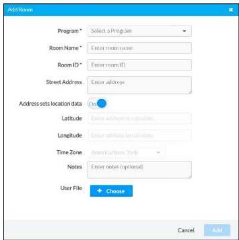
- Use the Program drop-down menu to select the .AV Framework program.
- Enter a room name, room ID, location information (optional), and notes (optional) using the appropriate text fields and drop-down menus.
NOTES:
- Multiple rooms can run the same .AV Framework program. However, each room must have a unique room name and room ID to differentiate
Status Tab - Rooms (Room Added)

- Repeat steps 3–6 for any other rooms that will be added using the .AV Framework program.
Generate an Authentication Token
A token generated by the Crestron Virtual Control server is required to access the .AV Framework configuration utility prior to initial login. The Crestron Virtual Control server authenticates this token when the login request is sent.
Settings Page - Tokens

- Click + Add Token. The Add Token dialog box displays.
Add Token Dialog Box

-
Enter a descriptive name for the token in the Description text field.
-
Click Add. A token is generated and added to the interface.
Tokens

Access the Configuration Utility
Configure settings for the .AV Framework room using the web-based configuration utility. The configuration utility for each .AV Framework room is accessible from the Crestron Virtual Control web interface.
To access the configuration utility for an .AV Framework room from the Crestron Virtual Control web interface:
NOTE: Prior to accessing the configuration utility, ensure that all devices in the .AV Framework room have been updated to their latest firmware versions.
- Click the Status tab.
- Click Rooms to expand the Rooms section.
Status Tab - Rooms

Status Tab - Details

- Click the link next to Configuration URL. The .AV Framework login page is displayed.
.AV Framework Login Page

7. Click Sign In.
Upon successful login, the AV Framework Dashboard page (the utility's default page) is displayed.
AV Framework Dashboard Page

Add an A/V Switcher
A compatible A/V switcher must be added to the .AV Framework room before any other devices can be added or edited. .AV Framework for Crestron Virtual Control supports two types of A/V switchers:
- Crestron auto-switcher devices (AM-200, AM-300, HD-MD-200-C-E, HD-MD-200-C-1G-E, HD-MD-300-C-E, HD-MD-400-C-E, and HDI-MD-400-C-2G-E)
• Virtual switchers (via supported Crestron Connected displays or projectors)
NOTE: Only one A/V switcher can be added per room.
To add an A/V switcher to the .AV Framework room:
- Select Device Management from the Configure drop-down menu. The Device Management page is displayed.
Device Management Page
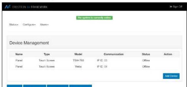
- Enter the following information for the A/V switcher:
a. Select Switcher from the Device Type drop-down menu.
b. Enter a descriptive name for the switcher in the Display Name text field.
c. Select the switcher model from the Model drop-down menu.
d. For a Crestron auto-switcher device, enter the IP address of the switcher on the network in the IP text field.
- Click Save.
The A/V switcher is added to the list of devices on the Device Management page. Other devices can now be added to the room.
Device Management Page (Switcher Added)

To add a flat panel display or projector to the room:
- Click Add Device. The Add New Device dialog box is displayed.
Add New Device Dialog Box

- Enter the following information for the flat panel display or projector:
a. Select the appropriate device type (Flat Panel Display or Projector) from the Device Type drop-down menu.
b. Enter a descriptive name for the device in the Display Name text field.
c. Select the device model from the Model drop-down menu.
d. Enter any transport control, warm up/cool down, or authentication settings required for the device. For more information, refer to "Device Management" on page 38.
- Click Next. A dialog box is displayed indicating the device driver installation status and the device connection status.
Installing Display01 Dialog Box
The flat panel display or projector is added to the list of devices on the Device Management page. Other devices can now be added to the room.
Device Management Page (Virtual Switcher Added)

NOTE: Drivers for flat panel displays and projectors are generic, and the device inputs provided in .AV Framework may not match the physical inputs on the device. If an unsupported input is selected in the touch screen user interface, the route may not be completed. Therefore, all unsupported inputs should be disabled on the Inputs/Outputs page. For more information, refer to "Inputs/Outputs" on page43.
Add New Devices
After adding an A/V switcher to the .AV Framework room, additional devices can be added to the room via wired and wireless connections to the A/V switcher and to the server. For more information, refer to "Appendix A: Interface Setup" on page 61.
To add devices to the .AV Framework room:
- Select Device Management from the Configure drop-down menu. The Device Management page is displayed.
Device Management Page (Switcher Added)
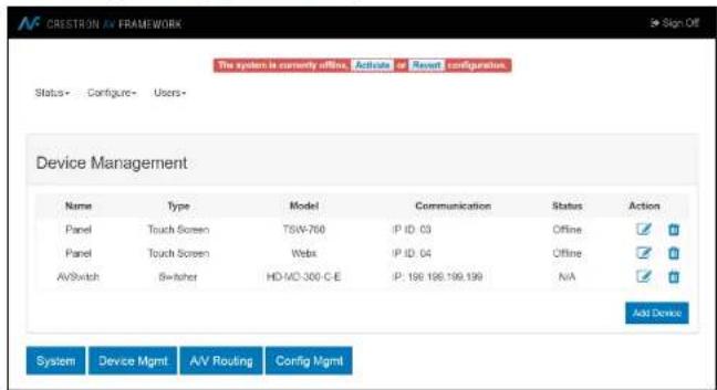
- Click Add Device. The Add New Device dialog box is displayed.
Add New Device Dialog Box
- Enter the following information for the device:
a. Select the appropriate device type from the Device Type drop-down menu.
b. Enter a descriptive name for the device in the Display Name text field.
c. Select the device model from the Model drop-down menu.
d. Enter any additional settings for the device in the appropriate fields (if required). For more information, refer to "Device Management" on page 38.
- Click Save.
The device is added to the list of devices on the Device Management page.
Device Management Page (Device Added)

Configuration
Use the configuration utility to configure system settings, to add devices and an A/V switcher to the .AV Framework room, to configure the inputs and outputs of the A/V switcher, and to manage saved configurations.
The configuration utility also provides screens that display the system status and an activity log, as well as screens for adding and managing users.
Navigate the Configuration Utility
The AV Framework Dashboard page is the default page that is displayed upon logging in, as shown in the image on the following page.
Use the drop-down menus on the top left of the screen to navigate the configuration utility. The menus are always visible on the top left of any of the configuration pages and provide the following selections.
- Status
- Dashboard
- AVF Log
- Configure
- System
- Device Management
- A/V Routing
- Configuration Management
- Users
- Manage
AV Framework Dashboard
Navigate to Status > Dashboard to display the AV Framework Dashboard page.
AVF Dashboard Page

The AV Framework Dashboard page provides the following information.
Ethernet Information
The Ethernet Information section shows the hostname, the IP address, the subnet mask address, and the default router address of the Crestron Virtual Control server.
AV Framework Dashboard - Ethernet Information
| Ethernet Information | |||
| Host Name: | ubuntu | IP Address: | 172.30.16.62 |
| Subnet Mask: | 255.255.255.0 | Default Router: | 172.30.16.1 |
Switcher Information
The Switcher Information section shows the name and model of the connected A/V switcher, as well as the channel number and icon, the channel name, the channel type, and the channel status (Online, Offline, or N/A).
NOTE: A compatible A/V switcher must be added to the .AV Framework room before any switcher information is shown. For more information on adding an A/V switcher, refer to "Add an A/V Switcher" on page 14.
AV Framework Dashboard - Switcher Information
| Switcher Information | |
| Model: | HD-MD-300-C-E |
| Input Channels | Output Channels |
The status for input and output channels indicates the following information:
- Online
- Input: The source is sending content.
- Output: The sync is receiving content.
- Offline
- Input: The source is not sending content or is not present.
- Output: The sync is not receiving content or is not present.
- N/A: The device status is not reported (shown for CEC-controlled displays, non-controlled displays, and IR-controlled devices).
Equipment
The Equipment section shows the name, model, and status (Online, Offline, or N/A) of any equipment connected to the .AV Framework room, including the A/V switcher.
AV Framework Dashboard - Equipment

For more information on connecting equipment to .AV Framework, refer to "Add New
The status for connected equipment indicates the following information:
• Online: The device is detected and is providing feedback to .AV Framework.
- Offline: The device was detected at one point, but it is no longer detected by .AV Framework.
- N/A: The device status is not reported (shown for CEC-controlled displays, non-controlled displays, and IR-controlled devices).
AVF Log
Navigate to Status > AVF Log to display the AVF Log page.
AVF Log Page
![The system is currently online. Status• Configure• Users• AVF Log 1:08:13:00:3411:Lbs09b0b17244444444444444444444444444444444444444444444444444444444444444444444444444444444444 Creator.SimpleSharp.WebScripting,HttpDomCookieCollection.Acd Recreation.SimpleSharp.WebScripting,HttpDomCookie collections [0x00073] in <30002f2d0d7a1bba2006e52b622f3e5e8 Copyright.SimpleSharp.WebScripting,HttpDomResponse,AppendCookie Recreation.SimpleSharp.WebScripting,HttpDomCookie collections [0x00079] in <30002f2d0d7a1bba2006e52b622f3e5e8 Copyright.SimpleSharpFramework.Mvc.CN03LipContext.ScodeSequence (System.Byte) name, System.String containsType, System.Object[] cookies, FV6.0Table 2[System.String,SystemsString() headersProvider] [0x00082] in <01:08:13:00:3411:Lbs09b0b1724444444444444444444 <1:08:13:00:35332 Linfo: 169 :IDM Secure store returned empty or null. Key/SBPassword <1:08:13:00:35332 Linfo: 169 :IDM Secure store returned empty or null. Key/SBPasswordid <1:08:13:00:35332 Linfo: 169 :IDM Secure store returned empty or null. Key/LdayPasswordid <1:08:13:00:35337 Linfo: 169 :IDM Secure store returned empty or null. Key/Verzny](/content/2026/05/926742/images/62b26050eb23ad4321ef9f041ca3c0e5adc7fb4939afee3863f0e47bab2f4f2a.jpg)
Configure Menu
The Configure menu provides selections for configuring system settings,
Crestron Fusion software connection settings, relay behavior settings, custom logos, and
device drivers.
The Configure menu also provides selections for adding devices to
the .AV Framework room, for configuring the input and output channels of the
connected A/V switcher, and for managing configuration settings.
Navigational controls are provided on the bottom of each configuration page:
- Select System to display the System Setup page.
- Select Device Mgmt to display the Device Management page.
- Select A/V Routing to display the Inputs/Outputs page.
- Select Config Mgmt to display the Manage Configuration page.
These menu selections are described in the sections that follow.
If any changes are made to the .AV Framework system settings from, the Configure menu, a warning message is displayed.
Warning Message
Warning
Any saved changes will place the system offline. You/User must activate
new configuration to bring the system online. Click OK to proceed.
OK Cancel
System Setup
Navigate to Configure > System to display the System Setup page.
System Setup Page

The system setup page provides tabs for configuring the .AV Framework system settings, Crestron Fusion settings, relay commands, custom graphics, and device drivers.
System
Click the System tab to display the System settings.
System Setup - System
Use the System settings to configure general settings for .AV Framework.
• Room Name: Enter a name for the room associated with the system.
- Language: Use the drop-down menu to select the language displayed by .AV Framework.
- Time Format: Use the drop-down menu to select between 12-hour and 24-hour format for displaying time.
- Date Format: Use the drop-down menu to select a format for displaying the date.
- Synchronize Room Name with VC-4: Toggle the switch to enable or disable synchronizing the .AV Framework room name with the Crestron Virtual Control room name. If enabled, the room name will update in both locations after the room is stopped and restarted in the Crestron Virtual Control web interface.
NOTE: When an existing configuration is upgraded or uploaded, room name sync is disabled by the software and must be manually enabled afterwards.
Click Save to save the current settings.
Crestron Fusion
Click the Crestron Fusion tab to display the Crestron Fusion settings.
System Setup - Crestron Fusion

- Crestron Fusion Room Name: Enter the room name in Crestron Fusion associated with the Crestron Virtual Control server.
• IPID: Enter the IP ID of the selected Crestron Fusion room. - Enable Crestron Fusion Scheduling: Use the drop-down menu to enable or disable Crestron Fusion scheduling for .AV Framework.
- Show Broadcast Message on Touch Screen: Toggle the switch on or off to enable or disable showing broadcast messages from Crestron Fusion on a connected touch screen.
- Emergency Message Timeout: Enter the time, in minutes, it takes for an emergency broadcast from the Crestron Fusion server to time out.
- Non-Emergency Message Timeout: Enter the time, in minutes, it takes for a non-emergency broadcast from the Crestron Fusion server to time out.
For more information about connecting .AV Framework to Crestron Fusion, refer to page 71.
NOTE: .AV Framework for Crestron Virtual Control supports only inbound communications for connecting to a Crestron Fusion Cloud server. Traditional (outbound) communications for connecting to an on-premises server are not supported.
Click Save to save the current settings. Click Enable to enable a connection to Crestron Fusion. Click Disable to disable the connection.
Relay
Click the Relay tab to display the Relay settings.
System Setup - Relay
System Setup
Use the Relay settings to select a relay behavior for connected video display sources, such as a projector. A relay device must be added to the system to view these settings.
• Relay Name: Enter a name for the relay.
- Relay Device & Identifier: Use the drop-down menu to select a relay pair from the available configured devices.
NOTE: A specific device relay pair can have only one saved configuration.
- Relay Behavior: Use the drop-down menu to select one of the following relay behaviors for the chosen relay pair:
- Momentary: The chosen video source is set (turned on) or reset (turned off) by a relay command and remains in the selected state for the duration specified in the Timing field.
- Latching: The chosen video source is set (turned on) or reset (turned off) by a relay command and remains in the selected state until an inverse relay command is sent.
- Disable: Relay behavior is disabled for the chosen video source.
- Timing: If Momentary is selected for Relay Behavior, enter the duration in seconds that the video source remains in a specified state following a relay command.
Click Save to save the current settings. Click Enable to enable the relay settings. Click Disable to disable the relay settings.
Touch Screen Custom Graphics
Click the Touch Screen Custom Graphics tab to display the Touch Screen Custom Graphics settings.
System Setup - Touch Screen Custom Graphics

Use the Touch Screen Custom Graphics settings to enable or disable a custom logo graphic, to enable or disable a custom touch screen screensaver, and to select custom screensaver backgrounds for a connected touch screen:
- Enable Custom Logo Graphic: Toggle the switch to enable or disable setting a custom logo graphic for the touch screen project. Custom logo graphics can be set only if .AV Framework is not connected to Crestron Fusion.
- Custom Logo Graphic URL: If Enable Custom Logo Graphic is selected, enter the URL of the desired custom logo graphic source file.
NOTES:
- .AV Framework allocates an area of 800 x 600 pixels for the custom logo graphic. Custom graphics larger than 800 x 600 pixels are not accepted and must be scaled down manually. Custom graphics smaller than 800 x 600 pixels are not scaled up, so these graphics should be resized for optimal image quality.
• Supported custom graphic file types are BMP, JPG, and PNG.
- Enable Touch Screen Screensaver: Toggle the switch to enable or disable a touch screen screensaver for the touch screen project.
- Enable Start Button: If Enable Touch Screen Screensaver is enabled and if .AV Framework is not connected to a scheduling calendar, toggle the switch to enable or disable adding a START button to the touch screen project.
NOTE: The START button is used to switch to the system's default route for systems that are not connected to a scheduling calendar. For more information, refer to "Home Screen Overview" on page 50.
- Start Button Text: If Enable Start Button is enabled, enter the text that is displayed on the Start button in the touch screen project.
- Enable Custom Screensaver Backgrounds: If Enable Touch Screen Screensaver is selected, then the switch or effect can be available as a custom background.
- Add Custom Screensaver Background URL: If Enable Custom Screensaver Backgrounds is selected, enter the URL of the desired custom background image source file.
NOTE: Observe the following points when choosing a custom background image source file:
- Up to 15 custom background URLs can be added. Select the plus (+) button next to a text field to add a new background URL once the URL has been entered. Select the minus (-) button next to an existing background URL to delete the URL. At least one background is required if Enable Custom Screensaver Backgrounds is enabled.
-
.AV Framework allocates an area of 800 x 600 pixels for the custom screensaver background graphic. Custom graphics larger than 800 x 600 pixels are not accepted and must be scaled down manually. Custom graphics smaller than 800 x 600 pixels are not scaled up, so these graphics should be resized for optimal image quality.
• Supported custom graphic file types are BMP, JPG, and PNG. -
Interval Between Backgrounds: Enter the duration in seconds that a background image is displayed on the screensaver before switching to the next image.
- Touch Screen Screensaver Sleep Time: Enter the time in seconds that the touch screen must be idle before the screensaver is activated.
- Touch Screen Screensaver Start Time: Enter the time of day in 24-hour format when the screensaver becomes active.
- Touch Screen Screensaver End Time: Enter the time of day in 24-hour format when the screensaver becomes inactive.
- Enable Touch Screen Auto Update: Toggle the switch to enable or disable automatic updates for the .AV Framework .vtz project file on a supported touch screen. Touch screen automatic updates behave as follows:
- Custom Help Page URL: If Enable Custom Help Page is selected, enter the URL of the desired custom help graphic source file.
NOTES:
- .AV Framework allocates an area of 800 x 600 pixels for the custom help file graphic. Custom graphics larger than 800 x 600 pixels are not accepted and must be scaled down manually. Custom graphics smaller than 800 x 600 pixels are not scaled up, so these graphics should be resized for optimal image quality.
• Supported custom graphic file types are BMP, JPG, and PNG.
Click Save to save the current settings.
Drivers
Click the Drivers tab to display the Drivers settings
System Setup - Drivers
| Manufacturer : | Supported Series : | Device Type : | Communication : | Driver Version : | Enable Driver |
| NEC | NEC MultiSync P NEC MultiSync V NEC MultiSync X | Flat Panel Display | IP | 2.01.003.0213 | |
| NEC | NEC MultiSync P NEC MultiSync V NEC MultiSync X | Flat Panel Display | Serial | 2.01.003.0213 | |
| NEC | Multisync Series | Flat Panel Display | IR | 2.01.003.0106 | |
| Panasonic | Panasonic TH Series | Flat Panel Display | Serial | 2.01.003.0213 | |
| Samsung | Samsung DM Series | Flat Panel Display | IP | 2.01.002.0233 | |
| Samsung | Samsung DM Series | Flat Panel Display | Serial | 2.00.010.0152 | |
| Samsung | DM Series | Flat Panel Display | IR | 2.01.003.0108 | |
| Samsung | Samsung ME Series | Flat Panel Display | Serial | 2.00.010.0152 |
The following information is available for each installed driver:
• Manufacturer: The device manufacturer
• Supported Series: The model series supported by the driver
• Device Type: The device type (such as flat panel display or projector)
- Communication: The communication method used by the device (such as IR, CEC, or serial)
• Driver Version: The installed driver version
Each driver also has an Enable Driver switch that is used to enable or disable the driver in .AV Framework.
The following navigational controls are provided:
- Navigate through the available device drivers by clicking a page number on the bottom left of the page. (Click the left or right carets [« or »] to move forward or backward when there are more than four pages.)
- Click one of the numbers on the bottom right of the page (10, 25, 50, or 100) to display up to that number of drivers on a single page.
- Click the Search button to open the Crestron Certified Drivers web portal (https://drivers.crestron.io) in a new browser window. After logging in, use the Driver Search tab to locate and download specific device drivers.
NOTE: New users to the Crestron Certified Drivers web portal must create an account in order to search for and download device drivers.
Additional device drivers can be downloaded from the Crestron Certified Drivers web portal and loaded into .AV Framework to expand the number of compatible third-party devices. New device drivers are added to the Crestron Certified Drivers web portal after they are certified.
NOTE: Custom device drivers can also be created and loaded into .AV Framework. For
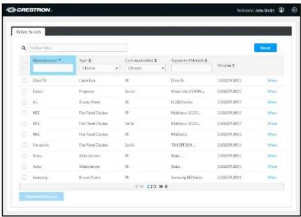
Crestron Certified Drivers Portal Driver Search Page
-
Use the following options to navigate the Crestron Certified Drivers web portal:
-
Type a manufacturer name, device type, communication method, or supported model in the Global Filter text box to filter drivers based on that search term.
- Type a search term in the text box or use the drop-down menu underneath a column heading to filter drivers by the driver information shown in that column. Use the up and down arrows next to the column header to sort the information in that column in alphabetical or reverse alphabetical order, respectively.
- Navigate through the available device drivers by clicking a page number or by
If the driver(s) are uploaded successfully, a notification is displayed indicating that the installation was successful.
CAUTION: Do not activate the new configuration until the notification is displayed indicating that the drivers were loaded successfully. This notification can take several minutes to display if many drivers are uploaded in the same .zip file.
Driver Load Success Message

After the upload completes, a System Notification icon is displayed under the system status message bar.
System Notification Message
The system is currently offline, Activate or Revert configuration.
① System Notification
Click the System Notification icon to open a dialog box that shows the driver manufacturer, model, type, and installation status. The following image shows the installation status of a Sony® XBR7 Series flat panel display.
System Notification Dialog Box
System Notification
Device Management
Navigate to Configure > Device Management to display the Device Management page.
Device Management Page

Use the Device Management page to add a device to the .AV Framework room, to view information about connected devices, and to edit or remove a device.
Observe the following points when managing devices in .AV Framework:
- Certain device classes limit the number of devices that can be added to the system. Once the maximum number of devices have been added to the system, the device class can no longer be selected from the Device Type drop-down menu unless one of its devices is deleted.
Add Devices
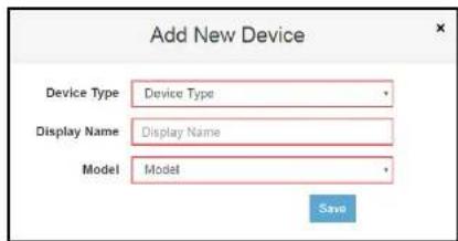
- Click Add Device to add a new device to the .AV Framework room. The Add New Device dialog box opens.
NOTE: For new installations, a compatible switcher device must be added to the system before any other devices can be added. For more information, refer to "Add an A/V Switcher" on page 14.
Add New Device Dialog Box
-
Enter the following information for the chosen device.
-
Device Type: Use the drop-down menu to select the device type from the available options.
• Display Name: Enter a name for the device in the text field. - Model: Use the drop-down menu to select the model of the chosen device from the available options.
NOTE: Certain device types and models require additional information to be entered (such as setting transport control details). Additional drop-down menus and text fields are provided when these device types and/or models are selected.
Adding CEC and Crestron Connected Devices
After a CEC-controlled device or a Crestron Connected ^® device is added, a notice is displayed. The notice for CEC drivers is shown on the following page as an example.
Generic CEC Driver Notice
Generic CEC Driver Notice
Generic CEC is a universal driver provided by Crestron that works with a wide variety of flat panel displays. The specific functionality supported by your device is dependent on the how the CEC specification has been implemented by the device's manufacturer as the CEC specification does not require device manufacturer to implement the entire command set. For a device specific driver, please visit: https://drivers.crestron.io. For more information please contact Crestron True Blue Support at support@crestron.com
Acknowledge
Click Acknowledge to return to the Device Management page.
Adding Flat Panel Displays and Projectors
Flat panel displays and projectors require their drivers to be added to .AV Framework before the device can be selected and added to the system. For more information on adding device drivers, refer to "Drivers," starting on page 34.
NOTE: Certain device drivers require a username and password to initiate control communications. Additional User Name and Password fields are provided in the Add New Device dialog box for these devices. These fields are required or optional depending on the device driver.
Installing XBR7-1 Dialog Box
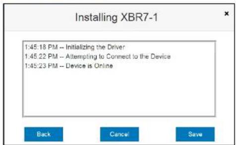
Click Back to return to the Add New Device dialog box. Click Cancel to cancel installing the device driver. Click Save to save the device and return to the Device Management page.
Edit Devices
After a device is added to .AV Framework, it appears in the list of devices on the Device Management page. The display name, device type, device model, transport details, and device status are provided for each device.
- Click the pencil button next to a device to edit the device. The Edit Device dialog box opens.
Devices Page - Edit Device Dialog Box

Editing Flat Panel Displays and Projectors
For flat panel displays and projectors with installed device drivers, a dialog box showing the updated device status is displayed after changes are saved.
Updating XBR7-1 Dialog Box
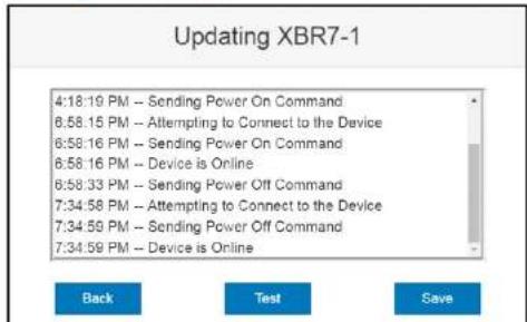
- Click Back to return to the Edit Device dialog box.
- Click Test to display a dialog box for sending test commands to the device. For more information, refer to "Test Devices" below.
- Click Save to save the device and return to the Device Management page.
Test Devices
-
Click the paper and clipboard button next to a flat panel display or a projector to send test commands to the device. A dialog box showing the driver test status is displayed.
-
To send test commands to the device, select a command from the Send Command drop-down menu, and then click Send .AV Framework attempts to send the chosen command to the device.
NOTE: The configuration utility does not provide feedback to confirm if the command was sent successfully. Verify the command is received on the device.
Delete Devices
-
Click the trash can button 📋 next to a device.
-
A warning message is displayed. Click OK to delete the device or Cancel to cancel the deletion.
Inputs/Outputs
Navigate to Configure > A/V Routing to display the Input/Outputs page.
Inputs/Outputs Page
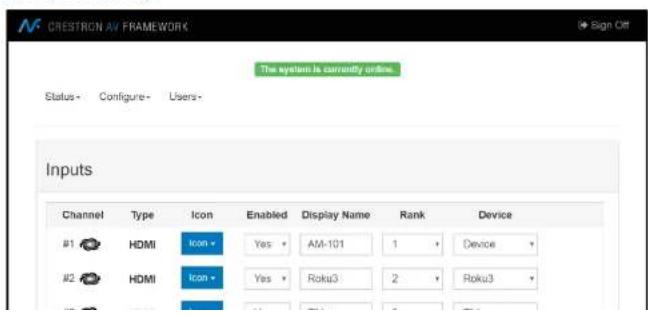
Use the Inputs/Outputs page to configure the input and output channels of the connected switcher device.
The following information can be viewed and configured for each input and output channel unless otherwise noted.
- Channel: This column shows the number of the input or output channel on the switcher device and the chosen icon for that channel.
- Type: This column shows the type of input or output channel (such as HDMI® input or VGA).
- Icon: Use the drop-down menu to select an icon for the channel.
- Enabled: Use the drop-down menu to enable or disable the channel on the .AV Framework system.
• Display Name: Enter the display name of the device connected to the channel. - Rank (Inputs Only): Use the drop-down menu to select a number to determine the order that the input displays appear when selecting a source to present from the touch screen user interface.
- Device (Inputs Only): Use the drop-down menu to select the device connected to the channel. (For more information on adding devices to .AV Framework, refer to page 39.)
Manage Configuration
Navigate to Configure > Configuration Management to display the Manage Configurations page.
Manage Configurations Page

Use the Manage Configurations page to activate new configuration settings or to revert to a prior configuration. The Manage Configurations page also provides controls to download and upload configuration files.
If saved changes have been made to the configuration, click Activate Configuration to activate the new configuration settings or click Revert Configuration to revert to the previous configuration.
The touch screen user interface shows a configuration in progress message.
Configuration in Progress Screen

.AV Framework
System configuration in progress.
Please activate the configuration from the system website to enable the system.
NOTE: If any changes are saved while configuring .AV Framework, the green status bar on the top of the screen turns red and shows a "The system is currently offline, activate or revert configuration" message. Once this message is displayed, any connected devices go offline and cannot be used, and changes must be activated for the devices to go back online. Once the configuration is activated, the status bar turns green and shows a "The
Upload Configuration Dialog Box

The Upload Configuration dialog box provides options for modifying the Crestron Fusion room information that is paired with the configuration:
- Click the Restore radio button to restore the Crestron Fusion room settings that exist in the configuration files.
- Click the Create Room radio button to create a new Crestron Fusion room using the imported configuration settings. Enter the room name in the Crestron Fusion Room Name text field that is displayed.
Click OK to import the configuration files with the selected Crestron Fusion room settings or click Cancel to cancel the import.
Users Menu
The Users menu provides a selection for adding, editing, and deleting users in the .AV Framework system.
Navigate to Users > Manage to display the Manage Users page.
Manage Users Page
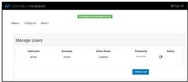
Use the Manage Users page to manage, add, and edit .AV Framework users. The following information is provided for each user:
- Username: The username created for the user
NOTE: The administrative account for .AV Framework is specified by the username "admin." This username cannot be changed.
- Surname: The user's last name
• Given Name: The user's first name
To delete a user:
- Click the trashcan button 📋 in the Action column for that user. A warning message is displayed.
- Click OK to delete the user or Cancel to cancel the deletion.
NOTE: The "admin" account cannot be deleted.
Operation
The .AV Framework touch screen user interface provides a collection of room scheduling and BYOD (bring your own device) presentation capabilities. The various screens that comprise the user interface are described in the sections that follow.
Display Overview
Each screen in the .AV Framework touch screen project provides the following features:
- A status bar that provides the room name and the time and date (set using the web-based configuration utility).
- A square status icon next to the room name that turns red when the room is reserved and blue if the room is available (if room scheduling is enabled).
- A footer bar that provides buttons for navigating and controlling the system volume (if supported by the display device or the external amplifier).
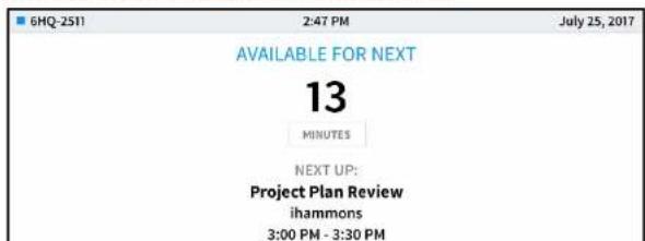
The following image shows a typical home screen (the project's default page) with the status bar and footer bar.
Home Screen (Room Available) - Status and Footer Bars
Volume Control Buttons
| The microphone button mutes or unmutes the device microphone. | |
| The mute button mutes or unmutes the device volume. | |
| - | The volume lower button lowers the device volume incrementally. |
| + | The volume raise button raises the device volume incrementally. |
NOTE: The volume control buttons and the volume bar are visible only if an external amplifier is enabled and connected to the .AV Framework room (set using the web-based configuration utility) or if the display device output supports volume control. For more information, refer to "System" on page 26.
Home Screen Overview
The home screen is the default screen of the touch screen project. The home screen indicates whether the associated room is either available or reserved for meetings (if .AV Framework is connected to a scheduling calendar):
- If the room is available, the home screen allows an ad hoc meeting to be reserved from the touch screen.
- If the room is reserved, the home screen shows current meeting information and the time remaining in the meeting.
If .AV Framework is not connected to a scheduling calendar, the home screen shows a custom logo (if enabled) or the date and time and provides a button that is used to switch to the system's default route.
The home screen may be accessed at any time by touching the home (button on the footer bar.
No Scheduling Calendar Connected
If .AV Framework is not connected to a scheduling calendar, the home screen provides
Home Screen (No Scheduling Calendar Connected)

NOTE: If a custom help page image has been configured for the touch screen project, it will be displayed instead of the default help overlay when the Help button is tapped. For more information, refer to "Touch Screen Custom Graphics" on page 30.
Room Available
If .AV Framework is connected to a scheduling calendar and the room is available, the home screen provides the following information:
• The time remaining (in minutes) until the next scheduled meeting occurs
• The name, organizer, and duration of the next scheduled meeting
- A RESERVE NOW button that allows an ad hoc meeting to be scheduled through the next session.
Home Screen (Room Available)

If the room is available for the rest of the day, the home screen provides the following information:
- A RESERVE NOW button that allows an ad hoc meeting to be scheduled through the touch screen
• A Help button that provides more information on the functions of this screen
The image below shows a typical home screen when the room is available for the rest of the day.
Home Screen (Room Available for the Rest of the Day)
| 6HQ-2511 | 2:14 PM | July 25, 2017 |
Room Reserved
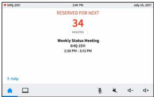
If the room is not available, the home screen provides the following information:
• The time remaining (in minutes) until the current meeting ends
• The name, organizer, and duration of the current meeting
• The duration and name of the next scheduled meeting
• A Help button that provides more information on the functions of this screen
The image on the following page shows a typical home screen when the room is reserved.
Home Screen (Room Reserved)
Reserve a Meeting from the Home Screen
New Meeting Screen

-
Tap one of the available meeting end times to set the duration of the meeting. The room can be reserved for up to three lengths:
-
Until the current half hour interval ends (If the current time is 10:17AM, the end time for this option is 10:30AM.)
- Until the current half hour interval ends plus 30 minutes (If the current time is 10:17AM, the end time for this option is 11:00AM.)
- Until the current half hour interval ends plus 60 minutes (If the current time is 10:17AM, the end time for this option is 11:30AM.)
NOTE: These options are available only if a meeting is not already scheduled during that timeframe.
System Info Screen

To exit the System Info screen and return to the home screen, tap the x button on the top right of the screen.
Present a Source Screen Overview
The Present a Source screen allows content to be routed from a connected device to the main display in the room.
The Present a Source screen appears as shown in the following image.
Present a Source Screen

Select one of the available presentation options to route the selected source to the main display. The source is controlled directly through the touch screen project.
• Each available source has a green or red icon in the top right corner of its background tile.
- A green icon indicates that video signal is present for that source
Now Presenting Screen - HDMI Source
When a source connected by HDMI (such as a laptop) is selected, the following screen is displayed.
Present Screen - HDMI Source
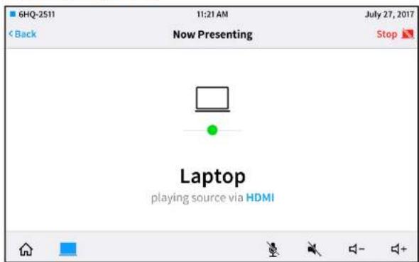
The Now Presenting screen for HDMI provides the input name and connection type. The circle icon in the center of the screen turns green if the source is connected and turns red if the source is disconnected.
Tap Stop on the top right of the screen to disconnect from the HDMI source.
Tap BACK to return to the Present a Source screen. Pressing BACK does not disconnect the source.
Connect to AirMedia Screen
When an AirMedia® presentation gateway source is selected and the wireless connection has not already been established, the following screen is displayed.
Connect to AirMedia Screen

The Connect to AirMedia screen provides instructions for connecting to the AirMedia device over a wireless network. Once this connection has been established, AirMedia can be selected as a presentation source.
If the connection code has been disabled, a version of the Connect to AirMedia screen is displayed that omits this step. For more information on disabling the connection code, refer to the AirMedia device's documentation at www.crestron.com/manuals.
Connect to AirMedia Screen - Connection Code Disabled

Press BACK to return to the Present a Source screen.
Now Presenting Screen - AirMedia Source
When an AirMedia source is selected (once a wireless connection has been established), the following screen is displayed.
Present Screen - AirMedia Source

Press Stop on the top right of the screen to disconnect from the AirMedia source.
Press BACK to return to the Present a Source screen. (Pressing BACK does not disconnect the source.)
Now Presenting Screen - Other Source Devices
The touch screen project provides custom Now Presenting screens for various source devices, such as cable TV receivers and video servers, which include controls that are specific to the device and that are mapped via the device driver.
To view more examples of Now Presenting screens for other source devices, refer to the .AV Framework DMPS UI Guide at www.crestron.com/manuals.
Appendix A: Interface Setup
This appendix provides information on how to connect various supported interfaces to the Crestron Virtual Control server.
Connection Overview
To connect Ethernet devices, use one of the following methods:
NOTE: A device must only be assigned to one room unless it is a shared device or a touch screen device.
- Use the Connect Request method in Crestron Toolbox™ software to specify the Room ID of the room that is running the .AV Framework program. For more information, refer to the embedded Crestron Virtual Control help file.
NOTE: The latest version of Crestron Toolbox and the latest device firmware are required to use the Connect Request method.
- Set the IP table of the Ethernet device to point to the IP address or hostname of the Crestron Virtual Control server via the device setup pages (if available) or via the IP table dialog box in Crestron Toolbox software.
Devices can also be associated with rooms manually. For more information, refer to the embedded Crestron Virtual Control help file by clicking the help button ? on the top right of the configuration utility.
If a device with older firmware is not on the same subnet as the Crestron Virtual Control server, it cannot be discovered by the server. As a workaround, the admin can create a "device_resolution.cfg" file that contains the FQDN (fully qualified domain name), MAC address, and device type for any cross-subnet devices with older firmware. The Crestron Virtual Control service reads this file on startup and then once every hour while the service is running.
TSW Series Touch Screens
Connect a supported Crestron TSW series touch screen (TSW-752, TSW-1052, TSW-760, or TSW-1060) to the .AV Framework room to control room scheduling and source selection functions from the touch screen.
NOTE: The .AV Framework touch screen project must be loaded on the touch screen prior to operation.
To connect a TSW series touch screen:
NOTE: Ethernet setup screens for the TSW-760 and TSW-1060 are shown for this procedure. Similar screens are used to connect the TSW-752 and TSW-1052.
- On the Setup screen, tap IP Table Setup to display the Ethernet Setup - IP Table screen.
Ethernet Setup - IP Table Screen

Ethernet Setup - IP Table Screen

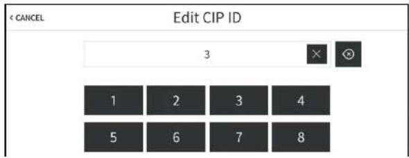
- Tap the text field below CIP ID to display the Edit CIP ID on-screen hex keypad.
Edit CIP ID - On-Screen Hex Keypad
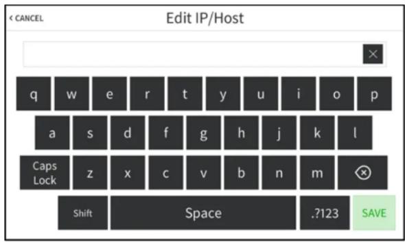
Edit IP/Host - On-Screen Keyboard
-
Use the keyboard to enter the IP address or hostname of the Crestron Virtual Control server.
-
Tap the clear button (✗) in the text field to clear any previous entry.
- Tap the delete button ( Ⓤ ) to delete the last digit.
-
Tap SAVE to save a new entry or tap < CANCEL to discard any changes. The display returns to the Ethernet Setup - IP Table screen.
-
On the Ethernet Setup - IP Table screen, tap SAVE to save the current entry.
NOTE: A touch screen that is associated with a room manually is not able to load touch screen projects from the Crestron Virtual Control server. Use the Connect Request method in Crestron Toolbox to ensure that the touch screen project is loaded when the touch screen comes online.
XPanel
Connect to XPanel to configure a virtual touch screen project for testing and control.
To configure a virtual touch screen project with XPanel:
-
Install XPanel by running Crestron XPanel installer.air (for Macintosh® systems) or Crestron XPanel installer.exe (for Windows® systems). These installer applications can be downloaded from www.crestron.com/software.
-
Load the touch screen project .vtz file in the XPanel application.
-
Open the configuration dialog box by selecting Options > Host Settings.
-
Enter the IP address of the Crestron Virtual Control server running the .AV Framework program.
-
Enter the IP ID for connecting to the Crestron Virtual Control server.
-
Click Connect.
Configuration Dialog Box

The touch screen project can also be displayed and tested using the .AV Framework program's built-in web XPanel interface.
NOTE: A touch screen device must be added to the .AV Framework room with IP ID 04 to
Status Tab - Rooms
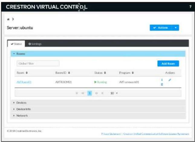
- Click the information button i under the Actions column for the room that is running the .AV Framework program. The Status > Details page for the room is displayed.
Status Tab - Details

Web XPanel Interface
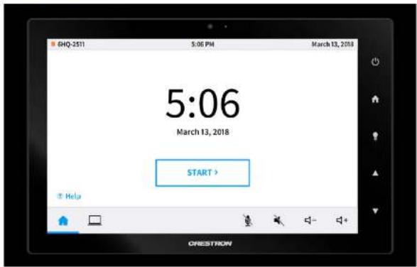
All touch screen project functions and screens can be tested through the web XPanel interface. Additionally, the virtual touch screen hard buttons (except for the center lightbulb button) provide the same functionality as a physical touch screen.
AM-100/AM-101
Connect a Crestron AM-100 or AM-101 AirMedia presentation gateway to the .AV Framework room to present content wirelessly on a display output.
To connect an AM-100 or AM-101:
- Use a web browser to connect to the AirMedia device's IP address.
- Click Device Administration to display the login page.
- Log in to the configuration utility. The default password is "admin."
- Select Crestron Services Setup from the column on the left side of the page.
Device Administration - Crestron Services Setup
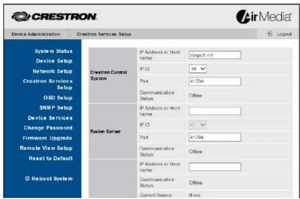
- Set an IP ID used to connect to the Crestron Virtual Control server.
- Set the Port to 41794.
- Click Apply.
MP-B10/MP-B20
Connect a Crestron MP-B10 or MP-B20 media presentation button panel to the .AV Framework room in place of a touch screen for device routing and source control.
NOTE: Observe the following points when connecting an MP-B10 or MP-B20:
- No more than two button panels can be added to the same configuration.
- If .AV Framework is powered off from the button panel, power on functionality is disabled until after a 30-second period has elapsed.
- If .AV Framework is controlled using a button panel and a connected display device requires a warm-up or cool-down period, button panel functions are disabled until the warm-up or cool-down period has completed.
The scroll wheel on the MP-B10 adjusts volume level.
The .AV Framework configuration utility also provides screens that can be used to configure each button individually. When adding or editing a button panel, click Configure Buttons.
Edit Device Dialog Box - Button Panel

Configure Buttons Dialog Box - MP-B20
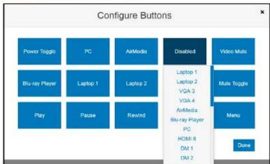
Each button on the button panel can be configured by clicking its respective button in the Configure Buttons dialog box. A drop-down menu is displayed when a button is clicked.
Select one of the switcher device's input channels from the drop-down menu to map that input to the button or select one of the provided functions to map that function to the button.
NOTE: When using the MP-B20 for source control, the device's 5-way navigation pad is only functional when an appropriate source device input, such as a Blu-ray Disc player or a media server, is selected. Each button on the navigation pad is mapped to the appropriate function on the selected device's menu.
The default input names for the switcher device inputs can be customized in the configuration utility. For more information, refer to "Inputs/Outputs" on page 43.
Crestron Fusion
Connect to Crestron Fusion software to monitor and control basic room data, system power, source selection, and room scheduling.
Connect to Crestron Fusion
To connect with Crestron Fusion, use the following procedure:
- Log in to the Crestron Fusion server.
- From the Crestron Fusion header tab, click Open.
Crestron Fusion Cloud Header Tab

- From the pull-down tab, click Setup.
Pull-Down Tab
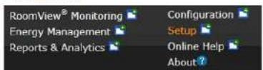
- Click the + symbol next to Root node to expand the tree. Click the Rooms node to select the node.
Root Node

Add - Room Dialog Box

- From the drop-down list, make a selection and then click OK. The Add Room to 'Rooms' dialog box opens with the Room Details tab selected.
Room Details Tab
![Author Name Form Details Address Address Name Source Description Server Group Database Session Time Zone: UTC 00:00 System Time (12.4 Canada) @Current UFC WebCam UFC Use Web Design Coordinate Please use WebCam to navigate the WebCam from WebCam to WebCam User(s) [12.4 Canada] to access WebCam. Location Send to Email Cancel](/content/2026/05/926742/images/03132c3a7e483dc645d98fba322e083194d6059a1b88baa21cb59656b5508e1e.jpg)
- Enter information into the required fields as indicated by the red asterisks. Enter optional information as desired.
-
Click the Scheduling Details tab
-
In the Server Access field, select the RoomView® scheduling application.
NOTE: The user can change to another scheduling calendar later.
- Click the Processors tab, and then click Add.
Processors Tab

The Add Processor to 'Room' dialog box opens.
Add Processor to 'Room' Dialog Box
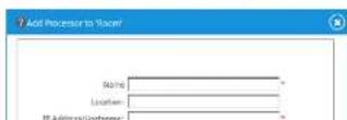
- Click the Discover Symbols check box.
NOTE: If the Discover Symbols check box is selected in the Add Processor to 'Room' dialog box and the control program symbol being used is version 7.2 or higher, the Symbol Discover feature automatically imports the symbol information into the Crestron Fusion database.
- Click the Use SSL check box if Discover Symbols was selected and if the processor is configured for Secure CTP Toolbox connections only.
NOTE: In the Crestron SystemBuilder™ and D3 Pro® platforms, the Symbol Discover feature is not supported on symbols below version 7.2.
- Click Save & Close.
NOTE: Steps 15 through 21 are not necessary if the Discover Symbols check box is selected in the Add Processor to 'Room' dialog box.
- Click the + symbol next to the processor name to add, edit, or delete a symbol.
Add, Edit, or Delete Symbol

- Click Add. The Add Symbol to 'New Processor' dialog box opens with the Symbol Details tab selected.
Symbol Details Tab

- Click Save & Close to save the symbol; click Save & Close again to save the room.
NOTE: To associate the room with a node other than the selected Rooms node, click and drag the new room to that node. The room is now associated with the new node.
Room Control and Monitoring
Room monitoring and control in Crestron Fusion use the following attributes.
System Monitors (Read Only)
| TYPE FUNCTION | |
| Serial | Crestron Fusion Error Message |
| Serial | Crestron Fusion Log Text |
| Serial | Crestron Fusion Device Usage |
Controller (Read Only)
| TYPE FUNCTION |
| Serial Name |
| Serial Hostname |
| Serial IP Address |
| Serial Subnet Mask |
| Serial Default Router |
| Digital Connected |
Environment (Read Only)
| TYPE FUNCTION |
| Analog System Volume |
Switch (Read Only)
| TYPE FUNCTION |
| Serial Display Name |
| Serial Model |
| Serial Input Channels Enabled |
| Serial Output Channels Enabled |
| Serial Input 1 Name |
| Serial Input 2 Name |
| Serial Input 3 Name |
| Serial Input 4 Name |
| Serial Input 5 Name |
| Serial Input 6 Name |
| Serial Input 7 Name |
| Serial Input 8 Name |
| Serial Input 9 Name |
| Serial Input 10 Name |
| Serial Output 1 Name |
| Serial Output 2 Name |
| Serial Output 3 Name |
| Digital Connected |
Monitor the assets connected to the room with the following attributes:
TSW-752/TSW-1052 (Read Only)
| TYPE FUNCTION |
| Digital Connected |
| TSW-760/TSW-1060 (Read Only) |
AM-100/AM-101 (Read Only)
TYPE FUNCTION
Digital Connected
AM-200/AM-300 (Read Only)
TYPE FUNCTION
Digital Connected
MPB-10/MP-B20 (Read Only)
TYPE FUNCTION
Digital Connected
Cable TV Receiver (Read Only)
TYPE FUNCTION
Digital Connected
Projector (Read Only)
TYPE FUNCTION
Digital Connected
Video Server (Read Only)
TYPE FUNCTION
Digital Connected
Appendix B: Device Configuration
Each device that is compatible with .AV Framework for Crestron Virtual Control has specific fields that must be configured when the device is added to the system.
The tables below provide information about the various configuration fields associated with each device class.
AirMedia
Add New Device Fields - AirMedia
| FIELD DESCRIPTION SUPPORTED VALUES | ||
| Display Name | The user defined AirMedia device display name | |
| Model | The AirMedia device model name | AM-100, AM-101, AM-200, AM-300 |
| Control | The transport method used for device control | IP ID |
| IP ID | The IP ID used to connect the AirMedia device to the server | |
NOTE: The AM-200 and AM-300 can be added to the system as a source device or as an A/V switcher device. To add the AM-200 or AM-300 as an A/V switcher, refer to "Add an A/V Switcher" on page 14.
Blu-ray™ Player
Add New Device Fields - Blu-ray™ Player
| Display Name | The user-defined Blu-ray player display name | |
| Model | The Blu-ray player device model | [Any supported video server] |
| Control | The transport method used for device control | IP |
Button Panel
Add New Device Fields - Button Panel
FIELD DESCRIPTION SUPPORTED VALUES
| Display Name | The user-defined button panel display name | |
| Model | The button panel model name | MP-B10 IPID, MP-B10 Cresnet Bus ^1 ,MP-B20 IPID, MP-B10 Cresnet Bus ^1 |
| Control | The transport method used for device control | IP ID, Cresnet Bus |
| IP ID ^2 | The IP ID used to connect the button panel to the server | |
| Gateway Bus ^3 | The bus that the button panel is connected to on the Cresnet gateway |
^1 This value is provided only when a Cresnet gateway has been added to the system.
^2 This field is provided when MP-B10 IPID or MP-B20 IPID is selected for Model.
^3 This field is provided when MP-B10 Cresnet Bus or MP-B20 Cresnet Bus is selected for Model.
NOTE: The Add New Device dialog box also provides a Configure Buttons selection when Button Panel is selected as the device type, which can be used to configure individual buttons on the button panel. For more information, refer to "MP-B10/MP-B20" on page 69.
Cable TV
Add New Device Fields - Cable TV
FIELD DESCRIPTION SUPPORTED VALUES
| Display Name | The user-defined cable TV receiver display name | |
| Model | The cable TV receiver model name | [Any supported cable TV receiver] |
| Control | The transport method used for device control | IP |
| IP | The cable TV receiver IP address on the network | |
| Port | The cable TV receiver web port | |
Crestron IO
Add New Device Fields - Crestron IO
| FIELD DESCRIPTION SUPPORTED VALUES | ||
| Display Name | The user-defined Crestron IO device name | |
| Model | The Crestron IO device model name | C2N-IO Bus1, CEN-IO-COM-102, CEN-IO-IR-104, CEN-IO-RY-104 |
| Control | The transport method used for device control | IP ID, Cresnet Bus |
| IP ID2 | The IP ID used to connect the Crestron IO device to the server | |
| Gateway Bus3 | The bus that the Crestron IO device is connected to on the Cresnet gateway | |
^1 This value is provided only when a Cresnet gateway has been added to the system.
^2 This field is provided when CEN-IO-COM-102, CEN-IO-IR-104, or CEN-IO-RY-104 is selected for Model.
^3 This field is provided when C2N-IO Bus is selected for Model.
DigitalMedia Transmitter
Add New Device Fields - DigitalMedia Transmitter
| FIELD DESCRIPTION SUPPORTED VALUES | ||
| Display Name | The user defined DigitalMedia transmitter name | |
| Model | The DigitalMedia transmitter model name | DM-TX-201-C1,DM-TX-401-C1,DM-TX-4K-202-C1,DM-TX-4K-302-C1 |
| Control | The transport method used for device control | IP ID |
| IP ID | The IP ID of the DigitalMedia transmitter | |
^1 These models are only available if an AM-300 is selected as the A/V switcher for the system.
Flat Panel Display
Add New Device Fields - Flat Panel Display
| FIELD DESCRIPTION SUPPORTED VALUES | ||
| Display Name | The user-defined display name of the flat panel display | |
| Model | The flat panel display model name | [Any supported flat panel display] |
| Control | The transport method used for device control | CEC, IP ID, IP, Serial |
| Default Input ^1 | The default input of the flat panel display in the system | [Any available input of the appropriate type in the system] |
| Communications Part ^2,3 | The device port that controls the flat panel display | [Any unused communication port for the selected transport method in the system] |
| IP ID ^1 | The IP ID used to connect the flat panel display to the server | |
| IP ^4 | The IP address of the flat panel display on the network | |
| Port ^4 | The flat panel display web port | |
| Channel ^4,5 | The flat panel display Wi-Fi ^6 network channel | |
| Warm Up Time ^8,7 | The duration that a "warming up" message is displayed on the .AV Framework user interface after the display is powered on, in seconds | [Minimum value is the default defined by the device driver; maximum value is 300 seconds] |
| Cool Down Time ^5,7 | The duration that a "cooling down" message is displayed on the .AV Framework user interface after the display is powered off, in seconds | [Minimum value is the default defined by the device driver; maximum value is 300 seconds] |
| User Name ^8 | The username (required or optional) for initiating device control communications | |
| Password ^8 | The password (required or optional) for initiating device control communications | |
This field is provided when a flat panel display that uses a transport method for device control is selected.
^2 This field is provided when a CEC-controlled flat panel display is selected for Model.
^8 This field is provided when a Crestron Connected controlled flat panel display is selected for Model.
Some or all these fields are provided when an IP-controlled flat panel display is selected for Model and IP is selected for Control.
Occupancy Sensor
Add New Device Fields - Occupancy Sensor
| FIELD DESCRIPTION SUPPORTED VALUES | ||
| Display Name | The user-defined occupancy sensor name | |
| Model | The occupancy sensor model name | GLS-ODT-C-CN Bus ^1 , GLS-OIR-C-CN Bus ^1 |
| Control | The transport method used for device control | Cresnet Bus |
| Gateway Bus | The bus that the occupancy sensor is connected to on the Cresnet gateway | |
| Use Sensor Timeout | Sets whether system timeout is determined by Yes, No the occupancy sensor device (For example, if Yes is selected, the system times out if no occupancy is detected in a room) | |
| Timeout Minutes ^2 | The duration in minutes that it takes for the system to time out if sensor timeout is not used | |
| Turn System On | Sets whether the .AV Framework system turns Yes, No on if motion is detected by the occupancy sensor device | |
| Turn System Off | Sets whether the .AV Framework system turns Yes, No off if no occupancy is detected by the occupancy sensor device | |
| Route Default Video | Sets whether default video is routed when the Yes, No occupancy sensor turns on the .AV Framework system. | |
This value is provided only when a Cresnet gateway has been added to the system.
^2 This field is provided when No is selected for Use Sensor Timeout.
Projector
Add New Device Fields - Projector
| FIELD DESCRIPTION SUPPORTED VALUES | ||
| Display Name | The user-defined projector display name | |
| Model | The projector model name | [Any supported projector] |
| Control | The transport method used for device control | IP ID, IP, Serial |
| Default Input | The default input of the projector in the system | [Any available input of the appropriate type in the system] |
| IP ID^1 | The IP ID used to connect the projector to the server | |
| IP^2 | The IP address of the projector on the network | |
| Part^3 | The projector web port | |
| Communications Part^3 | The device port that controls the projector | [Any unused communication port for the selected transport method in the system] |
| Warm Up Time ^4,5 | The duration that a "warming up" message is displayed on the .AV Framework user interface after the projector is powered on, in seconds | [Minimum value is the default defined by the device driver; maximum value is 300 seconds] |
| Cool Down Time^1,5 | The duration that a "cooling down" message is displayed on the .AV Framework user interface after the projector is powered off, in seconds | [Minimum value is the default defined by the device driver; maximum value is 300 seconds] |
| User Name^6 | The username (required or optional) for initiating device control communications | |
| Password^7 | The password (required or optional) for initiating device control communications | |
^1 This field is provided when IP ID is selected for Control.
^2 These fields are provided when IP is selected for Control.
^3 This field is provided when Serial is selected for Control.
^2 All controls on the user interface are temporarily locked out until the message times out.
^6 These fields are provided only if the projector driver supports this functionality.
^6 These fields are provided when a device driver for a projector requires a username and password to initiate control communications.
Touch Screen
Add New Device Fields - Touch Screen
| FIELD DESCRIPTION SUPPORTED VALUES | ||
| Display Name | The user-defined touch screen display name | |
| Model | The touch screen model name | TSW-1052, TSW-1060, TSW-752, TSW-760, Webx |
| Control | The transport method used for device control | IP ID |
| IP ID | The IP ID used to connect the touch screen to the server | |
NOTE: Select Webx using the Model drop-down menu when configuring a virtual touch screen project with the .AV Framework program's built-in XPanel interface. For more information, refer to "Xpanel" on page 65.
Video Server
Add New Device Fields - Cable TV
| FIELD DESCRIPTION SUPPORTED VALUES | ||
| Display Name | The user-defined video server device display name | |
| Model | The video server device model | [Any supported video server] |
| Control | The transport method used for device control | CEC, IP |
| Communications Port1 | The device port that controls the video server device | [Any unused communication port for the selected transport method in the system] |
| IP2 | The video server device IP address on the network | |
| Port2 | The video server device web port | |
^1 This field is provided when CEC is selected for Control.
This page is intentionally left blank.
- Contents
- .AV Framework™ Software for Crestron Virtual Control Software
- Introduction
- Product Features
- Setup
- Load the Program Files
- Add .AV Framework Rooms
- Generate an Authentication Token
- Access the Configuration Utility
- Click Sign In.
- Add an A/V Switcher
- Add New Devices
- Configuration
- Navigate the Configuration Utility
- Equipment
- AVF Log
- AVF Log Page
- Configure Menu
- Warning Message
- System Setup
- NOTES:
- Device Management
- Add Devices
- Test Devices
- Delete Devices
- Inputs/Outputs
- Inputs/Outputs Page
- Manage Configuration
- Users Menu
- Operation
- Display Overview
- Home Screen Overview
- No Scheduling Calendar Connected
- Room Available
- Room Reserved
- Present a Source Screen Overview
- Connect to AirMedia Screen
- Now Presenting Screen - Other Source Devices
- Appendix A: Interface Setup
- Connection Overview
- TSW Series Touch Screens
- XPanel
- AM-100/AM-101
- MP-B10/MP-B20
- Crestron Fusion
- Connect to Crestron Fusion
- Room Control and Monitoring
- Appendix B: Device Configuration
- AirMedia
- Blu-ray™ Player
- Button Panel
- Cable TV
- Crestron IO
- DigitalMedia Transmitter
- Flat Panel Display
- Occupancy Sensor
- Projector
- Touch Screen
- Video Server
Brand : Crestron
Model : VC-4-CORE
Category : Software