
FirePro MXRT-5400 - Video card Barco - Free user manual and instructions
Find the device manual for free FirePro MXRT-5400 Barco in PDF.


| Product Type | Professional Graphics Card |
| Model | FirePro MXRT-5400 |
| Brand | Barco |
| GPU Architecture | AMD FirePro (based on GCN architecture) |
| Memory | 4 GB GDDR5 |
| Memory Interface | 256-bit |
| Output Ports | 2x DisplayPort 1.2, 1x DVI-I |
| Maximum Resolution | 4096x2160 at 60 Hz per display |
| Form Factor | PCI Express 3.0 x16, full-height, dual-slot |
| Dimensions (L x H) | 267 mm x 111 mm |
| Power Consumption | Up to 150 W |
| Power Connector | 1x 6-pin PCIe |
| Cooling | Active fan, single axial fan |
| Operating Temperature | 0°C to 40°C |
| Certifications | FCC, CE, RoHS |
| Supported APIs | DirectX 12, OpenGL 4.5, OpenCL 2.0 |
| Multi-Monitor Support | Up to 4 displays via MST hub |
| Intended Use | Medical imaging, CAD, DCC |
| Maintenance | Periodic dust cleaning; avoid liquids |
| Safety Precautions | Install in grounded slot; ensure adequate ventilation |
| Spare Parts | Replacement fans available; contact Barco support |
| Manual Language | English (EN) – PDF available |
Frequently Asked Questions - FirePro MXRT-5400 Barco
User questions about FirePro MXRT-5400 Barco
0 question about this device. Answer the ones you know or ask your own.
Ask a new question about this device
Download the instructions for your Video card in PDF format for free! Find your manual FirePro MXRT-5400 - Barco and take your electronic device back in hand. On this page are published all the documents necessary for the use of your device. FirePro MXRT-5400 by Barco.
USER MANUAL FirePro MXRT-5400 Barco
natural_image
Close-up of a FirePro 3D graphics card with red circuit board and NVIDIA logo (no readable text beyond branding)UserGuide
Windows7andWindows8.1
Table of contents
TABLEOFCONTENTS
- Welcome! 3
1.1 About the product 3
1.2 What's in the box....3
- Display Controller installation....5
2.1 Which Display Controller? 5
2.2 Installing a Barco Display Controller 5
2.3 Installation procedure....6
2.4 Connecting your Barco Displays 7
- Dongles 9
3.1 Passive Single-Link Dongle 9
3.2 Active Single-Link Dongle....9
3.3 Dual-Link Dongle....10
3.4 Common cases....11
4.Driver and software installation....23
4.1 Driver and software installation prerequisites 23
4.2 Installing the Barco MXRT drivers and software 23
4.3 After installation 25
4.4 Silent installation of drivers and software....28
- Configuring Windows ...... 31
5.1 Configuring SingleView 31
5.2 Configuring Barco Displays with the Windows Display Control Panel....31
5.3 Configuring software rotation 31
- ConferenceCloneView....33
6.1 What is Conference CloneView? 33
6.2 Configuration 33
6.3 Notification icon 34
6.4 Tools available on the cloned display 35
- Important information....37
7 1 Safety information 27
Table of contents
1.WELCOME!
1.1 About the product
DisplayController
ThankyouforchoosingthisBarcoDisplayController!
Barco'sstate-of-the-artDisplayControllersdelivertheperformance,qualityandstabilityr requiredforto-day'sadvancedmedicalimagingapplications. Thepowerfulboardsensureultra-fastandsmoothimage loading,roamingandmanipulationofimagesineveryresolution.
UsetheinstructionsinthisguidetoinstallyourBarcoDisplayController.
1.2 What'sinthebox
Contents
YourBarcoDisplayControllercomeswith:
•ThisBarcoDisplayControllerUserGuide
•2Single-LinkDonglesareincludedwiththeMXRT-4500, MXRT-5400, MXRT-5500, MXRT-7400& MXRT-7500.
• 1 Single-Link Dongle and 1 low-profile bracket are included with the MXRT-2400 & MXRT-2500.
• 1 DMS-59-to-DVI adapter cable and 1 low-profile bracket are included with the MXRT-1450 & MXRT-1451.

Keep your original packaging. It is designed for this Display Controller and is the ideal protection during transport and storage.
- Welcome!
2.DISPLAYCONTROLLERINSTALLATION
2.1 Which DisplayController?
DisplayControllerrange
YourBarcomedicaldisplayiscompatiblewithalargerangeofBarcoandnon-BarcoDisplayController boards. Dependingontheorderdetails, thedisplaycanbedeliveredwithorwithoutaDisplayController.
If you are installing a Barco Display Controller, please follow the installation instructions in this section. If you are installing an on-Barcodisplay controller, please consult its corresponding document
2.2 InstallingaBarcoDisplayController
Guidance
ThischapterwillguideyouthroughthephysicalinstallationofaBarcoDisplayControllerforyourdisplay system.

WARNING: Wear a grounded, protective ESD strap when handling or during installation of the DisplayController. ElectrostaticchargescandamagetheDisplayController.
Overview
Prior to installing the Barco Display Controller(s) for your Barco Display System in your workstation, please takeafewminutestofamiliarizeyourselfwiththeDisplayController(s)andthePCIeslots.
Types of Display Controllers for Barco Display Systems
The following models of Base Display Controllers are available for your display system. Please check
2. Display Controller installation
WhichPCleslottouse
The table aboveliststhevariousDisplayControllermodel(s) available for your BarcoDisplaySystem and the recommended PCIe slot to use for optimum performance. The figure below shows the different types of PCIe slot that can be used.
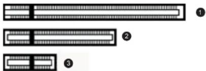
Image2-1 ExamplesofPCleslots
1 x16slot
2 x8slot
③ x1slot
2.3 Installation procedure
Howtoinstall
The following instructions will take you step by step through the installation of the BarcoDisplayController(s) for your BarcoDisplaySystem.
-
If you are not going to use your old Controller, uninstall its drivers and software.
Warning: Wear a grounded, protective ESD strap when handling or during installation of the Display Controller. ElectrostaticchargescandamagetheDisplayController. -
Tumoffthecomputer, display(s), and other peripheral devices.
-
Unplugthecomputer's powercordanddisconnectallcablesfromthebackofyourcomputer. Warning: Wait approximately 20 seconds after unplugging the power cord before disconnecting a peripheralomovinaaccomponentfromthemotherboardtoavoidpossibledamadetothe
-
Display Controller installation
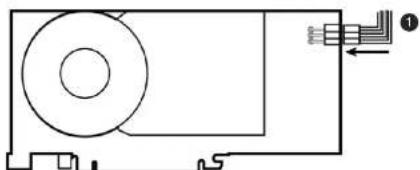
natural_image
Pure technical diagram of a mechanical component with no text, numbers, or symbolsImage2-2 PowerconnectionfortheMXRT-7400&MXRT-7500controllers
6-pingraphicscontrollerpowercable
- Screw in or firmly fasten the Display Controller. Replace and secure the computer cover.
2.4 Connecting your Barco Displays

For detailed description of the display installation and signal connection, pleaserefer to the Display User Guide.
IO-PanelfortheBarcoMXRT-1450&MXRT-1451
natural_image
Front view of a computer RAM card showing D-sub port and drive slots (no text or symbols)2. Display Controller installation
IO-PanelfortheBarcoMXRT-5450&MXRT-5550
natural_image
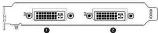
Back panel diagram showing two D-sub port connectors with labeled pins (no text or symbols beyond labels)Image2-5 MXRT-5450&MXRT-5550
1 Head1-DVI-ICConnection
2 Head2-DVI-IPConnection
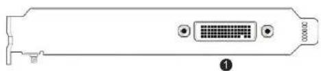
IO-PanelfortheBarcoMXRT-4500, MXRT-5400, MXRT-5500&MXRT-7400
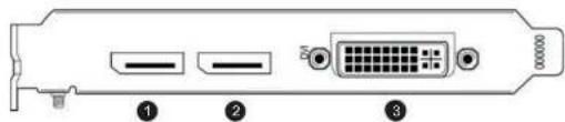
Image2-6 MXRT-4500, MXRT-5400, MXRT-5500 & MXRT-7400
1 DisplayPort#1
② DisplayPort#2
③ DVI-I
IO-PanelfortheBarcoMXRT-7500

3. Dongles
3.DONGLES

BarcodonglesarespeciallydesignedtoallowBarcoDisplayControllerswithaDisplay-PortoutputtobeconnectedwithadisplaywithDVinput.

Ifvideocableconversionisnotrequired,youmaybypassthissection.
3.1 Passive Single-Link Dongle
PassiveSingle-Link
ThepassiveSingle-LinkDongleallowsyoutoconnectadisplay'sDVinputtotheDisplayPortoutputof yourBarcoDisplayController.ItiscompatiblewithallBarcograyscaledisplaysandupto2MPcolor models.Forcolordisplaysof3MPandgreaterresolutions,theDual-L inkDongleisnecessary.

AllBarcoDisplayControllerscompatiblewiththeDisplayPortinterfacecomewithaSingle-LinkDonglebydefault.

natural_image
Close-up of a USB cable connector with two connectors labeled ① and ② (no text or symbols on the cable itself)3. Dongles
3.3 Dual-LinkDongle
Dual-Link
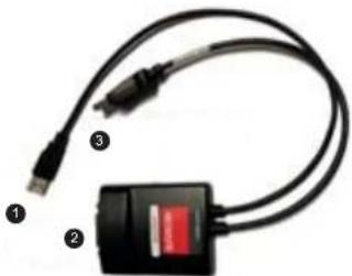
TheactiveDual-LinkDonglealsoconvertsDisplayPortinputsignalstoDVIoutputsignals. However, unlike thepassiveSingle-Linkdongle, theDual-Linkdongleallowshigherresolutions (greater than 1920x1200) oncolordisplays.

WARNING: A Dual-Link DVI cable must be used to connect your display's DVI connector with the DVI connector on the Dual-Link Dongle.

TheDual-Linkdongleisorderedseparately.
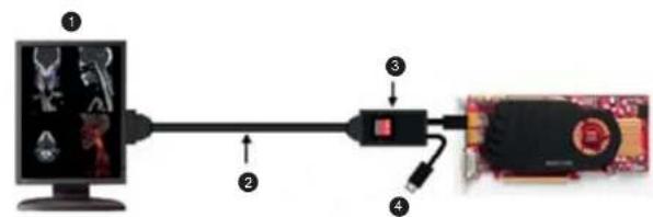
Usethefollowingstepstoinstallthedongle:
- ConnecttheDisplayPortendoftheconnectortotheDisplayController.
natural_image
Close-up of a black USB cable with a red battery icon, labeled ①, ②, and ③ (no text or symbols on the device body)3. Dongles
flowchart
graph LR
    A["Monitor"] --> B["Component 3"]
    B --> C["Computer"]
    D["Sensor"] --> B
    E["Camera"] --> B
Image3-3 Dual-LinkDongleinstallation
1 Upto3MPcolor
② 9'BarcoDVIcable
3 Dual-LinkDPtoDVladapter
4 USBpowerconnector
3.4Commoncases
MXRT-2400&MXRT-2500
natural_image
Two identical computer monitors with labeled buttons (3) and a cable, shown side by side without any text or symbols on the screens.3. Dongles
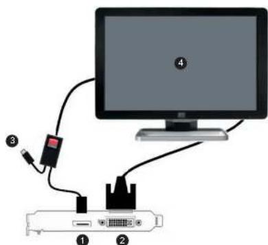
Image3-5
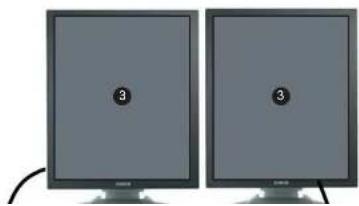
DVI6MPColorDiagnosticdisplay3MPColordisplay
1 DisplayPortconnectionwithdual-linkdongle
② DVI-Iconction
USBpowertocomputer
4 DVI6MPColorDiagnosticdisplayor3MPColordisplay
natural_image
Two gray rectangular blocks labeled 3 and 4, with no text or symbols beyond the numbers.3. Dongles
MXRT-4500, MXRT-5400, & MXRT-5500
DVINavigationdisplayandallGrayscaleor2MPColorDiagnosticdisplays
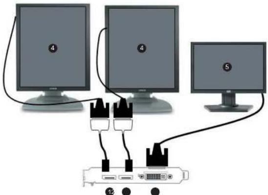
Image3-7
DVINavigationdisplayandallGrayscaleor2MPColorDiagnosticdisplays
1 DisplayPortwithsingle-linkdongle
② DisplayPortwithsingle-linkdongle
③ DVI-I
4 GrayscaleDiagnosticdisplayor2MPColorDiagnosticdisplay
5 ColorNavigationdisplay

3. Dongles
1 DisplayPort#1
2 DisplayPortconnectionwithsingle-linkdongle
③ DVI-I
4 ColorNavigationdisplay
5 GrayscaleDiagnosticdisplayor2MPColorDiagnosticdisplay
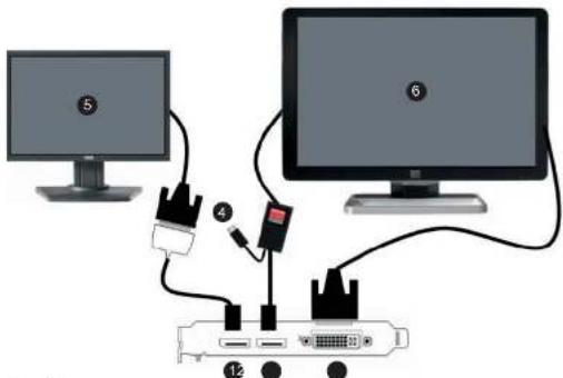
Image3-9 DVINavigationdisplayand6MPColorDiagnosticdisplayor3MPColordisplays
1 DisplayPortconnectionwithsingle-linkdongl
② DisplayPortconnectionwithdual-linkdongle
③ DVI-I
4 USBpowertocomputer
5 ColorNavigationdisplay
Image3-11
DVI Navigation display and all Grayscale or 2MP Color Diagnostic displays (see Tip)
1 DisplayPortconnectionwithsingle-linkdonale
3. Dongles
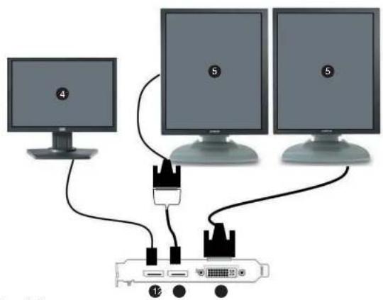
Image3-12
DisplayPortNavigationdisplayandallGrayscaleor2MPC
olorDiagnosticdisplays(see Tip)
1 DisplayPort#1
② DisplayPortconnectionwithsingle-linkdongle
③ DVI-I
4 ColorNavigationdisplay
5 GrayscaleDiagnosticdisplayor2MPColorDiagnosticdisplay

Diagnosticdisplaysmusthavematchingresolutions.
3. Dongles
1 DisplayPortconnectionwithdual-linkdongle
2 DisplayPortconnectionwithdual-linkdongle
③ DVI-I
4 USBpowertocomputer
5 6MPColorDiagnosticdisplayor2x3MPColordisplays
6 ColorNavigationdisplay
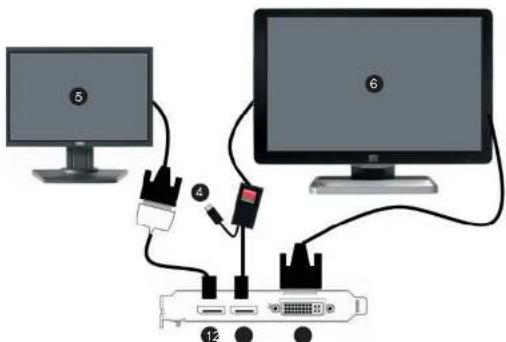
Image3-14
DisplayPort Navigation display and 6MP Color Diagnostic display or 3MP Color displays
1 DisplayPortconnectionwithsingle-linkdongle
② DisplayPortconnectionwithdual-linkdongle
③ DVI-I
4 USBpowertocomputer
• 2014年1月1日
3. Dongles
MXRT-7500
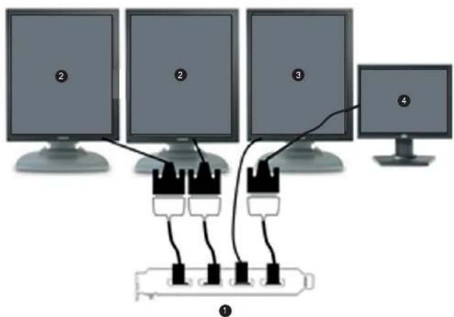
Image3-15
DVI Navigation display and Dual-head DVI Grayscale displays with an optional DisplayPort 3D display (see Tip).
1 DisplayPort#1through#4
2 GrayscaleDiagnosticdisplay(DVI)
3 3DDisplay(DP):thisisoptional
4 ColorNavigationdisplay
3. Dongles
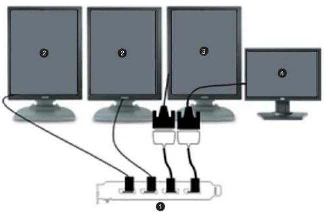
Image3-16
DVINavigationdisplayandDual-headDisplayPortGra yscaledisplayswithanoptionalDVI3Ddisplay
1 DisplayPort#1through#4
2 GrayscaleDiagnosticdisplay(DP)
3 3DDisplay(2MPColorDVI):thisisoptional
4 ColorNavigationdisplay
3. Dongles
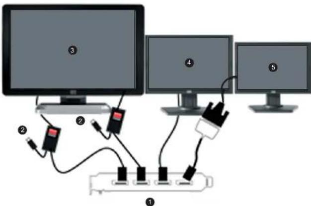
Image3-17
DisplayPortNavigationdisplayandDVI6MPColorDiag nostic display or 3MP Color displays with an optional third DVI display
1 DisplayPort#1through#4
2 USBpowertocomputer
3 6MPColorDiagnosticdisplayor2x3MPColorDiagnosticDVI(e.g.MDCC-6130)
4 ColorNavigationdisplay(DP)
5 ColorNavigationdisplay(DVI):thisisoptional
3. Dongles
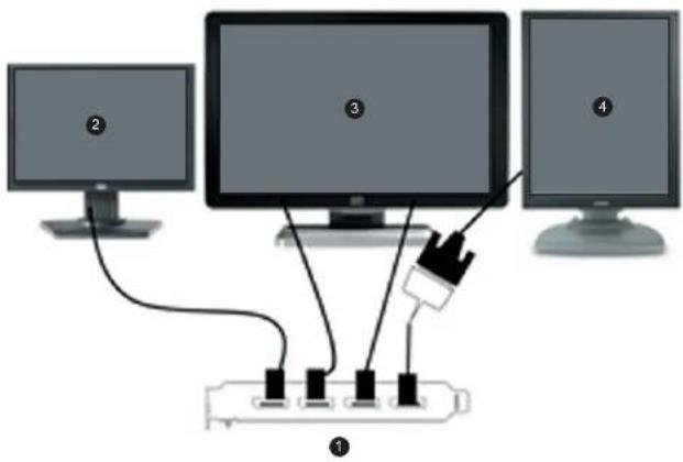
Image3-18
DisplayPortNavigationdisplayandDisplayPort6MPC colorDiagnosticdisplayor3MPColordisplayswithanoptionalDVI3Ddisplay
1 DisplayPort#1through#4
2 ColorNavigationDPdisplay(e.g.MDRC-2124)
3 6MPColorDiagnosticdisplayor2x3MPColorDiagnosticDPdisplay(e.g.MDCC-6230)
3DDisplay(2MPColorDVI):thisisoptional
- Dongles
4. DRIVERANDSOFTWARE INSTALLATION
4.1 Driver and software installation prerequisites
Prerequisites

Toinstallorremovethedrivers,software,ordocumentationyoumustbeloggedonas auserwithadministratorprivileges.
Youroperatingsystemmustbeinstalledandrunningbeforeyoucaninstallthedriver,softwareanddocumentationfortheBarcoDisplayController(s)foryourBarcoDisplaySystem.
Beforeyoubegin, makesurethatallofyourBarcoDisplaysareconnectedtotheappropriateDisplayController(s)inyoursystem.
4.2 InstallingtheBarcoMXRTdriversandsoftware
Introduction
Thischapterwillguideyouthroughtheinstallationofthedriver withyourBarcoDisplaySystemorBarcoDisplayController(s).
s,softwareanddocumentationassociated

The installation dialog will display in English if your operating system's language is not supported.
4. Driver and software installation
• After you have installed the BarcoDisplayController(s) for your BarcoDisplaySystem in your system for the first time.
- Afteryouhavereinstalledorupgradedyouroperatingsystem.
- WhenyouupgradetoanewerversionoftheMXRTdriverandsoftware. Youdonolneedtomanuallyuninstallanexistingdriverbeforeupdatingtothecurrentversion.The BarcoProductInstallationWizardwilldetectanypriorinstallationsandstarttheuninstallationprocess automaticallyifnecessary. If youhaveapreviousversionofConferenceCloneViewapplicationinstalledinthesystem,youneed to terminate the application prior to installing the new version. To do so, bring up Barco Clone Display(s) configuration window, select Stop Cloning, and close the window. When there is a non-Barco board in the system, we recommend that you first install the driver for the non-BarcoboardbeforeinstallingtheBarcodriver. Aftereachdriverinstallation,youshouldrebootthesystembeforeproceedingwiththeinstallationofanotherdriver.
Installationprocedure
The following will guide you through the installation procedure:
1.Startyoursystem. If you have fresh OS installation, or you have uninstalled an existing driver, the OS may automatically install an inbox driver from the Windows 7 driver store, either an AMD driver or an standard VGA driver, for the Barco Display Controller(s). If this occurs, the OS prompts you to restart your computer, click Yes to allow the automatic driver installation to complete and reboot the system.
2. LaunchtheBarcoProductInstallationWizard.TheinstallationWizardshouldstartautomaticallywhen youinserttheBarcoDisplaySystemInstallationDVDintoyourcomputer'sDVDdrive.Iftheinstallation does not start, in the "auto play" window, click Run setup.exe.
3. To accept the installation of default software components, click on Next. To custom select software components, click on Select Software Components and the following screen will appear, allowing selection of individual components.

- M X R T d r i v e r ( s )
-BarcoMedSelfExam:Barcodiagnostictool
-QAWebAgent:Barcocalibrationsoftware2
- SingleView: This application is required to configure Barco Fusion displays into SingleView mode orbackintoDualViewmode.InSingleView,thedisplayhasasinglelandscaperesolution,andin DualView,ithastwoside-by-sideportraitresolutions.
-ConferenceCloneView: An application that allows the user to clone 1 or 2 display to third display, such as a projector.
-DriverCleaner: An application that will remove all Barcosoftware components from your workstation.
- Display Installer: This file allows Windows to recognize Barco displays.
- Microsoft Hotfix for KB2496400: Resolved the issue that monitor configuration is lost after you restart acomputerthatisrunningWindows7. In a configuration that includes an MXRT-1150/2150 and other MXRT boards, two separate drivers will be installed. Themasterinstallation program will make top updates through the driver installation process (i.e. License Agreement, Verify Installation Options, etc.).
-
If a previous installation of an MXRT driver exists, the installation wizard will detect it and guide you through the uninstallation process if necessary.
-
Click Yes to accept the driver's License Agreement, and then Next to continue.
-
You will be prompted for Express or Custom Installation. By default, the Express Install option is selected. Custom Installation prompts two installation options:
- 30-bit Desktop: This option allows high dynamic range visualization of medical imaging on grayscale and color displays.
- SingleView: This option sets all Barco Fusion displays into SingleView mode.
-
During installation, the desktop may flash, and the Installation Wizard window may appear on different displays. This is expected behavior.
-
When the installation of all components has completed, the automatic reboot window will be displayed. Allow the system to reboot.
4.3 Afterinstallation
4. Driver and software installation
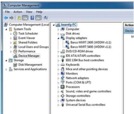
Image4-2
Verifyingdriverinstallation
Automaticdisplayconfiguration
Oncethedrivers, softwareanddocumentationhave been installed and your system has been rebooted, the computers should automatically detect your Barcodisplays and attach them to the desktop with the correct resolution. If the computer fail to detect your Barcodisplays or fail to attach them to the desktop correctly, please use the Windows Screen Resolution to set the correct resolution.
Reinstallingdrivers
4. Driver and software installation
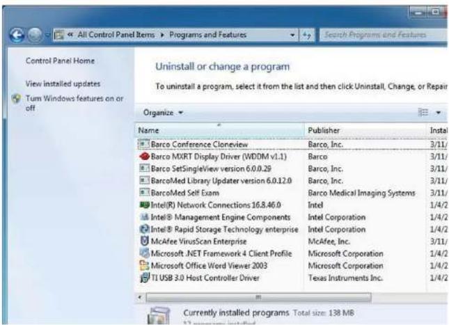
Image4-3
Windows/Add/RemovePrograms

When uninstalling the BarcoMXRT drivers, the following dialog box will appear. Select the driver listed you wish to install (driver version may be different than what is pictured below).
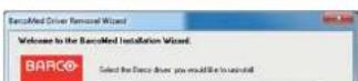
4.4Silentinstallationofdriversandsoftware
Pre-installation
OnceaBarcodriverhasbeenpre-loadedintothedriverstoreofaWindows7OS,subsequentinstallation ofthedriverwillbeintervention-free.
Topre-loadthedriversoftwareintothdriverstore, openacommandshellandnavigatetotheappropriate driverdirectoryandrunthePnPUtilapplicationwiththe-a"add"parameter.Forexample:
cdd:\Barco\drivers\VS32\MXRT
pnputil-a*.inf
The PnPUtil application will parse the inf files and add the MXRT drivers to the driver store.
If this is the first installation of a Barco driver, the trust prompt will ask whether you really want to install the driver. Check the box that says Always trust software from Barco and press OK. The PnPUtil application will confirm the driver is loaded into the driver store.
At this point you can change another directory and repeat this with other drivers. You will not see the trust prompt.
If you install using wildcards, you may see an error message that the Autorun.in format. This message is normally can be ignored.
When you have added allofthedriver that you will need to the driver store, you can create an image of the drive, and use it for staging additional systems. Allofthesystems with this driver store are a reset up for intervention-free silent installation.
Silentinstallation
For silent installation, first import the Barco published certificate into the certificate store. This certificate can be extracted from the driver catalog file located in the driver package. Pleasenotethatthecertificate changesovertime, sowerecommendextractingthecurrentoneeachtime.
Once imported, navigate to the Barco installation folder and execute the command setup.exe -silent. This can be done from the command shell, from the Run command, or from a command shortcut. The setupprogramwillautomaticallyinstallthedriversforanyBarcoMedorMXRTboardsthatarepresent, theBarcoMedSelfExamprogram,andQAWeb(ifpartoftheinstallationpackage).
Configuresilentinstalloptions
•IfsettoYes, QAWebwillauto-start.
- IfNo(default),scriptswillpreventQAWebfromlaunchinguntilafterthereboot.
NeverForceUninstall:
- IfsettoYes, theinstallerwillnotrequiretheusertouninstallpreviousBarcodrivers.
- IfNo(default),theinstallerpromptstheusertouninstallpre-existingdrivers.
- Driver and software installation
5. CONFIGURING WINDOWS
5.1ConfiguringSingleView
HowtoconfigureSingleView
- From the StartMenu, select All Programs.
- Under the Barco Programs folder, select the desired configuration:
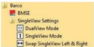
Image5-1
SingleViewStartMenuoptions

When your Fusion display is configured in SingleView mode, it is possible that the left andrightsidesoftheimagearenotinthecorrectorder.Inthiscase,clickontheSwap SingleViewLeft&Rightoption,anditwilladjusttheheadsonthedesktop.
5.2ConfiguringBarcoDisplayswiththeWindowsDisplayControlPanel
5. Configuring Windows
2.SelectaDisplay.
- In the Orientation dropdown list, these options are available:
-Landscape(norotation)
-Portrait(rotate90degrees)
-Landscape(flipped)
-Portrait(flipped)
- Select the desired setting, and click Apply.
6. CONFERENCECLONEVIEW
6.1 Whatis Conference Clone View?
Overview
Thisapplicationallowstheusertocloneoutputsfrom1or2displaystoathirddisplayorprojectorattached to the same Display Controller. The cloned image will be scaled to fit the resolution of the target display. The applicationsupportszoomingandpanningforeaseofviewing.
SupportedDisplayControllers
MXRT-1450&MXRT-1451, MXRT-2400, MXRT-2500, MXRT-4500, MXRT-5400, MXRT-5450, MXRT-5500, MXRT-5550, MXRT-7400&MXRT-7500.
6.2Configuration
Howtoconfigureyourdisplay(s)
- Start the Conference CloneView application either from the desktop icon or from Start -> Programs -> Barco, this will display the configuration window.
- SelecttheDisplayControllerthatisconnectedtothedisplay(s)youwouldliketoclonefromthedro down list. You can only clone displays connected to the same Display Controller. Click on Identify to seethedisplaysconnectedtothecurrentlyselectedDisplayController.
- Selectuptotwosourcedisplay(s) toclonefrom, and the target display where the cloned image will display, and click on the Create Clone button. By default, the source image(s) will be downscaled to fit the cloned display, while maintaining the original aspect ratio. Select Stretch to fill to stretch the cloned image to fit the cloned display's resolution, ignoring aspect ratio.
- Once all desired cloning has been configured, you may close the configuration window. The selected
6. Conference CloneView
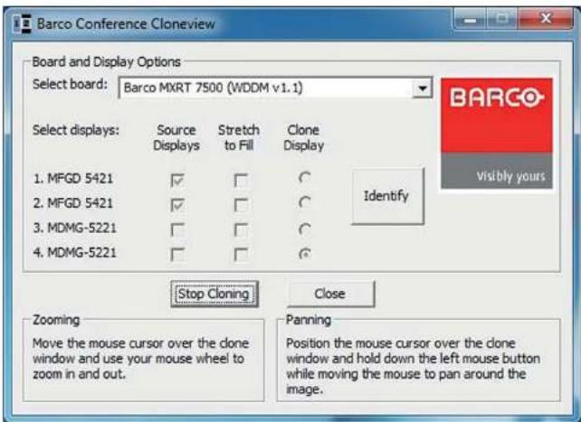
Image6-1
ConferenceCloneViewconfigurationwindow
6.3 Notificationicon
Systemtray
The Conference CloneView notification icon is available in the system tray once the Conference CloneView application has been launched. Right clicking on the icon offers the following menu options:
6.4 Tools available on the cloned display
When the mouse cursor is over to the cloned image, it will change to different shapes and the following control options are available:
Zoomingandpanning
Theusercanzoominontheclonedimagebyrollingthemousecursorwheel.
Whenzoomedin, the cloned imagemaybebiggerthantheclonedisplayandpartoftheimagemaybe offscreen. Clickandholdtheleftmousebuttonandmovethecursortopantotheportionoftheimage thatisoffscreen.
Clonedisplaymenuoptions
RightclickingontheclonedimagewillbringuptheConferenceCloneViewcontextmenu.
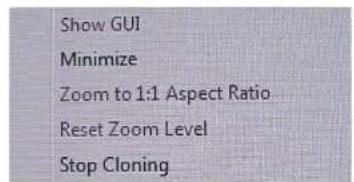
Image6-3
ConferenceCloneViewcontextmenu
Menuoptions:
- Show GUI: This option launches the configuration window. When the configuration window is already shown, this option is grayedout.
- Minimize: This minimizes the cloned image to show the desktop.
- Zoom to 1:1 Aspect Ratio: When "Stretch to fill" is selected in the configuration window, the aspect ratio of the cloned image may not match the source. Select this option to zoom directly to a 1:1 aspect ratio. When "Stretch to fill" is not selected, this option is grayed out.
-
Reset Zoom Level: Select this option to return to the minimize zoom level. When the image is already
-
Conference CloneView
7. IMPORTANT INFORMATION
7.1 Safetyinformation
General recommendations
Readthesafetyandoperatinginstructionsbeforeoperatingthedevice.
Retainsafety and operating instructions for further reference.
Adheretoallwamingsonthedeviceandintheoperatinginstructionsmanual.
Followallinstructionsforoperationanduse.
ElectricalShockorFireHazard
To prevent electric shock or fire hazard, do not remove cover.
No serviceable parts inside. Refer servicing to qualified personnel.
Donotexposethisapparatustorainormoisture.
Modificationstotheunit:
Donotmodifythisequipmentwithoutauthorizationofthemanufacturer.
Typeofprotection(Electrical)
Devicewithexternalpowersupply:Classlequipment.
Degreeofsafety(flammableanestheticmixture):
Equipment not suitable for use in the presence of a flammable anesthetic mixture with airorwithoxygen ornitrousoxide.
ThisDisplayControllerconformsto:
FAS B 115 AI B OF EU FRAA 115 B EU FRAN 115 AEREA 1 BULI OIA CIGRE 2024
TurkeyRoHScompliance

[RepublicofTurkey:InconformitywiththeWEEERegulation]
中国大陆 RoHS(EXAMPLE)
ChineseMainlandRoHS
According to the "China Administration on Control of Pollution Caused by Electronic Information Products" (Alsocalled RoHSofChinese Mainland), the table below lists these contents of toxic and/or hazardous substances that Barco's product may contain. The RoHSof Chinese Mainland is included in the MVC standard of the Ministry of Information Industry of China, in these section "Limit Requirements of toxic substances in Electronic Information Products".
| 零件项目(名称)Componentname | 有毒有害物质或元素Hazardoussubstancesandelements | |||||
| 铅Pb | 汞Hg | 镉Cd | 六价铬Cr6+ | 多溴联苯PBB | 多溴二苯醚PBDE | |
| 印制电路配件PrintedCircuitAssemblies | X | O | O | O | O | O |
| O:表示该有毒有害物质在该部件所有均质材料中的含量均在 SJ/T 11363-2006 标准规定的限量要求以下。O:IndicatesthatthistoxicorhazardoussubstancecontainedinallofthehomogeneousmaterialsforthispartisbelowthelimitrequirementinSJ/T11363-2006。X:表示该有毒有害物质至少在该部件的某一均质材料中的含量超出 SJ/T 11363-2006 标准规定的限量要求。X:Indicatesthatthistoxicorhazardoussubstancecontainedinatleastoneofthehomogeneous | ||||||
7.3 Regulatory compliance information
FCCclassB
This device complies with Part 15 of the FCC Rules. Operation is subject to the following two conditions: (1) this device may not cause harmful interference, and (2) this device must accept any interference received, including interference that may cause undesired operation.
This device has been tested and found to comply with the limits for a Class B digital device, pursuant to Part 15 of the FCC Rules. These limits are designed to provide reasonable protection against harmful interference in a residential installation. This device generates, uses and can radiate radio frequency energy and, if not installed and used in accordance with the instructions, may cause harmful interference toradiocommunication. However, there is no guarantee that interference will not occur in a particular installation. If this device does cause harmful interference or radioort television reception, which can be determined by turning the device off and, the user is encouraged to try to correct the interference by one or more of the following measures:
• Reorientorrelocatethereceivingantenna.
- Increase these separation between the device and receiver.
- Connectthe device into an outlet on a circuit different from that to which there is connected.
- Consultthedealeroranexperiencedradio/TVtechnicianforhelp.
Changes or modifications not expressly approved by the party responsible for compliance could void the user's authority to operate the equipment.
7.4 Explanationofsymbols
Symbolsonthedevice
On the device or power supply, you may find the following symbols (nonrestrictive list):

IndicatescompliancewiththeDirective93/42/EECasClassldevice
-
-
-
-
-
-
-
-
-
-
-
-
-
-
-
-
-
-
-
-
-
-
-
-
-
-
-
-
-
-
-
-
-
-
-
-
-
-
-
-
-
-
-
-
-
-
-
-
-
-
-
-
-
-
-
-
-
-
-
-
-
-
-
-
-
-
-
-
-
-
-
-
-
-
-
-
-
-
-
-
-
-
-
-
-
-
-
-
-
-
-
-
-
-
-
-
-
- 99.
-
-
-
-
-
-
-
-
-
-
-
-
-
-
-
-
-
-
-
-
-
-
-
-
-
-
-
-
-
-
-
-
-
-
-
-
-
-
-
-
-
-
-
-
-
-
-
-
-
-
-
-
-
-
-
-
-
-
-
-
-
-
-
-
-
-
-
-
-
-
-
-
-
-
-
-
-
-
-
-
-
-
-
-
-
-
-
-
-
-
-
-
-
-
-
-
7. Important information


Indicate the device is approved according to the VCCI regulations
IndicatesthedeviceisapprovedaccordingtotheKCregulations
Indicate the device is approved according to the BSMI regulations
Indicate the USB connectors on the device
Indicates the Display Port connectors on the device
Indicatesthemanufacturingdate
Indicatesthetemperaturelimitations ^3 forthedevicetosafelyoperatewithinspecs
Indicatesthedeviceserialno.
Warning:dangerousvoltage
Caution
7.5 Legaldisclaimer
Disclaimernotice
Although every attempt has been made to achieve technical accuracy in this document, we assume responsibility for error that may be found. Ourologist provide you with the most accurate and usable documentation possible; if you discover errors, please let us know.
BarcosoftwareproductsarethepropertyofBarco. TheyaredistributedundercopyrightbyBarcoN.V. or Barco, Inc., for use only under the specific terms of a software license agreement between Barco N.V. or Barcolnc.andthelicensee. Nootheruse,duplication,ordisclosureofaBarcosoftwareproduct,ina ny form,isauthorized.
The specifications of Barco products are subject to change without notice.
Trademarks
Alltrademarksandregisteredtrademarksarepropertyoftheirrespectiveowners.
Copyrightnotice
Thisdocumentiscopyrighted.Allrightsarereserved.Neitherthisdocument,noranypartofit,may bereproducedorcopiedinanyformorbyanymeans-graphical,electronic,ormechanicalincluding photocopying,tapingorinformationstorageandretrievalsystems-withoutwrittenpermissionofBarco.
©2014BarcoN.V.Allrightsreserved.
Patentinformation(EXAMPLE)
Thisproductiscoveredunderthefollowingintellectualpropertyrights:
USPatentRE43,707
USPatent7,038,186
USPatent7,166,829
USPatent6,950,098
EuropeanPatent1274066.
- Important information
| ConnectorsDMS-59 | |
| ConnectivityOneDMS-59-to-DVI | adaptorincluded |
| Supportedresolutions2560x1600 | DisplayPort,1920x1200DVI/Analog |
| DirectXsupport | Microsoft®DirectXv11.0 |
| OpenGLsupportOpenGL4.0 | |
| OpenCLsupportOpenCL1.0 | |
| Approvalsandcompliance | FCCPart15ClassB,CEEN55022LimitB,EN55024,UL-60950-1,BMSICNS,CISPR-22/24,IEC609050-1,VCCI,CSAC22.2,EUROHS directive (2002/95/EC), Certificate of Information & Communication Equipment(RepublicofKorea) |
| Operatingtemperature0°to60°C | (32°to140°F) |
MXRT-1451
| ProductacronymMXRT-1451 | |
| Buscompatibility | CouldbeinstalledwithinPCIExpressx1,x8,x16mechanicalslotsWorksinPCIExpressx1,x4,x8,x16electricalslots/operatesatx1 speed |
| Powerconsumption17Watt | |
| FormfactorLowprofile,half-length,2.3"x6.6" | |
| Operating system | Windows XP - 32/64-bit, Windows 7 - 32/64-bit, Windows 8.1 - 32/64-bit |
| Platforms | Intel®andAMDarchitectures |
| Graphicsaccelerator | ATI FirePro |
| Graphicsmemory | 1GBDDR3 |
| Memoryinterface | 64-bit |
| Memorybandwidth | 9.6GB/s |
| Pixeldepth | 32-bitcolor |
| Electricalstandard | Single-link DVI complying to v1.0 specification |
| ConnectorsDMS-59 | |
ConnectivityOneDMS 50 to DV/Indicators included
- Important information
| Graphicsmemory | 512MBDDR3 |
| Memoryinterface | 64-bit |
| Memorybandwidth | 14.4GB/s |
| Pixeldepth | 32-bitpixels(supports8-bitand10-bitpercolorchannel) |
| ElectricalstandardDual-linkDVI | complyingtov1.0,DisplayPortcomplyingtov1.1a |
| Connectors | 1-DVI-I,1-DisplayPort |
| ConnectivityOneDisplayPortto | Single-LinkDVI-Idongleincluded |
| Supportedresolutions | Upto6MPcolorand10MPgrayscale |
| DirectXsupport | Microsoft®DirectXv11.0,VertexShader5.0,PixelShader5.0 |
| OpenGLsupportOpenGL4.0 | |
| OpenCLsupportOpenCL1.0 | |
| Approvalsandcompliance | FCCPart15ClassB,CEEN55022LimitB,EN55024,UL-60950-1,BMSICNS,CISPR-22/24,IEC609050-1,VCCI,CSAC22.2,EURoHS directive (2002/95/EC), Certificate of Information & Communication Equipment(RepublicofKorea) |
| Operatingtemperature0°to60°C | (32°to140°F) |
MXRT-2500
| ProductacronymMXRT-2500 | |
| Buscompatibility | PCIeGen2x16 |
| Powerconsumption50Watt | |
| Form factor 168mm(L) x 68mm(H) single PCleslotwide | |
| OperatingsystemWindows7-32/64-bit, Windows8.1-32/64-bit | |
| Platforms | Intel®andAMDarchitectures |
| Graphicsaccelerator | ATI FirePro |
| Graphicsmemory | 1GBDDR3 |
| Memoryinterface | 128-bit |
| Memorybandwidth | 28.8GB/s |
7. Important information
| Form factor 163 mm (L) x 97 mm (H) single PCleslot wide | |
| OperatingsystemWindows7-32/64-bit, Windows8.1-32/64-bit | |
| PlatformsIntel®andAMDarchitectures | |
| Graphicsaccelerator | ATFirePro |
| Graphicsmemory1GBGDDR5 | |
| Memoryinterface | 128-bit |
| Memorybandwidth | 64GB/s |
| Pixeldepth | 32-bitpixels(supports8-bitand10-bitpercolorchannel) |
| ElectricalstandardDual-linkDV1complyingtov1.0, DisplayPortcomplyingtov1.2 | |
| Connectors | 1-DVI-I,2-DisplayPort |
| ConnectivityTwoDisplayPorttoSingle-LinkDVI-IdonglesincludedDisplayPorttoDual-LinkDVI-IdongleavailablefromBarco;PartNumberK9305104 | |
| Supportedresolutions | Upto6MPcolorand10MPgrayscale |
| DirectXsupport | Microsoft®DirectXv11.0,VertexShader5.0,PixelShader5.0 |
| OpenGLsupportOpenGL4.1 | |
| OpenCLsupport | OpenCL 1.1 |
| Approvalsandcompliance | FCCPart15ClassB,CEEN55022LimitB,EN55024,UL-60950-1,BMSICNS,CISPR-22/24,IEC609050-1,VCCI,CSAC22.2,EURoHS directive (2002/95/EC), Certificate of Information & Communication Equipment(RepublicofKorea) |
| Operatingtemperature | 0°to60°C(32°to140°F) |
MXRT-5400
| Productacronym | MXRT-5400 |
| Buscompatibility | PCIeGen2x16 |
| Powerconsumption | 72Watt |
| Formfactor | 230.53mm(L)x98.34mm(H)singlePCleslotwide |
| OperatingsystemWindowsXP-32 | 64-bit,Windows7-32/64-bit,Windows8.1-32/64-bit |
7. Important information
| Approvalsandcompliance | FCCPart15ClassB,CEEN55022LimitB,EN55024,UL-60950-1,BMSICNS,CISPR-22/24,IEC609050-1,VCCI,CSAC22.2,EUROHS directive (2002/95/EC), Certificate of Information & Communication Equipment(RepublicofKorea) |
| Operatingtemperature0°to60°C(32°to140°F) | |
MXRT-5450
| ProductacronymMXRT-5450 | ||
| Buscompatibility | PCIeGen2x16 | |
| Powerconsumption72Watt | ||
| Formfactor230.53mm(L)x98.34mm(H)singlePCleslotwide | ||
| OperatingsystemWindowsXP-32/64-bit,Windows7-32/64-bit,Windows8.1-32/64-bit | ||
| PlatformsIntel®andAMDarchitectures | ||
| Graphicsaccelerator | ATIFirePro | |
| Graphicsmemory1GBGDDR5 | ||
| Memoryinterface | 128-bit | |
| Memorybandwidth | 64GB/s | |
| Pixeldepth | 32-bitpixels(supports8-bitand10-bitpercolorchannel) | |
| ElectricalstandardDual-linkDVIcomplyinglov1.0 | ||
| Connectors | 2-DVI-I | |
| Connectivity | Dual-LinkDVICables | |
| Supportedresolutions | Upto6MPcolorand10MPgrayscale | |
| DirectXsupport | Microsoft®DirectXv11.0,VertexShader5.0,PixelShader5.0 | |
| OpenGLsupport | OpenGL4.0 | |
| OpenCLsupport | OpenCL1.0 | |
| Approvalsandcompliance | FCCPart15ClassB,CEEN55022LimitB,EN55024,UL-60950-1,EN55023,CIPTB, 60/61/50/200058.1/USQ1/SS1/SS2.0/EVT.1/USQ1/SS2.0/EVT.1/USQ1/SS2.0/EVT.1/USQ1/SS2.0/EVT.1/USQ1/SS2.0/EVT.1/USQ1/SS2.0/EVT.1/USQ1/SS2.0/EVT.1/USQ1/SS2.0/EVT.1/USQ1/SS2.0/EVT 1/USQ1/SS2.0/EVT.1/USQ1/SS2.0/EVT.1/USQ1/SS2.0/EVT.1/USQ1/SS2.0/EVT.1/USQ1/SS2.0/EVT.1/USQ1/SS2.0/EVT.1/USQ1/SS2.0/EVT.1/USQ1/SS2 1/USQ1/SS2.0/EVT.1/USQ1/SS2.0/EVT.1/USQ1/SS2.0/EVT.1/USQ1/SS2.0/EVT.1/USQ1/SS2.0/EVT.1/USQ1/SS2.0/EVT.1/USQ1/SS2.0/EVT.1/USQ1/SS3 1/USQ1/SS3.0/EVT.1/USQ1/SS3.0/EVT.1/USQ1/SS3.0/EVT.1/USQ1/SS3.0/EVT.1/USQ1/SS3.0/EVT.1/USQ1/SS3.0/EVT.1/USQ1/SS3.0/EVT.1/USQ1/SS3.0/EVT.1/USQ1/SS3 1/USQ1/SS3.0/EVT.1/USQ1/SS3.0/EVT.1/USQ1/SS3.0/EVT.1/USQ1/SS3.0/EVT.1/USQ1/SS3.0/EVT.1/USQ1/SS3.0/EVT.1/USQ1/SS4 1/USQ1/SS4.0/EVT.1/USQ1/SS4.0/EVT.1/USQ1/SS4.0/EVT.1/USQ1/SS4.0/EVT.1/USQ1/SS4.0/EVT.1/USQ1/SS4.0/EVT.1/USQ1/SS4.0/EVT.1/USQ1/SS4.0/EVT.1/USQ1/SS4 1/USQ1/SS4.0/EVT.1/USQ1/SS4.0/EVT.1/USQ1/SS4.0/EVT.1/USQ1/SS4.0/EVT.1/USQ1/SS4.0/EVT.1/USQ1/SS4.0/EVT.1/USQ1/SS5 1/USQ1/SS5.0/EVT.1/USQ1/SS5.0/EVT.1/USQ1/SS5.0/EVT.1/USQ1/SS5.0/EVT.1/USQ1/SS5.0/EVT.1/USQ1/SS5.0/EVT.1/USQ1/SS5.0/EVT.1/USQ1/SS5.0/EVT.1/USQ1/SS5 1/USQ1/SS5.0/EVT.1/USQ1/SS5.0/EVT.1/USQ1/SS5.0/EVT.1/USQ1/SS5.0/EVT.1/USQ1/SS5.0/EVT.1/USQ1/SS5.0/EVT.1/USQ1/SS6 1/USQ1/SS6.0/EVT.1/USQ1/SS6.0/EVT.1/USQ1/SS6.0/EVT.1/USQ1/SS6.0/EVT.1/USQ1/SS6.0/EVT.1/USQ1/SS6.0/EVT.1/USQ1/SS6.0/EVT.1/USQ1/SS6.0/EVT.1/USQ1/SS6 1/USQ1/SS6.0/EVT.1/USQ1/SS6.0/EVT.1/USQ1/SS6.0/EVT.1/USQ1/SS6.0/EVT.1/USQ1/SS6.0/EVT.1/USQ1/SS6.0/EVT.1/USQ1/SS7 1/USQ1/SS7.0/EVT.1/USQ1/SS7.0/EVT.1/USQ1/SS7.0/EVT.1/USQ1/SS7.0/EVT.1/USQ1/SS7.0/EVT.1/USQ1/SS7.0/EVT.1/USQ1/SS7.0/EVT.1/USQ1/SS7.0/EVT.1/USQ1/SS7 1/USQ1/SS7.0/EVT.1/USQ1/SS7.0/EVT.1/USQ1/SS7.0/EVT.1/USQ1/SS7.0/EVT.1/USQ1/SS7.0/EVT.1/USQ1/SS7.0/EVT.1/USQ1/SS8 1/USQ1/SS8.0/EVT.1/USQ1/SS8.0/EVT.1/USQ1/SS8.0/EVT.1/USQ1/SS8.0/EVT.1/USQ1/SS8.0/EVT.1/USQ1/SS8.0/EVT.1/USQ1/SS8.0/EVT.1/USQ1/SS8.0/EVT.1/USQ1/SS8 1/USQ1/SS8.0/EVT.1/USQ1/SS8.0/EVT.1/USQ1/SS8.0/EVT.1/USQ1/SS8.0/EVT.1/USQ1/SS8 1/USQ1/SS8.0/EVT.1/USQ1/SS8.0/EVT.1/USQ1/SS8.0/EVT 1/USQ1/SS8.0/EVT.1/USQ1/SS8.0/EVT.1/USQ1/SS8.0/EVT.1/USQ1/SS8 1/USQ1/SS8.0/EVT.1/USQ1/SS8.0/EVT.1/USQ1/SS8.0/EVT.1/USQ1/SS8 1/USQ1/SS8.0/EVT.1/USQ1/SS8.0/EVT.1/USQ1/SS8 1/USQ1/SS8.0/EVT.1/USQ1/SS8.0/EVT.1/USQ1/SS8 1/USQ1/SS8.0/EVT.1/USQ1/SS8 1/USQ1/SS8.0/EVT.1/USQ1/SS8 1/USQ1/SS8.0/EVT.1/USQ1/SS8 1/USQ1/SS8.0/EVT.1/USQ1/SS8 1/USQ1/SS8.0/EVIT 1/USQ1/SS8 1/USQ1/SS8 1/USQ1/SS8 1/USQ1/SS8 1/USQ1/SS8 1/USQ1/SS8 1/USQ1/SS8 1/USQ1/SS8 1/USQ1/SS8 1/USQ1/SS8 1/USQ1/SS8 1/USQ1/SS8 | ATIFirePro |
- Important information
| ElectricalstandardDual-linkDVIcomplyingtov1.0,DisplayPortcomplyingtov1.2 | |
| Connectors | 1-DVI-I,2-DisplayPort |
| ConnectivityTwoDisplayPorttoS | ngle-LinkDVI-IdonglesincludedDisplayPorttoDual-LinkDVI-IdongleavailablefromBarco;PartNumberK9305104 |
| Supportedresolutions | Upto6MPcolorand10MPgrayscale |
| DirectXsupport | Microsoft®DirectXv11.1,VertexShader5.0,PixelShader5.0 |
| OpenGLsupportOpenGL4.2 | |
| OpenCLsupportOpenCL1.2 | |
| Approvalsandcompliance | FCCPart15ClassB,CEEN55022LimitB,EN55024,UL-60950-1,BMSICNS,CISPR-22/24,IEC609050-1,VCCI,CSAC22.2,EURoHSdirective(2002/95/EC),CertificateofInformation&CommunicationEquipment(RepublicofKorea) |
| Operatingtemperature0°to60°C(32°to140°F) | |
MXRT-5550
| ProductacronymMXRT-5550 | |
| Buscompatibility | PCIeGen3x16 |
| Powerconsumption75Watt | |
| Formfactor184.15mm(L)x111mm(H)singlePCleslotwide | |
| Operatingsystem | Windows7-32/64-bit,Windows8.1-32/64-bit |
| Platforms | Intel®andAMDarchitectures |
| Graphicsaccelerator | ATIFirePro |
| Graphicsmemory | 2GBGDDR5 |
| Memoryinterface | 256-bit |
| Memorybandwidth | 102.3GB/s |
| Pixeldepth | 32-bitpixels(supports8-bitand10-bitpercolorchannel) |
| ElectricalstandardDual-linkDVIcomplyingtov1.0 | |
- Important information
| Formfactor281.29mm(L)x98.53mm(H)singlePCleslotwide | |
| OperatingsystemWindowsXP-32/64-bit,Windows7-32/64-bit,Windows8.1-32/64-bit | |
| PlatformsIntel®andAMDarchitectures | |
| Graphicsaccelerator | ATFirePro |
| Graphicsmemory2GBGDDR5 | |
| Memoryinterface256-bit | |
| Memorybandwidth | 128GB/s |
| Pixeldepth | 32-bitpixels(supports8-bitand10-bitpercolorchannel) |
| ElectricalstandardDual-linkDVIcomplyingtov1.0,DisplayPortcomplyingtov1.1a | |
| Connectors | 1-DVI-I,2-DisplayPort |
| ConnectivityTwoDisplayPorttoSingle-LinkDVI-IdonglesincludedDisplayPorttoDual-LinkDVI-IdongleavailablefromBarco;PartNumberK9305104 | |
| Supported resolutions | Up to 6MP color and 10MP grayscale |
| DirectXsupport | Microsoft®DirectXv11.0,VertexShader5.0,PixelShader5.0 |
| OpenGLsupport | OpenGL4.0 |
| OpenCLsupport | OpenCL1.0 |
| Approvalsandcompliance | FCCPart15ClassB,CEEN55022LimitB,EN55024,UL-60950-1,BMSICNS,CISPR-22/24,IEC609050-1,VCCI,CSAC22.2,EUROHS directive(2002/95/EC),CertificateofInformation&Communication Equipment(RepublicofKorea) |
| Operatingtemperature | 0°to60°C(32°to140°F) |
MXRT-7500
| Productacronym | MXRT-7500 |
| Buscompatibility | PCIeGen3x16 |
| Powerconsumption | 140Watt |
| Powerconnector | One2x3powerconnector |
- Important information
| Approvalsandcompliance | FCCPart15ClassB,CEEN55022LimitB,EN55024,UL-60950-1,BMSICNS,CISPR-22/24,IEC609050-1,VCCI,CSAC22.2,EUROHS directive(2002/95/EC),CertificateofInformation&Communication Equipment(RepublicofKorea) |
| Operatingtemperature0°to60°C(32°to140°F) | |
- TABLEOFCONTENTS
- 1.WELCOME!
- About the product
- DisplayController
- What'sinthebox
- Contents
- 2.DISPLAYCONTROLLERINSTALLATION
- Which DisplayController?
- DisplayControllerrange
- InstallingaBarcoDisplayController
- Guidance
- Overview
- Types of Display Controllers for Barco Display Systems
- Display Controller installation
- WhichPCleslottouse
- Installation procedure
- Howtoinstall
- Connecting your Barco Displays
- Dongles
- 3.DONGLES
- Passive Single-Link Dongle
- PassiveSingle-Link
- Dual-LinkDongle
- Dual-Link
- 3.4Commoncases
- MXRT-4500, MXRT-5400, & MXRT-5500
- DRIVERANDSOFTWARE INSTALLATION
- Driver and software installation prerequisites
- InstallingtheBarcoMXRTdriversandsoftware
- Driver and software installation
- Installationprocedure
- Afterinstallation
- Automaticdisplayconfiguration
- Reinstallingdrivers
- 4.4Silentinstallationofdriversandsoftware
- Pre-installation
- Silentinstallation
- NeverForceUninstall:
- CONFIGURING WINDOWS
- 5.1ConfiguringSingleView
- HowtoconfigureSingleView
- 5.2ConfiguringBarcoDisplayswiththeWindowsDisplayControlPanel
- CONFERENCECLONEVIEW
- Whatis Conference Clone View?
- SupportedDisplayControllers
- 6.2Configuration
- Howtoconfigureyourdisplay(s)
- Conference CloneView
- Notificationicon
- Systemtray
- Tools available on the cloned display
- Zoomingandpanning
- Clonedisplaymenuoptions
- Menuoptions:
- IMPORTANT INFORMATION
- Safetyinformation
- General recommendations
- ElectricalShockorFireHazard
- Modificationstotheunit:
- Typeofprotection(Electrical)
- Degreeofsafety(flammableanestheticmixture):
- ThisDisplayControllerconformsto:
- TurkeyRoHScompliance
- 中国大陆 RoHS(EXAMPLE)
- Regulatory compliance information
- FCCclassB
- Explanationofsymbols
- Symbolsonthedevice
- Legaldisclaimer
- Disclaimernotice
- Trademarks
- Copyrightnotice
- Patentinformation(EXAMPLE)
Brand : Barco
Model : FirePro MXRT-5400
Category : Video card