
FirePro V5800 - Video card Barco - Free user manual and instructions
Find the device manual for free FirePro V5800 Barco in PDF.


| Product Type | Medical Display Controller (Graphics Card) |
| Model | Barco FirePro V5800 (equivalent to MXRT-5400) |
| Bus Interface | PCI Express Gen2 x16 |
| Graphics Accelerator | ATI FirePro (AMD) |
| Video Memory | 1 GB GDDR5 |
| Memory Interface | 128-bit |
| Memory Bandwidth | 64 GB/s |
| Pixel Depth | 32-bit (8 or 10-bit per color channel) |
| Supported Resolutions | Up to 6 MP color, 10 MP grayscale |
| Output Connectors | 1x DVI-I, 2x DisplayPort |
| DirectX Support | DirectX 11.0, Vertex Shader 5.0, Pixel Shader 5.0 |
| OpenGL Support | OpenGL 4.0 |
| Power Consumption | 72 Watt (max) |
| Form Factor | 230.53 x 98.34 mm, single PCIe slot |
| Operating Temperature | 0 to 60°C |
| Regulatory Compliance | FCC Class B, CE, UL, RoHS |
| Included Accessories | Single-link DisplayPort to DVI-I adapter (2 pcs) |
| Dongle Support | Single-link and Dual-link DP to DVI dongles |
| Operating System Support | Windows XP (32/64-bit), Windows 7 (32/64-bit) |
| ESD Protection | Grounded ESD strap required during installation |
| Warranty | Standard 12 months hardware, 3 months software |
Frequently Asked Questions - FirePro V5800 Barco
User questions about FirePro V5800 Barco
0 question about this device. Answer the ones you know or ask your own.
Ask a new question about this device
Download the instructions for your Video card in PDF format for free! Find your manual FirePro V5800 - Barco and take your electronic device back in hand. On this page are published all the documents necessary for the use of your device. FirePro V5800 by Barco.
USER MANUAL FirePro V5800 Barco
natural_image
Close-up of a FirePro 3D Graphics VR headset with red circuit board and NVIDIA logo (no text-heavy elements)(This page intentionally left blank.)
Welcome!
Thank you for choosing this BARCO DISPLAY CONTROLLER!
Barco's state-of-the-art display controllers deliver the performance, quality and stability required for today's advanced medical imaging applications. The powerful boards ensure ultra-fast and smooth image loading, roaming and manipulation of images in every resolution.
Use the instructions in this guide to install your BARCO DISPLAY CONTROLLER and discover the power yourself!
Following symbols may be used throughout this guide:
 | Warning: Risk of injury to human beings |  | Caution: Risk of damage to the product |
 | Important notice or remark |  | Note |
 | Hint, tip Additional |  | information |
(This page intentionally left blank.)
Table of contents
What's in the box 7
Display controller installation 9
Which display controller? 9
Installing a Barco display controller....9
Installation Procedure....11
Dongles....15
Single-Link dongle 15
Dual-Link dongle....16
Common cases....18
Driver and software installation 25
Driver and software installation prerequisites....25
Installing the BARCO MXRT drivers and software....26
Configuring Windows 31
Setting the resolution of your BARCO DISPLAY CONTROLLER ....31
Configuring Windows Theme 31
Configuring Clone (duplicate) Mode....32
Configuring Software Rotation 32
Important information 33
Environmental information....33
Regulatory compliance information....36
Explanation of symbols....37
Legal disclaimer....38
Technical specifications....39
Warranty statement....47
(This page intentionally left blank.)
What's in the box
Your BARCO DISPLAY CONTROLLER comes with:
•This B ARCO DISPLAY CONTROLLER guide
•System CD
- 2 single-link dongles are included with the MXRT 5400 & MXRT 7400.
- 1 single-link dongle is included with the MXRT 2400.
Keep your original packaging. It is designed for this BARCO DISPLAY CONTROLLER and is the ideal protection during transport.
(This page intentionally left blank.)
Display controller installation
Which display controller?
Your Barco medical display is compatible with a large range of Barco and non-Barco display controller boards. Depending on the order details, the display can be delivered with or without a display controller.
The brochure "Barco medical display systems" on the website www.barco.com/medical (Downloads section) contains a comprehensive overview of the compatibility matrix of Barco displays and Barco display controllers.
If you are using Barco display controllers, please follow the installation instructions in this section. If you are using a non-Barco display controller, please consult its corresponding documentation.
Installing a Barco display controller
This chapter will guide you through the physical installation of a Barco display controller for your display system.

Wear a grounded, protective ESD strap when handling or during installation of the display controller. Electrostatic charges can damage the display controller.
Overview
Prior to installing the Barco display controller(s) for your Barco Display System in your PC please take a few minutes to familiarize yourself with the display controller(s) and the PCIe slots in your computer.
TYPES OF DISPLAY CONTROLLERS FOR BARCO DISPLAY SYSTEMS
The following models of Barco display controllers are available for your display system. Please check which of the following models is delivered with your system, and follow the corresponding installation instructions:
Board Model Compatible PCIe Slot
Barco MXRT 1150 x1*, x8, x16
Barco MXRT 2150 x16
Barco MXRT 2400 x16
Barco MXRT 5200 x16
Barco MXRT 5400 x16
Barco MXRT 5450 x16
Barco MXRT 7300 x16
Barco MXRT 7400 x16
* Recommended PCIe slot
You can use x16 & x8 slots for x1 boards.
Which PCIe slot to use
The table on the preceding page lists the different display controller model(s) available for your BARCO Display System and the recommended PCIe slot to use for optimum performance. Below shows the different types of PCIe slots that can be used.
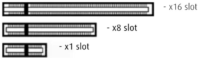
Examples of PCIe slots
Installation Procedure
The following instructions will take you step by step through the installation of the Barco display controller(s) for your Barco Display System.

Wear a grounded, protective ESD strap when handling or during installation of the display controller. Electrostatic charges can damage the display controller.
1If you are not going to use your old graphics card, uninstall the drivers and software for it if you have not already done so.
2Turn off the computer, display(s), and other peripheral devices.
3Unplug the computer's power cord and disconnect all cables from the back of your computer.

Wait approximately 20 seconds after unplugging the power cord before disconnecting a peripheral or removing a component from the motherboard to avoid possible damage to the motherboard.
4Remove the computer cover.
If necessary, consult your computer's manual for help in removing the cover.
5If necessary, unscrew or unfasten and remove any existing graphics card(s) from your computer.

If you are using a motherboard containing an on-board graphics solution and do not intend to use it as part of a multiple-display setup, disable it either in the computer's System Set-up utility (BIOS) or the Windows device manager.
6 Locate the appropriate slot and, if necessary, remove the metal back-plate cover(s).
7Align the Barco display controller(s) for your Barco Display System with the slot(s) and press it(them) in firmly until the card(s) is(are) fully seated.

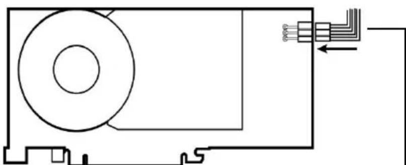
The next step applies only to the MXRT 7300 & MXRT 7400.
8Connect the power cable to the 6-pin power connection on the graphics card. Make sure the cables are not interfering with anything inside the computer (for example, a cooling fan).
natural_image
Pure electrical circuit lines without any symbols6-pin graphics controller power cable
Power connection for the MXRT 7300 & MXRT 7400 controllers
9Screw in or fasten the display controller securely. Replace and secure the computer cover.
CONNECTING YOUR BARCO DISPLAYS
For a detailed description of the display installation and signal connection, please refer to the Display User Guide.
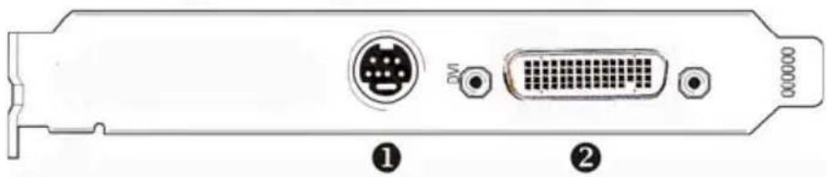
MXRT 1150 & MXRT 2150
IO-Panel for the Barco MXRT 1150 and Barco MXRT 2150
| 1 | S-Video ConnectionThis option is not supported by Barco. |
| 2 | DMS-59 connector provides DVI-I / Head 1 & Head 2 output connections through included Y adaptor cable. |
natural_image
Diagram of a computer RAM card rear panel showing internal components including an I/O port, DNA port, and connector (no text or labels)MXRT 2400
IO-Panel for the Barco MXRT 2400
| 1 | DisplayPort Connection |
| 2 | DVI-I Connection |
natural_image
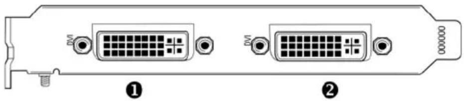
Diagram of a computer RAM card rear panel showing two D-subsets and one connector (no text or labels)MXRT 5200 & MXRT 5450
10-Panel for the Barco MXRT 5200 & MXRT 5450
1 Head 1-DVI-I Connection
2 Head 2- DVI-I Connection
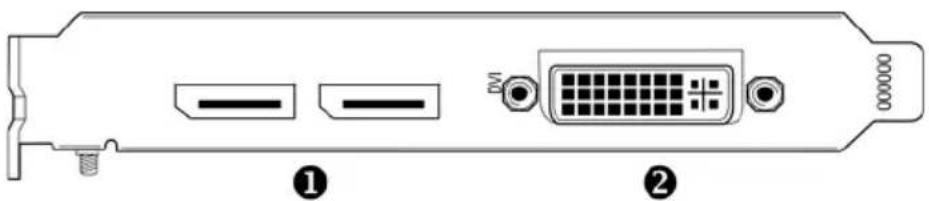
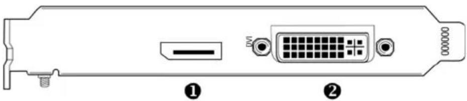
MXRT 5400, MXRT 7300, & MXRT 7400
IO-Panel for the Barco MXRT 5400, MXRT 7300, & MXRT 7400
1 DisplayPort Connections
2 DVI-I Connection
Disconnecting the DisplayPort cable may lock the display. Rebooting system may be required if lock occurs.
Driving three displays is not supported with MXRT 7300, for which only two of the three connectors can be used at a time.
Dongles
Barco dongles are specially designed to allow BARCO DISPLAY CONTROLLERS with a DisplayPort output to be connected with a display with DVI input.
Single-Link dongle
The Single-Link dongle allows to connect a display's DVI input with the DisplayPort output of your BARCO DISPLAY CONTROLLER. However, the Single-Link dongle is limited to convert resolutions to 2MP for color displays and 5MP for grayscale displays. If your display features higher resolutions, the Dual-Link dongle should be used instead.

All BARCO DISPLAY CONTROLLERS compatible with the DisplayPort interface come with a Single-Link dongle by default.
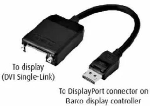
SingleLink Dongle (supplied with system)
Dual-Link dongle
The Dual-Link dongle also converts DisplayPort input signals to DVI output signals. However, unlike the Single-Link dongle, the Dual-Link dongle offers higher resolutions for both color and grayscale displays.

A Dual-Link DVI cable must be used to connect your display's DVI connector with the DVI connector on the Dual-Link dongle.

The Dual-Link dongle should be ordered separately.
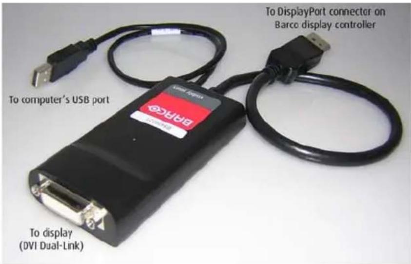
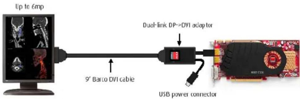
DisplayPort to Dual-Link DVI Dongle - enables full refresh rate support on color display resolutions over 1920x1200, and grayscale display resolutions over 2048x2560. Must be ordered separately.
The Dual-Link Dongle is only needed with graphics cards that have an active DisplayPort output, such as the MXRT-7300. Use the following steps to install the dongle:
1Connect the DisplayPort end of the connector to the graphics card.
2Plug in a Dual-Link DVI cable from the display into the DVI adapter of the dongle.
3Connect the built-in USB power cable on the dongle to a workstation USB port.
4If you are using QAWebAgent version 1.10.2 or older, then a separate software component is required for supporting DDC communication through the dual link dongle. Run setup.exe from Barco_DLDP2DVI_Install package after driver installation to install the SW.
flowchart
graph LR
    A["Up to 6mp"] --> B["9° Barco DVI cable"]
    B --> C["Dual-link DP->DVI adaptor"]
    C --> D["USB power connector"]
DPDVI DL Dongle Installation
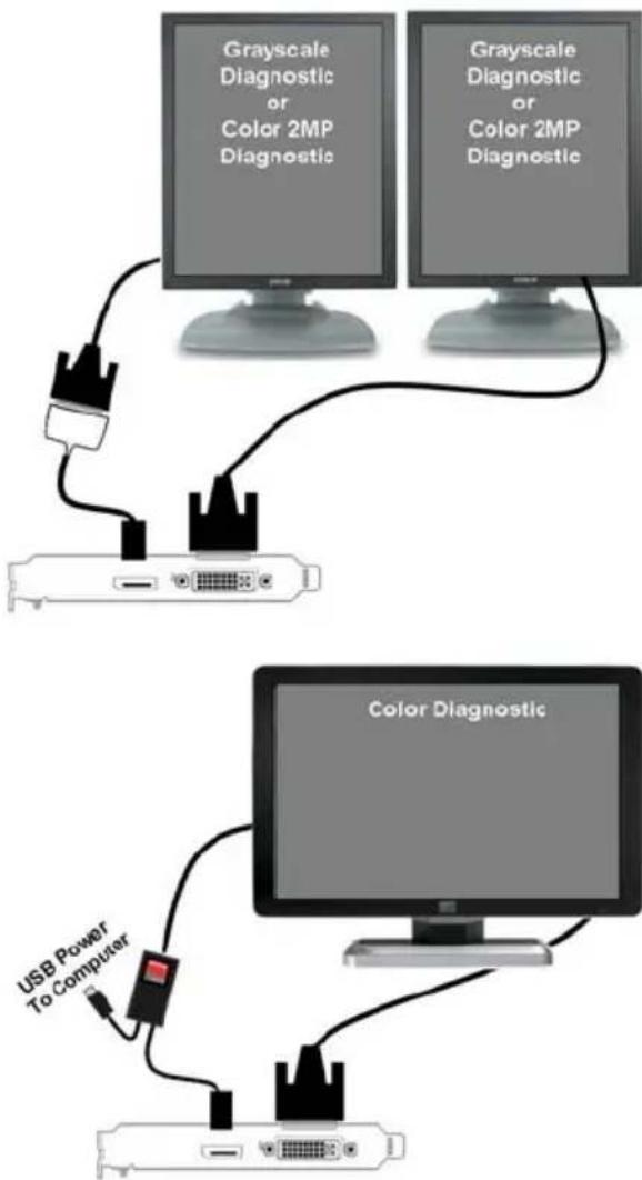
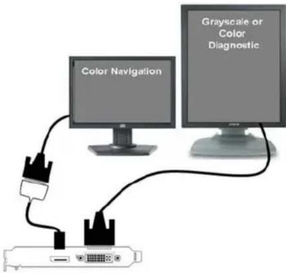
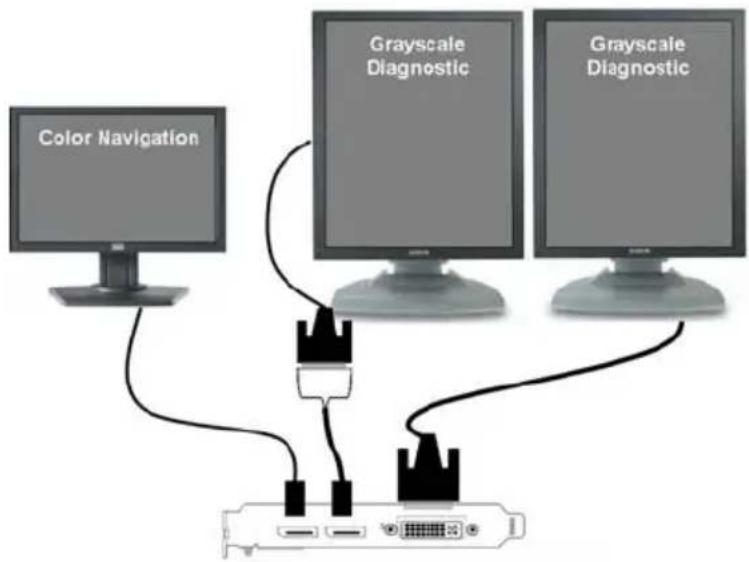
Common cases
MXRT 2400
flowchart
graph TD
    A["Computer monitor"] --> B["Grayscale Diagnostic or Color 2MP Diagnostic"]
    A --> C["Grayscale Diagnostic or Color 2MP Diagnostic"]
    D["Computer monitor"] --> E["Color Diagnostic"]
    F["USB Power To Computer"] --> G["USB Power To Computer"]
MXRT 2400
flowchart
graph TD
    A["USB Cable"] --> B["Color Navigation"]
    B --> C["Grayscale or Color Diagnostic"]
MXRT 5400
flowchart
graph TD
    A["Color Navigation"] --> B["Port"]
    C["Grayscale Diagnostic"] --> B
    D["Grayscale Diagnostic"] --> B
    B --> E["Port"]
    style A fill:#999
    style C fill:#ccc
    style D fill:#ccc
    style B fill:#fff
    style E fill:#fff
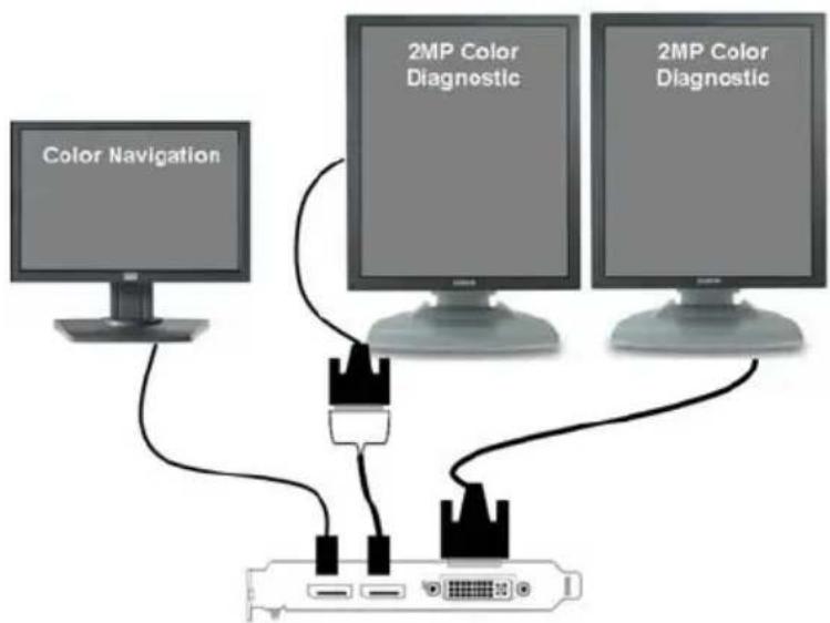
flowchart
graph TD
    A["Color Navigation"] --> B["2MP Color Diagnostic"]
    A --> C["2MP Color Diagnostic"]
    B --> D["Router"]
    C --> D
    D --> E["Router"]
MXRT 5400
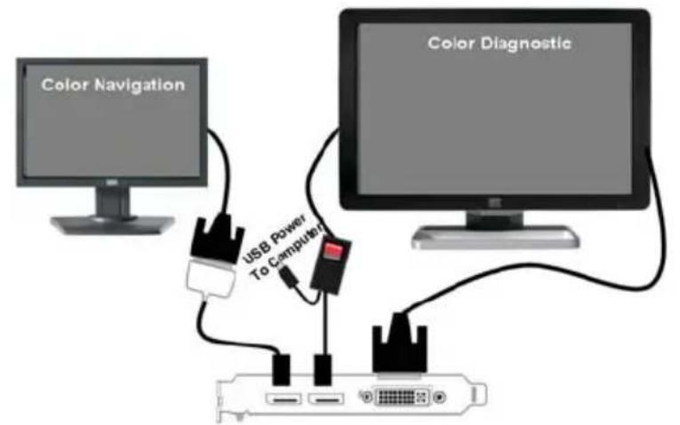
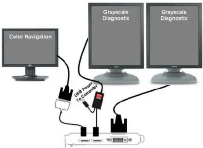
flowchart
graph TD
    A["Color Navigation"] --> B["USB Power To Computer"]
    C["Grayscale Diagnostic"] --> B
    D["Grayscale Diagnostic"] --> B
    B --> E["Computer"]
    style A fill:#99ccff,stroke:#333
    style C fill:#99ccff,stroke:#333
    style D fill:#99ccff,stroke:#333
MXRT 7400
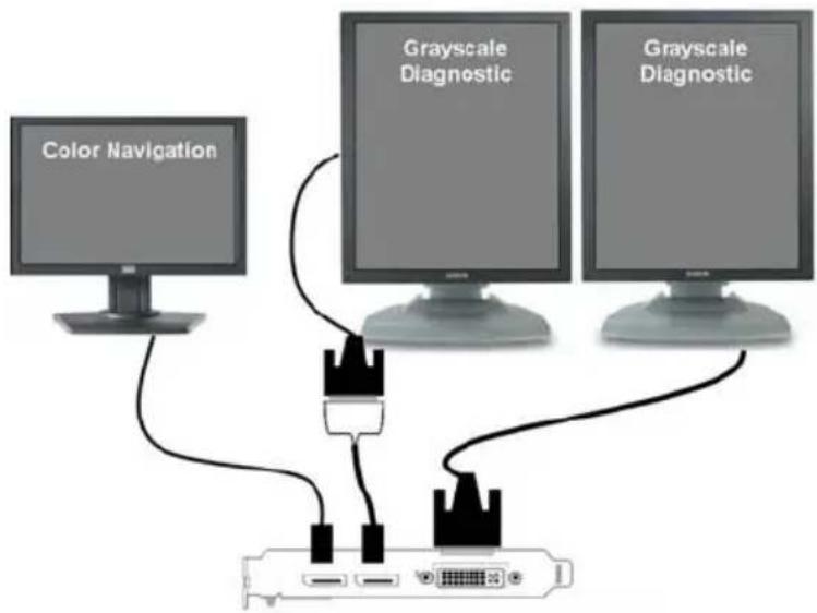
flowchart
graph TD
    A["Color Navigation"] --> B["Port"]
    C["Grayscale Diagnostic"] --> B
    D["Grayscale Diagnostic"] --> B
    B --> E["Port"]
    style A fill:#999
    style C fill:#ccc
    style D fill:#ccc
    style B fill:#fff
    style E fill:#fff
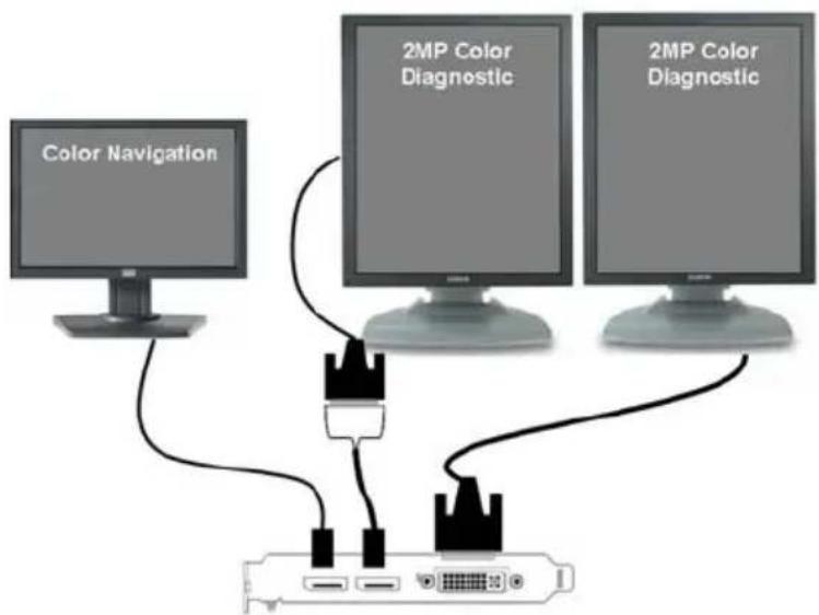
flowchart
graph TD
    A["Color Navigation"] --> B["2MP Color Diagnostic"]
    A --> C["2MP Color Diagnostic"]
    B --> D["Router"]
    C --> D
    D --> E["Router"]
MXRT 7400
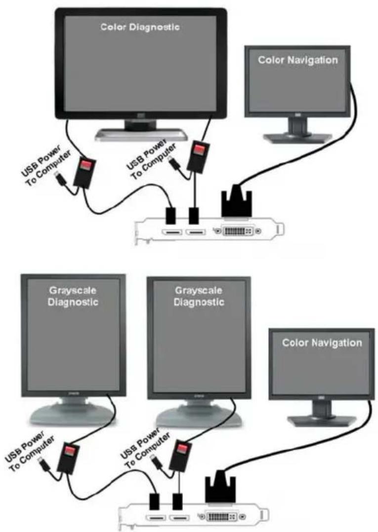
flowchart
graph TD
    subgraph_Top_Dialog["Top Diagram"]
        A1["Color Diagnostic"] --> B1["USB Power To Computer"]
        A2["Color Navigation"] --> B2["USB Power To Computer"]
        B1 --> C1["Computer"]
        B2 --> C2["Computer"]
        C1 --> D1["Gray Scale Diagnostic"]
        C2 --> D2["Gray Scale Diagnostic"]
        D1 --> E1["Computer"]
        D2 --> E2["Computer"]
    end
    subgraph_Bottom_Dialog["Bottom Diagram"]
        F1["Color Navigation"] --> G1["USB Power To Computer"]
        F2["Grayscale Diagnostic"] --> G2["USB Power To Computer"]
        F3["Grayscale Diagnostic"] --> G3["USB Power To Computer"]
        G1 --> H1["Computer"]
        G2 --> H2["Computer"]
        G3 --> H3["Computer"]
    end
(This page intentionally left blank.)
Driver and software installation
This chapter will guide you through the installation of the drivers, software and documentation associated with your BARCO Display System or BARCO DISPLAY CONTROLLER(s).
Driver and software installation prerequisites

To install or remove the drivers, software, or documentation you must be logged on as a user with administrator privileges.
Your operating system must be installed and running before you can install the driver, software and documentation for the Barco display controller(s) for your Barco Display System.
Before you begin make sure that all of your BARCO DISPLAY CONTROLLER(s) is connected to the appropriate display controller(s) in your system.

This installation procedure is based on operating Windows in "Classic" theme. If "Aero" or "Basic" theme is selected in Windows, sections of this procedure may be different than what is listed.
Installing the BARCO MXRT drivers and software

The installation dialog will display in English if your operating system's language is not supported.
This process applies to the following versions of Windows:
•Windows 7 32 & 64 Bit
You will need to install the BARCO DISPLAY CONTROLLER system drivers and software in the following cases:
• After you have installed the Barco display controller(s) for your Barco Display System in your system for the first time.
•After you have reinstalled or upgraded your operating system.
- When you upgrade to a newer version of the MXRT driver.
You do not need to manually uninstall an existing driver before updating to the current version. The Barco Product Installation Wizard will detect any prior installations and start the uninstallation process automatically if necessary.
When there is a non-Barco board in the system, we recommend that you first install the driver for the non-Barco board, prior to installation of the Barco driver. After each driver installation, you should reboot the system, before proceeding with installation of another driver.
The following will guide you through the installation procedure:
1 Start your system. If you have a fresh OS installation, the OS will automatically install an ATI driver (Windows 7 inbox driver) for the Barco MXRT Graphics Card(s). When the OS prompts you to restart your computer, click yes, to allow the automatic driver installation to complete, and reboot the system.
2 Launch the Barco Product Installation Wizard. The installation Wizard should start automatically when you insert the Barco Display System Installation DVD into your computer's DVD drive. If
the installation does not start, in the "auto play" window, click Run setup.exe.
3 If a previous installation of MXRT driver is present, the installation wizard will detect it and guide you through the uninstallation process if necessary.
4By default, choose the Express Install option. The Master installer will install the following components:
•BMSE
•QAWebAgent
• Graphics Driver
5 Click "Yes" to accept driver's License Agreement, and then "Next" to continue.

In a mixed board configuration (MXRT1150/2150 and MXRT5200/7300), two separate drivers will be installed.. The master Install program will make two passes through the driver installation process (i.e. License Agreement, Verify Installation Options, etc.).
6 During installation, there may be a fair amount of display flashing, and the install wizard window may appear on different displays. This is an expected behavior.
7 When the installation of all components has completed, the automatic reboot window will be displayed. Allow the system to reboot.
To verify that the driver was installed, go to the Windows Control Panel, select System, select Device Manager, then select Display
Adapters. Verify that Barco MXRT graphics boards were properly identified, as shown below:
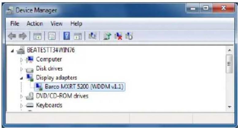
Automated display configuration
Once the drivers, software and documentation have been installed and your system has been rebooted, the computer should automatically detect your Barco displays and attach them to the desktop with the correct resolution. If the computer fails to detect your Barco displays or fails to attach them to the desktop correctly, please refer to the "Setting the resolution of your BARCO DISPLAY CONTROLLER" on page 31 in the Configuring Windows section of this manual.
Reinstalling drivers
You can install new drivers or reinstall existing drivers at any time by using the Barco Set-up wizard on your BARCO Display System Installation CD-ROM.
Uninstalling the drivers and software
To uninstall the Barco drivers, software or documentation for your Barco Display Systems, please use the Windows Add/Remove Program. This can be found in the Windows Control Panel under Programs & Features.

When uninstalling the Barco MXRT drivers, the following dialog box will appear, and select the driver listed if not already selected (driver version may be different than what is pictured below).
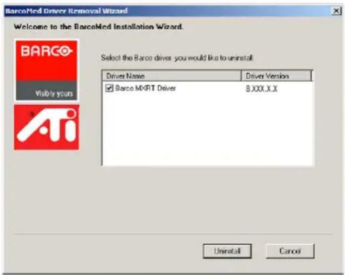
Barco MXRT Driver Removal Wizard
After uninstalling the driver, shutdown the machine and remove the card. If you leave the card in the system, Windows 7 will automatically attempt to reinstall the driver.
Silent Installation of Drivers and Software
Once A Barco graphics driver has been pre-loaded into the driver store of a Windows 7 OS, subsequent installation of the driver would be intervention-free.
To pre-load the driver software into the driver store, open a command shell and navigate to the appropriate driver directory and run the PnPUtil program with the -a "add" parameter. For example:
cd d:\Barco\drivers\VS32\MXRT
pnputil -a *.inf
The PnPUtil will parse the inf files and add the MXRT drivers to the driver store.
If this is the first installation of a Barco driver, the trust prompt will ask whether you really want to install the driver. Check the box that says "Always trust software from Barco" and press OK. The PnPUtil will confirm the driver is loaded into the driver store.
At this point you can change to another directory and repeat this with other drivers.
Since you have indicated that you always trust Barco software, you will not see the trust prompt.
If you install using wildcards, you may see an error message that the Autorun.inf was not an expected format. This is expected and is harmless.
When you have added all of the drivers that you will need to the driver store, you can image the drive, and use it for staging additional systems. All of the systems with this driver store are set up for intervention-free silent installation.
To do a silent installation it is only necessary to navigate to the Barco root folder and execute the command "setup.exe -silent". This can be done from the command shell, from the Run command, or from a command shortcut. The setup program will automatically install the drivers for any BarcoMed or MXRT boards that are present, the BarcoMed Self Exam program, and QAWeb (if part of the installation package).
Configuring Windows
Setting the resolution of your BARCO DISPLAY CONTROLLER

In order to set the resolution of your Barco Display Controller you must be logged in using an account with administrator privileges.
Accessing the Windows Display Control Panel
1 Right click on the desktop, and select Screen resolution.
2From the Windows Display Control Panel, hi-lite the Barco display whose mode you wish to set, and select Advanced settings.
3In the Adapter tab of the Advanced settings dialog box, click on the List All Modes button.
4Select the resolution and refresh rate that your B ARCO DISPLAY CONTROLLER supports from the dialog box and click OK.
5Click OK on the bottom of the Adapter control panel.
6Click Yes in the "Do you want to keep these display settings?" dialog box. Your BARCO DISPLAY CONTROLLER should now synchronize and display the Windows desktop.
Configuring Windows Theme
1 Right click on the desktop, and select Personalize.
2Click on the Windows Classic theme (recommended).
Configuring Clone (duplicate) Mode
1 In the Windows Control Panel, click on Appearance and Personalization.
1Click on Display.
2Click on Change Display Settings.
3In the Multiple Displays drop down list, these options are available (this only appears if there is more than 1 display connected to system):
•Duplicate these displays
- Extend these displays
•Show desktop only on 1
• Show desktop only on 2
4Select the desired setting.
Configuring Software Rotation
1 In the Windows Control Panel, click on Appearance and Personalization.
2Click on Display.
3Click on Change Display Settings.
4In the Orientation drop down list, these options are available:
• Landscape (no rotation)
• Portrait (rotate 90 degrees)
- Landscape (flipped)
- Portrait (flipped)
Software rotation may need to be adjusted to match the monitor's orientation.
5Select the desired setting.
Important information
Environmental information
DISPOSAL INFORMATION (WASTE ELECTRICAL AND ELECTRONIC EQUIPMENT)

This symbol on the product indicates that, under European Directive 2002/96/EC governing waste from electrical and electronic equipment, this product must not be disposed of with other municipal waste. Please dispose of your waste equipment by handing it over to a designated collection point for the recycling of waste electrical and electronic equipment. To prevent possible harm to the environment or human health from uncontrolled waste disposal, please separate these items from other types of waste and recycle them responsibly to promote the sustainable reuse of material resources.
For more information about recycling of this product, please contact your local city office, your municipal waste disposal service or the shop where you purchased the product.
TURKEY ROHS COMPLIANCE

According to the "China Administration on Control of Pollution Caused by Electronic Information Products" (Also called RoHS of Chinese Mainland), the table below lists the names and contents of toxic and/or hazardous substances that Barco's product may contain. The RoHS of Chinese Mainland is included in the MCV standard of the Ministry of Information Industry of China, in the section "Limit Requirements of toxic substances in Electronic Information Products".
| 零件项目(名称)Component Name | 有毒有害物质或元素Hazardous Substances or Elements | |||||
| 铅(Pb) | 汞(Hg) | 镉(Cd) | 六价铬(Cr6+) | 多溴联苯(PBB) | 多溴二苯醚(PBDE) | |
| 印制电路配件Printed CircuitAssemblies | X | O | O | O | O | |
| O:表示该有毒有害物质在该部件所有均质材料中的含量均在SJ/T 11363-2006标准规定的限量要求以下。O:Indicates that this toxic or hazardous substance contained in all of the homogeneous materials for this part is below the limit requirement in SJ/T11363-2006。X:表示该有毒有害物质至少在该部件的某一均质材料中的含量超出SJ/T 11363-2006标准规定的限量要求。X:Indicates that this toxic or hazardous substance contained in at least one of the homogeneous materials used for this part is above the limit requirement in SJ/T11363 2006。 | ||||||
All Electronic Information Products (EIP) that are sold within Chinese Mainland must comply with the "Electronic Information Products Pollution Control Labeling Standard" of Chinese Mainland, marked with the Environmental Friendly Use Period (EFUP) logo. The number inside the EFUP logo that Barco uses (please refer to the photo) is based on the "Standard of Electronic Information Products Environmental Friendly Use Period" of Chinese Mainland.

Regulatory compliance information
FCC CLASS B
This Barco Graphics Controller complies with Part 15 of the FCC Rules. Operation is subject to the following two conditions: (1) this device may not cause harmful interference, and (2) this device must accept any interference received, including interference that may cause undesired operation.
This equipment has been tested and found to comply with the limits for a Class B digital device, pursuant to Part 15 of the FCC Rules. These limits are designed to provide reasonable protection against harmful interference in a residential installation. This equipment generates, uses and can radiate radio frequency energy and, if not installed and used in accordance with manufacturer's instructions, may cause harmful interference to radio communications. However, there is no guarantee that interference will not occur in a particular installation. If this equipment does cause harmful interference to radio or television reception, which can be determined by turning the equipment off and on, the user is encouraged to try to correct the interference by one or more of the following measures:
•Reorient or relocate the receiving antenna.
- Increase the separation between the equipment and receiver.
- Connect the equipment into an outlet on a circuit different from that to which the receiver is connected.
- Consult the dealer or an experienced radio/TV technician for help.
The use of shielded cables for connection of the monitor to the graphics card is required to ensure compliance with FCC regulations. Changes or modifications to this unit not expressly approved by Barco could void the user's authority to operate this equipment.
Explanation of symbols
On the display controller, you may find the following symbols (nonrestrictive list):
 | Indicates compliance to the essential requirements of the Directive 93/42/EEC |
 | Indicates compliance with Part 15 of the FCC rules (Class A or Class B) |
  or or | Indicates the display is approved according to the UL regulations |
  or or | Indicates the display is approved according to the c-UL regulations |
 | Indicates the display is approved according to the DEMKO regulations |
 | Indicates the display is approved according to the CCC regulations |
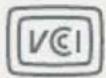 | Indicates the display is approved according to the VCCI regulations |
 | Indicates this apparatus must not be thrown in the trash but must be recycled, according to the European WEEE (Waste Electrical and Electronic Equipment) directive |
Legal disclaimer
Although every attempt has been made to achieve technical accuracy in this document, we assume no responsibility for errors that may be found. Our goal is to provide you with the most accurate and usable documentation possible; if you discover errors, please let us know.
Barco software products are the property of Barco. They are distributed under copyright by Barco N.V. or Barco, Inc., for use only under the specific terms of a software license agreement between Barco N.V. or Barco Inc. and the licensee. No other use, duplication, or disclosure of a Barco software product, in any form, is authorized.
The specifications of Barco products are subject to change without notice.
All trademarks and registered trademarks are property of their respective owners.
This document is copyrighted. All rights are reserved. Neither this document, nor any part of it, may be reproduced or copied in any form or by any means - graphical, electronic, or mechanical including photocopying, taping or information storage and retrieval systems - without written permission of Barco.
© 2011 Barco N.V. All rights reserved.
Technical specifications
MXRT-1150
| Bus compatibility Could be installed within PCI Express x1, x8, x16 mechanical slots Works in PCI Express x1, x4, x8, x16 electrical slots / operates at x1 speed | |
| Power consumption <25 Watt | |
| Form factor Low-profile, half-length (2.3"x 6.6") | |
| Operating system Windows® XP, X64, Vista | |
| Platforms Intel® and AMD architectures | |
| Graphics accelerator ATI FireMV™ | |
| Display memory 256 MB DDR2 | |
| Look up table 32 bits in / 32 bits out | |
| Pixel depth Up to 32 bit color | |
| Electrical standard DMS-59 to Dual DVI-I output | |
| Connectors DMS-59 to Dual DVI-I output | |
| Supported resolutions Analog: 2048x1536 Digital 1920x1200 per display VGA at boot-up | |
| Approvals | FCC Class B, CE, ICES-003, VCCI, BSMI, MIC, UL |
| Operating temperature | 0° to 55°C (32° to 131°F) |
MXRT-2150
| Bus compatibility Could only be installed within PCI Express x16 mechanical slot Works in PCI Express x4, x8, x16 electrical slots / operates at x16 speed | |
| Power consumption <25 Watt | |
| Form factor Low-profile, half-length (2.3"x 6.6") | |
| Operating system Windows® XP, X64, Vista | |
| Platforms Intel® and AMD architectures | |
| Graphics accelerator ATI FireMV (RV516 GPU) | |
| Display memory 256 MB DDR2 | |
| Look up table 32 bits in / 32 bits out | |
| Pixel depth 32 bit color | |
| Electrical standard Single Link DVI complying to v1.0 specification | |
| Connectors DMS-59 with dual DVI-I Cable | |
| Supported resolutions | Analog: 2048x1536 Digital 1920x1200 per display VGA at boot-up |
| Approvals | FCC Class B, CE, ICES-003, VCCI, BSMI, MIC, UL |
| Operating temperature | 0° to 55°C (32° to 131°F) |
| Connectivity | DMS-59 to dual DVI-I cable for dual DVI-I output (included) |
MXRT-2400
| Bus compatibility PCIe Gen2 x16 | |
| Power consumption 43 Watt | |
| Form factor 169.67mm (L) x 64.46mm (H) single PCIe slot wide | |
| Operating system Windows 7 - 32/64-bit | |
| Platforms Intel® and AMD architectures | |
| Graphics accelerator ATI FirePro | |
| Display memory 512 MB DDR3 | |
| Memory Interface 64-bit | |
| Memory bandwidth 14.4 GB/s | |
| Pixel depth 32-bit pixels (supports 8-bit and 10-bit per color channel) | |
| Electrical standard Dual Link DVI complying to v1.0 Display Port (DP) complying to v1.1a | |
| Direct3D hardware support Microsoft® DirectX v11.0, Vertex Shader 5.0, Pixel Shader 5.0 | |
| Supported resolutions Up to 6MP color and 10MP grayscale | |
| OpenGL hardware support | OpenGL 4.0 |
| Approvals and compliance | FCC Part 15 Class B, CE EN 55022 Limit B, EN 55024, UL-60950-1, BMSI CNS, CISPR- 22/24, IEC609050-1, VCCI, CSA C22.2, EU RoHS directive (2002/95/EC), Certificate of Information & Communication Equipment (Republic of Korea) |
| Operating temperature | 0° to 60°C (32° to 140°F) |
| Connectivity | Single-link Display Port (DP) to DVI-I adaptor cable (1-adaptor is included) |
MXRT-5200
| Bus compatibility PCI Express Gen2 x16 native support | |
| Power consumption < 75 Watt | |
| Form factor 98.4 x 228.6 x 15.9 mm (3.87" x 9.0" x 0.63") | |
| Operating system Windows® XP 32/64, Server 2003, 2008, Vista XPDM, WDDM | |
| Platforms Intel® and AMD architectures | |
| Graphics accelerator ATI FireGL (RV630 GPU) | |
| Display memory 512 MB GDDR4 | |
| Look up table 24-bits in / 24-bits out(8-bits per color channel) | |
| Pixel depth Standard: 8-bit gray, 24-bit colorHigh Dynamic Range: 10-bit gray, 30-bit color | |
| Electrical standard Dual Link DVI complying with v1.0 | |
| Connectors 2 DL DVI-I connectors | |
| Supported resolutions | Up to 3280 x 2048VGA at boot up |
| Approvals | FCC Part 15 Class B, CE, UL-60950-1, BMSI CNS, CISPR-22/24, VCCI, CSA C22.2, EU RoHS, MIC |
| Operating temperature | 0° to 55°C (32° to 131°F) |
MXRT-5400
| Bus compatibility PCIe Gen2 x16 | |
| Power consumption 72 Watt | |
| Form factor 230.53mm (L) x 98.34mm (H) single PCIe slot wide | |
| Operating system Windows XP - 32/64-bit, Windows 7 - 32/64-bit | |
| Platforms Intel® and AMD architectures | |
| Graphics accelerator ATI FirePro | |
| Display memory 1 GB GDDR5 | |
| Memory Interface 128-bit | |
| Memory bandwidth 64 GB/s | |
| Pixel depth 32-bit pixels (supports 8-bit and 10-bit per color channel) | |
| Electrical standard Dual Link DVI complying to v1.0 Display Port (DP) complying to v1.1a | |
| Direct3D hardware support Microsoft® DirectX v11.0, Vertex Shader 5.0, Pixel Shader 5.0 | |
| OpenGL hardware support OpenGL 4.0 | |
| Connectors | 1- DVI-I, 2- Display Port (DP) |
| Supported resolutions | Up to 6MP color and 10MP grayscale |
| Approvals and compliance | FCC Part 15 Class B, CE EN 55022 Limit B, EN 55024, UL-60950-1, BMSI CNS, CISPR- 22/24, IEC609050-1, VCCI, CSA C22.2, EU RoHS directive (2002/95/EC), Certificate of Information & Communication Equipment (Republic of Korea) |
| Operating temperature | 0° to 60°C (32° to 140° F) |
| Connectivity | Single-link Display Port (DP) to DVI-I adaptor cable (2 adaptors are included)Dual-link Display Port (DP) to DVI-I adaptor available from Barco; Part Number K9305101 |
MXRT-5450
| Bus compatibility PCIe Gen2 x16 | |
| Power consumption 72 Watt | |
| Form factor 230.53mm (L) x 98.34mm (H) single PCIe slot wide | |
| Operating system Windows XP - 32/64-bitWindows 7 - 32/64-bit | |
| Platforms Intel® and AMD architectures | |
| Graphics accelerator ATI FirePro | |
| Display memory 1 GB GDDR5 | |
| Memory Interface 128-bit | |
| Memory bandwidth 64 GB/s | |
| Pixel depth 32-bit pixels (supports 8-bit and 10-bit per color channel) | |
| Electrical standard Dual Link DVI complying to v1.0 Display Port (DP) complying to v1.1a | |
| Direct3D hardware support Microsoft® DirectX v11.0, Vertex Shader 5.0, Pixel Shader 5.0 | |
| OpenGL hardware support OpenGL 4.0 | |
| Connectors | 2- DVI-I |
| Supported resolutions | Up to 6MP color and 10MP grayscale |
| Approvals and compliance | FCC Part 15 Class B, CE EN 55022 Limit B, EN 55024, UL-60950-1, BMSI CNS, CISPR- 22/24, IEC609050-1, VCCI, CSA C22.2, EU RoHS directive (2002/95/EC), Certificale of Information & Communication Equipment (Republic of Korea) |
| Operating temperature | 0° to 60°C (32° to 140° F) |
MXRT-7300
| Bus compatibility PCI Express Gen2 x16 native support | |
| Power consumption 76 Watt | |
| Form factor 249 mm (L) x 111 mm (H) (9.8" x 4.375") single PCIe slot wide | |
| Operating system Windows®, XP 32/64 bit Server 2003, 2008 Vista, Windows 7 32/64 bit XPDM, WDDM | |
| Platforms Intel® and AMD architectures | |
| Graphics accelerator ATI FirePro (RV730 GL XTX GPU) | |
| Display memory 1GB GDDR3 | |
| Look up table 24-bits in / 24-bits out (8-bits per color channel) | |
| Pixel depth 24-bit / 30-bit (HDR mode) | |
| Electrical standard Dual-link DVI, DisplayPort complying to v1.0 specification | |
| Connectors 2- DisplayPort connectors, 1- DL DVI-I connector | |
| Supported resolutions Up to 3280 x 2048 (VGA at boot-up) | |
| Approvals | FCC Part 15 Class B, CE EN 55022 Limit B, EN 55024, UL-60950-1, BMSI CNS, CISPR-22/24, VCCI, CSA C22.2, EU RoHS directive (2002/95/EC), Certificate of Information & Communication Equipment (Republic of Korea) |
| Operating temperature | 0° to 55°C (32° to 131°F) |
MXRT-7400
| Bus compatibility PCIe Gen2 x16 | |
| Power consumption 138 Watt | |
| Form factor 281.29mm (L) x 98.53mm (H) single PCIe slot wide | |
| Operating system Windows 7 - 32/64-bit | |
| Platforms Intel® and AMD architectures | |
| Power connector One 2x3 power connector | |
| Graphics accelerator ATI FirePro | |
| Display memory 2 GB GDDR5 | |
| Memory interface 256-bit | |
| Memory bandwidth 128 GB/s | |
| Pixel depth | 32-bit pixels (supports 8 and 10-bit per color channel) |
| Electrical standard Dual Link DVI complying to v1.0 Display Port (DP) complying to v1.1a | |
| Direct3D hardware support Microsoft® DirectX v11.0, Vertex Shader 5.0, Pixel Shader 5.0 | |
| OpenGL hardware support | OpenGL 4.0 |
| Connectors | 1- DVI-I, 2- Display Port (DP) |
| Supported resolutions | Up to 6MP color and 10MP grayscale |
| Approvals and compliance | FCC Part 15 Class B, CE EN 55022 Limit B, EN 55024, UL-60950-1, BMSI CNS, CISPR- 22/24, IEC609050-1, VCCI, CSA C22.2, EU RoHS directive (2002/95/EC), Certificate of Information & Communication Equipment (Republic of Korea) |
| Operating temperature | 0° to 60°C (32° to 140° F) |
| Connectivity | Single-link Display Port (DP) to DVI-I adaptor cable (2 adaptors are included)Dual-link Display Port (DP) to DVI-I adaptor available from Barco; Part Number K9305101 |
Warranty statement
BARCO MID GENERAL WARRANTY TERMS AND CONDITIONS
Applicable from Jan 1st 2008
ARTICLE 1: PRODUCT WARRANTY
Barco nv, Medical Imaging Division warrants that the equipment will be free of defects in workmanship or material for the warranty period or the specific period of a warranty extension program.
Hardware: Barco warrants that upon delivery hereunder the Products shall (i) conform to its specifications in effect at the date of delivery and (ii) be free from defects in material and workmanship (the "Warranties").
Software: Barco warrants that software written by Barco shall perform substantially in accordance with the specifications in effect at the date of delivery. Software is inherently susceptible to bugs and errors. Barco makes no warranties with respect to the software which is provided to Customer on an "as-is" basis and does not warrant uninterrupted or error-free operation of the Products.
Unless otherwise indicated in Barco's Product manual or in the agreement between Barco and Customer, the Warranty Period shall be
(a) Hardware: 12 months commencing on the Barco date of invoice.
(b) Software: 3 months commencing on the Barco date of invoice.
Notwithstanding the provisions of clause 2, repair and replacement of defects in material and/or workmanship under this warranty shall be accomplished in our works according to the terms and conditions as set forth hereafter:
1.1 Any claim under the Warranties must be notified to Barco in writing within 8 days from the date the defect or failure has been discovered or noticed the first time. The Customer, upon the occurrence of any equipment failure, shall contact Barco nv, MID customer support centre (or an authorised service centre) by telephone, fax or e-mail and shall provide the applicable customer support person with a complete description of the problem being encountered, including the model and serial number of the equipment in which the problem has arisen.
1.2 The customer support person shall diagnose the problem experienced by the Customer and shall advise the Customer on how to proceed. Customer support may ask to return the faulty equipment or faulty subassemblies to the Barco ny, or a MID customer support centre (or an authorised service centre) for repair activities. In no event shall Customer return a defective Product or part thereof to Barco without Barco's prior written approval.
In the event the return to Barco of the defective Product is authorized by Barco, Barco shall issue to Customer an RMA (Return Material Authorization).
The Customer shall apply for an RMA number to the closest Barco nv, MID Customer support centre (or an authorised service centre) as listed at www.barcomedical.com, unless otherwise indicated.
The one-way cost of packing, transport and insurance related to shipping the alleged defective Product or part to Barco for repair or replacement shall be borne by Customer. The one-way cost of packing, transport and insurance related to shipping of the repaired or replacement Product or part to Customer shall be borne by Barco.
1.3 The Customer shall return, freight prepaid, the defective equipment or subassemblies in its original packaging with the assigned RMA number for repair to the Barco nv, MID Customer support centre (or an authorised service centre).
1.4 Replacement parts used shall be new or equivalent to new parts for the revision level of the equipment. A replacement LCD panel will be new or similar run time. The warranty period for the replacement parts will expire at the same moment as the original warranty period of the equipment. All parts replaced hereunder and returned to Barco nv, MID (or an authorised service centre) shall become the property of Barco nv, MID (or the authorised service centre).
1.5 The repaired equipment shall be returned to the Customer, by regular freight, at Barco nv, MID's charge.
1.6 Barco nv, MID will replace a product that fails within 90 days after shipment from Barco with a new one, ensuring color matching in the event of a diagnostic multi head display configuration.
Barco aims to ship the new replacement product within 2 business days after receipt of the Customers notification in writing.
ARTICLE 2: CONDITIONS PRECEDENT FOR WARRANTY AND ITEMS EXCLUDED FROM WARRANTY
A. The Warranties shall apply only to the extent the Products or any parts thereof have
(i) been transported and stored at all times in the original packaging in the conditions as specified by Barco (such as covered and secure location, minimum and maximum temperature, maximum humidity, ...) or, in absence thereof, at least in conditions consistent with generally accepted practice for this type of products;
(ii) been handled at all times in accordance with Barco's instructions or, in absence thereof, at least with the care and caution consistent with generally accepted practice for this type of products;
(iii)been installed strictly in accordance with the instructions and directions given by Barco (if and to the extent the
Products have not been installed by Barco or its authorized subcontractors);
(iv) not been subject to any unauthorized access, alteration, modification or repair or attempts thereto;
(v) been at all times "normally used" for the intended purpose and operated in strict accordance with the operating instructions set forth in the operating manual of the Product in question and shall not have been otherwise misused, abused, damaged. For the purpose hereof, "normally used" shall mean a regular, ordinary and routine usage of the Product in question as intended and/or recommended by Barco;
(vi)been maintained at all times in accordance with Barco's instructions or, in absence thereof, at least with intervals and in a manner consistent with generally accepted practice for this type of products;
B. The warranty described herein shall not include the following:
2.1 Any hardware or software item procured from a source other than Barco nv, MID or their official agent or distributor and integrated by Customer or a third party into Barco nv, MID supplied equipment.
2.2 Any host configuration not explicitly supported by Barco nv, MID.
2.3 All software installed on the system, whether they are acquired from Barco nv, MID or third party. An exception is made for software delivered by Barco nv, MID that would prove to be a cause for the mal functioning of the hardware covered under this Agreement.
2.4 Normal wear and tear, use under circumstances exceeding specifications, such as use in dusty environment or under excessive temperature conditions, abuse, unauthorised repair or alternation, lack of proper configuration or maintenance, damaged or modified or removed serial number, cosmetic refurbishment.
2.5 Repair or replacement of consumables 1 or specific parts that by definition are subject to wear and tear, including but not limited to:
a. CRT's, LCD panels
b. Backlights in diagnostic LCD displays, when the backlight run time 2 is beyond the Guaranteed Backlight Lifetime3 of that model, when used at the Factory Calibrated Luminance4
Eg1.
• A display is used at 8 hours/day; ie. +/-2.920hours/year
• The display system is covered with a warranty period of 5 year
• The Guaranteed Backlight Lifetime of that model is 17.000 hours.
• The Factory Calibrated Luminance cannot be achieved anymore after 4 year, thus corresponding to +/- 11.680 hours
• Result: the backlight replacement is performed under warranty
Eg2.
• A display is used at 24 hours/day; ie. 8.760hours/year
• The display system is covered with a warranty program of 5 year
• The Guaranteed Backlight Lifetime of that model is 17.000 hours.
• The Factory Calibrated Luminance cannot be achieved anymore after 2.5 years, thus corresponding to +/-21.900 hours
- Result: the backlight replacement does not make part of the warranty coverage.
(1): 'Consumable' is a part that can be replaced by the user
(2): 'Backlight run time' is the total time that an image (including use of a screen saver) has been applied to the screen; this value can be consulted via the OSD buttons (On Screen Display).
(3): 'Guaranteed Backlight Lifetime' is the number of backlight hours during which a predefined luminance value, ie. the Factory Calibrated Luminance, will be provided by a specific diagnostic display model. This figure is printed on the Warranty certificate of each display or can be requested at your local Barco office.
(4): 'Factory Calibrated Luminance': is the typical luminance value that a specific diagnostic display model is calibrated at during the production process. This figure is printed on the Warranty certificate of each display or can be requested at your local Barco office.
c. Lamps, optical components in projectors
d. Replacement because of:
i. image retention as a result of:
- not correctly using screen saver and/or Display Power Management System (DPMS) as explained in the user manual
- prolonged operation of the display with a static image on the same screen area
ii. a number of missing pixels that is lower than the total allowable number as mentioned in the product specifications.
iii. difference in color temperature that is lower than the total allowable difference as mentioned in the product specifications
iv. difference in color temperature as a result of not using all displays of a multi-head configuration at the same rate.
v. LCD luminance uniformity that is in within the product specifications or luminance uniformity performance that is inherent to LCD technology.
Barco nv, MID does not warrant a minimum life time nor a performance of any of the consumables.
2.6 Replacement of moveable parts such as power cords, remote controls, ...
2.7 Any product disassembly and installation costs at the operation site, travel expenses and travel time to and from the operation site for the personnel in charge of the repair works and transport charges.
2.8 Any failures resulting from an accident, negligence (such as but not limited to removing or deleting system files & licensed software product files), misuse, circuit failure or any change, damage due to fire, water, thunder or lightning, power failure or fluctuation, disruption of communication lines or due to force majeure, or any reason foreign to the equipment.
2.9 Any specific services or procedures, asked for by Customer, related to verification of repaired equipment.
2.10 The evaluation cost in case of a returned product deemed functional is not covered under warranty and will be charged to the Customer, at Barco's sole discretion, based on a case-by-case evaluation.
ARTICLE 3: OBLIGATIONS OF THE CUSTOMER
Customer hereby assumes the following obligations as partial consideration for Barco nv, MID performance of its requirements under the warranty condition; failure by Customer to meet its obligations under this paragraph shall excuse Barco nv, MID's performance hereunder:
3.1 Customer shall not expose Barco nv, MID personnel to any unsafe working conditions.
3.2 Repairs to equipment under warranty resulting from improper maintenance or repair performed by the Customer, or its officers, agents, employees, or representatives, shall be borne by the Customer at its additional cost and expense.
3.3 The Customer is responsible for installing the Barco nv, MID equipment in an environment for which it was intended. If there is an indication that the equipment was used – even temporary – outside its specifications, Barco nv, MID is entitled not to perform warranty repairs and terminate the warranty agreement. Any actions that have been taken by Barco nv, MID in this respect, may be invoiced to the Customer at normal pricing.
ARTICLE 4: REMEDIES UNDER WARRANTY
(a) Hardware: If during the Warranty Period a Product or any part thereof, fails to meet any of the Warranties then, upon Customer's request, Barco shall, at its sole option and cost, promptly and within 20 working days, either: (i) repair or correct the Product or part in question; or (ii) replace the Product or supply part(s) or component(s) according to the terms and conditions contained in article 1. A replacement part shall be at least functionally equivalent to the original part. The replaced Product, parts and/or components shall become the property of Barco and shall, at Barco's request, be returned by Customer to Barco at Barco's cost.
(b) Software: Barco's sole obligation shall be to rectify substantial malfunctions of the software (to the extent technically reasonably possible) by amending the software or supplying an alternative version of the software.
(c) The repair or replacement under the Warranties covers the cost of material and labor.
ARTICLE 5: DISCLAIMER OF WARRANTIES
BARCO NV, MID DISCLAIMS ALL WARRANTIES, EXPRESSED OR IMPLIED, INCLUDING ALL IMPLIED WARRANTIES OF MERCHANTABILITY AND FITNESS FOR A PARTICULAR PURPOSE.
ARTICLE 6: LIMITATION OF LIABILITY
The remedies specified in these Terms and Conditions shall constitute Customer's sole and exclusive remedy and Barco's sole and exclusive liability for Barco's breach of the Warranties hereunder.
BARCO NV, MID SHALL NOT UNDER ANY CIRCUMSTANCES BE LIABLE TO CUSTOMER OR ANY THIRD PARTY FOR DIRECT, INDIRECT, INCIDENTAL, SPECIAL OR CONSEQUENTIAL DAMAGES, SUCH AS BUT NOT LIMITED TO, DAMAGE TO OR LOSS OF TANGIBLE OR INTANGIBLE PROPERTY OR EQUIPMENT, LOSS OF PROFITS OR REVENUES, COST OF CAPITAL, COST OF PURCHASE OF REPLACEMENT GOODS, OR CLAIMS OF USER FOR SERVICE INTERRUPTIONS. THE LIABILITY OF BARCO NV, MID FOR MANUFACTURING, SALE, DELIVERY, RESALE, INSTALLATION, OPERATION OR SUITABILITY FOR USE OF ANY PRODUCTS OR SERVICES COVERED BY OR FURNISHED UNDER THIS WARRANTY CONDITION, WHETHER ARISING OUT OF CONTRACT, NEGLIGENCE, STRICT TORT, WARRANTY OR OTHERWISE, SHALL NOT EXCEED THE PRICE OF THE ITEM OR ITEMS OF GOODS OR SERVICES UPON WHICH SUCH LIABILITY IS BASED.
ARTICLE 7: FORCE MAJEURE
Either party shall be released from performance of its obligations under this agreement to the extent, and for so long as, the performance of this agreement is impeded by reason of force majeure. For the purposes of this clause the
expression "force majeure" means, but shall not be limited to, industrial dispute, fire, mobilisation, requisition, embargo, currency transfer prohibitions, insurrection, lack of means of transport, restrictions of the use of energy, and generally any circumstances which are beyond the control of the parties and hinder performance by one party of his obligations.
ARTICLE 8: GENERAL
8.1 Customer acknowledges its understanding that all software and electronic devices, including Barco nv, MID products are subject to possible error, mechanical or electrical failure, and should not be relied upon in inappropriate applications or without proper backup and/or other safety precautions whenever personal injury or property damage may result from failure or error of the product.
8.2 Barco nv, MID shall not be responsible for machine failure and/or its failure to render service or maintenance due to causes beyond its reasonable control.
(This page intentionally left blank.)
K5905271-00
May 2011
- Welcome!
- Table of contents
- What's in the box 7
- Display controller installation 9
- Dongles....15
- Driver and software installation 25
- Configuring Windows 31
- Important information 33
- What's in the box
- Display controller installation
- Which display controller?
- Installing a Barco display controller
- Overview
- TYPES OF DISPLAY CONTROLLERS FOR BARCO DISPLAY SYSTEMS
- Board Model Compatible PCIe Slot
- Which PCIe slot to use
- Installation Procedure
- CONNECTING YOUR BARCO DISPLAYS
- 10-Panel for the Barco MXRT 5200 & MXRT 5450
- IO-Panel for the Barco MXRT 5400, MXRT 7300, & MXRT 7400
- Dongles
- Single-Link dongle
- Dual-Link dongle
- Common cases
- MXRT 2400
- MXRT 5400
- MXRT 7400
- Driver and software installation
- Driver and software installation prerequisites
- Installing the BARCO MXRT drivers and software
- Automated display configuration
- Reinstalling drivers
- Uninstalling the drivers and software
- Silent Installation of Drivers and Software
- Configuring Windows
- Setting the resolution of your BARCO DISPLAY CONTROLLER
- Accessing the Windows Display Control Panel
- Configuring Windows Theme
- Configuring Clone (duplicate) Mode
- Configuring Software Rotation
- Important information
- Environmental information
- DISPOSAL INFORMATION (WASTE ELECTRICAL AND ELECTRONIC EQUIPMENT)
- TURKEY ROHS COMPLIANCE
- Regulatory compliance information
- FCC CLASS B
- Explanation of symbols
- Legal disclaimer
- Technical specifications
- MXRT-1150
- Warranty statement
- BARCO MID GENERAL WARRANTY TERMS AND CONDITIONS
- ARTICLE 1: PRODUCT WARRANTY
- ARTICLE 2: CONDITIONS PRECEDENT FOR WARRANTY AND ITEMS EXCLUDED FROM WARRANTY
- ARTICLE 3: OBLIGATIONS OF THE CUSTOMER
- ARTICLE 4: REMEDIES UNDER WARRANTY
- ARTICLE 5: DISCLAIMER OF WARRANTIES
- ARTICLE 6: LIMITATION OF LIABILITY
- ARTICLE 7: FORCE MAJEURE
- ARTICLE 8: GENERAL
Brand : Barco
Model : FirePro V5800
Category : Video card