
FirePro MXRT-1450 - Video card Barco - Free user manual and instructions
Find the device manual for free FirePro MXRT-1450 Barco in PDF.


User questions about FirePro MXRT-1450 Barco
0 question about this device. Answer the ones you know or ask your own.
Ask a new question about this device
Download the instructions for your Video card in PDF format for free! Find your manual FirePro MXRT-1450 - Barco and take your electronic device back in hand. On this page are published all the documents necessary for the use of your device. FirePro MXRT-1450 by Barco.
USER MANUAL FirePro MXRT-1450 Barco
natural_image
Red FirePro 3D graphics card with Huawei logo and power drive fan (no text or symbols on card body)UserGuide
Windows7andWindows8.1
Barco nv
President Kennedypark 35, 8500 Kortrijk, Belgium
Phone: +32 56.23.32.11
Fax: +32 56.26.22.62
Support: www.barco.com/esupport
Visit us at the web: www.barco.com
TABLEOFCONTENTS
1. Welcome!....3
1.1 About the product 3
1.2 What's in the box....3
2. Display Controller installation....5
2.1 Which Display Controller? 5
2.2 Installing a Barco Display Controller 5
2.3 Installation procedure....6
2.4 Connecting your Barco Displays 7
3. Dongles 9
3.1 Passive Single-Link Dongle 9
3.2 Active Single-Link Dongle....9
3.3 Dual-Link Dongle....10
3.4 Common cases....11
4.Driver and software installation....23
4.1 Driver and software installation prerequisites....23
4.2 Installing the Barco MXRT drivers and software....23
4.3 After installation 25
4.4 Silent installation of drivers and software....28
5. Configuring Windows 31
5.1 Configuring SingleView....31
5.2 Configuring Barco Displays with the Windows Display Control Panel....31
5.3 Configuring software rotation 31
6. Conference CloneView....33
6.1 What is Conference CloneView? 33
6.2 Configuration 33
6.3 Notification icon 34
6.4 Tools available on the cloned display 35
7. Important information....37
7.1 Safety information....37
7.2 Environmental information 37
7.3 Regulatory compliance information 39
7.4 Explanation of symbols....39
7.5 Legal disclaimer....41
7.6 Technical specifications 41
1.WELCOME!
1.1 About the product
DisplayController
ThankyouforchoosingthisBarcoDisplayController!
Barco'sstate-of-the-artDisplayControllersdelivertheperformance,qualityandstabilityr requiredforto-day'sadvancedmedicalimagingapplications. Thepowerfulboardsensureultra-fastandsmoothimage loading,roamingandmanipulationofimagesineveryresolution.
UsetheinstructionsinthisguidetoinstallyourBarcoDisplayController.
1.2 What'sinthebox
Contents
YourBarcoDisplayControllercomeswith:
•ThisBarcoDisplayControllerUserGuide
•2Single-LinkDonglesareincludedwiththeMXRT-4500,MXRT-5400,MXRT-5500,MXRT-7400&MXRT-7500.
• 1 Single-Link Dongle and 1 low-profile bracket are included with the MXRT-2400 & MXRT-2500.
- 1 DMS-59-to-DVI adapter cable and 1 low-profile bracket are included with the MXRT-1450 & MXRT-1451.

Keep your original packaging. It is designed for this Display Controller and is the ideal protection during transport and storage.
2.DISPLAYCONTROLLERINSTALLATION
2.1 Which DisplayController?
DisplayControllerrange
YourBarcomedicaldisplayiscompatiblewithalargerangeofBarcoandnon-BarcoDisplayController boards. Dependingontheorderdetails, thedisplaycanbedeliveredwithorwithoutaDisplayController.
If you are installing a Barco Display Controller, please follow the installation instructions in this section. If you are installing an on-Barcodisplay controller, please consult its corresponding document.
2.2 InstallingaBarcoDisplayController
Guidance
ThischapterwillguideyouthroughthephysicalinstallationofaBarcoDisplayControllerforyourdisplay system.

WARNING: Wear a grounded, protective ESD strap when handling or during installation of the DisplayController. ElectrostaticchargescandamagetheDisplayController.
Overview
Prior to installing the Barco Display Controller(s) for your Barco Display System in your workstation, please takeafewminutestofamiliarizeyourselfwiththeDisplayController(s)andthePCleslots.
Types of Display Controllers for Barco Display Systems
The following models of Barco Display Controllers are available for your display system. Please check whichofthefollowingmodelsisdeliveredwithyoursystemandfollowthecorrespondinginstallationinstructions:
| BarcoModel | CompatiblePCIeSlot |
| BarcoMXRT-1450 | x1 1, x8, x16 |
| BarcoMXRT-1451 | x1 1, x8, x16 |
| BarcoMXRT-2400 | x16 |
| BarcoMXRT-2500 | x16 |
| BarcoMXRT-4500^2 | x16 |
| BarcoMXRT-5400 | x16 |
| BarcoMXRT-5450 | x16 |
| BarcoMXRT-5500 | x16 |
| BarcoMXRT-5550 | x16 |
| BarcoMXRT-7400 | x16 |
| BarcoMXRT-7500 | x16 |
WhichPCleslottouse
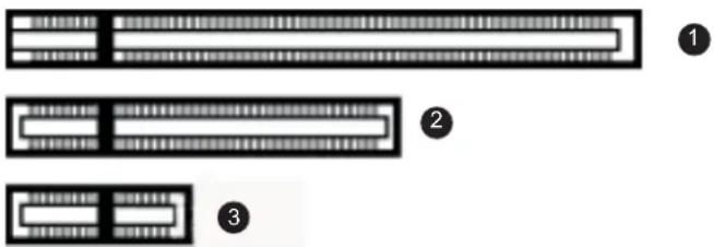
ThetableaboveliststhevariousDisplayControllermodel(s)availableforyourBarcoDisplaySystemand the recommended PCIe slot to use for optimum performance. The figure below shows the different types ofPCIeslotsthatcanbeused.
natural_image
Three abstract rectangular shapes with horizontal and vertical patterns, labeled 1, 2, and 3 (no text or symbols on shapes)Image2-1
ExamplesofPCIeslots
1 x16slot
2 x8slot
3 x1slot
2.3 Installation procedure
Howtoinstall
The following instructions will take you step by step through the installation of the BarcoDisplayController(s) for your BarcoDisplaySystem.
-
If you are not going to use your old Controller, uninstall its drivers and software.
Warning: Wear a grounded, protective ESD strap when handling or during installation of the Display Controller. ElectrostaticchargescandamagetheDisplayController. -
Turnoff the computer, display(s), and other peripheral devices.
-
Unplugthecomputer's powercord and disconnectallcables from the back of your computer.
Warning: Wait approximately 20 seconds after unplugging the power cord before disconnecting a peripheralorremovingaccomponentfromthemotherboardtoavoidpossibledamagetothe motherboard.
-
Removethecomputercover. If necessary, consult your computer's manual for instructions.
-
If necessary, unscrewor unfasten and remove any existing display controller(s) from your computer.
Tip: If you are using a motherboard containing an on-board graphics solution and do not intend to use it as part of a multiple-display setup, disable either in the computer's System Set-up utility (BIOS) or the Windows device manager.
-
Locatetheappropriateslotand, if necessary, removethemetalback-platecover(s).
-
AligntheBarcoDisplayController(s)foryourBarcoDisplaySystemwiththeslot(s)andpressit(them) in firmly until the card(s) is(are) fully seated.
Tip: ThenextstepappliesonlytotheMXRT-7400&MXRT-7500.
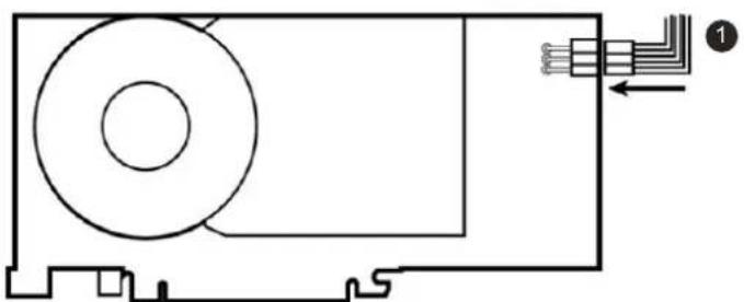
- Connect the power cable to the 6-pin power connection on the Display Controller. Makes sure the cables are not interfering with anything inside the computer (fore example, a cooling fan).
natural_image
Pure electrical circuit lines without any symbolsImage2-2 PowerconnectionfortheMXRT-7400&MXRT-7500controllers
1 6-pingraphicscontrollerpowercable
- Screw in or firmly fasten the Display Controller. Replace and secure the computer cover.
2.4 Connecting your Barco Displays

Foradetaileddescriptionofthedisplayinstallationandsignalconnection, pleaserefer totheDisplayUserGuide.
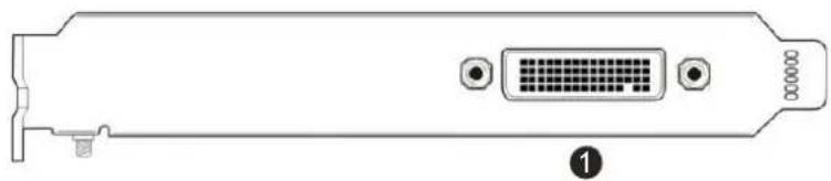
IO-PanelfortheBarcoMXRT-1450&MXRT-1451
natural_image
Diagram of a computer RAM card rear panel with D-sub connector and ports (no text or labels)Image2-3 MXRT-1450&MXRT-1451
DMS-59connectorprovidesDVI-I/Head1&Head2outputconnectionsthroughincludedthe Y-adaptercable.
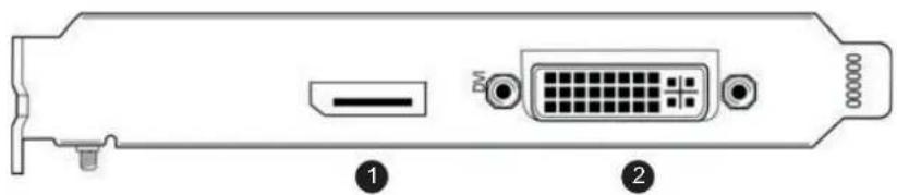
IO-PanelfortheBarcoMXRT-2400&MXRT-2500
natural_image
Diagram of a computer RAM drive rear panel showing port, socket, and cable (no text or labels)Image2-4 MXRT-2400&MXRT-2500
1 DisplayPortConnection
2 DVI-IPConnection
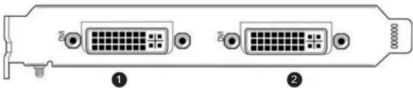
IO-PanelfortheBarcoMXRT-5450&MXRT-5550
natural_image
Diagram of a computer RAM module showing two connected ports with indicator lights (no text or labels)Image2-5
MXRT-5450&MXRT-5550
1 Head1-DVI-IConnection
② Head2-DVI-ICConnection
IO-PanelfortheBarcoMXRT-4500, MXRT-5400, MXRT-5500&MXRT-7400
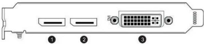
Image2-6
MXRT-4500, MXRT-5400, MXRT-5500&MXRT-7400
1 DisplayPort#1
② DisplayPort#2
③ DVI-I
IO-PanelfortheBarcoMXRT-7500
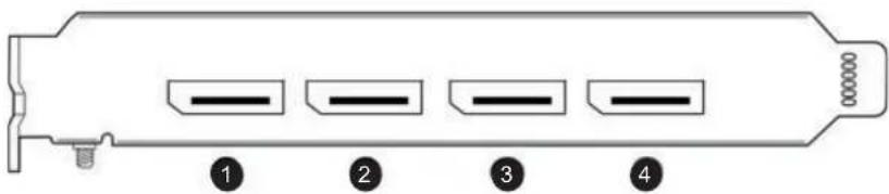
Image2-7
MXRT-7500
1 DisplayPort#1
② DisplayPort#2
③ DisplayPort#3
4 DisplayPort#4
FordplayswithnativeDisplayPortinput,useanativeDisplayPortcabletoconnecttheDisplayPortoutput oftheDisplayControllertotheDisplayPortinputofthedisplay.YoucannotconnecttheDVIoutputofa DisplayControllertotheDisplayPortinputofadisplay.
3.DONGLES

BarcodonglesarespeciallydesignedtoallowBarcoDisplayControllerswithaDisplay-PortoutputtobeconnectedwithadisplaywithDVInput.

Ifvideocableconversionisnotrequired,youmaybypassthissection.
3.1 PassiveSingle-LinkDongle
PassiveSingle-Link
ThepassiveSingle-LinkDongleallowsyoutoconnectadisplay'sDVInputtotheDisplayPortoutputof yourBarcoDisplayController.ItiscompatiblewithallBarcograyscaledisplaysandupto2MPcolor models.Forcolordisplaysof3MPandgreaterresolutions,theDual-L inkDongleisnecessary.

AllBarcoDisplayControllerscompatiblewiththeDisplayPortinterfacecomewithaSingle-LinkDonglebydefault.

natural_image
Close-up of a USB connector with two connected cables (no text or symbols visible)Image3-1
Single-Linkdongle(suppliedwithsystem)
1 Todisplay(Single-LinkDVI)
2 ToDisplayPortconnectoronBarcoDisplayController
3.2 ActiveSingle-LinkDongle
ActiveSingle-Link
BarcoDisplayControllersarenotcompatiblewithactivesingle-linkdongles.PleaseusethepassivedonglesthatareincludedwithyourBarcoDisplayControllers.
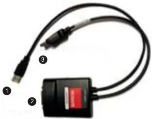
3.3 Dual-LinkDongle
Dual-Link
TheactiveDual-LinkDonglealsoconvertsDisplayPortinputsignalstoDVIoutputsignals. However, unlike thepassiveSingle-Linkdongle,theDual-Linkdongleallowshigherresolutions(greaterthan1920x1200) oncolordisplays.

WARNING: A Dual-Link DVI cable must be used to connect your display's DVI connector with the DVI connector on the Dual-Link Dongle.

TheDual-Linkdongleisorderedseparately.
Usethefollowingstepstoinstallthedongle:
- ConnecttheDisplayPortendoftheconnectortotheDisplayController.
natural_image
Close-up of a black USB cable with three labeled connectors (1, 2, 3), no visible text or symbols on the device itself.Image3-2
Dual-Linkdongle(orderedseparately)
1 Tocomputer'sUSBport
② Todisplay(DVIDual-Link)
3 ToDisplayPortconnectoronBarcoDisplayController
2.PluginaDual-LinkDVIcablefromthedisplaytotheDVIportofthedongle.
3. Connectthebuilt-inUSBpowercableonthedongletoaworkstationUSBport.
4. If you are using QAWebAgent version 1.10.2 or older, a separate software component is required for supporting DDC communication through the Dual-Link dongle. Run setup ex from Barco_DLDP2DVI Install package after driver installation to install the SW.
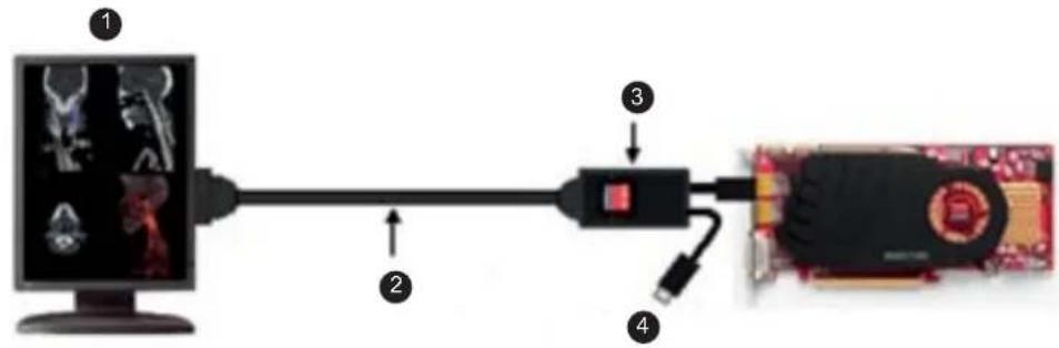
Image3-3 Dual-LinkDongleinstallation
1 Upto3MPcolor
2 9'BarcoDVIcable
3 Dual-LinkDPtoDVIadapter
4 USBpowerconnector
3.4Commoncases
MXRT-2400&MXRT-2500
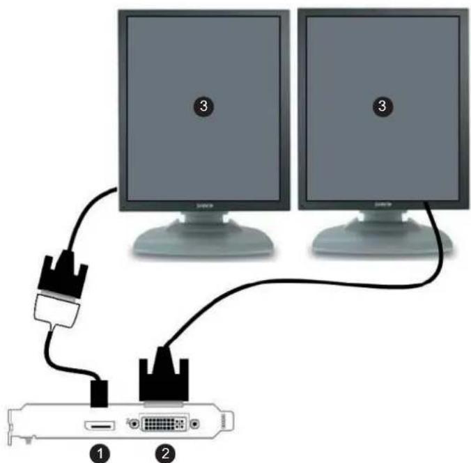
Image3-4 Allgrayscaleor2MPcolordiagnosticdisplays
1 DisplayPortconnectionwithsingle-linkdongle
2 DVI-Icon connection
3 GrayscalediagnosticdisplayorColor2MPdiagnosticdisplay
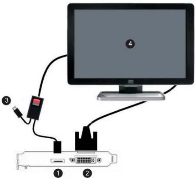
Image3-5
DVI6MPColorDiagnosticdisplayor3MPColordisplay
1 DisplayPortconnectionwithdual-linkdongle
② DVI-Icon connection
3 USBpowertocomputer
4 DVI6MPColorDiagnosticdisplayor3MPColordisplay
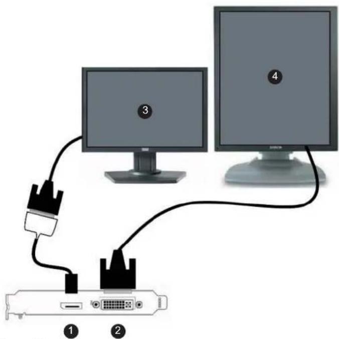
Image3-6
DVIColorNavigationdisplayandanyGrayscaleor2MPColorDiagnosticdisplay
1 DisplayPortconnectionwithsingle-linkdongle
2 DVI-Icon connection
3 DVIColorNavigationdisplay
4 Grayscaleor2MPColorDiagnosticdisplay
MXRT-4500, MXRT-5400, & MXRT-5500
DVINavigationdisplayandallGrayscaleor2MPColorDiagnosticdisplays
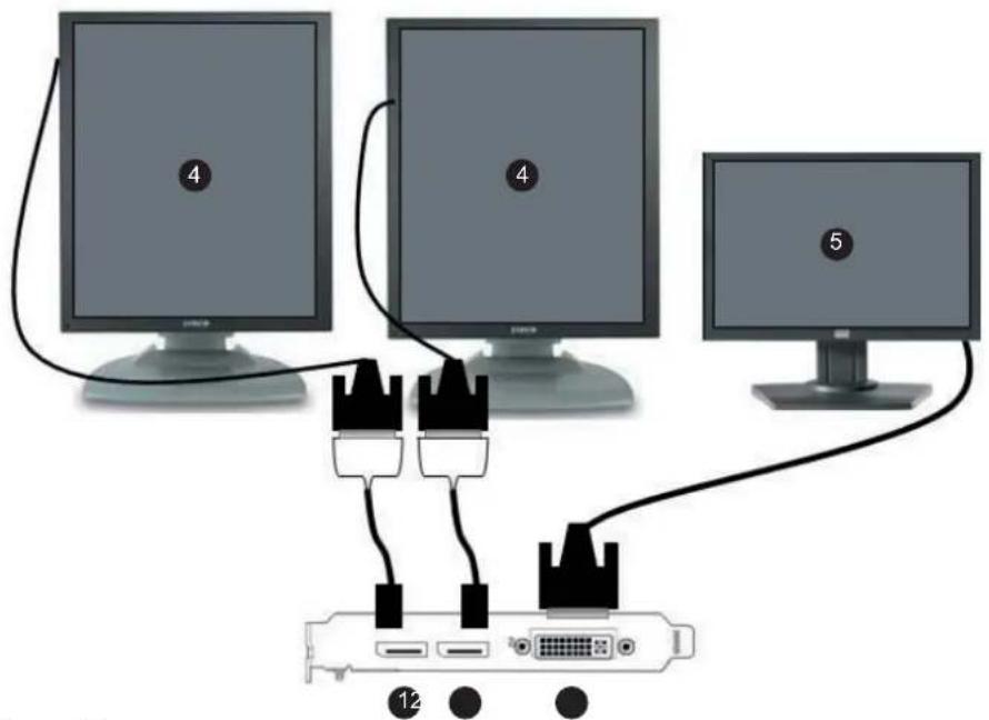
Image3-7
DVINavigationdisplayandallGrayscaleor2MPColorDiagnosticdisplays
1 DisplayPortwithsingle-linkdongle
2 DisplayPortwithsingle-linkdongle
③ DVI-I
4 GrayscaleDiagnosticdisplayor2MPColorDiagnosticdisplay
5 ColorNavigationdisplay
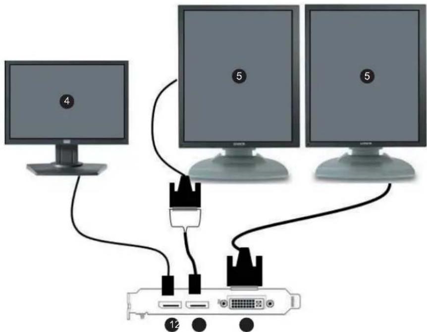
Image3-8
DisplayPortNavigationdisplayandallGrayscaleor2MPColorDiagnosticdisplays
1 DisplayPort#1
2 DisplayPortconnectionwithsingle-linkdongle
③ DVI-I
4 ColorNavigationdisplay
5 GrayscaleDiagnosticdisplayor2MPColorDiagnosticdisplay
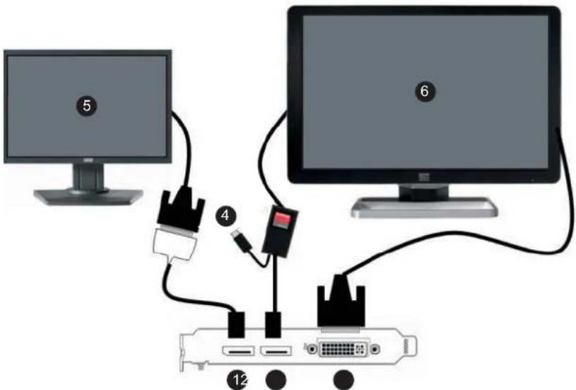
Image3-9 DVINavigationdisplayand6MPColorDiagnosticdisplayor3MPColordisplays
1 DisplayPortconnectionwithsingle-linkdongle
2 DisplayPortconnectionwithdual-linkdongle
③ DVI-I
4 USBpowertocomputer
5 ColorNavigationdisplay
6 6MPColorDiagnosticdisplayor2x3MPColordisplays
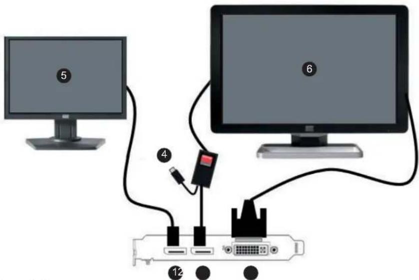
Image3-10 DisplayPort Navigation display and 6MP Color Diagnostic display or 3MP Color displays
1 DisplayPort#1
2 DisplayPortconnectionwithdual-linkdongle
③ DVI-I
4 USBpowertocomputer
5 ColorNavigationdisplay
6 6MPColorDiagnosticdisplayor2x3MPColordisplays
MXRT-7400
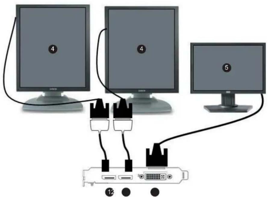
Image3-11
DVI Navigation display and all Grayscale or 2MP Color Diagnostic displays (see Tip)
1 DisplayPortconnectionwithsingle-linkdongle
2 DisplayPortconnectionwithsingle-linkdongle
3 DVI-I
4 GrayscaleDiagnosticdisplayor2MPColorDiagnosticdisplay
5 ColorNavigationdisplay
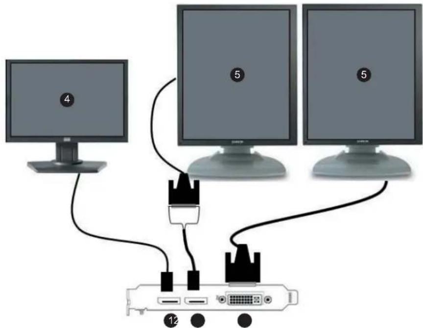
Image3-12
DisplayPortNavigationdisplayandallGrayscaleor2MPC olorDiagnosticdisplays(seeTip)
1 DisplayPort#1
2 DisplayPortconnectionwithsingle-linkdongle
③ DVI-I
4 ColorNavigationdisplay
5 GrayscaleDiagnosticdisplayor2MPColorDiagnosticdisplay

Diagnosticdisplaysmusthavematchingresolutions.
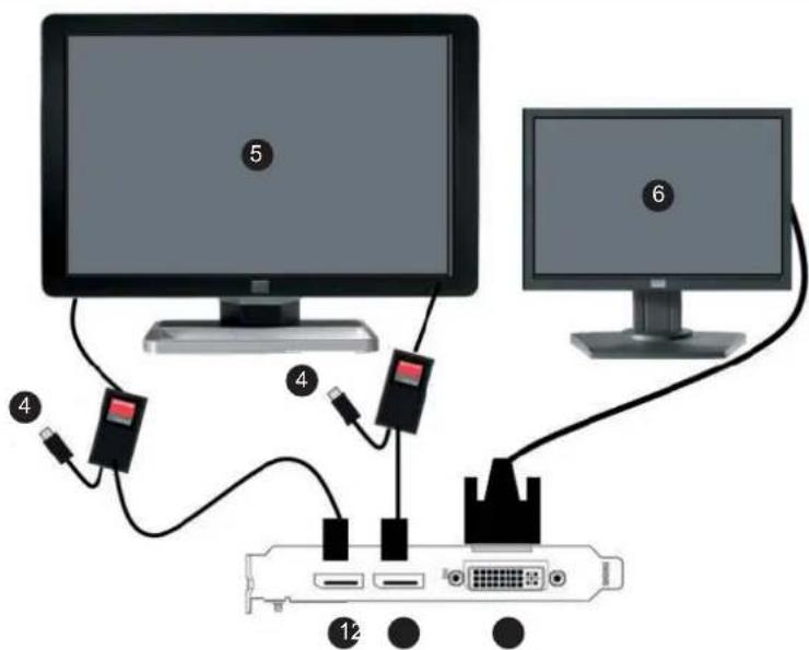
Image3-13
DVINavigationdisplayand6MPColorDiagnosticdisplayor3MPColordisplays
1 DisplayPortconnectionwithdual-linkdongle
2 DisplayPortconnectionwithdual-linkdongle
③ DVI-I
4 USBpowertocomputer
5 6MPColorDiagnosticdisplayor2x3MPColordisplays
6 ColorNavigationdisplay
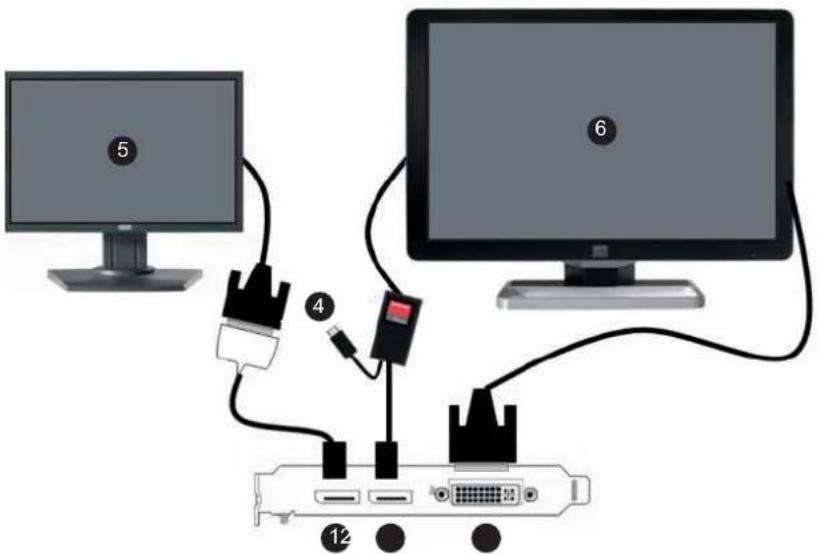
Image3-14 DisplayPort Navigation display and 6MP Color Diagnostic display or 3MP Color displays
1 DisplayPortconnectionwithsingle-linkdongle
2 DisplayPortconnectionwithdual-linkdongle
③ DVI-I
4 USBpowertocomputer
5 ColorNavigationdisplay
6 6MPColorDiagnosticdisplayor2x3MPColordisplays
MXRT-7500
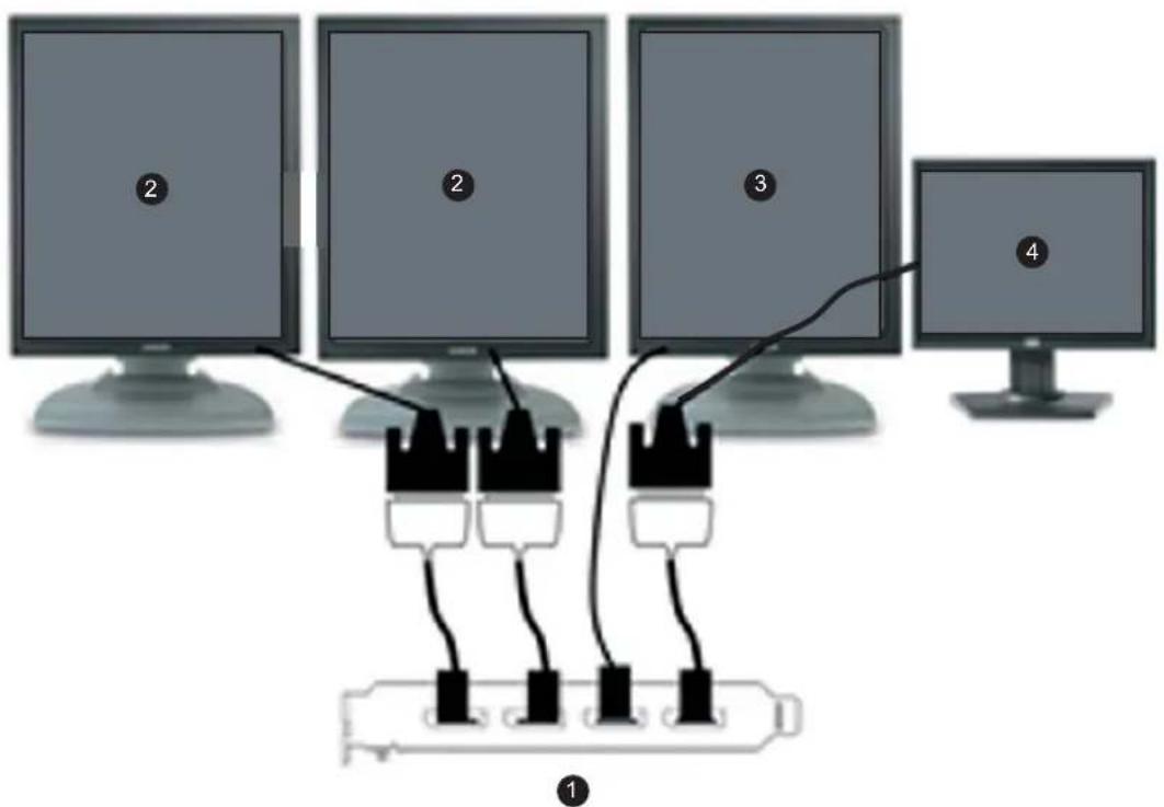
Image3-15
DVI Navigation display and Dual-head DVI Grayscale displays with an optional DisplayPort 3D display (see Tip).
1 DisplayPort#1through#4
2 GrayscaleDiagnosticdisplay(DVI)
3 3DDisplay(DP):thisisoptional
4 ColorNavigationdisplay

TheGrayscaleDiagnosticdisplaysmusthavematchingresolutions.
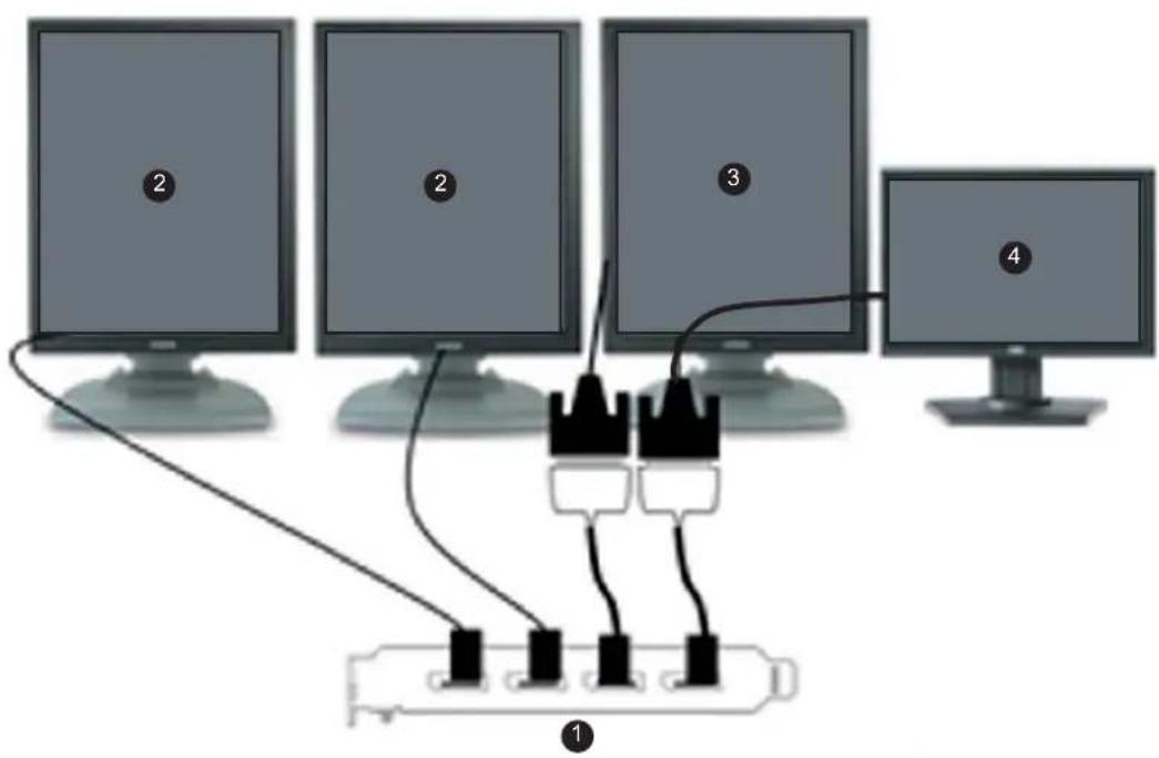
Image3-16
DVINavigationdisplayandDual-headDisplayPortGra yscaledisplayswithanoptionalDVI3Ddisplay
1 DisplayPort#1through#4
2 GrayscaleDiagnosticdisplay(DP)
3 3DDisplay(2MPColorDVI):thisisoptional
4 ColorNavigationdisplay
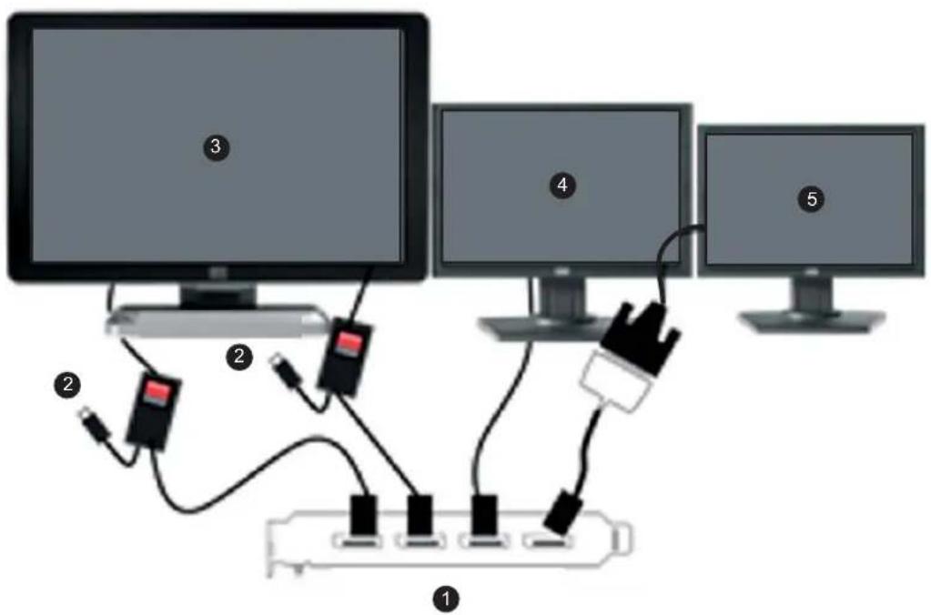
Image3-17
DisplayPortNavigationdisplayandDVI6MPColorDiag nostic display or 3MP Color displays with an optional third DVI display
1 DisplayPort#1through#4
2 USBpowertocomputer
3 6MPColorDiagnosticdisplayor2x3MPColorDiagnosticDVI(e.g.MDCC-6130)
4 ColorNavigationdisplay(DP)
5 ColorNavigationdisplay(DVI):thisisoptional
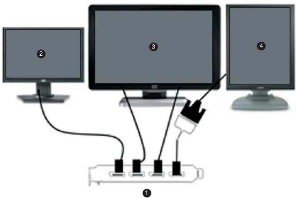
Image3-18
DisplayPortNavigationdisplayandDisplayPort6MPC olorDiagnosticdisplayor3MPColordisplayswithanoptionalDVI3Ddisplay
1 DisplayPort#1through#4
2 ColorNavigationDPdisplay(e.g.MDRC-2124)
3 6MPColorDiagnosticdisplayor2x3MPColorDiagnosticDPdisplay(e.g.MDCC-6230)
4 3DDisplay(2MPColorDVI):thisisoptional
4.DRIVERANDSOFTWARE INSTALLATION
4.1 Driver and software installation prerequisites
Prerequisites

Toinstallorremovethedrivers,software,ordocumentationyoumustbeloggedonas auserwithadministratorprivileges.
Youroperatingsystemmustbeinstalledandrunningbeforeyoucaninstallthedriver,softwareanddocumentationfortheBarcoDisplayController(s)foryourBarcoDisplaySystem.
Before you begin, makes sure that all of your Barco Displays are connected to the appropriate Display Controller(s) in your system.
4.2 InstallingtheBarcoMXRTdriversandsoftware
Introduction
Thischapterwillguideyouthroughtheinstallationofthedriver withyourBarcoDisplaySystemorBarcoDisplayController(s).
s,softwareanddocumentationassociated

TheinstallationdialogwilldisplayinEnglishifyouroperatingsystem'slanguageisnot supported.
This process applies to the following versions of Windows:
- Windows732-bit
- Windows764-bit
- Windows8.132-bit
- Windows8.164-bit

For optimal system performance, Barco recommends installing no more than two drivers on a system at one time. If the configuration will require three drivers, the Barco DriverInstallerwillalerttheusertoreplaceoneboardtoeliminateoneofthedrivers.
YouwillneedtoinstalltheBarcoDisplayControllersystemdriversandsoftwareinthefollowingcases:
- After you have installed the BarcoDisplayController(s) for your BarcoDisplaySystem in your system for the first time.
- Afteryouhavereinstalledorupgradedyouoperatingsystem.
- WhenyouupgradetoanewerverersionoftheMXRTdriverandsoftware.
Youdonotneedtomanuallyuninstallanexistingdriverbeforeupdatingtothecurrentversion.The BarcoProductInstallationWizardwilldetectanypriorinstallationsandstarttheuninstallationprocess automaticallyifnecessary.
If you have a previous version of Conference Clone View application installed in the system, you need to terminate the application prior to installing the new version. To do so, bring up Barco Clone Display(s) configuration window, select Stop Cloning, and close the window.
When there is a non-Barco board in the system, we recommend that you first install the driver for the non-BarcoboardbeforeinstallingtheBarcodriver.
After each driver installation, you should reboot the system before proceeding with the installation of another driver.
Installationprocedure
The following will guide you through the installation procedure:
1.Startyoursystem.IfyouhaveafreshOSinstallation,oryouhaveuninstalledanexistingdriver,the OSmayautomaticallyinstallaninboxdriverfromtheWindows7driverstore,eitheranAMDdriveror astandardVGAdriver,fortheBarcoDisplayController(s). If this occurs, the OS prompts you to restart your computer, click Yes to allow the automatic driver installationtocompleteandrebootthesystem.
2. LaunchtheBarcoProductInstallationWizard.TheinstallationWizardshouldstartautomaticallywhen youinserttheBarcoDisplaySystemInstallationDVDintoyourcomputer'sDVDdrive.Iftheinstallation does not start, in the "auto play" window, click Run setup.exe.
3. To accept the installation of default software components, click on Next. To custom select software components, click on Select Software Components and the following screen will appear, allowing selection of individual components.
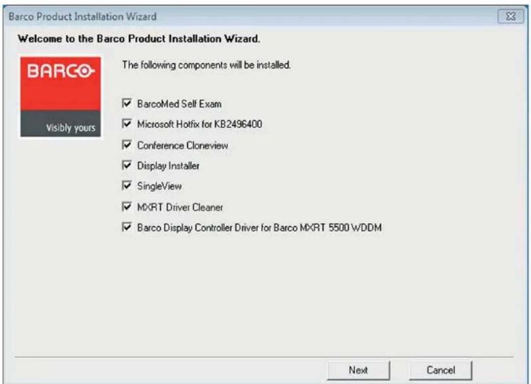
Image4-1
Softwarecomponentoptionsforcustominstallation
- M X R T d r i v e r ( s )
-BarcoMedSelfExam:Barcodiagnostictool
-QAWebAgent:Barcocalibrationsoftware2
- SingleView: This application is required to configure Barco Fusion displays into SingleView mode orbackintoDualViewmode.InSingleView,thedisplayhasasinglelandscaperesolution,andin DualView,ithastwoside-by-sideportraitresolutions.
-ConferenceCloneView: An application that allows the user to clone 1 or 2 display to third display, such as a projector.
-DriverCleaner: An application that will remove all Barcosoftware components from your workstation.
- Display Installer: This file allows Windows to recognize Barco displays.
- Microsoft Hotfix for KB2496400: Resolved the issue that monitor configuration is lost after you restart acomputerthatisrunningWindows7.
In a configuration that includes an MXRT-1150/2150 and other MXRT boards, two separate drivers will be installed. Themasterinstallationprogramwillmaketwopassesthroughthedriverinstallation process(i.e.LicenseAgreement,VerifyInstallationOptions,etc.).
-
If a previous installation of an MXRT driver exists, the installation wizard will detect it and guide you through the uninstallation process if necessary.
-
Click Yes to accept the driver's License Agreement, and then Next to continue.
-
You will be prompted for Express or Custom Installation. By default, the Express Install option is selected. Custom Installation prompts two installation options:
- 30-bit Desktop: This option allows high dynamic range visualization of medical imaging on grayscale and color displays.
- SingleView: This option sets all Barco Fusion displays into SingleView mode.
-
During installation, the desktop may flash, and the Installation Wizard window may appear on different displays. This is expected behavior.
-
Whentheinstallationofallcomponentshascompleted, theautomaticrebootwindowwillb edisplayed. Allow thesystemtoreboot.
4.3 Afterinstallation
Installationverification
To verify that the driver was installed, go to the Windows Control Panel, select System, select Device Manager, then select Display Adapters. Verify that Barco Display Controllers are properly identified, as shown below:
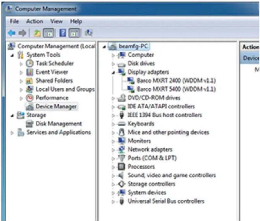
Image4-2 Verifyingdriverinstallation
Automaticdisplayconfiguration
Oncethedrivers, softwareanddocumentationhavebeeninstalledandyoursystemhasbeenrebooted, thecomputershouldautomaticallydetectyourBarcodisplaysandattachthemtothedesktopwiththe correctresolution. IfthecomputerfailstodetectyourBarcodisplaysorfailstoattachthemtothedesktop correctly, please use the Windows Screen Resolution to set the correct resolution.
Reinstallingdrivers
Youcaninstallnewdriversorreinstalle existingdriversatanytimebyusingtheBarcoSet-upwizardon yourBarcoDisplaySystemInstallationDVD.
Uninstallingthedriversandsoftware
TouninstalltheBarcodrivers,softwareordocumentationforyourBarcoDisplaySystem,pleaseusethe Windows Add/Remove Programs. This can be found in the Windows Control Panel under Programs & Features.
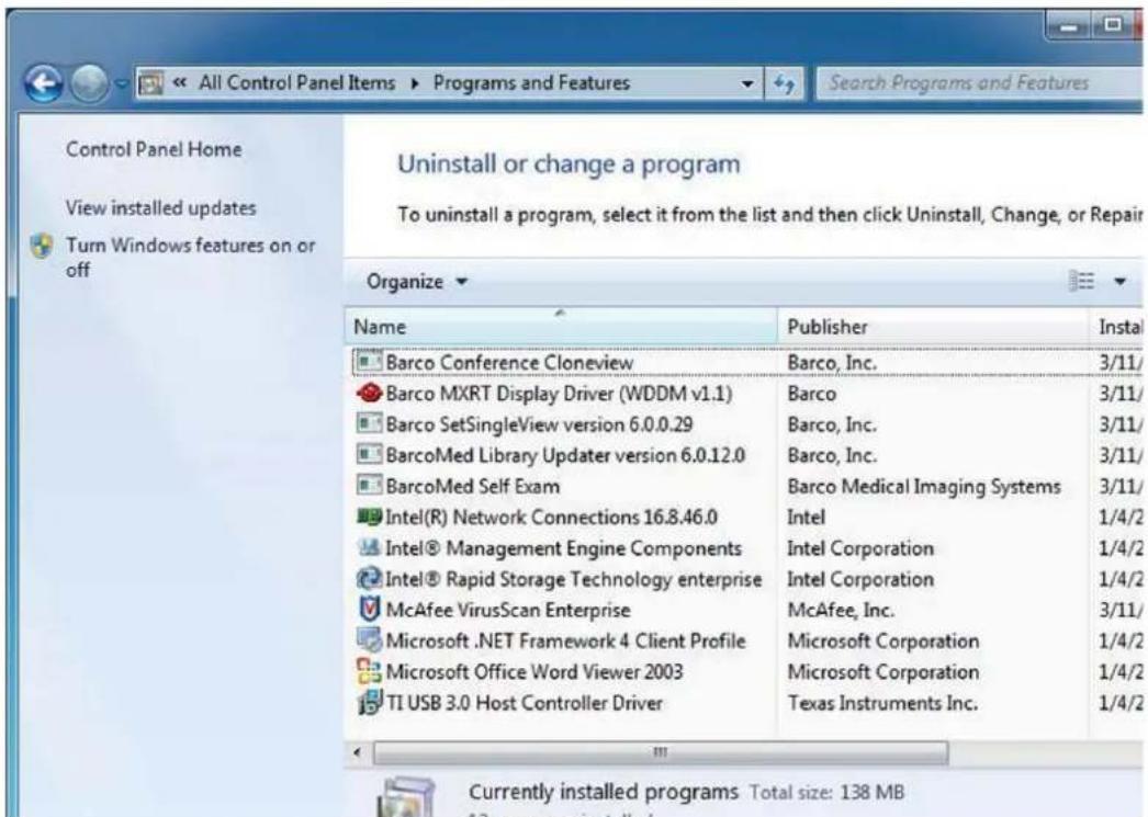
Image4-3
Windows7Add/RemovePrograms

When uninstalling the BarcoMXRT drivers, the following dialog box will appear. Select the driver listed you wish to install (driver version may be different than what is pictured below).
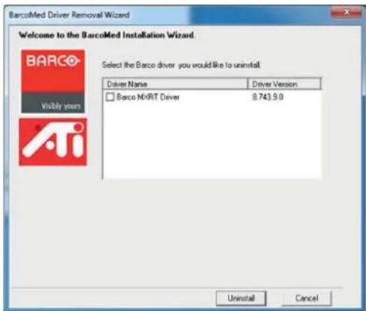
Image4-4
BarcoMXRTDriverRemovalWizard
DriverCleaner
The Barco Driver Cleaner is a tool that will remove all Barco software components from your workstation. The application and its user guide can be found at C:\program files\Barco.
4.4Silentinstallationofdriversandsoftware
Pre-installation
OnceaBarcodriverhasbeenpre-loadedintothedriverstoreofaWindows7OS,subsequentinstallation ofthedriverwillbeintervention-free.
Topre-loadthedriversoftwareintothedriverstore, openacommandshellandnavigatetotheappropriate driverdirectoryandrunthePnPUtilapplicationwiththe-a"add"parameter.Forexample:
cdd:\Barco\drivers\VS32\MXRT
pnputil-a*.inf
The PnPUtil application will parse the inf files and add the MXRT drivers to the driver store.
If this is the first installation of a Barco driver, the trust prompt will ask whether you really want to install the driver. Check the box that says Always trust software from Barco and press OK. The PnPUtil application will confirm the driver is loaded into the driver store.
Atthispointyoucanchangetoanotherdirectoryandrepeatthiswithotherdrivers.Youwillnotseethe trustprompt.
If you install using wildcards, you may see an error message that the Autorun.in format. This message is normal and can be ignored.
When you have added allofthedriversthatyouwillneedtothedriverstore,youcancreateanimageof thedrive,anduseitforstagingadditionalsystems.Allofthesystemswiththisdriverstorearesetupfor intervention-freesilentinstallation.
Silentinstallation
For silent installation, first import the Barco published certificate into the certificate store. This certificate can be extracted from the driver catalog file located in the driver package. Pleasenotethatthecertificate changesovertime, sowerecommendextractingthecurrentoneeachtime.
Once imported, navigate to the Barco installation folder and execute the command setup.exe -silent. This can be done from the command shell, from the Run command, or from a command shortcut. The setupprogramwillautomaticallyinstallthedriversforanyBarcoMedorMXRTboardsthatarepresent, theBarcoMedSelfExamprogram,andQAWeb(ifpartoftheinstallationpackage).
Configuresilentinstalloptions
You can modify the setup.ini file at the Barco root folder to customizesomesilentinstalloptions. The configurable options are listed in the [Custom] section of the setup.ini file.
SimplifiedFinishPage:
• If set to Yes, only the Finish button appears on the final installation page.
- IfNo(default),rebootbuttonsandshowdocumentcheckboxesarealsoshown.
Reboot:
- If set to Yes (default), the installer will prompt the user or launch a timer to reboot following software installation.
• IfNo, theprompt/timerisnotshown.
DisableCalibrationSoftwareText:
• IfsettoYes(default), QAWebsoftwareisinstalled.
- IfNo, theusercanselectinstallationofeitherQAWeband/orMediCalPro, ifpresent.
IgnoreInstallFailureOnReboot:
• If set to Yes, the system will disregard any installation failures and proceed to auto-reboot.
- IfNo(default), theauto-bootisdisableifinstal lationfailuresaredetected.
DisableQAWebScripts:
- IfsettoYes, QAWebwillauto-start.
- IfNo(default),scriptswillpreventQAWebfromlaunchinguntilafterthereboot.
- IfsettoYes, the installer will not require the usertouninstallpreviousBarcodrivers.
- IfNo(default),theinstallerpromptstheusertouninstallpre-existingdrivers.
NeverForceUninstall:
5. CONFIGURING WINDOWS
5.1ConfiguringSingleView
HowtoconfigureSingleView
- From the StartMenu, select All Programs.
- Under the Barco Programs folder, select the desired configuration:
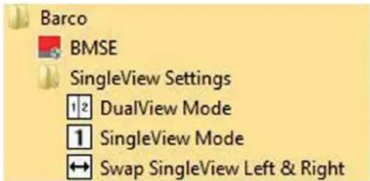
Image5-1
SingleViewStartMenuoptions

When your Fusion display is configured in SingleView mode, it is possible that the left andrightsidesoftheimagearenotinthecorrectorder.Inthiscase,clickontheSwap SingleViewLeft&Rightoption,anditwilladjusttheheadsonthedesktop.
5.2ConfiguringBarcoDisplayswiththeWindowsDisplayControlPanel
HowtodisplaytheWindowsdesktop
- Rightclickonthedesktop, and select Screenresolution.
- From the Windows Display Control Panel, highlight the Barcodisplay whose mode you wish to set, and select Advanced settings.
- In the Adapter tab of the Advanced settings dialog box, click on the List All Modes button.
- SelecttheresolutionandrefreshratethatyourBarcoDisplayControllersupportsfromthedialogbox andclickOK.
- ClickOKonthebottomoftheAdaptercontrolpanel.
- Click Yes in the "Do you want to keep these display settings?" dialog box. Your Barco Display Controller shouldnowsynchronizeanddisplaytheWindowsdesktop.
5.3 Configuring software rotation
Howtochangeyourscreenorientation
Softwarerotationisonlynecessaryfordisplaysthatdonotsupporthardwarerotation,suchasMDRC displaysandsomethirdpartydispla ys.
- Right click on the Desktop, and select Screen Resolution in the context menu.
2.SelectaDisplay.
3. In the Orientation dropdownlist, these options are available:
-Landscape(norotation)
-Portrait(rotate90degrees)
-Landscape(flipped)
-Portrait(flipped)
- Select the desired setting, and click Apply.
6. CONFERENCECLONEVIEW
6.1 What is Conference Clone View?
Overview
Thisapplicationallowstheusertocloneoutputsfrom1or2displaystoathirddisplayorprojectorattached to the same Display Controller. The cloned image will be scaled to fit the resolution of the target display. The applicationsupportszoomingandpanningforeaseofviewing.
SupportedDisplayControllers
MXRT-1450&MXRT-1451, MXRT-2400, MXRT-2500, MXRT-4500, MXRT-5400, MXRT-5450, MXRT-5500, MXRT-5550, MXRT-7400&MXRT-7500.
6.2Configuration
Howtoconfigureyourdisplay(s)
- Start the Conference CloneView application either from the desktop icon or from Start -> Programs -> Barco, this will display the configuration window.
- SelecttheDisplayControllerthatisconnectedtothedisplay(s)y o u w o u l d i k e t o c l o n e f r o m t h e d r c down list. You can only clone displays connected to the same Display Controller. Click on Identify to seethedisplaysconnectedtothecurrentlyselectedDisplayController.
- Selectuptotwosourcedisplay(s)toclonefrom, and the target display where the cloned image will display, and click on the Create Clone button. By default, the source image(s) will be downscaled to fit the cloned display, while maintaining the original aspect ratio. Select Stretch to fill to stretch the cloned image to fit the cloned display's resolution, ignoring aspect ratio.
- Once all desired cloning has been configured, you may close the configuration window. The selected cloning configuration will persist during reboots until the user elects to stop cloning.
- To stop cloning, click on the Stop Cloning button in the configuration window. Alternatively, right click on the cloned display and select Stop Cloning from the context menu.
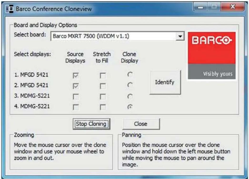
Image6-1
ConferenceCloneViewconfigurationwindow
6.3 Notificationicon
Systemtray
The Conference CloneView notification icon is available in the system tray once the Conference CloneView application has been launched. Right clicking on the icon offers the following menu options:
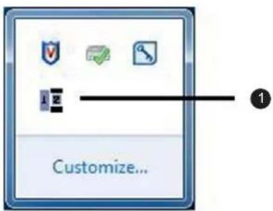
Image6-2
ConferenceCloneViewnotificationicon
1 Notificationicon
• Show GUI: This launches the configuration window.
- Start when Windows starts: When checked, the clone configuration is restored upon every reboot.
- Pause cloning: This will stop updating the cloned images on each cloned display, essentially freezing the current images. Uncheckthistocontinuelive updates.
- Exit: This stops the application. To restart it, launch the Conference CloneView application from the StartMenu.
6.4 Tools available on the cloned display
Whenthemousecursorisovertotheclonedimage, it will changetoadifferentshape and the following control options are available:
Zoomingandpanning
Theusercanzoominontheclonedimagebyrollingthemousecursorwheel.
Whenzoomedin, the cloned imagery may be bigger than the cloned display and part of the image may be offscreen. Click and hold the left mouse button and mov the cursor to top the portion of the image that is offscreen.
Clonedisplaymenuoptions
RightclickingontheclonedimagewillbringuptheConferenceCloneViewcontextmenu.
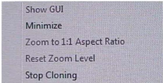
Image6-3 ConferenceCloneViewcontextmenu
Menuoptions:
- Show GUI: This option launches the configuration window. When the configuration window is already shown, this option is grayedout.
- Minimize: This minimizes the cloned image to show the desktop.
- Zoom to 1:1 Aspect Ratio: When "Stretch to fill" is selected in the configuration window, the aspect ratio of the cloned image may not match the source. Select this option to zoom directly to a 1:1 aspect ratio. When "Stretch to fill" is not selected, this option is grayed out.
- Reset Zoom Level: Select this option to return to the minimize zoom level. When the image is already atheminimumzoomlevel, thisoptionisgrayedout.
- Stop Cloning: Select this option to stop cloning on the current Display Controller. It has the same effect as clicking on the Stop cloning button in the configuration window.
7. IMPORTANT INFORMATION
7.1 Safetyinformation
General recommendations
Readthesafetyandoperatinginstructionsbeforeoperatingthedevice.
Retainsafety and operating instructions for further reference.
Adheretoallwarningsonthedeviceandintheoperatinginstructionsmanual.
Followwallinstructionsforoperationanduse.
ElectricalShockorFireHazard
To prevent electric shock or fire hazard, do not remove cover.
No serviceable parts inside. Refer servicing to qualified personnel.
Donotexposethisapparatustorainormoisture.
Modificationstotheunit:
Donotmodifythisequipmentwithoutauthorizationofthemanufacturer.
Typeofprotection(Electrical)
Devicewithexternalpowersupply:Classlequipment.
Degreeofsafety(flammableanestheticmixture):
Equipment not suitable for use in the presence of a flammable anesthetic mixture with air or with oxygen ornitrous oxide.
ThisDisplayControllerconformsto:
FCC Part 15 Class B, CE EN 55022 Limit B, EN 55024, UL-60950-1, BMSI CNS, CISPR-22/24, IEC609050-1, VCCI, CSA C22.2, EU RoHS directive (2002/95/EC), Certificate of Information & CommunicationEquipment(RepublicofKorea).
7.2 Environmental information
DisposalInformation
WasteElectricalandElectronicEquipment

This symbol on the product indicates that, under the European Directive 2012/19/EU governing wastefromelectricalandelectronicequipment,thisproductmustnotbedisposedofwithothermunicipal waste. Please dispose of your waste equipment by handing it over to a designated collection point for the recycling of waste electrical and electronic equipment. To prevent possible harm to the environment or humanhealthfromuncontrolledwastedisposal,pleaseseparatetheseitemsfromothertypesofwaste andrecyclethemresponsiblytopromotethesustainablereuseofmaterialresources.
For more information about recycling of this product, please contact your local city office or your municipal wasted disposalservice.
Fordetails, please visit the Barcowebsite at: h ttp://www.barco.com/en/AboutBarco/weee
TurkeyRoHScompliance

[RepublicofTurkey:InconformitywiththeWEEERegulation]
中国大陆 RoHS(EXAMPLE)
ChineseMainlandRoHS
According to the "China Administration on Control of Pollution Caused by Electronic Information Products" (Alsocalled RoHSofChinese Mainland), the table below lists these names and content so toxic and/or hazardous substances that Barco's product may contain. The RoHSofChinese Mainland is included in the MCV standard of the Ministry of Information Industry of China, in these section "Limit Requirements of toxic substances in Electronic Information Products".
| 零件项目(名称)Componentname | 有毒有害物质或元素Hazardoussubstancesandelements | |||||
| 铅Pb | 汞Hg | 镉Cd | 六价铬Cr6+ | 多溴联苯PBB | 多溴二苯醚PBDE | |
| 印制电路配件PrintedCircuitAssemblies | x | o | o | o | o | o |
| O:表示该有毒有害物质在该部件所有均质材料中的含量均在 SJ/T 11363-2006 标准规定的限量要求以下.O:IndicatesthatthistoxicorhazardoussubstancecontainedinallofthehomogeneousmaterialsforthispartisbelowthelimitrequirementinSJ/T11363-2006. | ||||||
| X:表示该有毒有害物质至少在该部件的某一均质材料中的含量超出 SJ/T 11363-2006 标准规定的限量要求.X:IndicatesthatthistoxicorhazardoussubstancecontainedinatleastoneofthehomogeneousmaterialsusedforthispartisabovethelimitrequirementinSJ/T11363-2006 | ||||||
AllElectronicInformationProducts(EIP)thataresoldwithinChineseMainlandmustcomplywiththe "ElectronicInformationProductsPollutionControlLabelingStandard"ofChineseMainland,markedwith theEnvironmentalFriendlyUsePeriod(EFUP)logo. ThenumberinsidetheEFUPlogothatBarcouses (pleaserefertothephoto)isbasedonthe"StandardofElectronicInformationProductsEnvironmental FriendlyUsePeriod"ofChineseMainland.

7.3 Regulatory compliance information
FCCclassB
This device complies with Part 15 of the FCC Rules. Operation is subject to the following two conditions: (1) this device may not cause harmful interference, and (2) this device must accept any interference received, including interference that may cause undesired operation.
ThisdevicehasbeentestedandfoundtocomplywiththelimitsforaClassBdigitaldevice,pursuantto Part15oftheFCCRules.Theselimitsaredesignedtoprovidereasonableprotectionagainstharmful interferenceinaresidentialinstallation.Thisdevicegenerates,usesandcanradiateradiofrequency energyand,ifnotinstalledandusedinaccordancewiththeinstructions,maycauseharmfulinterference toradiocommunications.However,thereisnoguaranteethatinterferencewillnotoccurinaparticular installation.Ifthisdevidedoescauseharmfulinterferencetoradioortelevisionreception,whichcanbe determinedbyturningthedeviceoffandon,theuserisencouragedtotrytocorrecttheinterferenceby oneormoreofthefollowingmeasures:
•Reorientorrelocatethereceivingantenna.
- Increase these separation between the device and receiver.
- Connectthedeviceintoanoutletonacircuitdifferentfromthattowhichthereceiverisconnected.
- Consultthedealeroranexperiencedradio/TVtechnicianforhelp.
Changes or modifications not expressly approved by the party responsible for compliance could void the user's authority to operate the equipment.
7.4 Explanationofsymbols
Symbolsonthedevice
On the device or power supply, you may find the following symbols (nonrestrictive list):
 | IndicatescompliancewiththeDirective93/42/EECasClassldevice |
 | IndicatescompliancewiththeDirective93/42/EECasClassIldevice |
 | |
 | IndicatescompliancewithPart15oftheFCCrules(ClassAorClassB) |
 | IndicatesthedeviceisapprovedaccordingtotheULregulations |
 | IndicatesthedeviceisapprovedaccordingtotheULregulationsforCanada andUS |
 | IndicatesthedeviceisapprovedaccordingtotheULDemkoregulations |
 | IndicatesthedeviceisapprovedaccordingtotheCCCregulations |
 | IndicatesthedeviceisapprovedaccordingtotheVCCIregulations |
 | IndicatesthedeviceisapprovedaccordingtotheKCregulations |
 | IndicatesthedeviceisapprovedaccordingtotheBSMIregulations |
 | IndicatestheUSBconnectorsonthedevice |
 | IndicatestheDisplayPortconnectorsonthedevice |
 | Indicatesthemanufacturingdate |
 | Indicatesthetemperaturelimitations ^3 forthedevicetosafelyoperatewithinspecs |
 | Indicatesthdeviceserialno. |
 | Warning:dangerousvoltage |
 | Caution |
 | Consulttheoperatinginstructions |
| [XCCS] | Indicatethisdevicemustnotbethrowninthetrashbutmustberecycled, accordingtotheEuropeanWEEE(WasteElectricalandElectronicEquipment) directive |
 | IndicatesDirectCurrent(DC) |
 | IndicatesAlternatingCurrent(AC) |
 | Stand-by |
 | Equipotentiality |
7.5 Legaldisclaimer
Disclaimernotice
Although every attempt has been made to achieve technical accuracy in this document, we assume responsibility for error that may be found. Our goalist provide you with the most accurate and usable documentation possible; if you discover errors, please let us know.
BarcosoftwareproductsarethepropertyofBarco. TheyaredistributedundercopyrightbyBarcoN.V. or Barco, Inc., for use only under the specific terms of a software license agreement between Barco N.V. or Barcolnc.andthelicensee.Nootheruse,duplication,ordisclosureofaBarcosoftwareproduct,ina ny form,isauthorized.
The specifications of Barco products are subject to change without notice.
Trademarks
Alltrademarksandregisteredtrademarksarepropertyoftheirrespectiveowners.
Copyrightnotice
Thisdocumentiscopyrighted.Allrightsarereserved.Neitherthisdocument,noranypartofit,may bereproducedorcopiedinanyformorbyanymeans-graphical,electronic,ormechanicalincluding photocopying,tapingorinformationstorageandretrievalsystems-withoutwrittenpermissionofBarco.
©2014BarcoN.V.Allrightsreserved.
Patentinformation(EXAMPLE)
Thisproductiscoveredunderthefollowingintellectualpropertyrights:
USPatentRE43,707
USPatent7,038,186
USPatent7,166,829
USPatent6,950,098
EuropeanPatent1274066.
7.6 Technical specifications
MXRT-1450
| ProductacronymMXRT-1450 | |
| Buscompatibility | CouldbeinstalledwithinPCIExpressx1,x8,x16mechanicalslotsWorksinPCIExpressx1,x4,x8,x16electricalslots/operatesatx1speed |
| Powerconsumption17Watt | |
| FormfactorLowprofile,half-length,2.3"x6.6" | |
| Operating system | Windows XP - 32/64-bit, Windows 7 - 32/64-bit, Windows 8.1 – 32/64-bit |
| Platforms | Intel®andAMDarchitectures |
| Graphicsaccelerator | ATI FirePro |
| Graphicsmemory | 512MBDDR3 |
| Memoryinterface | 64-bit |
| Memorybandwidth | 9.6GB/s |
| Pixeldepth | 32-bitcolor |
| Electricalstandard | Single-link DVI complying to v1.0 specification |
| ConnectorsDMS-59 | |
| ConnectivityOneDMS-59-to-DVI | adaptorincluded |
| Supportedresolutions2560x1600 | DisplayPort,1920x1200DVI/Analog |
| DirectXsupport | Microsoft®DirectXv11.0 |
| OpenGLsupportOpenGL4.0 | |
| OpenCLsupportOpenCL1.0 | |
| Approvalsandcompliance | FCCPart15ClassB,CEEN55022LimitB,EN55024,UL-60950-1,BMSICNS,CISPR-22/24,IEC609050-1,VCCI,CSAC22.2,EUROHS directive (2002/95/EC), Certificate of Information & Communication Equipment(RepublicofKorea) |
| Operatingtemperature0°to60°C | (32°to140°F) |
MXRT-1451
| ProductacronymMXRT-1451 | |
| Buscompatibility | CouldbeinstalledwithinPCIExpressx1,x8,x16mechanicalslotsWorksinPCIExpressx1,x4,x8,x16electricalslots/operatesatx1 speed |
| Powerconsumption17Watt | |
| FormfactorLowprofile,half-length | ,2.3"x6.6" |
| Operating system | Windows XP - 32/64-bit, Windows 7 - 32/64-bit, Windows 8.1 - 32/64-bit |
| Platforms | Intel®andAMDarchitectures |
| Graphicsaccelerator | ATI FirePro |
| Graphicsmemory | 1GBDDR3 |
| Memoryinterface | 64-bit |
| Memorybandwidth | 9.6GB/s |
| Pixeldepth | 32-bitcolor |
| Electricalstandard | Single-link DVI complying to v1.0 specification |
| ConnectorsDMS-59 | |
| ConnectivityOneDMS-59-to-DVI | adaptorincluded |
| Supportedresolutions2560x1600 | DisplayPort,1920x1200DVI/Analog |
| DirectXsupport | Microsoft®DirectXv11.0 |
| OpenGLsupportOpenGL4.0 | |
| OpenCLsupportOpenCL1.0 | |
| Approvalsandcompliance | FCCPart15ClassB,CEEN55022LimitB,EN55024,UL-60950-1,BMSICNS,CISPR-22/24,IEC609050-1, VCCI, CSAC22.2,EUROHS directive (2002/95/EC), Certificate of Information & Communication Equipment(RepublicofKorea) |
| Operatingtemperature0°to60°C | (32°to140°F) |
MXRT-2400
| ProductacronymMXRT-2400 | |
| Buscompatibility | PCIeGen2x16 |
| Powerconsumption43Watt | |
| Formfactor169.67mm(L)x64.46mm(H)singlePCleslotwide | |
| Operating system | Windows XP - 32/64-bit, Windows 7 - 32/64-bit, Windows 8.1 – 32/64-bit |
| Platforms | Intel®andAMDarchitectures |
| Graphicsaccelerator | ATI FirePro |
| Graphicsmemory | 512MBDDR3 |
| Memoryinterface | 64-bit |
| Memorybandwidth | 14.4GB/s |
| Pixeldepth | 32-bitpixels(supports8-bitand10-bitpercolorchannel) |
| ElectricalstandardDual-linkDVIcomplyingtov1.0,DisplayPortcomplyingtov1.1a | |
| Connectors | 1-DVI-I,1-DisplayPort |
| ConnectivityOneDisplayPorttoSingle-LinkDVI-Idongleincluded | |
| Supportedresolutions | Upto6MPcolorand10MPgrayscale |
| DirectXsupport | Microsoft®DirectXv11.0,VertexShader5.0,PixelShader5.0 |
| OpenGLsupportOpenGL4.0 | |
| OpenCLsupportOpenCL1.0 | |
| Approvalsandcompliance | FCCPart15ClassB,CEEN55022LimitB,EN55024,UL-60950-1,BMSICNS,CISPR-22/24,IEC609050-1,VCCI,CSAC22.2,EURoHS directive (2002/95/EC), Certificate of Information & Communication Equipment(RepublicofKorea) |
| Operatingtemperature0°to60°C(32°to140°F) | |
MXRT-2500
| ProductacronymMXRT-2500 | |
| Buscompatibility | PCIeGen2x16 |
| Powerconsumption50Watt | |
| Form factor 168 mm (L) x 68 mm (H) single PCleslotwide | |
| OperatingsystemWindows7–32/64-bit, Windows8.1–32/64-bit | |
| Platforms | Intel®andAMDarchitectures |
| Graphicsaccelerator | ATI FirePro |
| Graphicsmemory | 1GBDDR3 |
| Memoryinterface | 128-bit |
| Memorybandwidth | 28.8GB/s |
| Pixeldepth | 32-bitpixels(supports8-bitand10-bitpercolorchannel) |
| Electrical standard | Dual-link DVI complying to v1.0, DisplayPort complying to v1.2 |
| Connectors | 1-DVI-I,1-DisplayPort |
| ConnectivityOneDisplayPorttoSingle-LinkDVI-Idongleincluded | |
| Supportedresolutions | Upto6MPcolorand10MPgrayscale |
| DirectXsupport | Microsoft®DirectXv11.0,VertexShader5.0,PixelShader5.0 |
| OpenGLsupportOpenGL4.2 | |
| OpenCLsupportOpenCL1.1 | |
| Approvalsandcompliance | FCCPart15ClassB,CEEN55022LimitB,EN55024,UL-60950-1,BMSICNS,CISPR-22/24,IEC609050-1,VCCI,CSAC22.2,EUROHS directive (2002/95/EC), Certificate of Information & Communication Equipment(RepublicofKorea) |
| Operatingtemperature0°to60°C(32°to140°F) | |
MXRT-4500
| ProductacronymMXRT-4500 | |
| Buscompatibility | PCIeGen2.1x16 |
| Powerconsumption75Watt | |
| Form factor 163 mm (L) x 97 mm (H) single PCleslotwide | |
| OperatingsystemWindows7-32/64-bit, Windows8.1–32/64-bit | |
| PlatformsIntel®andAMDarchitectures | |
| Graphicsaccelerator | ATIFirePro |
| Graphicsmemory1GBGDDR5 | |
| Memoryinterface | 128-bit |
| Memorybandwidth | 64GB/s |
| Pixeldepth | 32-bitpixels(supports8-bitand10-bitpercolorchannel) |
| ElectricalstandardDual-linkDVI | complyingtov1.0, DisplayPortcomplyingtov1.2 |
| Connectors | 1-DVI-I,2-DisplayPort |
| ConnectivityTwoDisplayPorttoS | single-LinkDVI-IdonglesincludedDisplayPorttoDual-LinkDVI-IdongleavailablefromBarco;PartNumberK9305104 |
| Supportedresolutions | Upto6MPcolorand10MPgrayscale |
| DirectXsupport | Microsoft®DirectXv11.0, VertexShader5.0, PixelShader5.0 |
| OpenGLsupportOpenGL4.1 | |
| OpenCLsupport | OpenCL 1.1 |
| Approvalsandcompliance | FCCPart15ClassB, CEEN55022LimitB, EN55024, UL-60950-1,BMSICNS,CISPR-22/24, IEC609050-1, VCCI, CSAC22.2, EUROHS directive (2002/95/EC), Certificate of Information & Communication Equipment(RepublicofKorea) |
| Operatingtemperature | 0° to 60°C (32° to 140°F) |
MXRT-5400
| Productacronym | MXRT-5400 |
| Buscompatibility | PCIeGen2x16 |
| Powerconsumption | 72Watt |
| Formfactor | 230.53mm(L)x98.34mm(H)singlePCleslotwide |
| OperatingsystemWindowsXP-32/64-bit,Windows7-32/64-bit,Windows8.1–32/64-bit | |
| PlatformsIntel®andAMDarchitectures | |
| Graphicsaccelerator | ATIFirePro |
| Graphicsmemory1GBGDDR5 | |
| Memoryinterface | 128-bit |
| Memorybandwidth | 64GB/s |
| Pixeldepth | 32-bitpixels(supports8-bitand10-bitpercolorchannel) |
| Electricalstandard | Dual-linkDVIcomplyingtov1.0,DisplayPortcomplyingtov1.1a |
| Connectors | 1-DVI-I,2-DisplayPort |
| ConnectivityTwoDisplayPorttoS | Single-LinkDVI-IdonglesincludedDisplayPorttoDual-LinkDVI-IdongleavailablefromBarco;PartNumberK9305104 |
| Supportedresolutions | Upto6MPcolorand10MPgrayscale |
| DirectXsupport | Microsoft®DirectXv11.0,VertexShader5.0,PixelShader5.0 |
| OpenGLsupportOpenGL4.0 | |
| OpenCLsupport | OpenCL 1.0 |
| Approvalsandcompliance | FCCPart15ClassB,CEEN55022LimitB,EN55024,UL-60950-1,BMSICNS,CISPR-22/24,IEC609050-1,VCCI,CSAC22.2,EURoHS directive (2002/95/EC), Certificate of Information & Communication Equipment(RepublicofKorea) |
| Operatingtemperature 0^ to 60^ C | (32^ to 140^ F) |
MXRT-5450
| ProductacronymMXRT-5450 | |
| Buscompatibility | PCIeGen2x16 |
| Powerconsumption72Watt | |
| Formfactor230.53mm(L)x98.34mm(H)singlePCleslotwide | |
| OperatingsystemWindowsXP-32/64-bit,Windows7-32/64-bit,Windows8.1-32/64-bit | |
| PlatformsIntel®andAMDarchitectures | |
| Graphicsaccelerator | ATIFirePro |
| Graphicsmemory1GBGDDR5 | |
| Memoryinterface | 128-bit |
| Memorybandwidth | 64GB/s |
| Pixeldepth | 32-bitpixels(supports8-bitand10-bitpercolorchannel) |
| ElectricalstandardDual-linkDVIomplyingtov1.0 | |
| Connectors | 2-DVI-I |
| Connectivity | Dual-LinkDVICables |
| Supportedresolutions | Upto6MPcolorand10MPgrayscale |
| DirectXsupport | Microsoft®DirectXv11.0,VertexShader5.0,PixelShader5.0 |
| OpenGLsupport | OpenGL4.0 |
| OpenCLsupport | OpenCL1.0 |
| Approvalsandcompliance | FCCPart15ClassB,CEEN55022LimitB,EN55024,UL-60950-1,BMSICNS,CISPR-22/24,IEC609050-1,VCCI,CSAC22.2,EURoHS directive (2002/95/EC), Certificate of Information & Communication Equipment(RepublicofKorea) |
| Operatingtemperature0°to60°C(32°to140°F) | |
MXRT-5500
| Productacronym | MXRT-5500 |
| Buscompatibility | PCIeGen3x16 |
| Powerconsumption | 75Watt |
| Form factor | 184.15 mm (L) x 111 mm (H) single PCIe slot wide |
| Operatingsystem | Windows7-32/64-bit,Windows8.1-32/64-bit |
| Platforms | Intel®andAMDarchitectures |
| Graphicsaccelerator | ATIFirePro |
| Graphicsmemory2GBGDDR5 | |
| Memoryinterface | 256-bit |
| Memorybandwidth | 102.3GB/s |
| Pixeldepth | 32-bitpixels(supports8-bitand10-bitpercolorchannel) |
| ElectricalstandardDual-linkDVIcomplyingtov1.0,DisplayPortcomplyingtov1.2 | |
| Connectors | 1-DVI-I,2-DisplayPort |
| ConnectivityTwoDisplayPorttos | ngle-LinkDVI-IdonglesincludedDisplayPorttoDual-LinkDVI-IdongleavailablefromBarco;PartNumberK9305104 |
| Supportedresolutions | Upto6MPcolorand10MPgrayscale |
| DirectXsupport | Microsoft®DirectXv11.1,VertexShader5.0,PixelShader5.0 |
| OpenGLsupportOpenGL4.2 | |
| OpenCLsupportOpenCL1.2 | |
| Approvalsandcompliance | FCCPart15ClassB,CEEN55022LimitB,EN55024,UL-60950-1,BMSICNS,CISPR-22/24,IEC609050-1,VCCI,CSAC22.2,EURoHS directive(2002/95/EC),CertificateofInformation&Communication Equipment(RepublicofKorea) |
| Operatingtemperature0°to60°C(32°to140°F) | |
MXRT-5550
| ProductacronymMXRT-5550 | |
| Buscompatibility | PCIeGen3x16 |
| Powerconsumption75Watt | |
| Formfactor184.15mm(L)x111mm(H)singlePCleslotwide | |
| Operatingsystem | Windows7-32/64-bit,Windows8.1-32/64-bit |
| Platforms | Intel®andAMDarchitectures |
| Graphicsaccelerator | ATIFirePro |
| Graphicsmemory | 2GBGDDR5 |
| Memoryinterface | 256-bit |
| Memorybandwidth | 102.3GB/s |
| Pixeldepth | 32-bitpixels(supports8-bitand10-bitpercolorchannel) |
| ElectricalstandardDual-linkDVI | complyingtov1.0 |
| Connectors | 2-DVI-I |
| ConnectivityDual-LinkDVICables | |
| Supportedresolutions | Upto6MPcolorand10MPgrayscale |
| DirectXsupport | Microsoft®DirectXv11.1,VertexShader5.0,PixelShader5.0 |
| OpenGLsupportOpenGL4.2 | |
| OpenCLsupportOpenCL1.2 | |
| Approvalsandcompliance | FCCPart15ClassB,CEEN5502 2LimitB,EN55024,UL-60950-1,BMSICNS,CISPR-22/24,IEC609050-1,VCCI,CSAC22.2,EURoHS directive(2002/95/EC),CertificateofInformation&Communication Equipment(RepublicofKorea) |
| Operatingtemperature0°to60°C(32°to140°F) | |
MXRT-7400
| ProductacronymMXRT-7400 | |
| Buscompatibility | PCIeGen2x16 |
| Powerconsumption138Watt | |
| Powerconnector | One2x3powerconnector |
| Formfactor281.29mm(L)x98.53mm(H)singlePCleslotwide | |
| OperatingsystemWindowsXP-32/64-bit,Windows7-32/64-bit,Windows8.1-32/64-bit | |
| PlatformsIntel®andAMDarchitectures | |
| Graphicsaccelerator | ATIFirePro |
| Graphicsmemory2GBGDDR5 | |
| Memoryinterface256-bit | |
| Memorybandwidth | 128GB/s |
| Pixeldepth | 32-bitpixels(supports8-bitand10-bitpercolorchannel) |
| ElectricalstandardDual-linkDVIcomplyingtov1.0,DisplayPortcomplyingtov1.1a | |
| Connectors | 1-DVI-I,2-DisplayPort |
| ConnectivityTwoDisplayPorttoSingle-LinkDVI-IdonglesincludedDisplayPorttoDual-LinkDVI-IdongleavailablefromBarco;PartNumberK9305104 | |
| Supported resolutions | Up to 6MP color and 10MP grayscale |
| DirectXsupport | Microsoft®DirectXv11.0,VertexShader5.0,PixelShader5.0 |
| OpenGLsupport | OpenGL4.0 |
| OpenCLsupport | OpenCL1.0 |
| Approvalsandcompliance | FCCPart15ClassB,CEEN55022LimitB,EN55024,UL-60950-1,BMSICNS,CISPR-22/24,IEC609050-1,VCCI,CSAC22.2,EURoHS directive(2002/95/EC),CertificateofInformation&Communication Equipment(RepublicofKorea) |
| Operatingtemperature | 0°to60°C(32°to140°F) |
MXRT-7500
| Productacronym | MXRT-7500 |
| Buscompatibility | PCIeGen3x16 |
| Powerconsumption | 140Watt |
| Powerconnector | One2x3powerconnector |
| Formfactor242mm(L)x98.53mm(H)singlePCleslotwide | |
| OperatingsystemWindows7-32/64-bit,Windows8.1-32/64-bit | |
| PlatformsIntel®andAMDarchitectures | |
| Graphicsaccelerator | ATIFirePro |
| Graphicsmemory4GBGDDR5 | |
| Memoryinterface | 256-bit |
| Memorybandwidth | 154GB/s |
| Pixeldepth | 32-bitpixels(supports8-bitand10-bitpercolorchannel) |
| Electricalstandard | DisplayPortcomplyingtov1.2 |
| Connectors | 4-DisplayPort |
| ConnectivityTwoDisplayPorttoSingle-LinkDVI-IdonglesincludedDisplayPorttoDual-LinkDVI-IdongleavailablefromBarco;PartNumberK9305104 | |
| Supportedresolutions | Upto6MPcolorand10MPgrayscale |
| DirectXsupport | Microsoft®DirectXv11.1,VertexShader5.0,PixelShader5.0 |
| OpenGLsupport | OpenGL4.2 |
| OpenCLsupport | OpenCL1.2 |
| Approvalsandcompliance | FCCPart15ClassB,CEEN55022LimitB,EN55024,UL-60950-1,BMSICNS,CISPR-22/24,IEC609050-1,VCCI,CSAC22.2,EURoHS directive(2002/95/EC),CertificateofInformation&Communication Equipment(RepublicofKorea) |
| Operatingtemperature 0^ to 60^ C( 32^ to 140^ F) | |
- TABLEOFCONTENTS
- Welcome!....3
- Display Controller installation....5
- Dongles 9
- 4.Driver and software installation....23
- Configuring Windows 31
- Conference CloneView....33
- Important information....37
- 1.WELCOME!
- About the product
- DisplayController
- What'sinthebox
- Contents
- 2.DISPLAYCONTROLLERINSTALLATION
- Which DisplayController?
- DisplayControllerrange
- InstallingaBarcoDisplayController
- Guidance
- Overview
- Types of Display Controllers for Barco Display Systems
- WhichPCleslottouse
- Installation procedure
- Howtoinstall
- Connecting your Barco Displays
- 3.DONGLES
- PassiveSingle-LinkDongle
- PassiveSingle-Link
- ActiveSingle-LinkDongle
- ActiveSingle-Link
- Dual-LinkDongle
- Dual-Link
- 3.4Commoncases
- MXRT-4500, MXRT-5400, & MXRT-5500
- 4.DRIVERANDSOFTWARE INSTALLATION
- Driver and software installation prerequisites
- Prerequisites
- InstallingtheBarcoMXRTdriversandsoftware
- Introduction
- Installationprocedure
- Afterinstallation
- Installationverification
- Automaticdisplayconfiguration
- Reinstallingdrivers
- Uninstallingthedriversandsoftware
- DriverCleaner
- 4.4Silentinstallationofdriversandsoftware
- Pre-installation
- Silentinstallation
- Configuresilentinstalloptions
- SimplifiedFinishPage:
- Reboot:
- DisableCalibrationSoftwareText:
- IgnoreInstallFailureOnReboot:
- DisableQAWebScripts:
- NeverForceUninstall:
- CONFIGURING WINDOWS
- 5.1ConfiguringSingleView
- HowtoconfigureSingleView
- 5.2ConfiguringBarcoDisplayswiththeWindowsDisplayControlPanel
- HowtodisplaytheWindowsdesktop
- Configuring software rotation
- Howtochangeyourscreenorientation
- CONFERENCECLONEVIEW
- What is Conference Clone View?
- SupportedDisplayControllers
- 6.2Configuration
- Howtoconfigureyourdisplay(s)
- Notificationicon
- Systemtray
- Notificationicon
- Tools available on the cloned display
- Zoomingandpanning
- Clonedisplaymenuoptions
- Menuoptions:
- IMPORTANT INFORMATION
- Safetyinformation
- General recommendations
- ElectricalShockorFireHazard
- Modificationstotheunit:
- Typeofprotection(Electrical)
- Degreeofsafety(flammableanestheticmixture):
- ThisDisplayControllerconformsto:
- Environmental information
- DisposalInformation
- TurkeyRoHScompliance
- 中国大陆 RoHS(EXAMPLE)
- Regulatory compliance information
- FCCclassB
- Explanationofsymbols
- Symbolsonthedevice
- Legaldisclaimer
- Disclaimernotice
- Trademarks
- Copyrightnotice
- Patentinformation(EXAMPLE)
- Technical specifications
Brand : Barco
Model : FirePro MXRT-1450
Category : Video card