
TV-IP200W - IP Camera TRENDNET - Free user manual and instructions
Find the device manual for free TV-IP200W TRENDNET in PDF.


| Product Type | Wireless IP Camera |
| Model | TV-IP200W |
| Brand | TRENDnet |
| Dimensions (approx.) | 100 x 60 x 40 mm (3.9 x 2.4 x 1.6 in) |
| Weight (approx.) | 150 g (5.3 oz) |
| Power Supply | 5V DC, 1A (via included adapter) |
| Wireless Standard | IEEE 802.11b/g |
| Video Resolution | 640x480 (VGA) at 30fps |
| Night Vision | Built-in IR LEDs up to 5 meters |
| Motion Detection | Yes, with email alert support |
| Audio | Built-in microphone |
| Storage | MicroSD card slot (up to 32GB) |
| Remote Access | Via web browser or mobile app |
| Protocols | TCP/IP, DHCP, HTTP, SMTP, FTP |
| Security | WEP/WPA/WPA2 encryption |
| Cleaning Instructions | Wipe with dry, soft cloth; avoid liquids |
| Spare Parts Availability | Power adapter and mounting kit available |
| Operating Temperature | 0°C to 40°C (32°F to 104°F) |
| Certifications | FCC, CE |
Frequently Asked Questions - TV-IP200W TRENDNET
User questions about TV-IP200W TRENDNET
0 question about this device. Answer the ones you know or ask your own.
Ask a new question about this device
Download the instructions for your IP Camera in PDF format for free! Find your manual TV-IP200W - TRENDNET and take your electronic device back in hand. On this page are published all the documents necessary for the use of your device. TV-IP200W by TRENDNET.
USER MANUAL TV-IP200W TRENDNET
Wireless Internet Camera Server
TV-IP200W
User's Guide
TABLE OF CONTENTS
ABOUT THIS GUIDE 5
INTRODUCTION 6
SYSTEM REQUIREMENT 7
WIRELESS INTERNET CAMERA....7
Network: 7
Recommended PC or Notebook to Access the Wireless Internet
Camera 7
FEATURES AND BENEFITS 9
SIMPLE TO USE....9
SUPPORT VARIETY OF PLATFORMS....10
WIRED AND WIRELESS NETWORK SUPPORT....10
WEB CONFIGURATION....11
REMOTE UTILITY....11
CONNECTION TO EXTERNAL DEVICES....11
BROAD RANGE OF APPLICATIONS....12
PHYSICAL DESCRIPTION....13
FRONT PANEL....13
Power LED 14
LAN/WLAN LED 14
REAR PANEL 15
Network Cable Connector....15
DC Power Connector....16
Reset Button 16
Slide Switch....16
I/O Connector....17
Antenna Connector....17
TOP PANEL 17
Screw Hole 18
BOTTOM PANEL 18
Screw Hole 18
UNPACKING THE WIRELESS INTERNET CAMERA ...19
CONNECTING THE WIRELESS INTERNET CAMERA TO THE CAMERA
STAND....20
HARDWARE INSTALLATION 21
1 ATTACH WIRELESS ANTENNA....21
2 CONFIGURE NETWORK COMMUNICATION 22
3 CONNECT AN ETHERNET CABLE 22
4 ATTACH THE EXTERNAL POWER SUPPLY 23
SECURITY 24
SOFTWARE INSTALLATION....26
WEB CONFIGURATION....26
MAIN MENU IMAGE 28
SYSTEM ADMINISTRATION....29
SYSTEM ADMINISTRATION....29
System Administration – System 29
System Administration - Image 40
System Administration - Users 42
System Administration - DateTime 44
System Administration - Trigger 46
System Administration - Information....50
System Administration - Information....50
System Administration - Tools 50
VIEW IMAGE - ACTIVEX MODE 52
VIEW IMAGE - JAVA MODE 54
WIRELESS INTERNET CAMERA APPLICATION ....56
APPLICATIONS 57
INTERNET CAMERA APPLICATION DIAGRAMS....58
Home Applications....58
SOHO Applications....59
Enterprise Applications....60
I/O Connector Application....61
AUTO-RUN INSTALLATION 62
IPVIEW APPLICATION INSTALLATION....65
INSTALLATION....65
IPVIEW - GETTING STARTED....72
IPVIEW 72
HOW TO CHANGE PASSWORD....73
Change Password....73
HOW TO CHANGE IP ADDRESS 76
Change IP Address 76
HOW TO ADD A CAMERA....78
Add Camera 78
HOW TO DELETE A CAMERA 82
Delete Camera 82
HOW TO VIEW A CAMERA....83
View Camera....83
HOW TO SNAP SHOT A CAMERA....84
Snap shot Camera 84
HOW TO ADJUST THE PROPERTY SETTING....85
Property Setting 85
Menu Bar....98
Menu Bar - File 98
Menu Bar - View 98
Columns 99
Viewing Format....99
List View 99
Menu Bar - Camera 101
Enable Function 101
Menu Bar - Tools....101
Menu Bar - Help 102
IPVIEW ICON DESCRIPTION....102
CONTEXT SENSITIVE MENU....104
UNINSTALL IPVIEW APPLICATION 106
APPENDIX 109
A FREQUENTLY ASKED QUESTIONS....109
B PING YOUR IP ADDRESS 112
C TROUBLE SHOOTING....113
D I/O CONNECTOR....118
E UPGRADE FIRMWARE....121
F TIME ZONE TABLE....122
G XPLUG CONTROL INSTALLATION 124
II ADJUST INTERNET CAMERA FOCUS 128
I SPECIFICATION 131
ABOUT THIS GUIDE
This manual describes the Wireless Internet Camera, including a description of the features, as well as the installation procedures and web configuration. Included in the manual are the operating procedures for the IPView application.

INTRODUCTION
Thank you for the purchase of the Wireless Internet Camera connecting directly to an Ethernet or Fast Ethernet network and also supported by the wireless transmission based on the IEEE 802.11b standard. It is different from the conventional PC Camera, the Wireless Internet Camera is a standalone system with built-in CPU and web-based solutions providing a low cost solution that can transmit high quality video images for monitoring. The Wireless Internet Camera can be managed remotely, accessed and controlled from any PC/Notebook over the Intranet or Internet via a web browser. The simple installation procedures and web-based interface offers easy integration to your network application environments coupled with many applications such as remote monitoring for a cost-effective solution.

SYSTEM REQUIREMENT
Wireless Internet Camera
Network:
Local Area Network: 10Base-T Ethernet or 100Base TX Fast Ethernet
Wireless Local Area Network: IEEE 802.11b Wireless LAN
Recommended PC or Notebook to Access the Wireless Internet Camera
Web Browser:
System requirement:
CPU: Pentium II, 266 MHz or above
Memory Size: 32 MB (64 MB recommended)
VGA card resolution: 800x600 or above
?? Internet Explorer 5.0 or above (ActiveX & JAVA Mode - Image View for Windows OS and JAVA Mode - Image View for other OS)
?? Netscape 6.0 or above (JAVA Mode - Image View)
IPView Application:
Support OS: Win 98, Win 98 SE, Win 2000, Win Me, Win XP System requirement for IPView:
CPU: Pentium III, 450 MHz or above Memory Size: 128 MB (256 MB recommended) VGA card resolution: 800x600 or above

FEATURES AND BENEFITS
This section describes the features and benefits of the Wireless Internet Camera
Simple To Use
The Wireless Internet Camera is a standalone system with built-in CPU requiring no special hardware or software such as PC frame grabber cards. The Wireless Internet Camera supports both ActiveX mode for Internet Explorer and Java mode for Internet Explorer and Netscape Navigator. Therefore, all that is required is a web browser software such as Internet Explorer 5.0 or above or Netscape 6.0 or above. Just plug and view the picture from your Wireless Internet Camera with a valid IP Address.
Support Variety of Platforms
Supporting TCP/IP networking, SMTP e-mail, HTTP and other Internet related protocols. The Wireless Internet Camera can be utilized in a mixed operating system environment such as Windows, Unix, and Mac. It can be integrated easily into other www/Intranet applications.
Wired and Wireless Network Support
The Wireless Internet Camera supports both wired and wireless transmission providing the advantage of mobility, flexibility and high-speed of wireless LAN based technology IEEE 802.11b to transform the Wireless Internet Camera into a total solution for your network. There are three modes available configured from the slide switch on the rear panel.
?? Local Area Network (Ethernet / Fast Ethernet) Only
?? Local Area Network (Ethernet / Fast Ethernet) and Wireless Local Area Network (802.11b)
?? Wireless Local Area Network (802.11b) Only
Web Configuration
Applying a standard web browser, administrator can configure and manage the Wireless Internet Camera directly from its own web page via the Intranet or Internet. Up to 64 users name and password are permitted with privilege setting controlled by the administrator.
Remote Utility
Powerful IPView application assigns administrator with a predefined user ID and password whom can modify the Wireless Internet Camera settings from the remote site via Intranet or Internet. When new firmware is available you can also upgrade remotely over the network for added convenience. Users are also allowed to monitor the image, and take snapshots.
Connection to External Devices
Supporting auxiliary Input/Output Connector, you can connect the Wireless Internet Camera to a variety of external devices such as IR-sensors, switches and alarm relays. One can combine with programmable alarming facilities to develop a variety of security applications that are triggered on alarm-based events. The
Wireless Internet Camera provides up to two in/out external devices for connectivity.
Broad Range of Applications
With today's high-speed Internet services, the Wireless Internet Camera can provide the ideal solution for live video images over the Intranet and Internet for remote monitoring. The Wireless Internet Camera allows remote access from a web browser for live image viewing and allows administrator to manage and control the Wireless Internet Camera anywhere and any time in the world. Apply the Wireless Internet Camera to monitor various objects and places such as homes, offices, banks, hospitals, child-care centers, amusement parks and other varieties of industrial and public monitoring. The Wireless Internet Camera can also be used for intruder detection, capture still images for archiving and many more applications.
4
PHYSICAL DESCRIPTION
This section describes the externally visible features of the Wireless Internet Camera.
Front Panel

Power LED
The Power LED is positioned on the right side of the Wireless Internet Camera's lens while facing the Wireless Internet Camera.
Steady blue confirms the Wireless Internet Camera is powered on.
Note:
There are three settings for the Power LED to control the light illumination for monitoring purpose from Normal / Off / Dummy. Please refer to the Web Configuration section for detailed information and usage.
LAN/WLAN LED
The LAN/WLAN LED is positioned on the right side of the Wireless Internet Camera's lens while facing the Wireless Internet Camera. It is located right of the Power LED
Steady orange confirms good connection to LAN or WLAN connectivity.
Dependent on the data traffic the LED will begin to flash to indicate that the Wireless Internet Camera is receiving/transceiving from/to the LAN or WLAN network.
Note:
There are three settings for the LAN/WLAN LED to control the light illumination for monitoring purpose from Normal / Off / Dummy. Please refer to the Web Configuration section for detailed information and usage.
Rear Panel

Network Cable Connector
The Wireless Internet Camera's rear panel features an RJ-45 connector for connections to 10Base-T Ethernet cabling or 100Base-TX Fast Ethernet cabling (which should be Category 5 twisted-pair cable). The port supports the NWay protocol, allowing the Wireless Internet Camera to automatically detect or negotiate the transmission speed of the network.
DC Power Connector
The DC power input connector is located on the Wireless Internet Camera's rear panel and is labeled DC 5V with a single jack socket to supply power to the Wireless Internet Camera. Power will be generated when the power supply is connected to a wall outlet.
Reset Button
Reset will be initiated when the reset button is pressed once and Power LED begins to flash.
Factory Reset will be initiated when the reset button is pressed continuously for three seconds or when Power LED begins to light up. Release the reset button and the Power LED will begin to flash indicating the Wireless Internet Camera is changing to factory reset. When factory reset is completed the Wireless Internet Camera will be set to default on channel 11 and EES-ID is set as "NULL String" (This default setting will let the Wireless Internet Camera connect to ANY access point on the infrastructure network). The IP address will also return to the default setting as 192.168.0.20.
Slide Switch
The slide switch permit user's to determine the type of network communication media for the Wireless Internet Camera and is positioned on the rear panel. The three settings are as follows:-
?? LAN (Local Area Network)
?? LAN/WLAN (Local Area Network/Wireless Local Area Network)
?? WLAN (Wireless Local Area Network)
I/O Connector
There are four I/O connectors, two for input and two for output situated on the rear panel. The I/O connectors provide the physical interface to send and receive digital signals to a variety of external alarm devices. Please refer to the User's Guide appendix for detailed information.
Antenna Connector
There are two SMA type antenna connectors located at the rear panel of the Wireless Internet Camera providing connection for two high sensitivity antenna included with the device.
Top Panel

Screw Hole
Located on the top panel of the Wireless Internet Camera the screw hole is used to connect the camera stand onto the Wireless Internet Camera by attaching the screw head on the camera stand into the screw hole of the Wireless Internet Camera.
Bottom Panel

Screw Hole
Located on the bottom panel of the Wireless Internet Camera the screw hole is used to connect the camera stand onto the Wireless Internet Camera by attaching the screw head on the camera stand into the screw hole of the Wireless Internet Camera.
5
UNPACKING THE WIRELESS INTERNET CAMERA
Carefully remove all items from the package. In addition to this User's Guide, be certain that you have:
?? One Wireless Internet Camera
?? Two External Wireless Antennas
?? One Installation CD-ROM
?? One Quick Installation Guide
?? One AC power adapter suitable for your country's electric power
?? One Camera Stand
If any item is missing, or if you find any damage or mismatch, promptly contact your dealer for assistance.
Connecting the Wireless Internet Camera to the Camera Stand
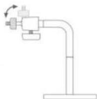
The Wireless Internet Camera comes with a camera stand (optional) with a swivel ball screw head that can be attached to the Wireless Internet Camera's bottom screw hole. Attach the camera stand to the Wireless Internet Camera and station it for your application. There are three holes located in the base of the camera stand allowing the Wireless Internet Camera to be mounted on the ceiling or any wall securely.

HARDWARE INSTALLATION
This section describes the Hardware installation procedure for the Wireless Internet Camera.
1 Attach Wireless Antenna
From the rear panel of the Wireless Internet Camera screw the 2 external Antenna that came with the Wireless Internet Camera into the antenna connector.

2 Configure Network Communication
From the rear panel of the Wireless
Internet Camera select the desired
Network communication for the
Wireless Internet Camera from the
Slide Switch. Position the Slide Switch
to the setting required either LAN or
LAN/WLAN position.
Please refer to the Physical Description.
section for detailed information.
3 Connect an Ethernet cable
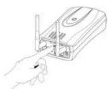
Connect an Ethernet cable to the
network cable connector located
on the Wireless Internet Camera's rear
panel and attach it to the network.

4 Attach the external power supply
Attach the external power supply to the DC power input connector located on Wireless Internet Camera's rear panel and is labeled DC 5V and connect it to your local power supply.
Note:
Confirm power source is supplied from the LED indicators label Power on the Wireless Internet Camera is illuminated.

natural_image
Hand inserting a USB into a device (no text or symbols visible)
SECURITY
To ensure the highest security and prevent unauthorized usage of the Wireless Internet Camera the Administrator has the exclusive privilege to access the System Administration for settings and control requirements to allow users the level of entry and authorize the privileges for all users. The Wireless Internet Camera supports multi-level password protection and access to the Wireless Internet Camera is strictly restricted to defined users whom has a "User Name" and "User Password" which is assigned by the Administrator.
Administrator can release a public user name and password so when remote users access the Wireless Internet Camera they will have the right to view the image transmitted by the Wireless Internet Camera.
Note:
When the Wireless Internet Camera is used for the first time it is highly recommended the Administrator sets the "Admin ID" and "Admin Password" to constrain users access to the Wireless Internet Camera since the Default settings are Null String. Once the ID and Password are defined only the Administrator has the access to management the Wireless Internet Camera. This
procedure should be done as soon as possible since the security features with the Wireless Internet Camera will not be enabled until the "Admin ID" and "Admin Password" is defined.

SOFTWARE INSTALLATION
This section describes the Software installation procedure of the Wireless Internet Camera for Web Configuration and IPView application.
Web Configuration
The Wireless Internet Camera must be configured through its built-in Web-based Configuration.
Extensive knowledge of LAN will be helpful in setting up the Wireless Internet Camera
From the web browser enter the default IP address to access the Welcome screen of the Wireless Internet Camera to configure your Wireless Internet Camera type http://192.168.0.20 in the address box. The number is the default IP address of your Wireless Internet Camera. Press Enter.

Note:
The PC's IP address must correspond with the Wireless Internet Camera's IP address in the same segment for the two devices to communicate.
Main Menu Image
After the default IP address is entered from the browser the Wireless Internet Camera Welcome screen will appear with a still image. There will be three options to choose from to set-up and view your Wireless Internet Camera and they are as follows:
View Image - ActiveX Mode
View Image - Java Mode
System Administration
![Welcome to the Internet Camera • Live Image - October Drive • Live Image - June Drive • Options And Connected [IMAGE]](/content/2026/05/925210/images/300859640d351919a69e2faa4864b211ed55637338a1795235d618d3c4217eb7.jpg)
System Administration
Click on "System Administration" from the Welcome screen to access the settings required for the Wireless Internet Camera.
There will be several options in the System menu bar to choose from to set your Wireless Internet Camera and they are as follows:
System
Image
Users
DateTime
Trigger
Information
Tools
System Administration
System Administration – System
The System menu contains commands for settings that are required for inputting key details to set-up the Wireless Internet Camera for operation.
Click on "System" in the system administration menu bar and the System screen will appear as illustrated below:
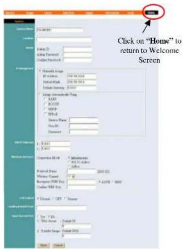
Camera Name:
This field is used for entering a descriptive name for the device.
The default setting for the Camera Name is CS-xxxxxx, where xxxxxx is the last six digit of the MAC Address. The maximum length is 32 (Printable ASCII).
Location:
This field is used for entering a descriptive name for the location used by the Wireless Internet Camera.
Admin:
This field is used for entering the Administrator ID along with the password to access the System Administration settings. Be sure to enter the password twice to confirm the details once in the Admin Password field and again in the Confirm Password field.
The default setting for Admin is blank space (Null String) you need to key in the Admin ID with a maximum length of 12 (Printable ASCII) characters and enter the Admin Password with a maximum length of 8 (Printable ASCII) characters.
It is highly recommended to set the Admin ID and Admin Password as soon as possible to enable security option for the Wireless Internet Camera to function.
IP Assignment:
Important Information
Access to the Wireless Internet Camera is done through assigning a proper IP address. Please make sure to use a vacant IP address when you assign the IP address for the Wireless Internet Camera. This will prevent errors from occurring if the IP address is overlapped.
There are two options to select from the IP Assignment either
Manually Assign or Assign Automatically Using.
Manually Assign
You can click "Manually Assign" and directly enter the IP address.
The default settings are as follows:
?? Default IP - 192.168.0.20
?? Subnet Mask - 255.255.255.0
?? Default Gateway - 0.0.0.0
Assign Automatically Using
If your network is using RARP, BOOTP or DHCP server you can click "Assign Automatically Using" and click on "RARP", "BOOTP" or "DHCP". Under this setting the Wireless Internet Camera will automatically assign an IP address from RARP, BOOTP or DHCP server. Each time the Wireless Internet Camera starts up be sure the RARP, BOOTP or DHCP server is setup as assign a static IP to your Wireless Internet Camera.
If your application requires direct connection from an ADSL modem through the Wireless Internet Camera's RJ-45 LAN port and you also have an ISP PPPoE account. Click on "PPPoE" option and enter the Service Name, User ID and Password into the respective fields.
The Wireless Internet Camera will get an IP address from the ISP each time the Wireless Internet Camera starts up.
DNS IP Address:
DNS (Domain Name System) server is an Internet service that translates domain names into IP addresses. Enter at least one DNS IP Address.
Wireless Interface:
Connection Mode:
Use the Connection Mode to determine the type of wireless communication for the Wireless Internet Camera. There are three choices of Infrastructure mode, 802.11 Adhoc mode and
Adhoc mode. The default setting for the Connection Mode is Infrastructure.
Note:
Keep in mind after setting the Wireless Interface make sure to check the Slide Switch on the rear panel is positioned to either LAN/WLAN or WLAN setting for the wireless communication to take effect.
Network Name:
This field is used to setup which wireless network (ESS-ID Extended Service Set ID) the Wireless Internet Camera is to be connected for communication. The ESS-ID is a unique identifier shared among all points in a wireless network environment.
The default Network Name is blank space (NULL String), this default setting will let the Wireless Internet Camera connect to ANY access point under the infrastructure network mode.
To connect the Wireless Internet Camera to a specific access point on the network make sure to set the ESS-ID of the Wireless Internet Camera to correspond with the access point's ESS-ID for communication. Type any string up to 32 characters long (spaces, symbols, and punctuation are not allowed) in the Network Name box.
To connect the Wireless Internet Camera to an Ad-hoc wireless workgroup make sure to set the same wireless channel and ESS-ID to match with the PC/Notebook wireless channel and ESS-ID for direct wireless communication under the Ad-hoc wireless workgroup (ad-hoc and 802.11 ad-hoc modes).
Note :
The Wireless Internet Camera ad-hoc mode supports two modes (802.11 ad-hoc mode and proprietary ad-hoc mode). Which option of the ad-hoc mode required depends on the operation of your Wireless Internet Camera. It depends on which ad-hoc mode is supported by your wireless card driver on the PC/Notebook. Some driver supports both modes, however, some driver support only one of the modes. The names of each ad-hoc mode may not be consistent between each wireless card vendor therefore you may need to try each of the ad-hoc mode (802.11 mode and proprietary mode) and select the mode that can communicate with each other.
Wireless Channel:
The pull down menu provides the wireless channel for communication. A "channel" is a range of frequencies to be used in communication between the Wireless Internet Camera and Access Point in infrastructure mode or the Wireless Internet Camera and PC/Notebook in Ad-hoc mode. Select the appropriate channel from the list provided depending on the
regulatory region which the unit is sold. The default setting is at channel 11.
Encryption WEP Key:
Wireless network communications are easily intercepted. WEP (Wired Equivalent Privacy) is an encryption method specified by the IEEE 802.11b standard to make any intercepted communications extremely difficult to interpret by unauthorized parties.
To enable WEP Encryption, first decide which WEP key format will be applied. Click on ASCII or HEX check box to select input format as ASCII format or HEX format, and then input WEP key. To Confirm the WEP key you must enter the data once again in the Confirm WEP Key field.
ASCII input format:
ASCII format causes each character you type to be interpreted as an eight-bit value. All unaccented upper- and lower-case Western European characters that can be input through your keyboard's typing zone are valid. To setup 64-bit WEP key, input 5 ASCII characters, for example, '12345'. To setup 128-bit WEP key, input 13 ASCII characters, for example, '1234567890123'. These character counts result in bit counts of 40 and 104, respectively; the Wireless Internet Camera will automatically pad your input to a bit count of 64 or 128.
HEX input format:
Hex format causes each pair of characters you type to be interpreted as an eight-bit value in hexadecimal (base 16) notation. Only the digits 0 through 9 and the letters A through F (in upper or lower case) are valid. To setup 64-bit WEP key, input 10 HEX format, for example, '3132333435', this is the
same with ASCII input '12345'. To setup 128-bit WEP key, input 26 IEX format, for example, '31323334353637383930313233', this is the same with ASCII input '1234567890123'. These character counts result in bit counts of 40 and 104, respectively; the Wireless Internet Camera will automatically pad your input to a bit count of 64 or 128.
On the Confirm WEP Key field, input the same characters as the Encryption Code field.
Make sure the Encryption Code is the same with the access point's encryption code that the Wireless Internet Camera is to be connected under Infrastructure mode. Your PC/Notebook's encryption code also needs to be setup the same with the Wireless Internet Camera's encryption code under either Infrastructure mode or Ad-hoc mode.
The default setting for the Encryption Key is Disable therefore, to secure the wireless transmission be sure to Enable the Encryption Key by entering the relevant data.
Note:
Carefully input Encryption Code, any error setting will cause communication link to fail.
LED Control:
The LED control allows user to setup the LED illumination as desired. This feature provides the flexibility when surveillance activity is ON.
There are three options as follows:
Normal -
Power - Steady On of the LED indicator.
LAN/WLAN - Steady On of the LED indicator. When LAN/WLAN activity is present the LED indicator will flash steadily.
OFF
Power - LED indicator is off
LAN/WLAN - LED indicator is off
Dur
Power - Steady On of the LED indicator.
LAN/WLAN - Steady On of the LED indicator with random flashing.
The default setting for the LED control is at Normal. When you have configured the LED control the correct illumination will set in after 1 minute.
Note:
This function is built-in to the LED indicators to add extra capabilities. The three options allow the Administrator to configure and camouflage the illumination for the LED indicator to falsify the monitoring status. In Normal Mode the LED indicator functions as normally. Under Off Mode the LED indicators are both off however, it is still monitoring the activity. In Dummy Mode the LED indicators operate in monitoring condition but monitoring activity is off or on.
Loading ActiveX From:
This field is used to specify the location of Xplug Control (ActiveX) plug-in program. Enter the information as required in .ocx format, for example:
http://www.
Open Second Port:
The Web Server field allows settings to open a second port for the Wireless Internet Camera. This will permit users IP Sharing Gateways to support multiple Wireless Internet Cameras. By default Port 80 is always opened for the Wireless Internet Camera Web Server access. Select "Yes" and input the second port value.
For example: If you have 5 Internet Camera to be installed, each with an IP address from
192.168.0.101
192.168.0.102
192.168.0.103
192.168.0.104
192.168.0.105
You can open the second port for each Internet Camera from port 81 to Port 85 as illustrated below:
Internet Camera 1 - IP 192.168.0.101, second web port 81
Internet Camera 2 - IP 192.168.0.102, second web port 82
Internet Camera 3 - IP 192.168.0.103, second web port 83
Internet Camera 4 - IP 192.168.0.104, second web port 84
Internet Camera 5 - IP 192.168.0.105, second web port 85
You also need to setup your DSL gateway for Port Mapping.
Port 81 map to 192.168.0.101
Port 82 map to 192.168.0.102
Port 83 map to 192.168.0.103
Port 84 map to 192.168.0.104
Port 85 map to 192.168.0.105
The Transfer Image field allows settings to open a second port for the Wireless Internet Camera to transfer images. The default Port 8481 is open image transfer and you can define a second port similar to the above.
Save/Cancel:
After making sure all settings in the System are correct, click on the "Save" icon to store the settings for the Wireless Internet Camera. You can alternatively click on the "Cancel" icon to restore all settings to the values last saved to or retrieved from the Wireless Internet Camera.
System Administration - Image
Image menu in the system administration contains commands to provide the settings for the images captured by the Wireless Internet Camera.
Click on "Image" in the system administration menu bar and the Image screen will appear as illustrated below:

Video Resolution:
Select the desired video resolution format ranging from 160x112, 320x240 (default) or 640x480
Compression Rate:
Select the desired compression rate with five levels from very low to very high. Higher video compression rate will generate more compact file size with less video quality and vise-versa. The default setting is at Medium.
Frame Rate:
Select the frame rate desired with default setting at Auto for optimal frame rate.
Brightness Control:
Adjust the brightness level with default setting at 64.
Contrast Control:
Adjust the contrast level with default setting at 64.
Hue Control:
Adjust the hue level with default setting at 64.
Light Frequency:
Adjust the light frequency to suit your area of operation from the options either 50 Hz or 60 Hz (default).
Note:
50 Hz and 60 Hz variants are available to accommodate the different light frequency found in USA (60 Hz) and Europe (50 Hz) for the Wireless Internet Camera to ensure better image quality.
Save/Cancel:
After making sure all settings in the Image are correct, click on the "Save" icon to store the settings for the Wireless Internet Camera. You can alternatively click on the "Cancel" icon to restore all settings to the values last saved to or retrieved from the Wireless Internet Camera.
System Administration - Users
The User options menu contains commands to allow system administrator to assign legal users who are permitted to monitor the Wireless Internet Camera from the remote site.
Click on "Users" in the system administration menu bar and the Users screen will appear as illustrated below:

Click on "Home"
to return to
Welcome Screen
Add User:
User Name:
Enter the user name in this field.
A maximum of 64 users names are allowed, however each user name must be different. Each user name can be used as a group given the password for example, if the User Name is "Guest" and the User Password is "Guest" anyone can access the Wireless Internet Camera with these details used as a group of users under
the User Name Guest. The maximum length for the User Name is 12 (Printable ASCII).
User Password:
Enter the user's password assigned by the administrator. The maximum password length is 8 (Printable ASCII).
I/O Output Control:
Administrator has the authority to give permission for the privilege to control the I/O Output Control to user's by selecting "Yes" or "No" to activate the I/O Output control.
To add a new users name input the necessary information first and click on the "Add" icon.
Delete User:
Select the user you wish to delete from the pull down menu and click on the "delete" icon.
Important Information
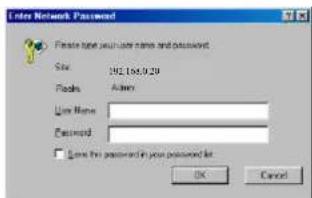
Once administrator has configured the Internet Camera Users, any user will be required to enter a login password to access the video image from the Wireless Internet Camera. The password dialog box is illustrated below.
System Administration – DateTime
The DateTime menu contains commands for setting the Wireless Internet Camera's time and date requirements to provide correct information to users who might be thousands of miles away in the remote site. There are two options to select from the DateTime menu bar either Synchronized with Time Server or Set Manually.
Click on "DateTime" in the system administration menu bar and the DateTime screen will appear as illustrated below:
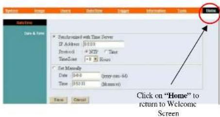
DateTime:
Select "Synchronized with Time Server" and the time will be based on GMT setting. The time will be synchronized every 10 minutes. This is also the default setting for the Wireless Internet Camera.
IP Address:
Enter the IP Address of the Time Server in this field.
Protocol:
Two options of NTP or Time are available for your selection to link with the Time Server. The default setting is NTP.
TimeZone:
System administrator must select the time zone for the region.
Please refer to the appendix for the time zone selection table.
To set the Date Time manually select "Set Manually" and system administrator must enter the Date and Time in the respective field manually.
Note:
When you select Set Manually, each time the Wireless Internet Camera is powered off and on you must re-enter the details once again due to time lost.
Save/Cancel:
After making sure all settings in the DateTime are correct, click on the "Save" icon to store the settings for the Wireless Internet Camera. You can alternatively click on the "Cancel" icon to restore all settings to the values last saved to or retrieved from the Wireless Internet Camera.
System Administration – Trigger
The Trigger menu contains commands for the I/O Trigger connectors providing the physical interface for 2 digital output and 2 digital input that is used for connecting a diversity of external alarm devices to the Wireless Internet Camera such as IR-Sensor and alarm relay.
Click on "Trigger" in the system administration menu bar and the Trigger screen will appear as illustrated below:

The default setting for the I/O Trigger functions are disabled you must enable the I/O Trigger first before the Triggers will perform.
There are two options to select from the Trigger screen I/O Input 1 Trigger and I/O Input 2 Trigger.
I/O Input 1 Trigger:
Select "Send e-mail attached with image" and enter the relevant information such as the SMTP Server Address, Sender e-mail Address, Receiver e-mail Address, Sending Interval and Sending Times.
?? SMTP (Simple Mail Transfer Protocol) is a protocol for sending e-mail messages between servers you need to input the mail server address in this field.
?? Sender e-mail is the person's e-mail address whom will be sending the e-mail.
?? Receiver e-mail is the e-mail address of the person whom will receive the e-mail.
?? Sending Interval is the period of time between each e-mail being sent to the receiver. If the setting is at 10 seconds, a new e-mail will be sent in 10 seconds interval to the receiver.
?? Sending Time is the number of times the e-mail will be sent to the receiver before it terminates.
Select “Trigger I/O Output” and enter the setting for the duration of the output device for Output 1 time and Output 2 time in seconds.
I/O Input 2 Trigger:
Select "Send e-mail attached with image" and enter the relevant information such as the SMPT Server Address, Sender e-mail Address, Receiver e-mail Address, Sending Interval and Sending Times.
?? SMTP (Simple Mail Transfer Protocol) is a protocol for sending e-mail messages between servers you need to input the mail server address in this field.
?? Sender e-mail is the person's e-mail address whom will be sending the e-mail.
?? Receiver e-mail is the e-mail address of the person whom will receive the e-mail.
?? Sending Interval is the period of time between each e-mail being sent to the receiver. If the setting is at 10 seconds, a new e-mail will be sent in 10 seconds interval to the receiver.
?? Sending Time is the number of times the e-mail will be sent to the receiver before it terminates.
Select “Trigger I/O Output” and enter the setting for the duration of the output device for Output 1 time and Output 2 time in seconds.
Save/Cancel:
After making sure all settings in the System are correct, click on the "Save" icon to store the settings for the Wireless Internet Camera. You can alternatively click on the "Cancel" icon to restore all settings to the values last saved to or retrieved from the Wireless Internet Camera.
Warning
When connecting other devices through the I/O connectors, please make sure the maximum current of 100mA is strictly observed. Any failure to do so might cause a loss of power to the Wireless Internet Camera and possibly cause serious damage to the Internet Camera.
Please refer to the appendix for detailed information regarding the I/O Connector.
System Administration - Information
The Information menu contains commands for displaying information about the Wireless Internet Camera.
Click on "Information" in the system administration menu bar and the Information screen will appear as illustrated below:
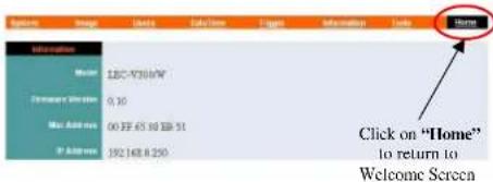
The Information table provides detailed information of the Wireless Internet Camera such as the Model Name, Firmware Version, Mac Address, and IP Address.
System Administration - Tools
The Tools menu contains commands for restarting the Wireless Internet Camera.
Click on "Tools" in the system administration menu bar and the Tools screen will appear as illustrated below:

Reset:
The Reset command restarts the Wireless Internet Camera just like turning the device off and on and saved settings are retained. The Reset panel contains the message "Do you really want to reset this device?" and a YES button. If you do not want to reset the Wireless Internet Camera, exit the panel without clicking YES, otherwise, click on the "YES" icon and the reset process will initiate.
Factory Reset:
A factory reset restarts the Wireless Internet Camera and returns all of its settings to their default values. The Factory Reset panel contains the message "Do you really want to factory reset this device?" and a YES button. If you do not want to carry out a factory reset command, exit the panel without clicking YES, otherwise click on the "YES" icon and factory reset will be initiated.
Note:
The Network must be reconfigured after a Factory Reset.
Once the configuration is completed click on "Home" to return to the Welcome screen and select the desired Viewing Image either through ActiveX Mode or Java Mode as described in the next section.
Then position the Wireless Internet Camera to the desired location appropriately for your purpose. Followed by adjustment of the Wireless Internet Camera focus, done manually by turning the lens clockwise or anti-clockwise to the desire image quality. Please refer to the appendix for detailed information regarding Adjust Internet Camera Focus and Replacing the Lens.
View Image – ActiveX Mode
To view video images from the browser, click on "View Image - ActiveX Mode" from the welcome screen to access the video images from Internet Explorer as illustrated below:
![View Image - ActiveX Maps DCF-100MW Ordnance Systems Inc. FM-TEST 2001-12-05 16:39:18 Camera Name# Location# ● Output 1 Trigger ON OFF ● Output 2 Trigger ON OFF [0-99] ● Click on "Home" return to Welcome Screen](/content/2026/05/925210/images/c913f7677911ffd959734d2768147c784b86aa166b7991faea30a57e7b1929fc.jpg)
Camera Name* - The Camera name will be displayed when the Camera Name field is entered in the Web Configuration setting under "System"
Location**- The location of the Wireless Internet Camera will be displayed when the Location field is entered in the Web Configuration settings under "System".
Note:
Please refer to the appendix on how to install ActiveX.
-
Install to the Web Server
-
Install to your Local PC
In the View Image – ActiveX Mode you are allowed two output trigger options. Just click on the desired selection "ON" or "OFF" to utilize the options for each of the output triggers (Output 1 trigger or Output 2 trigger).
Note 1:
Output trigger will send a 5V signal to the device connected to the Wireless Internet Camera. A maximum of two devices is permitted to connect to the Wireless Internet Camera to utilize the output trigger function. Please refer to appendix for detailed information.
Note 2:
Administrator has the authority to allow user's the permission to set the output trigger functions through the setting in the "Users" of System Administration menu bar.
View Image – Java Mode
Click on "View Image – Java Mode" from the Welcome screen to access the video images from the Internet Explorer or Netscape browser as illustrated below:

Camera Name* - The Camera name will be displayed when the Camera Name field is entered in the Web Configuration setting under "System"
Location** - The location of the Wireless Internet Camera will be displayed when the Location field is entered in the Web Configuration settings under "System".
In the View Image - Java Mode you are allowed two output triggers. Just click on the desired selection "ON" or "OFF" to utilize the options for each of the output triggers (Output 1 trigger or Output 2 trigger).
Note 1:
Output trigger will send a 5V signal to the device connected to the Wireless Internet Camera. A maximum of two devices is permitted to connect to the Wireless Internet Camera to utilize the output trigger function. Please refer to appendix for detailed information.
Note 2:
Administrator has the authority to allow user's the permission to set the output trigger functions through the setting in the "Users" of System Administration menu bar.

WIRELESS INTERNET CAMERA APPLICATION
The Wireless Internet Camera can be applied in wide variety of applications. It is an all-in-one device attached directly to an Ethernet or Fast Ethernet network and also supported by the wireless transmission based on the IEEE 802.11b standard. It is a standalone system with built-in CPU along with web-based solutions transmitting high quality video images for monitoring purposes. It can be managed remotely, accessed and controlled from any PC desktop over the Intranet or Internet via a web browser. With the easy installation procedure real-time live images will be available once the Wireless Internet Camera is installed coupled with the IPView application you can further expand the scope of the Wireless Internet Camera.
The following section will provide typical applications for the Wireless Internet Camera along with the IPView application and includes some basic knowledge to assist in the installation and configuration of the Wireless Internet Camera.
Applications
?? Monitoring of local and remote places and objects such as construction sites, hospitals, amusement parks, schools and day-care centers through the use of a web browser.
?? From the IPView application you can capture single frame images.
?? Connect up to two external devices to the Wireless Internet Camera for alarm notifications when a trigger is set off and you can configure to send-mail messages with a single frame image.
Internet Camera Application Diagrams

flowchart
graph TD
    A["HOME"] --> B["Study Room"]
    A --> C["Baby Room"]
    A --> D["Family Room"]
    A --> E["Kitchen"]
    A --> F["Back Yard"]
    B --> G["Phone Line"]
    C --> H["Phone Line"]
    D --> I["Phone Line"]
    E --> J["Phone Line"]
    F --> K["Phone Line"]
    style A fill:#f9f,stroke:#333
    style B fill:#ccf,stroke:#333
    style C fill:#ccf,stroke:#333
    style D fill:#ccf,stroke:#333
    style E fill:#ccf,stroke:#333
    style F fill:#ccf,stroke:#333
    style G fill:#fff,stroke:#000
    style H fill:#fff,stroke:#000
    style I fill:#fff,stroke:#000
    style J fill:#fff,stroke:#000
    style K fill:#fff,stroke:#000
    style_L["INTERNET"] --> M["AOM Cable Network"]
    M --> N["100m"]
    N --> O["Wireless Internet Cable"]
    O --> P["Back Yard"]
    Q["CCTV"] --> R["AOM Cable Network"]
    S["Back Yard"] --> T["Wireless Internet Cable"]
    U["Front Door"] --> V["Phone Line"]
    W["Phone Line"] --> X["Category 5 Cable"]
    Y["Phone Line"] --> Z["Coxial Cable"]
SOHO Applications
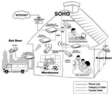
flowchart
graph TD
    subgraph SOHO
        A["SOHO"] --> B["Front Door"]
        B --> C["Warehouse"]
        C --> D["Wireless Internet Camera"]
        D --> E["Internet Control"]
        E --> F["Accessing Department"]
        F --> G["Mobile Phone"]
        G --> H["Data Department"]
        H --> I["Cloud Tower"]
        I --> J["Out Door"]
        J --> K["SOHO"]
    end

    subgraph Front Door
        L["SOHO"] --> M["Front Door"]
        M --> N["Data Department"]
        N --> O["Internet Control"]
        O --> P["Accessing Department"]
        P --> Q["Mobile Phone"]
        Q --> R["Data Department"]
        R --> S["Cloud Tower"]
        S --> T["Out Door"]
        T --> U["SOHO"]

    end

    subgraph Out Door
        V["SOHO"] --> W["Front Door"]
        W --> X["Data Department"]
        X --> Y["Internet Control"]
        Y --> Z["Accessing Department"]
        Z --> AA["Mobile Phone"]
        AA --> AB["Data Department"]
        AB --> AC["Cloud Tower"]
        AC --> AD["Out Door"]
        AD --> AE["SOHO"]

    style SOHO fill:#f9f,stroke:#333
    style Front Door fill:#ccf,stroke:#333
    style Out Door fill:#cfc,stroke:#333
Enterprise Applications
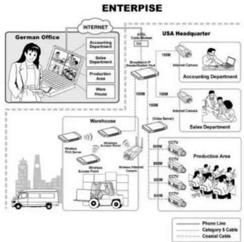
flowchart
graph TD
    A["German Office"] --> B["Accounting Department"]
    A --> C["Sales Department"]
    A --> D["Production Area"]
    A --> E["Ware House"]
    F["USA Headquarter"] --> G["Accounting Department"]
    F --> H["Sales Department"]
    F --> I["Production Area"]
    F --> J["Warehouse"]
    F --> K["Production Area"]
    L["Vehicle Bus"] --> M["Wireless Port Server"]
    M --> N["Wireless Access Point"]
    N --> O["Wireless Internet Camera"]
    P["Internet"] --> Q["Accounting Department"]
    P --> R["Sales Department"]
    P --> S["Production Area"]
    T["Cloud Cable Hub"] --> U["100M"]
    V["Broadcasted IP Reader/Server Port"] --> W["100M"]
    X["Video Server"] --> Y["100M"]
    Z["CCTV 500M"] --> AA["CCTV 500M"]
    AB["CCTV 500M"] --> AC["CCTV 500M"]
    AD["CCTV 500M"] --> AE["CCTV 500M"]
    AF["CCTV 500M"] --> AG["CCTV 500M"]
    AH["CCTV 500M"] --> AI["CCTV 500M"]
    AJ["CCTV 500M"] --> AK["CCTV 500M"]
    AL["CCTV 500M"] --> AM["CCTV 500M"]
    AN["CCTV 500M"] --> AO["CCTV 500M"]
    AP["Phone Line"] --> AQ["Category 6 Cable"]
    AP --> AR["Coastal Cable"]
I/O Connector Application


AUTO-RUN INSTALLATION
Insert the CD-ROM into the CD-ROM drive to initiated the auto-run program once completed a menu screen will appear as follows:
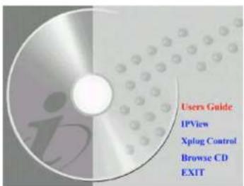
Then select the desired options from the menu buttons and they are as follows:
?? User's Guide
?? IPView
?? Xplug Control
?? Adobe Acrobat
?? Browse CD
?? Exit
To preview the User's Guide in .pdf format for detailed information regarding the installation procedure for the Wireless Internet Camera simply click on the "User's Guide" button.
To install the IPView application click on the "IPView" button to activate the installation procedure for the application program. Please refer to the next section for detailed information for installing IPView application.
To install Xplug Control (ActiveX) plug-in program into your PC/Notebook click on the "Xplug Control" button to activate the installation procedure for the plug-in program. Please refer to the appendix for detailed information regarding Installation of Xplug Control (ActiveX) into your PC/Notebook or Web Server.
If you do not have Adobe Acrobat Reader installed in your PC/Notebook click on the "Adobe Acrobat" button to activate the installation procedure. This will allow you to preview the User's Guide for the Wireless Internet Camera.
If you wish to glance the contents of the CD-ROM click on the "Browse CD" button and the content of the CD-ROM will be available for preview.
To exit the CD-ROM just double click on the "EXIT" button.
10
IPVIEW APPLICATION INSTALLATION
Installation
Insert the CD-ROM into the CD-ROM drive to initiate the autor-run program. Once completed a menu screen will appear as follows:

To install the IPView application click on the "IPView" button to activate the installation procedure for the application program.
Once executed a prompt will appear requesting the input of the desired language selection. Make the desired selection and click on "OK" to continue.

The Welcome screen will appear. Click on the "Next" button to proceed with the installation.

The License Agreement prompt will appear as below. Read the details carefully and click on the "Yes" icon to continue with the installation procedure.
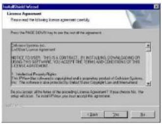
A prompt will appear and in the Destination Location dialog box, you may click on "Next" to accept the recommended destination location or click on "Browse" to select another location. After specifying the desired destination location, click on "Next" to proceed further.

The Select Program Folder prompt will appear providing information of where the IPView application will be located, click on "Next" to continue. If you wish to modify your settings, click on "Back" to return to the previous screens.

Please wait until one of the two dialog box to appear, select either "Yes. I want to restart my computer now" and click on the "Finish" icon to restart the computer to complete the installation procedure.
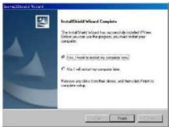
or click on the "Finish" icon to complete the installation procedure
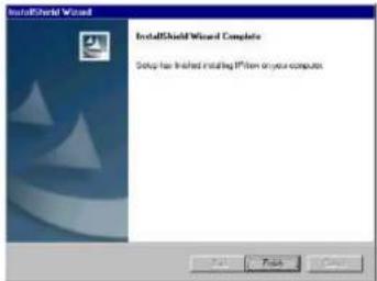
After successfully installing the IPView, the application program for the Wireless Internet Camera is automatically installed to \Programs\Files Directory.
To start running the IPView click on windows Start Menu/Programs/IPView/IPView

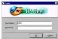
Once IPAddress is executed a Login prompt will appear, you must enter the default User Name: admin into the respective field and click on "OK" to log into the application.
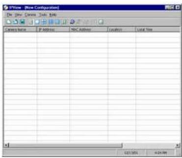
Once login, the IPView application is executed and IPView interface will appear as follows in the default List View format:
11
IPVIEW - GETTING STARTED
This section describes the operation of the IPView application User Interface with detailed procedures for using the application.
IPView
IPView is responsible for the management of preview, configuration, and searching of each camera.
It is designed with a user-friendly interface for case of control and navigation requirements as illustrated below.
![View [New Configuration] File Edit View Tools Help Current Name Of Additions MAC Additions Locations Local Time List view format](/content/2026/05/925210/images/8f1496bcebbd30a07240e44ff4d801ae153154a977df74f6fe9e4c0542b454f8.jpg)
How to Change Password
Change Password
When IPAddress is used for the first time it is highly recommended to change the User Name and Password by the Administrator to constrain users access to the IPAddress application. Once the User Name and Password are defined only the Administrator has access to the management of IPAddress applications. This procedure should be done as soon as possible to prevent unauthorized usage of IPAddress application.
Once IPAddress is executed a Login prompt will appear, you must enter the default Uscr Name: admin into the respective field and click on "OK" to log into the application.

To change the User Name and Password select "Tools" > "Options". The Options dialog box will appear as illustrated below.

The administrator needs to enter a User Name, Password and Confirm password into the respective fields. Once all the new details are entered click on the "OK" icon.
Make sure to save any changes you have made to keep the information updated.
Note: Alternatively you can click the Options icon as illustrated or use the hot key "F10".
How to Change IP Address
Change IP Address
To change an IP Address for a camera select "Camera" > "Add". An Add Camera dialog box will appear as illustrated below.
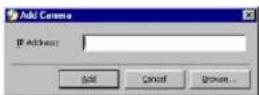
Click on the "Browse" icon, the Browse Camera dialog box will appear with a blank screen as illustrated below.

Click on the "Search" icon and IPView will detect and search all the available camera's that are installed on the local area network as depicted below:

You must highlight the camera you wish to change the IP Address and click on the "Change IP" icon and the Change IP Address dialog box will appear as depicted below:

Enter the new IP Address along with the Subnet Mask and Default gateway into the respective fields and click on the "OK" icon and IPView will automatically change the IP Address.
Make sure to save any changes you have made to keep the information updated.
How to Add a Camera
Add Camera
To add a new camera select "Camera" > "Add". An Add Camera dialog box will appear as illustrated below.

You can enter the IP Address of the camera in the specified field and click the "Add" icon to add a new camera. If the IP Address is entered incorrectly a dialog box will appear to notify the error.

If you are unsure of the IP Address of the camera you can click on the "Browse" icon, the Browse Camera dialog box will appear with a blank screen as illustrated below.

Click on the "Search" icon and IPView will detect and search all the available camera's that are installed on the local area network as depicted below:
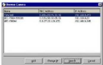
You must highlight the camera you wish to add and click on the "Add" icon. The Add Camera dialog box will appear once again with the IP Address entered. Click on the "Add" icon and the camera will be automatically added into IPSView list view format.
Alternatively you can double click on the camera you wish to add and the Add Camera dialog box will appear once again with the IP Address entered. Click on the "Add" icon and the camera will be automatically added into IPAddress list view format.

If the Login Camera dialog box appears make sure to enter the correct User Name and Password and click on the "OK" icon and the camera will be added into IPAddress in list format. If the User Name and Password is entered incorrectly the camera will not be added into IPAddress.
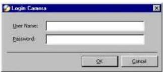
The above dialog box will appear only if administrator has already set the User Name and Password during the Web Configuration setting.
If you forget to highlight the camera you wish to add a dialog box will appear to notify you of the error.
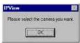
Make sure to save any changes you have made to keep the information updated.
Note 1: You are only able to add one camera at a time.
Note 2: Alternatively you can click the Add icon as illustrated or use the hot key "Shift+Ins".
How to Delete a Camera
Delete Camera
To delete a camera you must highlight the camera you wish to delete from IPSView list view format. From the menu bar select "Camera" > "Delete". A Delete Camera dialog box will appear and click on the "Yes" icon to delete the camera or click on "No" if you do not wish to delete the camera as illustrated below.

Make sure to save any changes you have made to keep the information updated.
Note:
Alternatively you can click the Delete icon as illustrated or use the hot key "Del".
How to View a Camera
View Camera
From the menu bar select "View" > "4 Cameras" (other choices are available in 1 Camera, 9 Cameras and 16 Cameras viewing format) and the viewing screen will appear with the video image.

natural_image
Four-panel photo collage showing a person at a desk, with one person partially visible in the background (no text or symbols)Note: The icon on the upper left corner of the screen will appear with the camera number that is being displayed
To return to the IPView list view format, click on the icon located on the upper left corner of the screen and a case sensitive menu
will appear. Select "List" and the viewing image will return to the list view format.
Note 1: A maximum of 16 cameras are available for viewing with the IPView application.
Note 2: Alternatively you can click the 1 Camera icon as illustrated or use the hot key "Ctrl+F3". For 4 Cameras, 9 Cameras and 16 Cameras click the respective icon or use the hot key as follows "Ctrl+F4", "Ctrl+F5" and "Ctrl+F6". To return to list view format use the hot key "Ctrl+F1".
How to Snap shot a Camera
Snap shot Camera
To snap shot a camera you must highlight the camera you wish to snap shot from the list view format. From the menu bar select "Camera" > "Snap shot". A Save Image dialog box will appear for you to save the snap shot picture.
A second alternative is from the viewing mode either 1, 4, 9, 16 cameras click on the icon located on the upper left corner of the
screen and a case sensitive menu will appear and select the "Snap shot" icon. A Save Image dialog box will appear for you to save the snap shot picture.
Note:
Alternatively you can click the Snap shot icon as illustrated or use the hot key "F5".
How to Adjust the Property Setting
Property Setting
"Property" is initiated by selecting "Camera" > "Property" and a dialog box will appear allowing settings of Web Configuration and upgrade firmware (Please refer to the appendix for detailed information). The Camera Property dialog box will appear for you to select the desired options from the tab selections to Configure the camera as shown below.
General
Allows settings for the camera name, location and administrator information such as administrator ID and password. Please refer
to the Web Configuration section under "System Administration - System" for further details.

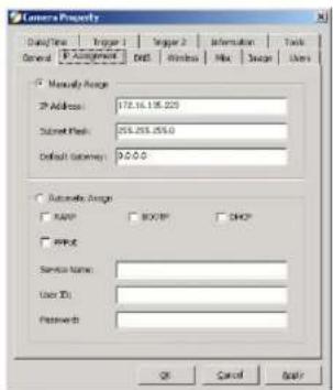
IP Assignment
There are two options to select from the IP Assignment either Manually Assign or Assign Automatically Using. Please refer
to the Web Configuration section under "System Administration - System" for further details.
DNS
DNS (Domain Name System) server is an Internet service that translates domain names into IP addresses. Enter at least one DNS IP Address. Please refer to the Web Configuration section under "System Administration – System" for further details.

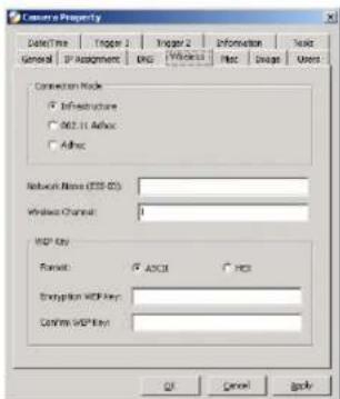
Wireless
(Please skip this section if your camera is not wireless)
Allows setting for connection mode, network name, wireless channel, and WEP key. Please refer to the Web Configuration section under "System Administration - System" for further details.
Misc
Allows setting for LED Control, ActiveX control location, and second port. Please refer to the Web Configuration section under "System Administration – System" for further details.

Image
Image provides the settings for the video image of the camera such as brightness, contrast, hue, resolution, compression, frame
rate, and light freq. Please refer to the Web Configuration section under "System Administration – Image" for further details.

Users
Contain commands to allow system administrator to assign legal users who are permitted to monitor the camera from the remote site by Add or Delete user.

To add a user click on the "Add" icon and the Add User dialog box will appear. Enter the User Name and Password into the specific field. Select the I/O Output Control to give users the privilege of accessing the I/O Output Control.
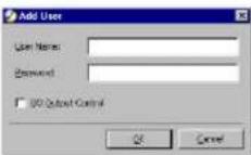
To delete a user, select the user and click on the "Delete" icon.
Please refer to the Web Configuration section under "System Administration – Users" for further details.
Date/Time
Contain commands for setting the camera's time and date to provide correct time information to users who might be thousands of miles away in the remote site by selecting Synchronized with Time Server or Set Manually. Please refer to the Web Configuration section under "System Administration - TimeDate" for further details.
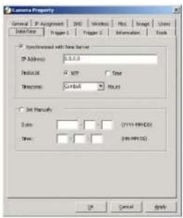
Trigger 1
Contains commands for setting the I/O Trigger connectors providing the physical interface for 1 digital output and 1 digital input that is used for connecting a diversity of external alarm devices to the camera such as IR-Sensor and alarm relay. Please refer to the Web Configuration section under "System Administration – Trigger" for further details.

Trigger 2
Contains commands for setting the I/O Trigger connectors providing the physical interface for 1 digital output and 1 digital input that is used for connecting a diversity of external alarm devices to the camera such as IR-Sensor and alarm relay. Please
refer to the Web Configuration section under "System Administration - Trigger" for further details.

Information
Displays information about the camera such as the model, firmware version, MAC address, and IP address. Please refer to
the Web Configuration section under "System Administration - Information" for further details.

Tools
Contains commands for reset the camera and update firmware (please refer to the appendix for detailed information). Please
refer to the Web Configuration section under "System Administration - Tools" for further details on reset.

Make sure to save any changes you have made to keep the information updated.
Note:
Alternatively you can click the Property icon as illustrated or use the hot key "F2".
Menu Bar
The menu bar provides easier access for users to navigate the IPView with different selections along with hot key capabilities as follows:
Menu Bar - File
"File" on the menu bar provides "New", "Open", "Save", "Save As" and "Exit" for users to create new files, open existing files, save files, and exit the IPView as depicted below.
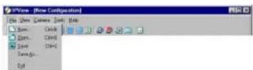
Menu Bar – View
“View” on the menu bar provide users with management capabilities for “Columns”, “List”, “Camera” and “Refresh”. You can view Camera in “1 Camera”, “4 Cameras”, “9 Cameras”, “16 Cameras”. The “View” menu bar is pictured below.

Columns
When "Columns" is launched a dialog box will appear allowing the option to choose the columns one would like to display in List View as illustrated below.

Viewing Format
You can view the format in "List" view. The "List" viewing format allows easy management and control of each camera.
List View
"List" view is illustrated below for your reference. You are able to list all the cameras and their properties such as the camera
name, IP address, user name, and location will be displayed for ease of control and management.

Note: Right click the mouse pad on any kind of the camera will bring up a context sensitive menu which shows the actions you can apply to the selected camera.
Double click on the desired camera will bring up the Property dialog box.
To update camera list view just click on the "Refresh" icon for Real Time Data and the latest information.
Menu Bar - Camera
“Camera” on the menu bar provides options to manage the camera. One can “Add” additional Camera with a maximum of 16 Camera allowed for viewing. Through the management function one can “Delete” a camera, manage the “Property”, “Enable” for real time and take a “Snap shot” image. The menu bar is illustrated below:
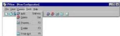
Enable Function
By default the video image is enabled. There will be a "check" next to the Enable command to show that the Enable function is working. To disable real-time image select "Camera" > "Enable" and real-time video image will stop and shutdown.
Menu Bar - Tools
"Tools" on the menu bar allows administrator management of the security settings such as User Name and Password to gain access into the IPView application. From the menu bar select "Tools" > "Options" and a dialog box will appear.
Administrator can change the User Name and Password for security settings to access the application.

Menu Bar - Help
"Help" on the menu bar provides "Contents" and "About" to instruct users how to operate the camera in HTLM format. From the menu bar select "Help" and can choose either "Contents" or "About" as depicted below:

IPView Icon Description

Open a new file. Alternatively the hot key is Ctrl+N.

Open an existing file. Alternatively the hot key is Ctrl+O.
Save a file. Alternatively the hot key is Ctrl+S.
List view format. Alternatively the hot key is Ctrl+F1.
1 Camera view format. Alternatively the hot key is Ctrl+F3.
4 Camera view format. Alternatively the hot key is Ctrl+F4.
9 Camera view format. Alternatively the hot key is Ctrl+F5.
16 Camera view format. Alternatively the hot key is Ctrl+F6.
Refresh IPView application. Alternatively the hot key is F12.
Add a camera. Alternatively the hot key is Shift+Ins.
Delete a camera. Alternatively the hot key is Del.
Property setting to configure the camera. Alternatively the hot key is F2.
Snap shot to capture a single still image. Alternatively the hot key is F5.
Options to modify the User Name and Password for IPView. Alternatively the hot key is F10.
Context Sensitive Menu
In list view format by highlighting a camera and right clicking the mouse pad will bring up a context sensitive menu for features such as "Add", "Delete", "Property", "Enable", and "Snap shot".

In view mode format click on the icon located on the upper left corner of the screen and a case sensitive menu will appear as illustrated below.

Features such as "Enable", "Snap shot", "List", "1 Camera", "4 Cameras", "9 Cameras", "16 Cameras", "Previous Page" and "Next Page" will be available.
12
UNINSTALL IPVIEW APPLICATION
Click on windows Start Menu / Settings / Control Panel. A prompt screen will be displayed like the one below and double click on the Add/Remove Programs icon.

106
From the Add/Remove Programs Properties Menu, select "IPView" as illustrated below.

Then click on the "Remove" button. A new prompt screen will be displayed like the one below confirming the removal.
Click on the "OK" icon to continue the process or click on the "Cancel" icon to reject the uninstall process.

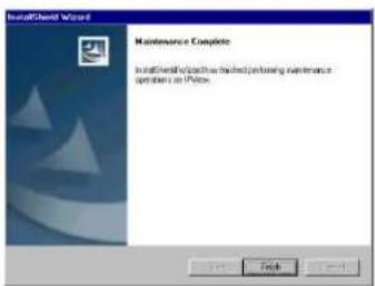
The InstallShield Wizard prompt will appear and click on "Finish" to complete the uninstallation procedure.
APPENDIX
A Frequently Asked Questions
Internet Camera Features
Q: What is an Internet Camera?
A: The Wireless Internet Camera is a standalone system connecting directly to an Ethernet or Fast Ethernet network and supported by the wireless transmission based on the IEEE 802.11b standard. It is different from the conventional PC Camera, the Wireless Internet Camera is an all-in-one system with built-in CPU and web-based solutions providing a low cost solution that can transmit high quality video images for monitoring. The Wireless Internet Camera can be managed remotely, accessed and controlled from any PC/Notebook over the Intranet or Internet via a web browser.
Q: What is the maximum number of users that can be allowed to access the Wireless Internet Camera simultaneously?
A: Maximum number of users that can log onto the Wireless Internet Camera at the same time is 64. Please keep in mind the overall performance of the transmission speed will slow down when many users are logged on.
Q: What algorithm is used to compress the digital image?
A: The Wireless Internet Camera utilizes the JPEG image compression technology providing high quality images for users. JPEG is adopted since it is a standard for image compression and can be applied to various web browser and application software without the need to install extra software.
Q: Can I change the wireless antenna attached to the Wireless Internet Camera?
A: The wireless antenna can be changed for a variety of reasons such as extending the wireless transmission range, however, please consult authorized distributors before attempting as the connectors must be SMA connector type.
Q: What is the wireless transmission range for the Wireless Internet Camera?
A: Generally the wireless distance can go up to 100 meters indoors and up to 300 meters outdoors. The range are limited by the number of walls, ceilings, or other objects that the wireless signals must pass through. Typical ranges vary depends on the types of materials and background Radio Frequency (RF) noise in your home or business and the configuration setting of your network environment.
Internet Camera Installation
Q: Can the Internet Camera be used out-doors?
A: The Wireless Internet Camera is not weatherproof. It needs to be equipped with a weatherproof case to be used outdoors and it is not recommended.
Q: What network cabling is required for the Wireless Internet Camera?
A: The Wireless Internet Camera uses Category 5 UTP cable allowing 10 Base-T and 100 Base-T networking.
Q: Can the Wireless Internet Camera be setup as a PC-cam on the computer?
A: No, the Wireless Internet Camera is an Internet Camera used only on Ethernet and Fast Ethernet network and supported by wireless transmission.
Q: Can the Wireless Internet Camera be connected on the network if it consists of only private IP addresses?
A: The Wireless Internet Camera can be connected to LAN with private IP addresses.
Q: Can the Wireless Internet Camera be installed and work if a firewall exists on the network?
A: If a firewall exists on the network, port 80 is open for ordinary data communication. However, since the Wireless Internet Camera transmits image data, the default port 8481 is also required. Therefore, it is necessary to open port 8481 of the network for remote users to access the Wireless Internet Camera.
B PING Your IP Address
The PING (Packet Internet Groper) command can determine whether a specific IP address is accessible by sending a packet to the specific address and waiting for a reply. It can also provide a very useful tool to confirm if the IP address conflicts with the Wireless Internet Camera over the network.
Follow the step-by-step procedure below to utilize the PING command but first you must disconnect the Wireless Internet Camera from the network.
Start a DOS window.
Type ping x.x.x.x, where x.x.x.x is the IP address of the Wireless Internet Camera.
The succeeding replies as illustrated below will provide useful explanation to the cause of the problem with the Wireless Internet Camera IP address.
C Trouble Shooting
Q: I cannot access the Wireless Internet Camera from a web browser?
A1: The possible cause might be the IP Address for the Wireless Internet Camera is already being used by another device. To correct the possible problem, you need to first disconnect the Wireless Internet Camera from the network. Then run the PING utility (follow the instructions in Appendix B - PING Your IP Address).
A2: Another possible reason is the IP Address is located on a different subnet. To fix the problem, run the PING utility (follow the instructions in Appendix B - PING Your IP Address). If the utility returns "no response" or similar, the finding is probably correct, then you should proceed as follows:-
In Windows 95/98/2000 and Windows NT, double check the IP Address of the Wireless Internet Camera is within the same subnet as your workstation.
Click "Start", "Setting", "Control Panel", and the "Network" icon.
Select TCP/IP from the "Network" dialog box and from the "TCP/IP Properties" dialog box click on "Specify an IP address". If the Wireless Internet Camera is situated on a different subnet than your workstation, you will not be able to set the IP address from this workstation. To verify make sure the first 3 sections of the IP address of the Wireless Internet Camera corresponds to the
first 3 sections of the workstation. Therefore the IP address of the Wireless Internet Camera must be set from a workstation on the same subnet.
A3: Other possible problems might be due to the network cable. Try replacing your network cable. Test the network interface of the product by connecting a local computer to the unit, utilizing a standard Crossover (hub to hub) Cable. If the problem is not solved the Wireless Internet Camera might be faulty.
Q: Why does the Power LED not light up constantly?
A: The power supply used might be at fault. Confirm that you are using the provided power supply DC 5V for the Wireless Internet Camera and verify that the power supply is well connected.
Q: Why does the LAN/WLAN LED not light up properly?
A1: There might be a problem with the network cable. To confirm that the cables are working, PING the address of a know device on the network. If the cabling is OK and your network is reachable, you should receive a reply similar to the following (...bytes = 32 time = 2 ms).
A2: The network device utilized by the Wireless Internet Camera is not functioning properly such as hubs or switches. Confirm the power for the devices are well connected and functioning.
A3: The wireless connection might be at fault. In ad-hoc mode make sure the Wireless Internet Camera wireless channel and ESS-ID is set to match the PC/Notebook wireless channel and ESS-ID for direct communication. Since The Wireless Internet Camera ad-hoc mode supports two modes (802.11 ad-hoc mode and proprietary ad-hoc mode). Which option of the ad-hoc mode
required depends on the operation of your Wireless Internet Camera. It depends on which ad-hoc mode is supported by your wireless card driver on the PC/Notebook. Some driver supports both modes, however, some driver support only one of the modes. The names of each ad-hoc mode may not be consistent between each wireless card vendor therefore you may need to try each of the ad-hoc mode (802.11 mode and proprietary mode) and select the mode that can communicate with each other.
Under infrastructure mode make sure the ESS-ID on the PC/Notebook and the Wireless Internet Camera must match with the Access Point's ESS-ID.
Q: Why does the Wireless Internet Camera work locally but not externally?
A1: Might be caused from the firewall protection. Need to check the Internet firewall with your system administrator.
A2: The default router setting might be a possible reason. Need to double check if the configuration of the default router settings is required.
Q: Why does a series of broad vertical white line appears through out the image?
A: A likely issue is that the CMOS sensor becomes overloaded when the light source is too bright such as direct exposure to sunlight or halogen light. You need to reposition the Wireless Internet Camera into a more shaded area immediately as this will damage the CMOS sensor.
Q: There is bad focus on the Wireless Internet Camera, what should be done?
A1: The focus might not be correctly adjusted for the line of sight. You need to adjust the Wireless Internet Camera focus manually as described in Adjust Internet Camera Focus.
A2: There is no adaptor fitted with your C-type lens. If you have previously changed the supplied CS-type lens, you may have unintentionally installed a C-type lens without fitting the adaptor first.
Q: Noisy images occur how can I solve the problem?
A1: The video images might be noisy if the Wireless Internet Camera is used is a very low light environment. To solve this issue you need more lighting.
A2: There might be wireless transmission interference make sure there are no other wireless devices on the network that will affect the wireless transmission.
Q: There is poor image quality, how can I improve the image?
A1: A probable cause might be the incorrect display properties configuration for your desktop. You need to open the Display Properties on your desktop and configure your display to show at least 65'000 colors for example at least 16-bit.
Note:
Applying only 16 or 256 colors on your computer will produce dithering artifacts in the image.
A2: The configuration on the Wireless Internet Camera image display is incorrect. Through the Web Configuration Image
section you need to adjust the image related parameter for improve images such as brightness, contrast, hue and light frequency. Please refer to the Web Configuration section for detail information.
Q: There are no images available through the web browser?
A: The ActiveX might be disabled. If you are viewing the images from Internet Explorer make sure ActiveX has been enabled in the Internet Options menu. Alternatively, you can use the Java Applet for viewing the required images.
D I/O Connector
I/O Connector Definition for Wireless Internet Camera
An 8-pole connector is provided for auxiliary IO connections to the Wireless Internet Camera.
The IO connector provides the physical interface for 2 digital output and 2 digital input that is used for connecting a diversity of external alarm devices to the Wireless Internet Camera such as IR-Sensor and alarm relay.
The digital input is used for connecting external alarm devices and once triggered images will be taken and e-mailed.
The supported transistor output can give a maximum of DC 5V to the externally connected alarm devices and once triggered the current will activate the devices.
| In 11 In 12 | In 11 & In 12 is a pair for digital input. It works at voltage 5V |
| In 21 In 22 | In 21 & In 22 is a pair for digital input. It works at voltage 5V |
| Out 1 + Out 1 - | Out 1 - & Out 1 + is a pair for digital out. The out put voltage is 5 V and maximum current is 100 mA |
| Out 2 + Out 2 - | Out 2 - & Out 2 + is a pair for digital out. The out put voltage is 5 V and maximum current is 100 mA |
I/O Schematic Diagram

flowchart
graph TD
    A["5V"] --> B["In1"]
    B --> C["DoorSwitch1"]
    D["IN1"] --> E["SSR"]
    E --> F["In2"]
    F --> G["In21"]
    G --> H["DoorSwitch2"]
    I["IN2"] --> J["SSR"]
    J --> K["In22"]
    K --> L["Out1+"]
    M["OUTPUT 1"] --> N["SSR"]
    N --> O["Out1-"]
    P["OUTPUT 2"] --> Q["SSR"]
    Q --> R["Out2+"]
    S["OUT 2"] --> T["SSR"]
    T --> U["Out2-"]
    V["External Power"] --> W["Relay"]
    W --> X["9"]
    Y["5V"] --> Z["In1"]
    Z --> AA["In2"]
Warning
- When connecting a device to the Input connector, the device must be a passive component without voltage and electrical current.
- When connecting other devices through the Output connector, please make sure the maximum current of DC 5V, 100mA is strictly observed.
- Any failure of the above two points might cause serious damage to the camera.
Note:
Through the Web Configuration in the Trigger section, you must first enable the trigger function. Please refer to the Web Configuration section for detailed information.
E Upgrade Firmware
User's can update firmware from the IPView application. Select "Camera" > "Properties" and the Camera Property dialog box will appear. Select the Tools tab and enter the full path of the firmware binary file name in the Update Firmware field or you can click on the "Browse" icon to select the file. Once the firmware file is entered click on the "Update" icon to proceed with the updating process. Once completed click on the "OK" icon as illustrated below

Warning
During firmware update process please make sure no interruptions will occur as it might possibly cause serious damage to the Internet Camera
F Time Zone Table
[GMT-12-00] Enwetok Kwazlein
(GMT-11.00) Midway Island, Samoa
[GMT-10:00]Hawaii
[GMT-09:00] Alaska
IGMT-08.00) Pacific Time (US & Canada) Tijuana
IGMT-07:00|Arizona
(IGMT-07.00) Mountain Time (US & Canada)
(GMT-06.00) Central Time (US & Canada)
IGMT-06:00 Mexico City, Tequipalba
(IGMT-06.00) Saskatchewan
IGMT-05:00! Bogota Lima
(IGMT-05.00) Eastern Time (US & Canada)
IGMT-05:00 Indiana (East)
(GMT-04.00) Atlantic Time (Canada)
(IGMT-04.00) Cavaas La Paz
(d.m.) 04.00, Calabas, El Pal
(GMT-04:00) Santiago
[GMT-03:30] Newfoundland
[GMT-03:00] Brasília
(GMT-03:00) Buenos Aires, Georgetown
IGMT-02 001 Mid-Atlantic
IGMT-01-001 Azores, Cape Verde Is
(IGMT)Casablanca Montovia
[GMT] Greenwich Mean Time: Dublin, Edinburgh, Lisbon, London
(GMT+01:00) Amsterdam, Berlin, Bern, Rome, Stockholm, Vienna
(IGMT+01:00) Belgrade, Bratislava, Budapest, Liubljana, Prague
(GMT+01:00) Brussels, Copenhagen, Madrid, Paris, Vilnius
[GMT+01:00] Sarajevo, Skopje, Sofija, Warsaw, Zagreb
(GMT+02:00) Athens, Istanbul, Minsk.
(GMT+02:00) Bucharest
(GMT+02:00) Cairo
(GMT+02:00) Harare, Pretoria
(GMT+02:00) Helsinki, Riga, Tallinn
[GMT+02:00] Jerusalem
(GMT+03:00) Baghdad, Kuwait, Riyadh
[GMT+03:00] Moscow, St. Petersburg, Volgograd
(GMT+03.00) Nairobi
(GMT+03:30) Tehran
(GMT+04:00) Abu Dhabi, Muscat
(GMT+04:00) Baku, Tbăni
IGMT+04:301Kabul
(GMT+05:00) Ekaterinburg
(IGMT+05:00) Islamabad, Karachi, Tashkent
IGMT+05:301 Bombay, Calcutta, Madras, New Delhi
(GMT+06:00) Astana, Almahu, Dhaka
(GMT+06:00) Colombo
[Unreadable]
IGMT+07:001 Bangkok, Hanoi, Jakarta
(GMT+08:00) Beijing, Chongqing, Hong Kong, Urumqi
(GMT+08:00) Perth
(GMT-08:00) Singapore
(GMT+08.00) Singapore
(GMT+08:00) Taipei
(GMT+09:00) Osaka, Sapporo, Tokyo
(GMT+09:00) Seoul
(GMT+09:00) Yakutsk
(IGMT+09 30) Adelaide
(GMT+09:30) Davian
(GMT+10:00) Brisbane
(CMT-10.00) Brisbane
[GMT+10:00] Canberra, Melbourne, Sydney
(GMT+10:00) Guam, Port Moresby
(GMT+10:00) Hobart
(IGMT+10:00) Vladyslostok
[2017] 4.2022 [中国证券报]
[GMT+08:00] Singapore
(GMT+08:00)Taine
JGMT+09:001Osaka Sapporo Toku
(GMT:09:00) Seoul
(GMT+05.00) Seba
[GMT+09:00] Yakuisk
(GMT+09:30) Adelaide
(GMT+09:30) Darwin
(GMT+10:00) Bosban
(GMT+10.00) Caribana, Melbourne, Sydney
(GMT+10.00) Canberra, Melbourne, Sydney (GMT-10.00)
(GMT+10:00) Guam, Port Moresby
[GMT+10:00] Hobai
(GMT+10:00) Vladvostok
(GMT+11:00) Mapadan, Solomon Is. New Caledonia
(GMT+12:00) Auckland, Wellington
(GMT+12.00) Auckland, Wellington (GMT+12.00) Fri Kanobello Markhalle
G Xplug Control Installation
Installation To Web Server
Important Information
It is highly recommended to install the Xplug Control application to the Web Server for 1E 5.0. It must be installed to a Public Domain with Fixed IP address.
1. Installation:
Copy the "xplug.ocx" file to any WEB Server table.
2. Setting (Configuration):
From the Web Configuration menu select "System" and under the "Loading ActiveX From" input web server location (http://www.web server location.com/).
Once the settings are completed the user now is able to access the Internet Camera from the web browser by selecting the image view – ActiveX mode.
Installation To Local PC
Insert the CD-ROM into the CD-ROM drive to initiated the auto-run program once completed a menu screen will appear as follows:

To install Xplug Control click on the "Xplug Control" button to activate the installation procedure for the plug-in program.
Once executed a prompt will appear requesting the input of the desired language selection. Make the desired selection and click on "OK" to continue.

The Welcome screen will appear. Click on the "Next" button to proceed with the installation.

The License Agreement prompt will appear as below. Read the details carefully and click on the "Yes" icon to continue with the installation procedure.

Click on the "Finish" button to complete Setup of the Xplug Control Utility program for the Wireless Internet Camera.

H Adjust Internet Camera Focus
The Wireless Internet Camera features an exchangeable CS-type lens that can be used for different applications as necessary. It supports rotational focus control so the lens can be adjusted to focus under normal and stable conditions to maximize the image quality of the Wireless Internet Camera.
To adjust the focus of the lens you need to turn the lens slowly in either clockwise or anti-clockwise direction until the desired image appears. DO NOT over turn the lens in either of the directions as it will be out of focus. Unless you want to substitute the lens DO NOT unscrew more than 1.0mm apart from the Fixed Lens Assembly.
Keep in mind while adjusting the Wireless Internet Camera's focus you can review the image quality from the Web browser.
Camera Lens
Adjust by turning
clockwise or anti-clockwise

Note: You can further adjust the Wireless Internet Camera's image quality through the Web Configuration under System Administration - Image. Please refer to Web Configuration section for further details.
Warning
Direct exposure to sunlight may cause permanent damage to the CMOS sensor. Therefore do not expose the Internet Camera's lens directly to sunlight. When operation is required in glaring light environment, it is recommended to use an iris lens.
The Internet Camera is designed for indoor usage and if your application requires prolong exposure to sunlight, a sun visor is recommended to protect the Internet Camera.
Replacing the Lens
Since the Wireless Internet Camera is designed with a CS- mount, the lens equipped with the Wireless Internet Camera can be replaced with any standard C or CS lens commonly used within the surveillance industry.
Follow the instructions below to replace the supplied lens with any C or CS type lens.
- Unscrew the Wireless Internet Camera lens
-
C-lens only, attach the new lens to a CS-C adapter
-
Screw the new lens onto the Wireless Internet Camera. If appropriate, adjust the iris according to the prevailing light conditions.
- Refer to Adjusting the Wireless Internet Camera Focus on the previous page.
- Refresh the web browser and monitor the results from the Wireless Internet Camera.

I Specification
Video specification
| Resolution: | 640 x 480 pixel |
| Sensor: | 1/3" color CMOS sensor |
| Gain control: Automatic | |
| Exposure: Automatic | |
| White Balance: Automatic | |
| Shutter: | Electronics 1/60 ~ 1/15000 sec |
| Minimum Illumination: | 2.5lux@F1.4, 3000K color |
| Focal Length: 6.0 mm | |
| Aperture: f=1.8 | |
| Focus Extent: | 20 cm - 8 |
| Lens mounting: | Fixed board lens, CS-mount type |
Image (Video Setting)
| Image compression: | JPEG |
| Frame rate: | 30fps@QSIF, 20fps@QSIF, 3fps@VGA |
| Compression Rate selection: | 5 level (Very Low, Low, Medium, High, Very High) |
| Frame rate setting: | 1, 5, 7, 15, 20, auto (depends on the video format) |
| Video resolution: | 160x120, 320x240, 640x480 |
| Brightness control: | Range 1- 128 |
| Contrast control: | Range 1- 128 |
| Hue control: | Range 1- 128 |
System Hardware
| LAN Connector: | One RJ-45 port to connect to 10/100Mbps Ethernet, auto-sensed | |
| Wireless LAN: | Built-in 802.11b wireless LAN module (Wi-Fi compliant) | |
| Generic I/O Port: | Four I/O ports, two for input and two for outputTotal 8-pin: | |
| Pin 1 | Input Port (1) | |
| Pin 2 | Input Port (1) | |
| Pin 3 | Input Port (2) | |
| Pin 4 | Input Port (2) | |
| Pin 5 | Output Port (1+) | |
| Pin 6 | Output Port (1-) | |
| Pin 7 | Output Port (2+) | |
| Pin 8 | Output Port (2-) | |
Note:
The output voltage is DC 5V and maximum current is 100mA.
| LED Indicator: | Power LED (Blue) |
| LAN/WLAN Activity LED (Orange) |
Note:
| LED three mode setting can be changed by software. (Normal / Off / Dummy) | |
| Power Supply: DC 5V/2.4A, switching type | |
| Power Communication: 6.5 Watt (1300mA x 5V) | |
| Slide Switch: LAN/LAN&WLAN/WLAN | |
| Antenna Connector: 2 connectors |
Communication Support
Communication: There will be three modes available,
selected by slide switch on the rear panel
10/100Mbps Ethernet only
10/100Mbps Ethernet and
802.11b wireless LAN.
802.11b wireless LAN only
Encryption: 64 bit, 128 bit or OFF
Communication protocol: HTTP, FTP, TCP/IP, UDP, ARP,
ICMP, BOOTP, RARP, DHCP, PPPoE
Browser Support
System requirement:
CPU: Pentium II, 266 MHz or above
Memory Size: 32 MB (64 MB recommended)
VGA card resolution: 800x600 or above
?? Internet Explorer 5.0 or above (ActiveX & JAVA Mode - View Image for windows OS and JAVA Mode - View Image for other OS)
?? Netscape 6.0 or above (JAVA Mode - View Image)
IPView Application
Support OS: Win 98, Win 98 SE, Win 2000, Win Me, Win XP
System requirement for IPView:
CPU: Pentium III, 450 MHz or above
Memory Size: 128 MB (256 MB recommended)
VGA card resolution: 800x600 or above
Operating environment
Operating temperature: 5?C \~ 50?C
Storage temperature: -25?C - 50?C Humidity: 5% \~ 95% non-condensing
EMI FCC, CE, VCCI
G Glossary of Terms
NUMBERS
| 10BASE-T | 10BASE-T is Ethernet over UTP Category III,IV, or V unshielded twisted-pair media. |
| 100BASE-TX | The two-pair twisted-media implementation of 100BASE-T is called 100BASE-TX. |
| 802.11b | An IEEE standard for wireless local area networks. It offers transmissions speeds at up to 11 Mbps in the 2.4-GHz band. |
A
| Access point | It is the hardwa re interface between a wireless LAN and a wired LAN. The access point attaches to the wired LAN through an Ethernet connection. |
| Applet | Applets are small Java programs that can be embedded in an HTML page. The rule at the moment is that an applet can only make an Internet connection to the computer form which the applet was sent. |
| ASCII | American Standard Code For Information Interchange, it is the standard method for encoding characters as 8bit sequences of binary numbers, allowing a maximum of 256 characters. |
| ARP | Address Resolution Protocol. ARP is a protocol that resides at the TCP/IP Internet layer which delivers data on the same network by |
translating an IP address to a physical address.
AVI Audio Video Interleave, it is a Windows platfo rm audio and video file type, a common format for small movies and videos.
B
BOOTP Bootstrap Protocol is an Internet protocol that can automatically configure a network device in a diskless workstation to give its own IP address.
C
Communication Communication has four components: sender, receiver, message, and medium. In networks, devices and application tasks and processes communicate messages to each other over media. They represent the sender and receivers. The data they send is the message. The cabling or transmission method they use is the medium.
Connection In networking, two devices establish a connection to communicate with each other.
D
DHCP Dynamic Host Configuration Protocol was developed by Microsoft a protocol for assigning dynamic IP addresses to devices on a network. With dynamic addressing, a device can have a different IP address every time it connects to the network. In some systems, the device's IP address can even change while it is still connected. DHCP also supports a mix of static and dynamic IP addresses. This simplifies the task for network administrators because the software keeps track of IP addresses rather than
requiring an administrator to manage the task. This means a new computer can be added to a network without the hassle of manually assigning it a unique IP address. DHCP allows the specification for the service provided by a router, gateway, or other network device that automatically assigns an IP address to any device that requests one
DNS Domain N name System is an Internet service that translates domain names into IP addresses. Since domain names are alphabetic, they're easier to remember. The Internet however, is really based on IP addresses every time you use a domain name the DNS will translate the name into the corresponding IP address. For example, the domain name www.network_camera.com might translate to 192.167.222.8.
E
Enterprise network An enterprise network consists of collections of networks connected to each other over a geographically dispersed area. The enterprise network serves the needs of a widely distributed company and operates the company's mission-critical applications.
Ethernet The most popular LAN communication technology. There are a variety of types of Ethernet, including 10 Mbps (traditional Ethernet), 100 Mbps (Fast Ethernet), and 1,000 Mbps (Gigabit Ethernet). Most Ethernet networks use Category 5 cabling to carry information, in the form of electrical signals, between devices. Ethernet is an implementation of CSMA/CD that operates in a bus or star topology.
F
Fast Ethernet Fast Ethernet, also called 100BASE-T, operates at 10 or 100Mbps
per second over UTP, STP, or fiber-optic media.
Firewall
Firewall is considered the first line of defense in protecting private information. For better security, data can be encrypted. A system designed to prevent unauthorized access to or from a private network. Firewalls are frequently used to prevent unauthorized Internet users from accessing private networks connected to the Internet, especially Intranets all messages entering or leaving the intranet pass through the firewall, which examines each message and blocks those that do not meet the specified security criteria.
G
Gateway
A gateway links computers that use different data formats together.
Group
Groups consist of several user machines that have similar characteristics such as being in the same department.
H
HEX
Short for hexadecimal refers to the base-16 number system, which consists of 16 unique symbols: the numbers 0 to 9 and the letters A to F. For example, the decimal number 15 is represented as F in the hexadecimal numbering system. The hexadecimal system is useful because it can represent every byte (8 bits) as two consecutive hexadecimal digits. It is easier for humans to read hexadecimal numbers than binary numbers.
I
IEEE
Institute of Electrical and Electronic Engineers.
Intranet This is a private network,
inside an organization or company, that
uses the same software you will find on the public Internet. The only difference is that an Intranet is used for internal usage only.
The Internet is a globally linked system of computers that are logically connected based on the Internet Protocol (IP). The Internet provides different ways to access private and public information worldwide.
To participate in Internet communications and on Internet Protocol-based networks, a node must have an Internet address that identifies it to the other nodes. All Internet addresses are IP addresses
Internet Protocol is the standard that describes the layout of the basic unit of information on the Internet (the packet) and also details the numerical addressing format used to route the information. Your Internet service provider controls the IP address of any device it connects to the Internet. The IP addresses in your network must conform to IP addressing rules. In smaller LANs, most people will allow the DHCP function of a router or gateway to assign the IP addresses on internal networks.
IP address is a 32-binary digit number that identifies each sender or receiver of information which is sent in packets across the Internet. For example 80.80.80.69 is an IP address, it is the closet thing the Internet has to telephone numbers. When you "call" that number, using any connection methods, you get connected to the computer that "owns" that IP address.
Provider, is a company that maintains a network
that is linked to the Internet by way of a dedicated communication line. An ISP offers the use of its dedicated communication lines to companies or individuals who can't afford the high monthly cost for a direct connection.
Internet
Internet address
IP
IP address
ISP Internet Service
J
JAVA
Java is a programming language that is specially designed for writing programs that can be safely downloaded to your computer through the Internet without the fear of viruses. It is an object-oriented multi-thread programming best for creating applets and applications for the Internet, Intranet and other complex, distributed network.
L
LAN
Local Area Network a computer network that spans a relatively small area sharing common resources. Most LANs are confined to a single building or group of buildings.
N
NAT
Network Address Translator generally applied by a router, that makes many different IP addresses on an internal network appear to the Internet as a single address. For routing messages properly within your network, each device requires a unique IP address. But the addresses may not be valid outside your network. NAT solves the problem. When devices within your network request information from the Internet, the requests are forwarded to the Internet under the router's IP address. NAT distributes the responses to the proper IP addresses within your network.
Network
A network consists of a collection of two or more devices, people, or components that communicate with each other over physical or virtual media. The most common types of network are:
LAN - (local area network): Computers are in close distance to one another. They are usually in the same office space, room, or building.
WAN - (wide area network): The computers are in different
geographic locations and are connected by telephone lines or radio waves.
NWay Protocol A network protocol that can automatically negotiate the highest possible transmission speed between two devices.
P
PING Packet Internet Groper, a utility used to deter mine whether a specific IP address is accessible. It functions by sending a packet to the specified address and waits for a reply. It is primarily used to troubleshoot Internet connections.
PPPoE Point-to-Point Protocol over Ethernet. PPPoE is a specification for connecting the users on an Ethernet to the Internet through a common broadband medium, such as DSL or cable modem. All the users over the Ethernet share a common connection.
Protocol Communication on the network is governed by sets of rules called protocols. Protocols provide the guidelines devices use to communicate with each other, and thus they have different functions. Some protocols are responsible for formatting and presenting and presenting data that will be transferred from file server memory to the file server's net work adapter. Others are responsible for filtering information between networks and forwarding data to its destination. Still other protocols dictate how data is transferred across the medium, and how servers respond to workstation requests and vice versa. Common network protocols responsible for the presentation and formatting of data for a network operating system are the Internetwork Packet Exchange (IPX) protocol or the Internet Protocol (IP). Protocols that dictate the format of data for transferors the medium include token-passing and Carrier Sense Multiple Access with Collision Detection (CSMA/CD), implemented as token-ring, ARCNET, FDDI, or Etheract. The Router Information Protocol (RIP), a part
of the Transmission Control Protocol/Internet Protocol (TCP/IP) suite, forwards packets from one network to another using the same network protocol.
R
RARP Reverse Address Resolution Protocol, a TCP/IP protocol that allows a physical address, such as an Ethernet address, to be translated into an IP address.
RJ-45 RJ-45 connector is used for Ethernet cable connections.
Router A router is the network software or hardware entity charged with routing packets between networks.
S
Server It is a simple computer that provides resources, such as files or other information.
SMTP The Simple Mail Transfer Protocol is used for Internet mail.
SNMP Simple Network Management Protocol. SNMP was designed to provide a common foundation for managing network devices.
Station In LANs, a station consists of a device that can communicate data on the network. In FDDI, a station includes both physical nodes and addressable logical devices. Workstations, single-attach stations, dual-attach stations, and concentrators are FDDI stations.
Subnet mask In TCP/IP, the bits used to create the subnet are called the subnet mask.
T
(TCP/IP) Transmission Control Protocol/Internet Protocol is a widely used transport protocol that connects diverse computers of various transmission methods. It was developed by the Department of Defense to connect different computer types and led to the development of the Internet.
Transceiver A transceiver joins two network segments together. Transceivers can also be used to join a segment that uses one medium to a segment that uses a different medium. On a 10BASE-5 network, the transceiver connects the network adapter or other network device to the medium. Transceivers also can be used on 10BASE-2 or 10BASE-T networks to attach devices with AUI ports.
U
UDP The User Datagram Protocol is a connectionless protocol that resides above IP in the TCP/IP suite
ULP The upper-layer protocol refers to Application Layer protocols such as FTP, SNMP, and SMTP.
User Name The USERNAME is the unique name assigned to each person who has access to the LAN.
Utility It is a program that performs a specific task.
UTP Unshielded twisted-pair. UTP is a form of cable used by all access methods. It consists of several pairs of wires enclosed in an unshielded sheath.
W
| WAN | Wide-Area Network. A wide-area network consists of groups of interconnected computers that are separated by a wide distance and communicate with each other via common carrier telecommunication techniques. |
| Windows | Windows is a graphical user interface for workstations that use DOS. |
| Workgroup | A workgroup is a group of users who are physically located together and connected to the same LAN, or a group of users who are scattered throughout an organization but are logically connected by work and are connected to the same network group. |
| Workstations | Workstation refers to the intelligent computer on the user's desktop. This computer may be an Intel-based PC, a Macintosh, or a UNIX-based workstation. The workstation is any intelligent device a user works from. |
- TABLE OF CONTENTS
- UNPACKING THE WIRELESS INTERNET CAMERA ...19
- HARDWARE INSTALLATION 21
- SECURITY 24
- SOFTWARE INSTALLATION....26
- WIRELESS INTERNET CAMERA APPLICATION ....56
- ABOUT THIS GUIDE
- INTRODUCTION
- SYSTEM REQUIREMENT
- Wireless Internet Camera
- Network:
- Recommended PC or Notebook to Access the Wireless Internet Camera
- IPView Application:
- FEATURES AND BENEFITS
- Simple To Use
- Support Variety of Platforms
- Wired and Wireless Network Support
- Web Configuration
- Remote Utility
- Connection to External Devices
- Broad Range of Applications
- 4
- PHYSICAL DESCRIPTION
- Front Panel
- Power LED
- Note:
- LAN/WLAN LED
- Rear Panel
- Network Cable Connector
- DC Power Connector
- Reset Button
- Slide Switch
- I/O Connector
- Antenna Connector
- Screw Hole
- Bottom Panel
- 5
- UNPACKING THE WIRELESS INTERNET CAMERA
- Connecting the Wireless Internet Camera to the Camera Stand
- HARDWARE INSTALLATION
- Attach Wireless Antenna
- Configure Network Communication
- Connect an Ethernet cable
- Attach the external power supply
- SECURITY
- SOFTWARE INSTALLATION
- Main Menu Image
- System Administration
- System Administration – System
- Camera Name:
- Location:
- Admin:
- IP Assignment:
- Important Information
- Manually Assign
- Assign Automatically Using
- DNS IP Address:
- Wireless Interface:
- Network Name:
- Note :
- Wireless Channel:
- Encryption WEP Key:
- ASCII input format:
- HEX input format:
- LED Control:
- Loading ActiveX From:
- Open Second Port:
- Save/Cancel:
- System Administration - Image
- Video Resolution:
- Compression Rate:
- Frame Rate:
- Brightness Control:
- Contrast Control:
- Hue Control:
- Light Frequency:
- System Administration - Users
- Add User:
- User Name:
- User Password:
- I/O Output Control:
- Delete User:
- System Administration – DateTime
- DateTime:
- Protocol:
- TimeZone:
- System Administration – Trigger
- I/O Input 1 Trigger:
- I/O Input 2 Trigger:
- Warning
- System Administration - Information
- System Administration - Tools
- Reset:
- Factory Reset:
- View Image – ActiveX Mode
- Note 1:
- Note 2:
- View Image – Java Mode
- WIRELESS INTERNET CAMERA APPLICATION
- Applications
- Internet Camera Application Diagrams
- Enterprise Applications
- I/O Connector Application
- AUTO-RUN INSTALLATION
- 10
- IPVIEW APPLICATION INSTALLATION
- Installation
- 11
- IPVIEW - GETTING STARTED
- IPView
- How to Change Password
- Change Password
- How to Change IP Address
- Change IP Address
- How to Add a Camera
- Add Camera
- How to Delete a Camera
- Delete Camera
- How to View a Camera
- View Camera
- How to Snap shot a Camera
- Snap shot Camera
- How to Adjust the Property Setting
- Property Setting
- General
- IP Assignment
- DNS
- Wireless
- Misc
- Image
- Users
- Date/Time
- Trigger 1
- Trigger 2
- Information
- Tools
- Menu Bar
- Menu Bar - File
- Menu Bar – View
- Columns
- Viewing Format
- List View
- Menu Bar - Camera
- Enable Function
- Menu Bar - Tools
- Menu Bar - Help
- IPView Icon Description
- Context Sensitive Menu
- 12
- UNINSTALL IPVIEW APPLICATION
- APPENDIX
- A Frequently Asked Questions
- Internet Camera Features
- Internet Camera Installation
- B PING Your IP Address
- C Trouble Shooting
- D I/O Connector
- I/O Connector Definition for Wireless Internet Camera
- E Upgrade Firmware
- F Time Zone Table
- G Xplug Control Installation
- Installation To Web Server
- Installation:
- Setting (Configuration):
- Installation To Local PC
- H Adjust Internet Camera Focus
- Replacing the Lens
- I Specification
- Communication Support
- Browser Support
- IPView Application
- Operating environment
- G Glossary of Terms
- B
- C
- D
- E
- F
- Firewall
- G
- Gateway
- Group
- H
- HEX
- I
- IEEE
- Internet
- Internet address
- IP
- IP address
- ISP Internet Service
- J
- P
- R
- S
- T
- U
- W
Brand : TRENDNET
Model : TV-IP200W
Category : IP Camera