
TV-IP300W - IP Camera TRENDNET - Free user manual and instructions
Find the device manual for free TV-IP300W TRENDNET in PDF.


| Product Type | Wireless IP Camera |
| Brand | TRENDnet |
| Model | TV-IP300W |
| Dimensions (W x H x D) | Approx. 2.8 x 3.9 x 2.8 inches (71 x 99 x 71 mm) |
| Weight | Approx. 0.4 lbs (180 g) |
| Power Supply | 5V DC, 2A via included AC adapter |
| Network Interface | 10/100 Mbps Ethernet; 802.11b/g/n Wi-Fi |
| Resolution | Up to 640x480 (VGA) at 30 fps |
| Lens | Fixed, 6.0 mm, F2.0, 46° horizontal field of view |
| Night Vision | Up to 30 feet (9 m) IR LEDs |
| Video Compression | MJPEG |
| Audio | Built-in microphone and speaker (two-way audio) |
| Storage | MicroSD card slot (up to 32 GB); FTP; NAS |
| Wireless Security | WEP, WPA/WPA2 |
| Mounting | Wall or ceiling mount bracket included |
| Operating Temperature | 32°F to 104°F (0°C to 40°C) |
| Maintenance | Clean lens with soft dry cloth; avoid water ingress |
| Safety | Use only supplied power adapter; keep away from moisture |
| Spare Parts | Power adapter and mounting kit available from TRENDnet |
| Repairability | No user-serviceable parts; contact support for repairs |
| Compliance | FCC, CE, RoHS |
Frequently Asked Questions - TV-IP300W TRENDNET
User questions about TV-IP300W TRENDNET
0 question about this device. Answer the ones you know or ask your own.
Ask a new question about this device
Download the instructions for your IP Camera in PDF format for free! Find your manual TV-IP300W - TRENDNET and take your electronic device back in hand. On this page are published all the documents necessary for the use of your device. TV-IP300W by TRENDNET.
USER MANUAL TV-IP300W TRENDNET
Advanced Wired/Wireless Day/Night Internet Camera Server
User's Guide

natural_image
Blue desktop computer with stand and cable, no visible text or symbols
natural_image
Blue handheld electronic device with antenna and stand (no visible text or symbols)TRENDnet TRENDware, USA What's Next in Networking
Copyright ©2004. All Rights Reserved. TRENDware International, Inc.
TABLE OF CONTENTS
ABOUT THIS GUIDE ....4
INTRODUCTION....5
FEATURES AND BENEFITS 6
UNPACKING THE PACKAGE....9
SYSTEM REQUIREMENT 10
PHYSICAL DESCRIPTION 11
HARDWARE INSTALLATION ....17
ATTACHING THE CAMERA TO THE STAND ....17
CONNECTING THE ETHERNET CABLE 18
ATTACHING THE POWER SUPPLY 18
REPLACE THE LENS ASSEMBLY 19
SECURITY 20
APPLICATION OF THE CAMERA ......21
APPLICATIONS 22
USING THE CAMERA 25
INSTALLING IPVIEW SP MANUALLY 53
UNINSTALLING IPVIEW SP 58
IPVIEW SP - GETTING STARTED 61
USING IPVIEW SP....65
APPENDIX 72
A IP UTILITY 72
B FREQUENTLY ASKED QUESTIONS 74
C PING YOUR IP ADDRESS 76
D TROUBLESHOOTING 77
E TIME ZONE TABLE....81
F ADJUSTING CAMERA FOCUS 83
G SPECIFICATION....85
H GLOSSARY OF TERMS 88
ABOUT THIS GUIDE
This manual provides instructions and illustrations on how to use your Advanced Day/Night Internet Camera Server, includes:
● Chapter 1, Introduction, provides the general information on the camera.
● Chapter 2, Hardware Installation, describes the hardware installation procedure for the camera.
● Chapter 3, Security, explains the security feature of the camera.
- Chapter 4, Application of the Camera, provides the illustrations of the camera's applications.
● Chapter 5, Using the Camera, guides you through the configuration using the web browser.
- Chapter 6, IPView SP, helps you to install and use the software.
● Chapter 7, Appendix.
Please note that the illustrations or setting values in this manual are FOR YOUR REFERENCE ONLY. The actual settings and values depend on your system and network. If you are not sure about the respective information, please ask your network administrator or MIS staff for help.
Thank you for purchasing the Advanced Day/Night Internet Camera Server, a standalone system that can be connected directly to an Ethernet or Fast Ethernet. With support for latest MPEG4 technology, you can record streaming video that utilizes high quality MPEG-4 images to your hard drive, enable motion detection and setup automated email alerts for security. The built-in microphone provides you with the audio function, allowing you to "watch" and "listen" from the camera. Compared to the conventional PC Camera, the camera features a built-in CPU and web-based solutions that can provide a cost-effective solution to transmit the real-time high-quality video images and sounds synchronously for monitoring.
The camera can be managed remotely, so that you can use a web browser to access and control it from any notebook/desktop PC over the Intranet or Internet. The simple installation procedures and web-based interface allow you to integrate it into your network easily. With comprehensive applications supported, the Internet camera is your best solution for remote monitor, high quality, and high performance video images.
Features and Benefits
Simple To Use
The Advanced Day/Night Internet Camera Server is a standalone system with built-in CPU, no special hardware (such as a PC frame capture card) or software required. The camera supports DirectX 9.0; therefore, the only requirement you need is the web browser software such as Internet Explorer 5.0 or above. Once you have a valid IP Address, just connect it and you can view the picture and receive sound from your camera.
Support Variety of Platforms
Supporting TCP/IP networking, SMTP e-mail, HTTP and other Internet related protocols, the camera can be utilized in a mixed operating system environment, such as Windows. It can be integrated easily into other www/Intranet applications.
Web Configuration
Using a standard web browser, the administrator can configure and manage the camera directly from his own web page via the Intranet or Internet. Up to 10 users name and password are permitted with privilege setting controlled by the administrator.
Remote Utility
The powerful IPAddress SP application assigns the administrator with a pre-defined user ID and password, allowing the administrator to modify the camera's settings from the remote site via Intranet or Internet. When new firmware is available, you can also upgrade remotely over the network for added convenience. Users are also allowed to monitor the image and take snapshots.
Connection to External Devices
Supporting auxiliary Input/Output Connector, you can connect the camera to a variety of external devices, such as IR-sensors, switches and alarm relays. One can combine with programmable alarming facilities to develop a variety of security applications that are triggered on alarm-based events. The camera provides one input/output connector to connect external devices.
Broad Range of Applications
With today's high-speed Internet services, the camera can provide the ideal solution for live video images and audio sounds over the Intranet and Internet. The camera allows remote access from a web browser for live image viewing, so that you can use it to monitor various objects and places anytime and anywhere, such as homes, offices, banks, hospitals, child-care centers, amusement parks and other varieties of industrial and public monitoring. The camera can be used for intruder detection; in addition, it can capture still images for archiving and many other applications.
RS-485 Support
The pin 5 & 6 of the I/O connectors are used for RS-485 data transmission. You can connect a special featured device (such as an external camera stand with rotation function) to meet you needs. When the external device is connected, you could configure the settings and control the device from the RS485 Port window of Web Configuration Utility.
Day & Night Feature
The camera is equipped with a high-resolution CCD lens, including 12 infrared LEDs, to provide crystal clear images in real time, even at night. In a dark low light situation, the camera switches to deliver black & white images using its infrared LEDs, making it the best choice for your outdoor application.
Unpacking the Package
Unpack the package and check all the items carefully. In addition to this User's Guide, be certain that you have:
■ One Advanced Day/Night Internet Camera Server or Wireless Advanced Day/Night Internet Camera Server.
■ One Installation CD-ROM.
■ One Quick Installation Guide.
■ One AC power adapter suitable for your country's electric power.
■ One Camera Stand.
If any item contained is damaged or missing, please contact your local dealer immediately. Also, keep the box and packing materials in case you need to ship the unit in the future.
System Requirement
Networking
Local Area Network:
■ 10Base-T Ethernet or 100Base-TX Fast Ethernet.
Accessing the Camera
For Web Browser Users
■ Operating System: Microsoft® Windows® 98SE/ME/2000/XP
■ CPU: Intel Pentium III 350MHz or above
■ Memory Size: 128MB
■ Resolution: 800x600 or above
■ Microsoft® Internet Explorer 5.0 or above
For IPView SP Application Users
■ Operating System: Microsoft® Windows® 98SE/ME/2000/XP.
■ CPU: Intel Pentium III 650MHz or above
■ Memory Size: 256MB
■ Resolution: 800x600 or above
NOTE: When you connect multiple cameras and monitor their images synchronously, it is recommended to use a high performance system, such as a Pentium 4 2.4GHz PC.
Physical Description
This section describes the externally visible features of the camera.
Front Panel

1. Link LED
The Link LED is positioned on the right side of the camera's lens while facing the camera.
A steady Red light confirms that the camera has good connection to LAN connectivity.
Dependent on the data traffic, the LED will begin to flash to indicate the camera is receiving/sending data from/to the LAN or network.
2. Power LED
The Power LED is positioned on the far right side of the camera's lens while facing the camera. It is located on the right of the Link LED.
A steady Blue light confirms that the camera is powered on.
NOTE: There are two settings for the Link/Power LED to control the light illumination for monitoring purpose from Normal/OFF. Please refer to the Web Configuration section for detailed information and usage.
3. Internal MIC
The built-in omni-directional microphone allows the camera to receive sound and voice.
4. Lens Assembly
The camera is equipped with a wide-angle lens with rotational focus control, and provides an infrared function that allows your camera to capture clear image in a dark environment. The lens assembly of the camera can be removed and replaced with any standard CS-mount lens. Inside the lens assembly is a CCD chip, which is used to capture images. Please note that the lens assembly and the CCD chip are very sensitive to dirt and dust.
Rear Panel

1. External Antenna (for wireless model)
The adjustable external antenna allows you to adjust its position to obtain the maximum signal.
2. Reset Button
This button is used to reload the default settings of the device:
- Press and hold the Reset button and disconnect the AC adapter.
- Keep the button being pressed and re-connect the AC adapter.
- Wait for 5 seconds.
- Release the button to reload the default settings.
3. Network Cable Connector
The camera's rear panel features an RJ-45 connector for connections to 10Base-T Ethernet cabling or 100Base-TX Fast Ethernet cabling (which should be Category 5 twisted-pair cable).
4. I/O Connector
The camera provides the I/O connectors on the rear panel (pin 1/2 are for input, pin 3/4 are for output, pin 5/6 are for RS-485), which provide the physical interface to send and receive digital signals to a variety of external alarm devices.
5. Iris Level
This screw-knob is useful only when the DC-Iris lens is connected to the camera. You can adjust the brightness of the video images from the DC-Iris lens.
6. DIP Switch
■ AES/AI switch: When used the Auto Iris Lens, please switch to AI position else should switch to AES position.
■ Flickless/Off: If the power frequency you used (in NTSC area) is 50Hz, please switch to the Flickless position. (Flicker Reduction)
7. DC Power Connector
The DC power input connector is located on the camera's rear panel, and is labeled DC 12V with a single jack socket to supply power to the camera. Power will be generated when the power supply is connected to a wall outlet.
Top/Bottom Panel

Screw Hole
Located on the top/bottom panel of the camera, the screw hole is used to connect the camera stand onto the camera by attaching the screw head on the camera stand into the screw hole of the camera.
Side Panel

DC-Iris Connector
The camera supports additional DC-Iris lens, and provides the power and control signal required for adjusting the lens through this DC-Iris connector (4-pin). You can attach any standard DC-Iris lens for specific purpose, such outdoor applications.
HARDWARE INSTALLATION
Attaching the Camera to the Stand
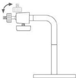
The camera comes with a camera stand (optional), which has a swivel ball screw head that can be attached to the camera's screw hole on the up (or bottom) panel. Attach the camera to the stand and station it for your application. There are three holes located in the base of the camera stand, allowing the camera to be mounted on the ceiling or any wall securely.
natural_image
Pure mechanical diagram of a pipe fitting with a valve and base, no text or symbols presentConnecting the Ethernet cable
Connect an Ethernet cable to the network cable connector located on the camera's rear panel, and then attach it to the network.

natural_image
Illustration of a hand inserting a device into a device with a pen (no text or symbols visible)Attaching the Power Supply
Attach the power supply's plug to the cable of the lens (1), and then connect the cable's plug to the power connector located on the camera's rear panel labeled DC 12V (2). Then, connect the power supply to the wall outlet (3).

TIP:
- When you are connecting the camera, always connect the Ethernet cable before connect the power supply.
- You can confirm the power source is supplied from the Power LED on the camera.
Replace the Lens Assembly
If required, you can replace the lens assembly with DC-Iris lens. First, remove the original lens by turning it in an anti-clockwise direction. (For detailed instructions, please refer to the section Replacing the Lens of Appendix - Adjusting Camera Focus.)
- Fit the additional lens onto the CS-mount ring and turn it in a clockwise direction (①).
- Then, plug the cable to the camera's DC-Iris connector (②).

natural_image
Illustration of a blue portable radio device with attached lens and cable (no text or symbols)TIP: When you replace a DC-Iris lens, you could adjust the brightness of the video images using the Iris Level screw-knob.

SECURITY
To ensure the highest security and prevent unauthorized usage of the camera, the administrator has the exclusive privilege to access the System Administration for settings and control requirements to allow users the level of entry and authorize the privileges for all users. The camera supports multi-level password protection. Accessing to the camera is strictly restricted to defined users with a "User Name" and "User Password", which are assigned by the administrator.
The administrator can release a public user name and password. Therefore, when remote users access the camera, they will have the right to view the image transmitted by the camera.
NOTE: Since the default settings are Null String, it is highly recommended to set the "Admin Password" when you are the first time to use the camera. Once the password is defined, only the administrator is permitted to manage the camera. The security feature of the camera will not be enabled until the "Admin Password" is defined; therefore, you have to complete this procedure as soon as possible.

APPLICATION OF THE CAMERA
The camera can be applied in wide variety of applications. It is an all-in-one device that can be attached directly to an Ethernet or Fast Ethernet network. With the built-in CPU, it can work as a standalone system that provides a web-based solution transmitting high quality video images and sounds for monitoring purposes. It can be managed remotely, accessed and controlled from any desktop/notebook PC over the Intranet or Internet via a web browser. With the easy installation procedure, real-time live images will be available. In addition, once the camera is installed coupled with the IPView SP application, you can further expand the scope of the camera.
The following section provides the typical applications for your camera with the IPView SP application, and also includes some basic knowledge to assist in the installation and configuration of the camera.
Applications
- Monitor local and remote places and objects through a web browser, such as construction sites, hospitals, parks, schools and day-care centers.
● Capture single frame images or video images from the IPView SP application. - Connect up to two external devices to the camera for alarm notifications; in addition, when the trigger is activated, you can configure the camera to send e-mail messages that attach the video clip (with sound).
Application Diagrams of the Camera
1. Home/Small Business Applications

flowchart
graph TD
    A["Internet"] --> B["Cable/DSL Modem"]
    B --> C["Firewall Router (TW100-BRF114)"]
    C --> D["Office Monitoring (TV-IP300)"]
    D --> E["Front Gate Monitoring (TV-IP300)"]
    E --> F["Workstation with PCI Adapter (TE100-PCIWN)"]
    F --> G["Warehouse Monitoring (TV-IP300W)"]
    G --> H["Wireless Access Point (TEW-230APB)"]
    H --> I["Parking Monitoring (TV-IP300W)"]
    I --> J["Internet"]
    style A fill:#cce5ff,stroke:#333
    style B fill:#cce5ff,stroke:#333
    style C fill:#cce5ff,stroke:#333
    style D fill:#cce5ff,stroke:#333
    style E fill:#cce5ff,stroke:#333
    style F fill:#cce5ff,stroke:#333
    style G fill:#cce5ff,stroke:#333
    style H fill:#cce5ff,stroke:#333
    style I fill:#cce5ff,stroke:#333
- I/O Connector Application

USING THE CAMERA
You can access and manage the Advanced Day/Night Internet Camera Server through: 1) a web browser, and 2) the enclosed software IPView SP. This chapter describes the Web Configuration Utility, and provides the instructions on using the camera with a web browser.
Web Configuration Utility
First, launch your web browser (such as the Internet Explorer 6.0 used in this manual). Then, type the default IP address http://192.168.0.30 in the Address bar and press [Enter] to enter the Welcome screen of the camera's Web Configuration Utility.
NOTE: The PC's IP address must correspond with the camera's IP address in the same segment for the two devices to communicate.

Welcome Screen of the Configuration Utility
The Welcome screen will appear to provide the following two items for selection:
- Client Settings
- System Administration
NOTE:
- Extensive knowledge of LAN will be helpful in configuring the camera.
- If the user is not allowed to control I/O output function, the user cannot see the I/O output trigger item on the Welcome screen when login. For more information, see the section Users in this chapter.
Client Settings

Under the Client Settings screen, the user can customize the configuration of the connected camera on individual platform, including the Media option and Protocol option. Please note that the configuration changed in Client Settings is only effective on the user's system.
For example, when the user selects "Disable audio" option, it means that the sound from the camera is muted on the individual system, but not to disable the camera's audio function.
The Protocol Option allows the user to select the transmission protocol depending on the networking status. The available options are UDP, TCP, and HTTP.
System Administration
Under the Welcome screen of the Configuration Utility, click System Administration to enter the administration window that contains the settings required for the camera in the top menu bar, including System, Video, Users, DateTime, Motion detection, Application, RS485 port, Information, Tools, and Home.

System
The System window contains commands for settings that are required for inputting key details to set up the camera for operation.
TIP:
- Once you have changed the settings in each option, click Save to store the settings, or Cancel to abandon. During the configuration, whenever you click Home in the top menu bar will make you return to the Welcome window.
- The System window is the initial window when you click the System Administration option. Alternately, you can click the System item in the top menu bar to enter the System window when you are in other configuration windows.
Camera Name
This field is used for entering a descriptive name for the device (a maximum of 32 characters, printable ASCII code).
Location
This field is used for entering a descriptive name for the location used by the camera.
Admin
This field is used for entering the Administrator password to access the System Administration settings. Enter the password in the Admin Password box, and then enter the same one again in the Confirm Password box to confirm the password.
The default setting for Admin is blank space (Null String). For security purpose, you are strongly recommended to set the Admin Password (a maximum of 8 characters) as soon as possible to enable security function for the camera.
IP Assignment
You can assign a proper IP address for the camera manually. The default settings are:
• IP Address - 192.168.0.30
- Subnet Mask - 255.255.255.0
- Default Gateway - 0.0.0.0
TIP: Accessing to the camera is done through assigning a proper IP address. Please make sure to use a vacant IP address when you assign the IP address for the Internet Camera. This will prevent errors from occurring if the IP address is overlapped.
UPnP
UPnP is the architecture for pervasive peer-to-peer network connectivity of intelligent appliances, wireless devices, and PCs of all form factors. Check the Enable option to enable the function of your camera.
DNS IP Address
DNS (Domain Name System) server is an Internet service that translates domain names into IP addresses. Enter at least one DNS IP address.
Dynamic DNS
Check the Enable option to enable the Dynamic DNS function, which allows you to run your domain over a changing IP address. Select one Dynamic DNS provider from the pull-down menu, and then enter the required information in the following fields, including the Host Name, User Name, and Password.
Wireless Interface (for wireless model)
If you use a wireless-enabled camera, you can configure the respective settings in this field, including:
- ESSID: This field is used to setup which wireless network (ESS-ID, Extended Service Set ID) the camera is to be connected for communication. The ESS-ID is a unique identifier shared among all points in a wireless network environment.
The default Network Name is blank space (NULL String), and this default setting will allow the camera to connect to ANY access point under the infrastructure network mode.
To connect the Advanced Wireless Day/Night Internet Camera Server to a specific access point on the network, please make sure to set the ESS-ID of the camera to correspond with the access point's ESS-ID for communication. Enter a name in the Network Name box (a maximum of 32 characters including spaces and symbols, the punctuation are not allowed).
To connect the camera to an Ad-hoc wireless workgroup, please make sure to set the same wireless channel and ESS-ID to match with the computer's settings for direct wireless communication under the Ad-hoc wireless workgroup.
- Wireless mode: Use this option to determine the type of wireless communication for the camera. The available
settings are Infrastructure mode and Ad-Hoc mode. The default setting is Infrastructure.
- Channel: The pull-down menu provides the wireless channel for communication. A "channel" is a range of frequencies to be used in communication between the camera and access point (Infrastructure mode) or the camera and computer (Adhoc mode). Select the appropriate channel from the list provided depending on the regulatory region where the unit is sold. The default setting is channel 6.
- TX rate: This option is used to set the current transmitting rate. The speed should be set to Auto rate to optimize performance and range, which will adjust the transfer speed for best performance and longest range automatically.
- Preamble: You can set the length of preamble by choosing Long preamble or Short preamble from the pull-down menu.
- Data Encryption: Wireless network communications can be intercepted easily. Enable this option will help you protect your wireless network. When enabled, choose the proper settings in the following options, including Auth mode, Key length, and Key format.
To enable WEP Encryption, you should decide the encryption format first by selecting the ASCII or HEX in Key format option, and then input the WEP key.
ASCII input format:
ASCII format causes each character you type to be interpreted as an eight-bit value. All unaccented upper- and lower-case Western European characters that can be input through your keyboard's typing zone are valid. To setup a 64-bit WEP key, input 5 ASCII characters. For example, '12345'. To setup a 128-bit WEP key, input 13 ASCII characters. For example, '1234567890123'. These character counts result in bit counts of 40 and 104
respectively; the camera will automatically pad your input to a bit count of 64 or 128.
HEX input format:
Hex format causes each pair of characters you type to be interpreted as an eight-bit value in hexadecimal (base 16) notation. Only the digits 0 through 9 and the letters A through F (in upper or lower case) are valid. To setup a 64-bit WEP key, input 10 HEX format. For example, '3132333435', which is the same with ASCII input '12345'. To setup an 128-bit WEP key, input 26 HEX format. For example, '31323334353637383930313233', which is the same with ASCII input '1234567890123'. These character counts result in bit counts of 40 and 104, respectively; the camera will automatically pad your input to a bit count of 64 or 128.
Network
This option allows you to set up networking configuration. The default port for communication is via port 80 (HTTP), and you can change it according to your network configuration.
- SMTP: If you enable the Send snapshot image by email function in the Application window, you have to configure the following settings in this field.
- SMTP (mail) server 1/2 - You must enter the mail server address in the field.
- Recipient email address 1/2 - Enter the e-mail address of the user who will receive the e-mail.
- Return email address – Enter the e-mail address of the user who will send the c-mail.
- FTP: If you enable the Upload snapshot image to FTP server function in the Application window, you have to configure the following settings in this field.
- Local FTP server port - The standard port number for the FTP server is Port 21, and it's also the default setting. If the FTP server uses a specific port, please confirm the IT manager.
- 1st/2nd FTP server - The IP Address of the target FTP server.
- 1st/2nd User Name/Password - Enter the user name and password in the two fields to login the FTP server.
-
1st/2nd FTP remote folder - Enter an existing folder name in this field, and the images will be uploaded to the specified folder.
-
HTTP: The default HTTP Port is 80.
- Streaming: Configure the transmission of streaming data within the network.
• Control channel port - The default is 8481.
• Video channel port - The default is 8483.
• Audio channel port - The default is 8482.
NOTE: When transferring the streaming data, the camera will check the HTTP port (port 80) first. If the port is allowed to use, the streaming data will automatically switch to port 8481 (control data), 8483 (video data) and 8482 (audio data). If not, the data will be transferred through port 80 only; then, the camera cannot send the images with sound (without audio data).
Video
The Video window contains commands to provide the settings for the images captured by the camera.
Click Video in the top menu bar and the Video window will appear as below:

Video Resolution
Select the desired video resolution from the two formats: CIF and QCIF. The default setting is CIF.
TIP: CIF is based on progressively scanned format (@ 30 frames/sec) with 352x 240 (NTSC) or 352x288 (PAL), while QCIF is 176x120 (NTSC) or 176x144 (PAL). In addition, CIF compatibility was made optional but QCIF compatibility is mandatory, i.e., all codecs must be able to operate with QCIF. CIF is primarily for videoconferencing, while QCIF is suitable for a desktop videophone.
Frame Rate
Select the optimal setting depending on your network status. Please note that the higher setting can obtain better quality; however, it will use more resource within your network. The available settings are 1, 3, 7, 15, 25 and 30 (for PAL system, the settings are 1, 3, 7, 15 and 25).
Video Quality
You can select the optimal setting depending on Fix bit rate or Fix quality. Please note that the higher setting can obtain better quality; however, it will use more resource within your network.
Up/Down reversal and Left/Right reversal options allow you to change the display of image.
Click Image Setting button to bring up the following window, which allows you to adjust the image setting:

When completed, click Save.
- Brightness: Adjust the brightness level.
- Contrast: Adjust the contrast level.
- Saturation: Adjust the colors level.
- Hue: Adjust the hue level.
Users
The User window contains commands that allow the system administrator to assign legal users who are permitted to monitor the camera from the remote site.
Click Users in the top menu bar and the Users window will appear as below:

Add User
- User Name: Enter the user name in this field (a maximum of 12 characters, printable ASCII code).
A maximum of 10 users names are allowed; however, each users name must be different. Each user name can be used as a group given the password. For example, if the User Name is "Guest" and the User Password is "Guest", anyone can access the camera with these details used as a group of users under the User Name "Guest".
NOTE: To get a better quality of video images and sounds through the network or Internet, the recommended users connected simultaneously should not exceed 10.
- User Password: Enter the user's password assigned by the administrator (a maximum of 8 characters, printable ASCII code).
- I/O Output Control: The administrator has the authority to give permission for the privilege to control the I/O Output Control to users.
- Upload image to FTP server: To upload the recorded image to the FTP server, check this option and enter the required information in the FTP field under the System window.
To add a new user, input the required information and then click Add.
Delete User
Select the user you want to delete from the pull-down menu, and then click Delete.
NOTE:
- Once the administrator has configured the users for the camera, any user will be required to enter a defined login password to access the camera.
- If the users login the Configuration Utility using their own user name and password, the available item for selection on the Welcome screen is Client Setting only.
- If the administrator enabled FTP function and set up the related settings, and allowed the user to control I/O output function, the user will see the related items (FTP upload information and I/O control buttons) displayed on the Welcome screen when login.
DateTime
The DateTime window contains commands to set up the camera's time and date, providing correct information to the remote users who might be thousands of miles away from the camera's location. You can set up the Time and Date manually or automatically by selecting the Synchronized with Time Server (Network Time Protocol) option.
Click DateTime in the top menu bar and the DateTime window will appear as below:

Date & Time
- Synchronized with Time Server: Select this option and the time will be based on GMT setting. When selecting the option, you have to enter the required information in the following fields:
-
IP Address - Enter the IP Address of the Time Server in this field.
-
TimeZone – Select the time zone for the region from the pull-down menu. (Please refer to the Appendix for the time zone selection table.)
- Set Manually: Select this option to set the time manually. The system administrator must enter the Date and Time in the respective field manually.
- Synchronized with computer: Select this option and the time will be based on the computer's setting.
NOTE: When you select Set Manually, every time when the camera is powered off and then powered on, you must re-enter the details once again.
Motion Detection
The Motion Detection window contains
Click Motion Detection in the top menu bar and the Motion Detection window will appear as below:
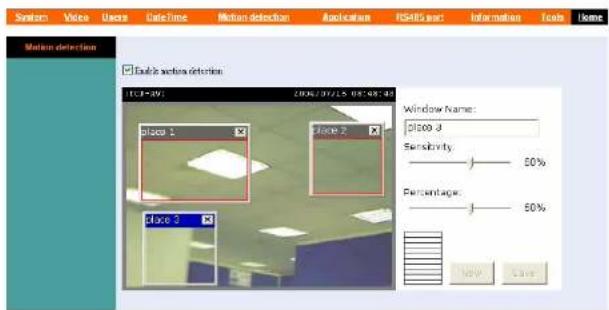
- Enable Motion Detection: Check this option to enable motion detection function of your camera. Once enabled, you can setup the detecting region by giving a Window Name. In addition, move the slide bars to adjust the Sensitivity level and Percentage level for detecting motion to record video.
TIP: You can add up to three detecting regions (windows) and adjust their positions for your needs.
Application
The Application window contains commands for the I/O Trigger connectors, providing the physical interface for two digital output/input to connect a diversity of external alarm devices, such as IR-Sensor and alarm relay.
Click Application in the top menu bar and the Application window will appear as below:
![System Video Users Data Time Motion detection Application I/O Input Trigger Trigger I/O output Send timestamp image by email Sending Interval : 5 seconds Upload timestamp image to FTP server Sending Interval : 5 seconds Read File Name : video Motion Detection Trigger I/O output Send timestamp image by email Upload timestamp image to FTP server Read File Name : video Scheduling Upload Time schedule Upload image to FTP server Always Schedule Day : □ Save □ Miss □ Tue □ Wed □ Thu □ Fri □ Set Time Period : Start : 01:07:01 [Deluxe] Step : 00:00:00 [Deluxe] Time Interval : 1 second](/content/2026/06/1189104/images/98bb6382bfdec4002a8d51803f9b973f4111e2ff3b3eb66ad588c5a81dbc7da1.jpg)
I/O Input Trigger
This item is used to set up the following related action(s) when the camera receives the signal from the I/O Input Trigger, including Trigger I/O output, Send snapshot image by email and Upload snapshot image to FTP server. To enable these actions, check the desired items and enter the required information.
Motion Detection
This item is used to set up the following related action(s) when the camera receives the signal from specified detection area, including Trigger I/O output, Send snapshot image by email and Upload snapshot image to FTP server. To enable these actions, check the desired items and enter the required information.
TIP: To send the snapshot image through e-mail, or upload the to the FTP server, check the related options and enter the required information in the SMTP and FTP fields under the System window.
Scheduling/Manual Upload
To upload the image to FTP server, you can choose Schedule Upload or Manual Upload. The Schedule Upload function will work after you have selected the Schedule option in the field and setup the Day and Time Period settings. Please note that you have to set up the related settings in the FTP field under the System window.
RS485 Port
The RS485 Port window contains the control settings for external device through the I/O port. You have to configure the respective settings in this window.
Click RS485 Port in the top menu bar and the RS485 Port window will appear as below:
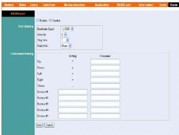
Check the Enable option to enable the function of your camera, and configure the related settings in the following fields. When you enable the port function, some control buttons will be added on the Home screen of Configuration Utility (as shown below).

Port Setting
Select the proper values from the pull-down menus in this field, including Baud rate, Data bit, Stop bits, and Parity bit.
Command Setting
According to the function of the external device you connected, you can customize more buttons for your need. Please note that the setting value in Command is provided by the connected external device.
Information
The Information window provides detailed information of the camera, including the Model Name, Firmware Version, Mac Address, IP Address and System Log.
Click Information in the top menu bar and the Information window will appear as below:
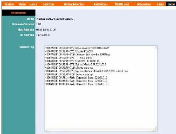
Model
The camera's model name will be display here.
Firmware Version
The field displays the firmware version of the camera.
MAC Address
This field displays the MAC Address of the camera.
IP Address
This field displays the IP Address of the camera.
System Log
This field displays the event log of the camera.
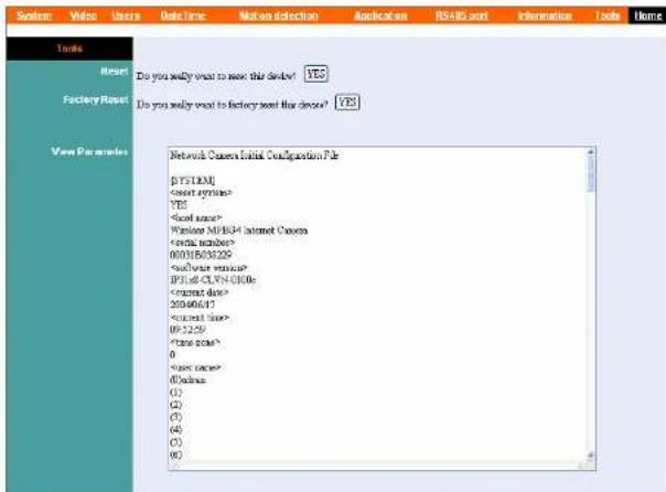
Tools
The Tools window contains commands for restarting the camera.
Click Tools in the top menu bar and the Tools window will appear as below:
Reset
Do you really want to reset this device? Click YES from this option, and you can restart the camera just like turning the device off and on and saved settings are retained. If you do not want to reset the camera, exit this window without clicking YES.
Factory Reset:
Do you really want to factory reset this device? Click YES from this option, and you can resume all factory default settings for the camera. If you do not want to restore the factory settings, exit this window without clicking YES.
NOTE: You have to configure the network settings again after a Factory Reset.
View Parameter
This field displays the configuration information of the camera.
Controlling I/O Output Trigger
On the Home screen of Configuration Utility, you can turn on/off the output device manually by clicking the ON/OFF button.


IPVIEW SP
This chapter describes the IPView SP, which is a powerful software application designed with a user-friendly interface for ease of control and navigation requirements.
Auto-Run Installation
Insert the software CD into the CD-ROM drive to initiate the Auto-Run program, and the menu screen will appear as below.

Then, select the desired options from the menu buttons, including the following options:
- Users Guide
- IPView SP
- IP Utility
- Browse CD
- Exit
To preview the User's Guide in PDF format for detailed information of the camera, click the Users Guide button.
To install IPAddress SP, click the IPAddress SP button button to activate the installation procedure. Please refer to the next section for detailed information on installing IPAddress SP, and Appendix A for installing IP Utility.
If you want to browse the contents of the software CD, click the Browse CD button and the contents of the CD will be available for preview.
To close the Auto-Run program, click the EXIT button.
Installing IPView SP Manually
If the Auto-Run program doesn't launch automatically, you can install IPView SP manually.
- On the Windows desktop, click Start at the taskbar and select Run...; type E:\IPViewSP\setup.exe in the Open box (where E is your CD-ROM drive) and click OK.

- Once executed, the Setup program will extract files to launch the InstallShield Wizard; then, click Next in the welcome screen of InstallShield Wizard.

- Read and accept the software's License Agreement; then, click Yes.

- Choose the destination location. If no specific requirement, leave the default setting and click Next.

- Select the program folder. If no specific requirement, leave the default setting and click Next.

- The InstallShield Wizard starts to install the software. The Progress bar indicates the installation is proceeding.

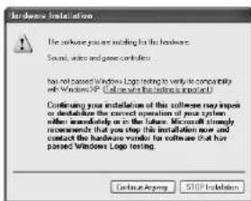
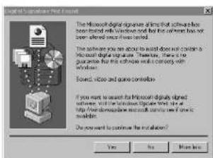
- If you use Windows® 2000/XP, it will appear a Digital Signature warning screen. Click Yes (Windows® 2000) or Continue Anyway (Windows® XP).
Windows® XP Windows® 2000
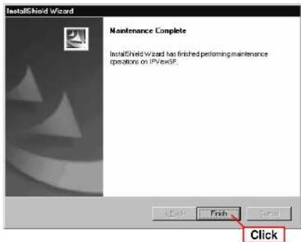
- Click Finish to complete the installation.

TIP: If you use Windows 98SE/ME, the system will ask you to reboot when the installation completed. Restart the system when prompted.
After successfully installing, the application program for the camera is automatically installed to your computer, and creates the IPViewSP folder in Programs of Start menu.
Uninstalling IPView SP
To uninstall IPView SP:
- Click Start and select Programs > IPViewSP, and then click Uninstall IPViewSP.

Alternately, you can click Start and select Settings, and then select Control Panel to open the Control Panel window. Double-click the Add/Remove Programs icon to open the Add/Remove Programs Properties window. Then, select the IPViewSP item by highlighting it and click Add/Remove...

- Select Uninstall and click Next when the InstallShield Wizard asks you to select the Setup type.

- Click OK when prompted to confirm uninstall.

- The InstallShield Wizard starts to uninstall the software. Click Finish when completed.
IPView SP – Getting Started
This section describes the operation of the IPView SP application User Interface with detailed procedures for using the application.
Launching IPView SP
To start running IPAddress SP, click Start and select Programs > IPAddress SP folder, and then select the IPAddress SP item.
IPView SP will bring up two screens: IPView SP screen and Display screen.
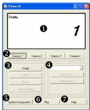
IPView SP screen
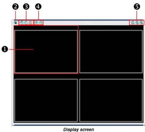
The following tables provide the description of components on the IPView SP screen and Display screen:
Components on IPView SP screen
| NO. | Component | Description |
| 1 | Camera Information Area | Display the general information of the connected camera, including the camera number, IP address, connect port, and on/off line status. |
| 2 | Camera (1~4) | Control 1~4 camera(s). |
| 3 | Connecting Control Area | This area provides four buttons to control the connect status of camera. The four buttons include: Assign, Connect/Disconnect, Erase, and Camera Setting.- Assign: Click to enter the IP Address (default setting: 192.168.0.30) of the camera in the pop-up dialog box. Then, click Add to add a new camera. If you are not sure of the camera's IP Address, you can click Browse to find the available camera; then, select the one you want (if more than one camera found) by highlighting it and click Add. In addition, you can select the protocol type from the pull-down menu: UTP, TCP, and HTTP. - Connect/Disconnect: The connected camera can be disabled temporarily by clicking Disconnect button. To resume the camera, click Connect.- Erase: Click to remove the connected camera from the list.- Camera Setting: Click to launch the Web Configuration Utility to change the settings. - Connect/Disconnect: The connected camera can be disabled temporarily by clicking Disconnect button. To resume the camera, click Connect.- Erase: Click to remove the connected camera from the list.- Camera Setting: Click to launch the Web Configuration Utility to change the settings. |
| 4 | Recording Control Area | This area provides recording function for the camera. You can select the recording mode from the pull-down menu: Manual Record. Schedule Record, and Motion Record.By default, the recorded video will be saved in a subfolder that is created automatically by the software and named as [camera number]_[camera IP address] under the IPView SP folder. You can change the settings in System Configuration. |
| 5 | System Configuration | This button is used to configure the system settings. |
| 6 | Play | Click to bring up IPView SP Player to play the recorded video clip. |
| 7 | Help | Click to bring up the help window. |
Components on Display screen
| NO. | Component | Description |
| 1 | View Window (1~4) | Display the video image from the active camera, including the current date and time. |
| 2 | Snapshot | Click the Snapshot button to capture a still image of the active camera. |
| 3 | View Mode Buttons | Select the view mode from the three buttons: Scan Mode, One Camera Mode, and Four Camera Mode.- Scan Mode Click to enable displaying the video images in circles. Please note that this mode needs two cameras on-line at least.- One Camera Mode Show one camera's video image in the whole display area.- Four Camera Mode Show four cameras' video images in the display area. |
| 4 | Select Buttons | Click the two buttons to select the active camera. |
| 5 | Window Control Buttons | Control the Display screen from the three buttons: Always on top, Minimum, and Maximum.- Always on top Keep the Display screen on top of the desktop.- Minimum Minimize the Display screen.- Maximum Maximize the Display screen. |
Using IPView SP
Adding a Camera
To add a new camera:
- Click the Camera button (1\~4) to bring up the following dialog box.
Alternately, you can directly click Assign button if you do not change the camera number.

- Enter the IP address of the camera (default: 192.168.0.30.) in the IP Address box and select the Protocol type (UTP, TCP, and HTTP) from the pull-down menu. Then, click Add to add a new camera.
If you are not sure of the camera's IP address, you can click Browse to search the available camera(s) within the network; then, select the one you want (if more than one camera found) by highlighting it and click Add.

- When the camera is added successfully, the video image from the camera will appear in the View Window corresponding to the camera number.
TIP:
- By default, you do not need to enter the User Name and Password to connect the camera.
- You can add only one camera at a time; if you want to add two or more cameras, please repeat the steps above.
Removing a Camera
The camera can be disabled temporarily or removed from the list.
- To disable the active camera temporarily, click Disconnect button. It will stop receiving the signal from the camera until you click Connect button.
- To remove the active camera, click Erase button. The camera will be removed from the list.
Viewing the Camera
From the Display screen, you can choose One Camera Mode or Four Camera Mode to display your video. A maximum of 4 cameras are available for viewing with the IPView SP. For example, if you use only one camera, click One Camera Mode button to display the video as figure 1.
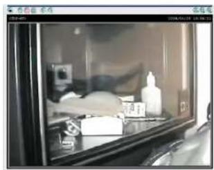
natural_image
Interior view of a glass-walled appliance with shelves, bottles, and accessories (no visible text or symbols)Figure 1.
If there are two or more cameras, click Four Camera Mode button 📋 to display the videos as figure 2.

natural_image
Four-panel collage showing outdoor scenes: a bridge, a high-rise building, a flat-screen TV, and a black-and-white photo (no visible text or symbols)Figure 2.
When multiple cameras connected, you can choose Scan Mode button ⚙ to display these videos as the main view in circles.
Capturing Image
IPView SP allows you to capture a still image and save it to your hard disk drive. To capture the image, simply click Snapshot button and select the folder you want to save the image.
Recording Video
IPView SP allows you to record the video clip and save it to your hard disk drive through the following methods: Manual Record, Schedule Record, and Motion Record.
Playing Recorded Video
The recorded video clips are saved on your hard disk drive and can be played on IPAddress SP Player. To launch the player, simply click the Play button on IPAddress SP screen. Alternately, you can click Start and select Programs > IPAddressSP, and then click IPAddressSP Player.

IPView SP Player
Then, you can click the Play button on the screen of IPAddress SP Player to play the videos saved in your hard disk drive.
Configuring the System
Click the System Configuration button on IPView SP screen, and you can configure the settings of you camera.

System Configuration Screen
System Setting
- Record Setting:
- Single HDD Reserved Space For OS – You can reserve 500 \~ 1000 MB hard disk space for the program.
- Split Recording File – If the recorded video files reach the file size limit, video images will be recorded into another file automatically. The available settings are from 10 \~ 50 MB.
- Storage List – The destination folder to save the recorded video file can be specified here. Click Modify to
change the current path setting; click Add to add a new destination folder; click Delete to remove a selected path setting. Please note that you are not allowed to delete a path setting if there is only one setting in the list.
- Email Setting: When the Send mail when motion detect item is checked, you should enter the required information in the respective fields, including Mail Server, Mail From, Mail To, Subject, User Name, Password, and Interval Time.
- Scan Delay: When multiple cameras connected, clicking the Scan Button allows you to display these views as the main view in circles, and you can adjust the scan delay time ranging from 1 \~ 20 seconds.
- Update Firmware: When new firmware is available, you can upgrade it through this window. Select the desired camera from the pull-down menu and click Browse to point to the firmware file in your computer, and then click Update to start.
Event
This screen shows the event logs of your camera(s).
About
This screen shows the information of IPView SP.

APPENDIX
A IP Utility
The Advanced Day/Night Internet Camera Server provides you with a convenient tool - IP Utility, which will help you search the connected Internet Camera(s) within your network easily and quickly. After connecting the camera, you can install the IP Utility in your computer from the Installation CD, and have the camera(s) in your network start to work.
To install IP Utility, insert the Installation CD into your CD-ROM drive of computer. When the Setup screen appears, click Install IP Utility. Then, follow the on-screen instruction to complete the installation.
To launch and use IP Utility, click Start > Programs > IPAddress SP > IP Utility. When you launch IP Utility, it starts to search the camera(s) within the network automatically. Then, the main window will appear as shown, and the result (connected camera) will be displayed in the list.
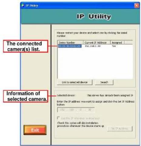
Control Buttons of IP Utility:
Click Search allows you to search the connected camera(s) again.
Click Link to selected device to launch the web Configuration Utility.
Click Set IP Address to change the selected camera's IP address.
Click Exit to close the Setup Wizard.
B Frequently Asked Questions
About Advanced Day/Night Internet Camera Server Features
Q: What is Advanced Day/Night Internet Camera Server?
A: The camera is a standalone system connecting directly to an Ethernet or Fast Ethernet network. Differed from the conventional PC camera, the camera is an all-in-one system with built-in CPU and web-based solutions providing a low cost solution that can transmit high quality video images for monitoring. The camera can be managed remotely, accessed and controlled from any PC/Notebook over the Intranet or Internet via a web browser.
Q: What is the maximum number of users that can be allowed to access the Advanced Day/Night Internet Camera Server simultaneously?
A: Maximum number of users that can log onto the camera at the same time is 10. Please keep in mind the overall performance of the transmission speed will slow down when many users are logged on.
Q: What algorithm is used to compress the digital image?
A: The camera utilizes the latest MPEG4 technology providing high quality images for users. You can record streaming video that utilizes high quality MPEG-4 images to your hard drive, enable motion detection and setup automated email alerts for security.
About Internet Camera Installation
Q: Can the Advanced Day/Night Internet Camera Server be used out-doors?
A: The camera is not weatherproof. It needs to be equipped with a weatherproof case to be used outdoors and it is not recommended.
Q: What network cabling is required for the Advanced Day/Night Internet Camera Server?
A: The camera uses Category 5 UTP cable allowing 10 Base-T and 100 Base-T networking.
Q: Can the Advanced Day/Night Internet Camera Server be setup as a PC-cam on the computer?
A: No, the camera is an Internet Camera used only on Ethernet and Fast Ethernet network.
Q: Can the Advanced Day/Night Internet Camera Server be connected on the network if it consists of only private IP addresses?
A: Yes. The camera can be connected to LAN with private IP addresses.
Q: Can the Advanced Day/Night Internet Camera Server be installed and work if a firewall exists on the network?
A: If a firewall exists on the network, port 80 is open for ordinary data communication. However, since the camera transmits image data, the default port 8481 is also required. Therefore, it is necessary to open port 8481 of the network for remote users to access the camera.
C PING Your IP Address
The PING (Packet Internet Groper) command can determine whether a specific IP address is accessible by sending a packet to the specific address and waiting for a reply. It can also provide a very useful tool to confirm if the IP address conflicts with the camera over the network.
Follow the step-by-step procedure below to utilize the PING command but first you must disconnect the camera from the network.
Start a DOS window. Type ping x.x.x.x and press [Enter], where x.x.x.x is the IP address of the camera.
The succeeding replies as illustrated below will provide useful explanation to the cause of the problem with the camera's IP address.
D Troubleshooting
Q: I cannot access the Advanced Day/Night Internet Camera Server from a web browser.
A: The possible cause might be the IP Address for the camera is already being used by another device. To correct the possible problem, you need to first disconnect the camera from the network. Then run the PING utility (follow the instructions in Appendix B - PING Your IP Address).
Another possible reason is the IP Address is located on a different subnet. To fix the problem, run the PING utility. If the utility returns “no response” or similar, the finding is probably correct, then you should proceed as below:
In Windows 98SE/ME/2000 and Windows NT, double check the IP Address of the camera is within the same subnet as your workstation.
Click Start > Setting > Control Panel, and then Network. Select TCP/IP from the Network dialog box, and then click Specify an IP address from the TCP/IP Properties dialog box. If the camera is situated on a different subnet than your workstation, you will not be able to set the IP address from this workstation. To verify make sure the first 3 sections of the IP address of the camera corresponds to the first 3 sections of the workstation. Therefore the IP address of the camera must be set from a workstation on the same subnet.
The other possible problems might be due to the network cable. Try replacing your network cable. Test the network interface of the product by connecting a local computer to the unit, utilizing a standard Crossover (hub to hub) Cable. If the problem is not solved, the camera might be faulty.
Q: Why does the Power LED not light up constantly?
A: The power supply used might be at fault. Confirm that you are using the provided power supply DC 12V for the camera and verify that the power supply is well connected.
Q: Why does the LAN LED not light up properly?
A: There might be a problem with the network cable. To confirm that the cables are working, PING the address of a know device on the network. If the cabling is OK and your network is reachable, you should receive a reply similar to the following (...bytes = 32 time = 2 ms).
Otherwise, the network device utilized by the camera is not functioning properly such as hubs or switches. Confirm the power for the devices are well connected and functioning.
Q: Why does the Advanced Day/Night Internet Camera Server work locally but not externally?
A: It may be caused from the firewall protection. Need to check the Internet firewall with your system administrator.
Otherwise, the default router setting might be a possible reason. Need to double check if the configuration of the default router settings is required.
Q: Why does a series of broad vertical white line appear through out the image?
A: A likely issue is that the CMOS sensor becomes overloaded when the light source is too bright such as direct exposure to sunlight or halogen light. You need to reposition the camera into a more shaded area immediately as this will damage the CMOS sensor.
Q: There is bad focus on the Advanced Day/Night Internet Camera Server, what should be done?
A: The focus might not be correctly adjusted for the line of sight. You need to adjust the focus manually as described in Adjust Camera Focus.
There is no adaptor fitted with your C-type lens. If you have previously changed the supplied CS-type lens, you may have unintentionally installed a C-type lens without fitting the adaptor first.
Q: Noisy images occur, how can I solve the problem?
A: The video images might be noisy if the camera is used is a very low light environment.
Q: There is poor image quality, how can I improve the image?
A: A probable cause might be the incorrect display properties configuration for your desktop. You need to open the Display Properties on your desktop and configure your display to show at least 65'000 colors for example at least 16-bit.
NOTE: Applying only 16 or 256 colors on your computer will produce dithering artifacts in the image.
Otherwise, the configuration of the camera's image display is incorrect. You need to adjust the related parameter for improving images through the Preview window under Web Configuration Utility, such as brightness, contrast, hue and light frequency. Please refer to the Web Configuration section for details.
Q: There are no images available through the web browser?
A: The ActiveX might be disabled. If you are viewing the images from Internet Explorer make sure ActiveX has been enabled in the Internet Options menu. Alternatively, you can use the Java Applet for viewing the required images.
E Time Zone Table
| (GMT-12:00) Enwetok, Kwajalein |
| (GMT-11:00) Midway Island, Samoa |
| (GMT-10:00) Hawaii |
| (GMT-09:00) Alaska |
| (GMT-08:00) Pacific Time (US & Canada): Tijuana |
| (GMT-07:00) Arizona |
| (GMT-07:00) Mountain Time (US & Canada) |
| (GMT-06:00) Central Time (US & Canada) |
| (GMT-06:00) Mexico City, Tegucigalpa |
| (GMT-06:00) Saskatchewan |
| (GMT-05:00) Bogota, Lima, Quito |
| (GMT-05:00) Eastern Time (US & Canada) |
| (GMT-05:00) Indiana (East) |
| (GMT-04:00) Atlantic Time (Canada) |
| (GMT-04:00) Caracas, La Paz |
| (GMT-04:00) Santiago |
| (GMT-03:30) Newfoundland |
| (GMT-03:00) Brasilia |
| (GMT-03:00) Buenos Aires, Georgetown |
| (GMT-02:00) Mid-Atlantic |
| (GMT-01:00) Azores, Cape Verde Is. |
| (GMT) Casablanca, Monrovia |
| (GMT) Greenwich Mean Time : Dublin, Edinburgh, Lisbon, London |
| (GMT+01:00) Amsterdam, Berlin, Bern, Rome, Stockholm, Vienna |
| (GMT+01:00) Belgrade, Brahlslava, Budapest, Ljubljana, Prague |
| (GMT+01:00) Brussels, Copenhagen, Madrid, Paris, Vilnius |
| (GMT+01:00) Sarajevo, Skopje, Sofija, Warsaw, Zagreb |
| (GMT+02:00) Athens, Istanbul, Minsk |
| (GMT+02:00) Bucharest |
| (GMT+02:00) Cairo |
| (GMT+02:00) Harare, Pretoria |
| (GMT+02:00) Helsinki, Riga, Tallinn |
| (GMT+02:00) Jerusalem |
| (GMT+03:00) Baghdad, Kuwait, Riyadh |
| (GMT+03:00) Moscow, St. Petersburg, Volgograd |
| (GMT+03:00) Nairobi |
| (GMT+03:30) Tehran |
| (GMT+04:00) Abu Dhabi, Muscat |
| (GMT+04:00) Baku, Tbilisi |
| (GMT+04:30) Kabul |
| (GMT+05:00) Ekaterinburg |
| (GMT+05:00) Islamabad, Karachi, Tashkent |
| (GMT+05:30) Bombay, Calcutta, Madras, New Delhi |
| (GMT+06:00) Astana, Almaty, Dhaka |
| (GMT+06:00) Colombo |
| (GMT+07:00) Bangkok, Hanoi, Jakarta |
| (GMT+08:00) Beijing, Chongqing, Hong Kong, Urumqi |
| (GMT+08:00) Perth |
| (GMT+08:00) Singapore |
| (GMT+08:00) Taipei |
| (GMT+09:00) Osaka, Sapporo, Tokyo |
| (GMT+09:00) Seoul |
| (GMT+09:00) Yakutsk |
| (GMT+09:30) Adelaide |
| (GMT+09:30) Darwin |
| (GMT+10:00) Brisbane |
| (GMT+10:00) Canberra, Melbourne, Sydney |
| (GMT+10:00) Guam, Port Moresby |
| (GMT+10:00) Hobart |
| (GMT+10:00) Vladivostok |
| (GMT+08:00) Singapore |
| (GMT+08:00) Taipei |
| (GMT+09:00) Osaka, Sapporo, Tokyo |
| (GMT+09:00) Seoul |
| (GMT+09:00) Yakutsk |
| (GMT+09:30) Adelaide |
| (GMT+09:30) Darwin. |
| (GMT+10:00) Brisbane |
| (GMT+10:00) Canberra, Melbourne, Sydney |
| (GMT+10:00) Guam, Port Moresby |
| (GMT+10:00) Hobart |
| (GMT+10:00) Vladivostok |
| (GMT+11:00) Magadan, Solomon Is., New Caledonia |
| (GMT+12:00) Auckland, Wellington |
| (GMT+12:00) Fiji, Kamchatka, Marshall Is. |
F Adjusting Camera Focus
The Advanced Day/Night Internet Camera Server features an exchangeable CS-type lens that can be used for different applications as necessary. It supports rotational focus control, so that the lens can be adjusted to focus under normal and stable conditions to maximize the image quality of the camera.
To adjust the focus of the lens, you need to turn the lens slowly in either clockwise or anti-clockwise direction until the desired image appears. DO NOT over turn the lens in either of the directions as it will be out of focus. Unless you want to substitute the lens, DO NOT unscrew more than 1.0mm apart from the Fixed Lens Assembly.
Keep in mind while adjusting the Internet Camera's focus you can review the image quality from the Web browser.

Camera Lens Assembly Adjust by turning in clockwise or anti-clockwise direction.
NOTE: You can further adjust the camera's image quality through the Preview window under Web Configuration Utility. Please refer to Web Configuration section for further details.
WARNING: Direct exposure to sunlight may cause permanent damage to the CMOS sensor. Therefore do not expose the camera's lens directly to sunlight. When operation is required in glaring light environment, it is recommended to use an iris lens.
The camera is designed for indoor usage and if your application requires prolong exposure to sunlight, a sun visor is recommended to protect the camera.
Replacing the Lens
Since the camera is designed with a CS- mount, the lens equipped with the camera can be replaced with any standard C or CS lens commonly used within the surveillance industry.
Follow the instructions below to replace the supplied lens with any C or CS type lens.
- Unscrew the camera's lens assembly.
- C-lens only, attach the new lens to a CS-C adapter
- Screw the new lens onto the Internet Camera. If appropriate, adjust the iris according to the prevailing light conditions.
- Refer to Adjusting the Camera Focus on the previous page.
- Refresh the web browser and monitor the results from the camera.
G Specification
Image Sensor
Resolution: 512x480 (NTSC), 512x576 (PAL)
Sensor: Sharp 1/4" type CCD
Lens assembly:
Focal Length: 6.0 mm
Aperture: f=1.8
Lens mounting: IR Lens, CS-mount type
Audio
MIC Input: Internal MIC (mono)
S/N ratio: More than 60dB
Frequency: 50 \~ 16000Hz
Video
Frame rate: 30fps @ CIF (NTSC);
25fps @ CIF (PAL)
Video resolution: CIF (352x240 NTSC, 352x288
PAL); QCIF(176x120
176x144 PAL)
Compression: MPEG4 short header mode
c o m p r
Automatic Gain Control: Yes
Automatic Exposure (AE): Yes
Automatic White Balance: Yes
Flickless function: Yes
System Hardware
CPU: Philips Trimedia PNX1300 VLIW DSP
RAM: 16MB
Flash ROM: 2MB
Embedded
Linux
LAN Connector: One RJ-45 port to connect to
10/100Mbps Ethernet, auto-sensed
Wireless LAN: IEEE 802.11g wireless LAN
Protocol support: HTTP, SMTP, FTP, Telnet, NTP, DNS,
DHCP, TCP/IP, DDNS, UPnP
Generic I/O Port:
Input: 1 set, 2-pin (photo coupler, 12Vdc 50mA
max.)
Output: 1 set, 2-pin (relay, 24VDC 1A / 125VAC
0.5A max.)
RS-485: 2-pin (half duplex)
Browser Support
• OS Support: Windows 98SE/ME/2000/XP
- System requirement:
CPU: Pentium III 350MHz or above
Memory Size: 128MB
Resolution: 800x600 or above
- Internet Explorer 5.0 or above
IPView SP Application
• OS Support: Windows 98SE/ME/2000/XP
• System requirement for IPView SP:
CPU: Intel Pentium 3 650MHz or above
Memory Size: 256MB
Resolution: 800x600 or above
Operating Environment
Operating temperature:
5ircC 40ircC
Storage temperature:
-25ircC 60ircC
Humidity:
5% \~ 95% non-condensing
EMI
FCC, CE, VCCI Class B
H Glossary of Terms
NUMBERS
| 10BASE-T | 10BASE-T is Ethernet over UTP Category III, IV, or V unshielded twisted-pair media. |
| 100BASE-TX | The two-pair twisted-media implementation of 100BASE-T is called 100BASE-TX. |
| A | |
| Applet | Applets are small Java programs that can be embedded in an HTML page. The rule at the moment is that an applet can only make an Internet connection to the computer form that the applet was sent. |
| ASCII | American Standard Code For Information Interchange, it is the standard method for encoding characters as 8-bit sequences of binary numbers, allowing a maximum of 256 characters. |
| ARP | Address Resolution Protocol. ARP is a protocol that resides at the TCP/IP Internet layer that delivers data on the same network by translating an IP address to a physical address. |
| AVI | Audio Video Interleave, it is a Windows platform audio and video file type, a common format for small movies and videos. |
B
BOOTP
Bootstrap Protocol is an Internet protocol that can automatically configure a network device in a diskless workstation to give its own IP address.
C
Communication Communication has four components: sender, receiver, message, and medium. In networks, devices and application tasks and processes communicate messages to each other over media. They represent the sender and receivers. The data they send is the message. The cabling or transmission method they use is the medium.
Connection In networking, two devices establish a connection to communicate with each other.
D
DHCP
Dynamic Host Configuration Protocol was developed by Microsoft a protocol for assigning dynamic IP addresses to devices on a network. With dynamic addressing, a device can have a different IP address every time it connects to the network. In some systems, the device's IP address can even change while it is still connected. DHCP also supports a mix of static and dynamic IP addresses. This simplifies the task for network administrators because the software keeps track of IP addresses rather than requiring an administrator to manage the task. This means a new computer can be added to a network without the hassle of manually assigning it a unique IP address. DHCP
allows the specification for the service provided by a router, gateway, or other network device that automatically assigns an IP address to any device that requests one
DNS
Domain Name System is an Internet service that translates domain names into IP addresses. Since domain names are alphabetic, they're easier to remember. The Internet however, is really based on IP addresses every time you use a domain name the DNS will translate the name into the corresponding IP address. For example, the domain name www.network_camera.com might translate to 192.167.222.8.
E
Enterprise network
An enterprise network consists of collections of networks connected to each other over a geographically dispersed area. The enterprise network serves the needs of a widely distributed company and operates the company's mission-critical applications.
Ethernet
The most popular LAN communication technology. There are a variety of types of Ethernet, including 10Mbps (traditional Ethernet), 100Mbps (Fast Ethernet), and 1,000Mbps (Gigabit Ethernet). Most Ethernet networks use Category 5 cabling to carry information, in the form of electrical signals, between devices. Ethernet is an implementation of CSMA/CD that operates in a bus or star topology.
F
Fast Ethernet Fast Ethernet, also called 100BASE-T, operates at 10
or 100Mbps per second over UTP, STP, or fiber-optic media.
Firewall
Firewall is considered the first line of defense in protecting private information. For better security, data can be encrypted. A system designed to prevent unauthorized access to or from a private network. Firewalls are frequently used to prevent unauthorized Internet users from accessing private networks connected to the Internet, especially Intranets all messages entering or leaving the intranet pass through the firewall, which examines each message and blocks those that do not meet the specified security criteria.
G
Gateway
A gateway links computers that use different data formats together.
Group
Groups consist of several user machines that have similar characteristics such as being in the same department.
H
HEX
Short for hexadecimal refers to the base-16 number system, which consists of 16 unique symbols: the numbers 0 to 9 and the letters A to F. For example, the decimal number 15 is represented as F in the hexadecimal numbering system. The hexadecimal system is useful because it can represent every byte (8 bits) as two consecutive hexadecimal digits. It is easier for humans to read hexadecimal numbers than binary numbers.
I
Intranet
This is a private network, inside an organization or company that uses the same software you will find on the public Internet. The only difference is that an Intranet is used for internal usage only.
Internet
The Internet is a globally linked system of computers that are logically connected based on the Internet Protocol (IP). The Internet provides different ways to access private and public information worldwide.
Internet address
To participate in Internet communications and on Internet Protocol-based networks, a node must have an Internet address that identifies it to the other nodes. All Internet addresses are IP addresses
IP
Internet Protocol is the standard that describes the layout of the basic unit of information on the Internet (the packet) and also details the numerical addressing format used to route the information. Your Internet service provider controls the IP address of any device it connects to the Internet. The IP addresses in your network must conform to IP addressing rules. In smaller LANs, most people will allow the DHCP function of a router or gateway to assign the IP addresses on internal networks.
IP address
IP address is a 32-binary digit number that identifies each sender or receiver of information that is sent in packets across the Internet. For example 80.80.80.69 is an IP address, it is the closet thing the Internet has to telephone numbers. When you "call" that number, using any connection methods, you get connected to the computer that "owns" that IP address.
ISP
ISP (Internet Service Provider) is a company that maintains a network that is linked to the Internet by way of a dedicated communication line. An ISP offers the use of its dedicated communication lines to companies or individuals who can't afford the high monthly cost for a direct connection.
J
JAVA
Java is a programming language that is specially designed for writing programs that can be safely downloaded to your computer through the Internet without the fear of viruses. It is an object-oriented multi-thread programming best for creating applets and applications for the Internet, Intranet and other complex, distributed network.
L
LAN
Local Area Network a computer network that spans a relatively small area sharing common resources. Most LANs are confined to a single building or group of buildings.
N
NAT
Network Address Translator generally applied by a router that makes many different IP addresses on an internal network appear to the Internet as a single address. For routing messages properly within your network, each device requires a unique IP address. But the addresses may not be valid outside your network. NAT solves the problem. When devices within your
network request information from the Internet, the requests are forwarded to the Internet under the router's IP address. NAT distributes the responses to the proper IP addresses within your network.
Network
A network consists of a collection of two or more devices, people, or components that communicate with each other over physical or virtual media. The most common types of network are:
LAN – (local area network): Computers are in close distance to one another. They are usually in the same office space, room, or building.
WAN - (wide area network): The computers are in different geographic locations and are connected by telephone lines or radio waves.
NWay Protocol
A network protocol that can automatically negotiate the highest possible transmission speed between two devices.
P
PING
Packet Internet Groper, a utility used to determine whether a specific IP address is accessible. It functions by sending a packet to the specified address and waits for a reply. It is primarily used to troubleshoot Internet connections.
PPPoE
Point-to-Point Protocol over Ethernet. PPPoE is a specification for connecting the users on an Ethernet to the Internet through a common broadband medium, such as DSL or cable modem. All the users over the Ethernet share a common connection.
Protocol
Communication on the network is governed by sets of rules called protocols. Protocols provide the guidelines devices use to communicate with each other, and thus they have different functions. Some protocols are responsible for formatting and presenting and presenting data that will be transferred from file server memory to the file server's net work adapter. Others are responsible for filtering information between networks and forwarding data to its destination. Still other protocols dictate how data is transferred across the medium, and how servers respond to workstation requests and vice versa. Common network protocols responsible for the presentation and formatting of data for a network operating system are the Internetwork Packet Exchange (IPX) protocol or the Internet Protocol (IP). Protocols that dictate the format of data for transferors the medium include token-passing and Carrier Sense Multiple Access with Collision Detection (CSMA/CD), implemented as token-ring, ARCNET, FDDI, or Ethernet. The Router Information Protocol (RIP), a part of the Transmission Control Protocol/Internet Protocol (TCP/IP) suite, forwards packets from one network to another using the same network protocol.
R
RARP
Reverse Address Resolution Protocol, a TCP/IP protocol that allows a physical address, such as an Ethernet address, to be translated into an IP address.
RJ-45
RJ-45 connector is used for Ethernet cable connections.
| Router | A router is the network software or hardware entity charged with routing packets between networks. |
| S | |
| Server | It is a simple computer that provides resources, such as files or other information. |
| SMTP | The Simple Mail Transfer Protocol is used for Internet mail. |
| SNMP | Simple Network Management Protocol. SNMP was designed to provide a common foundation for managing network devices. |
| Station | In LANs, a station consists of a device that can communicate data on the network. In FDDI, a station includes both physical nodes and addressable logical devices. Workstations, single-attach stations, dual-attach stations, and concentrators are FDDI stations. |
| Subnet mask | In TCP/IP, the bits used to create the subnet are called the subnet mask. |
| T | |
| (TCP/IP) | Transmission Control Protocol/Internet Protocol is a widely used transport protocol that connects diverse computers of various transmission methods. It was developed y the Department of Defense to connect different computer types and led to the development of the Internet. |
| Transceiver | A transceiver joins two network segments together. Transceivers can also be used to join a segment that uses one medium to a segment that uses a different medium. On a 10BASE-5 network, the transceiver connects the network adapter or other network device to the medium. Transceivers also can be used on 10BASE-2 or 10BASE-T networks to attach devices with AUI ports. |
| U | |
| UDP | The User Datagram Protocol is a connectionless protocol that resides above IP in the TCP/IP suite |
| ULP | The upper-layer protocol refers to Application Layer protocols such as FTP, SNMP, and SMTP. |
| User Name | The USERNAME is the unique name assigned to each person who has access to the LAN. |
| Utility | It is a program that performs a specific task. |
| UTP | Unshielded twisted-pair. UTP is a form of cable used by all access methods. It consists of several pairs of wires enclosed in an unshielded sheath. |
| W | |
| WAN | Wide-Area Network. A wide-area network consists of groups of interconnected computers that are separated by a wide distance and communicate with each other via common carrier telecommunication techniques. |
Windows Windows is a graphical user interface for workstations that use DOS.
Workgroup A workgroup is a group of users who are physically located together and connected to the same LAN, or a group of users who are scattered throughout an organization but are logically connected by work and are connected to the same network group.
Workstations Workstation refers to the intelligent computer on the user's desktop. This computer may be an Intel-based PC, a Macintosh, or a UNIX-based workstation. The workstation is any intelligent device a user works from.
Limited Warranty
TRENDware warrants its products against defects in material and workmanship, under normal use and service, for the following lengths of time from the date of purchase.
Internet Camera Server – 3 Years Warranty
If a product does not operate as warranted above during the applicable warranty period, TRENDware shall, at its option and expense, repair the defective product or part, deliver to customer an equivalent product or part to replace the defective item, or refund to customer the purchase price paid for the defective product. All products that are replaced will become the property of TRENDware. Replacement products may be new or reconditioned.
TRENDware shall not be responsible for any software, firmware, information, or memory data of customer contained in, stored on, or integrated with any products returned to TRENDware pursuant to any warranty.
There are no user serviceable parts inside the product. Do not remove or attempt to service the product by any unauthorized service center. This warranty is voided if (i) the product has been modified or repaired by any unauthorized service center, (ii) the product was subject to accident, abuse, or improper use (iii) the product was subject to conditions more severe than those specified in the manual.
Warranty service may be obtained by contacting TRENDware office within the applicable warranty period for a Return Material Authorization (RMA) number, accompanied by a copy of the dated proof of the purchase. Products returned to TRENDware must be pre-authorized by TRENDware with RMA number marked on the outside of the package, and sent prepaid, insured and packaged appropriately for safe shipment.
WARRANTIES EXCLUSIVE: IF THE TRENDWARE PRODUCT DOES NOT OPERATE AS WARRANTED ABOVE, THE CUSTOMER'S SOLE REMEDY SHALL BE, AT TRENDWARE'S OPTION, REPAIR OR REPLACEMENT. THE FOREGOING WARRANTIES AND REMEDIES ARE EXCLUSIVE AND ARE IN LIEU OF ALL OTHER WARRANTIES, EXPRESSED OR IMPLIED, EITHER IN FACT OR BY OPERATION OF LAW, STATUTORY OR OTHERWISE, INCLUDING WARRANTIES OF MERCHANTABILITY AND FITNESS FOR A PARTICULAR PURPOSE. TRENDWARE NEITHER ASSUMES NOR AUTHORIZES ANY OTHER PERSON TO ASSUME FOR IT ANY OTHER LIABILITY IN CONNECTION WITH THE SALE, INSTALLATION MAINTENANCE OR USE OF TRENDWARE'S PRODUCTS.
TRENDWARE SHALL NOT BE LIABLE UNDER THIS WARRANTY IF ITS TESTING AND EXAMINATION DISCLOSE THAT THE ALLEGED DEFECT IN THE PRODUCT DOES NOT EXIST OR WAS CAUSED BY CUSTOMER'S OR ANY THIRD PERSON'S MISUSE, NEGLECT, IMPROPER INSTALLATION OR TESTING, UNAUTHORIZED ATTEMPTS TO REPAIR OR MODIFY, OR ANY OTHER CAUSE BEYOND THE RANGE OF THE INTENDED USE, OR BY ACCIDENT, FIRE, LIGHTNING, OR OTHER HAZARD.
LIMITATION OF LIABILITY: TO THE FULL EXTENT ALLOWED BY LAW TRENDWARE ALSO EXCLUDES FOR ITSELF AND ITS SUPPLIERS ANY LIABILITY, WHETHER BASED IN CONTRACT OR TORT (INCLUDING NEGLIGENCE), FOR INCIDENTAL, CONSEQUENTIAL, INDIRECT, SPECIAL, OR PUNITIVE DAMAGES OF ANY KIND, OR FOR LOSS OF REVENUE OR PROFITS, LOSS OF BUSINESS. LOSS OF INFORMATION OR DATE, OR OTHER FINANCIAL LOSS ARISING OUT OF OR IN CONNECTION WITH THE SALE, INSTALLATION, MAINTENANCE, USE, PERFORMANCE, FAILURE, OR INTERRUPTION OF THE POSSIBILITY OF SUCH DAMAGES, AND LIMITS ITS LIABILITY TO REPAIR, REPLACEMENT, OR REFUND OF THE PURCHASE PRICE PAID, AT TRENDWARE'S OPTION. THIS DISCLAIMER OF LIABILITY FOR DAMAGES WILL NOT BE AFFECTED IF ANY REMEDY PROVIDED HEREIN SHALL FAIL OF ITS ESSENTIAL PURPOSE.
Governing Law: This Limited Warranty shall be governed by the laws of the state of California.
Technical Support
You can find the most recent driver/firmware/software and user documentations on the TRENDware website. TRENDware provides FREE technical support for all customers for the duration of the warranty period on this product.
TRENDware Technical Support
Tel: +1-310-626-6252
Fax: +1-310-626-6267
E-mail: support@trendware.com
www.TRENDnet.com
Monday \~ Friday, 7:30AM \~ 6:00PM Pacific
Standard Time
(Except holidays)

What's Next in Networking
Product Warranty Registration
Please take a moment to register your product online. Go to TRENDware's website at http://www.TRENDNET.com
TRENDware International, Inc.
3135 Kashiwa Street
Torrance, CA 90505
http://www.TRENDNET.com
Copyright ©2004. All Rights Reserved. TRENDware International, Inc.
- TABLE OF CONTENTS
- ABOUT THIS GUIDE
- Features and Benefits
- Simple To Use
- Support Variety of Platforms
- Web Configuration
- Remote Utility
- Connection to External Devices
- Broad Range of Applications
- RS-485 Support
- Day & Night Feature
- Unpacking the Package
- System Requirement
- Networking
- Local Area Network:
- Accessing the Camera
- For Web Browser Users
- For IPView SP Application Users
- Physical Description
- Link LED
- Power LED
- Internal MIC
- Lens Assembly
- External Antenna (for wireless model)
- Reset Button
- Network Cable Connector
- I/O Connector
- Iris Level
- DIP Switch
- DC Power Connector
- Top/Bottom Panel
- Screw Hole
- Side Panel
- DC-Iris Connector
- HARDWARE INSTALLATION
- Attaching the Camera to the Stand
- Connecting the Ethernet cable
- Attaching the Power Supply
- TIP:
- Replace the Lens Assembly
- SECURITY
- APPLICATION OF THE CAMERA
- Applications
- Application Diagrams of the Camera
- Home/Small Business Applications
- USING THE CAMERA
- Web Configuration Utility
- NOTE:
- Client Settings
- System Administration
- System
- Camera Name
- Location
- Admin
- IP Assignment
- UPnP
- DNS IP Address
- Dynamic DNS
- Wireless Interface (for wireless model)
- ASCII input format:
- HEX input format:
- Network
- Video
- Video Resolution
- Frame Rate
- Video Quality
- Users
- Add User
- Delete User
- DateTime
- Date & Time
- Motion Detection
- Application
- I/O Input Trigger
- Scheduling/Manual Upload
- RS485 Port
- Port Setting
- Command Setting
- Information
- Model
- Firmware Version
- MAC Address
- IP Address
- System Log
- Tools
- Reset
- Factory Reset:
- View Parameter
- Controlling I/O Output Trigger
- IPVIEW SP
- Auto-Run Installation
- Installing IPView SP Manually
- Uninstalling IPView SP
- IPView SP – Getting Started
- Launching IPView SP
- Using IPView SP
- Adding a Camera
- Removing a Camera
- Viewing the Camera
- Capturing Image
- Recording Video
- Playing Recorded Video
- Configuring the System
- System Setting
- Event
- About
- APPENDIX
- A IP Utility
- Control Buttons of IP Utility:
- B Frequently Asked Questions
- About Advanced Day/Night Internet Camera Server Features
- About Internet Camera Installation
- C PING Your IP Address
- D Troubleshooting
- Q: Why does the Power LED not light up constantly?
- Q: Why does the LAN LED not light up properly?
- Q: Why does the Advanced Day/Night Internet Camera Server work locally but not externally?
- Q: Why does a series of broad vertical white line appear through out the image?
- Q: There is bad focus on the Advanced Day/Night Internet Camera Server, what should be done?
- Q: Noisy images occur, how can I solve the problem?
- Q: There is poor image quality, how can I improve the image?
- Q: There are no images available through the web browser?
- E Time Zone Table
- F Adjusting Camera Focus
- Replacing the Lens
- G Specification
- Image Sensor
- Audio
- System Hardware
- Browser Support
- IPView SP Application
- Operating Environment
- EMI
- H Glossary of Terms
- B
- C
- D
- DNS
- E
- Enterprise network
- Ethernet
- F
- Firewall
- G
- Gateway
- Group
- H
- HEX
- I
- Intranet
- Internet
- Internet address
- IP
- ISP
- J
- JAVA
- L
- LAN
- N
- NAT
- NWay Protocol
- P
- PING
- PPPoE
- Protocol
- R
- RARP
- RJ-45
- Limited Warranty
- Technical Support
- Product Warranty Registration
Brand : TRENDNET
Model : TV-IP300W
Category : IP Camera