DTX1002-T - Network switch Black Box - Free user manual and instructions
Find the device manual for free DTX1002-T Black Box in PDF.


| Product Type | InvisaPC Transmitter (Network Switch / KVM Extender) |
| Model | DTX1002-T |
| Video Inputs | 2x DVI-D (digital only) |
| USB Interface | 1x USB Type B (for keyboard, mouse, and peripherals) |
| Network Interface | 1x RJ-45 10/100/1000 Mbps |
| Maximum Video Resolution | 1920 x 1200 @ 60 Hz, 24-bit color |
| Compression Algorithm | Dynamic Content Optimized Compression (DCOC) |
| Encryption | 128-bit |
| Power Source | External in-line power supply |
| Input Voltage | 100–240 VAC, 50/60 Hz |
| Power Consumption | 20 watts maximum |
| Heat Dissipation | 68.2 BTU/hour maximum |
| Operating Temperature | 32 to 104°F (0 to 40°C) |
| Storage Temperature | -4 to +140°F (-20 to 60°C) |
| Operating Humidity | 5 to 95%, noncondensing |
| Maximum Distance from CPU | 16 ft (5 m) due to DVI and USB cable limits |
| Maximum Distance between Transmitter and Receiver | 328 ft (100 m) over Ethernet; extendable with network switches |
| Supported Operating Systems | Microsoft Windows (Vista, 7, 8, 10, Server 2003/2008/2012), Linux, Mac OS, Solaris |
| Approvals | FCC Class A, TUV, CE, UL, CSA, RoHS, WEEE |
| Included Accessories (Kit DTX1002-T-K) | Transmitter unit, 2x DVI CPU cables, 1x USB CPU cable, power supply, power cord, Quick Installation Guide |
Frequently Asked Questions - DTX1002-T Black Box
User questions about DTX1002-T Black Box
0 question about this device. Answer the ones you know or ask your own.
Ask a new question about this device
Download the instructions for your Network switch in PDF format for free! Find your manual DTX1002-T - Black Box and take your electronic device back in hand. On this page are published all the documents necessary for the use of your device. DTX1002-T by Black Box.
USER MANUAL DTX1002-T Black Box
natural_image
Black Box electronic device with ports and indicator lights (no readable text or symbols)Trademarks Used in this Manual
Trademarks Used in this Manual
Black Box and the Double Diamond logo are registered trademarks of BB Technologies, Inc.
Any other trademarks mentioned in this manual are acknowledged to be the property of the trademark owners.
Federal Communications Commission and Industry Canada Radio Frequency Interference Statements
This equipment generates, uses, and can radiate radio-frequency energy, and if not installed and used properly, that is, in strict accordance with the manufacturer's instructions, may cause interference to radio communication. It has been tested and found to comply with the limits for a Class A computing device in accordance with the specifications in Subpart B of Part 15 of FCC rules, which are designed to provide reasonable protection against such interference when the equipment is operated in a commercial environment. Operation of this equipment in a residential area is likely to cause interference, in which case the user at his own expense will be required to take whatever measures may be necessary to correct the interference.
Changes or modifications not expressly approved by the party responsible for compliance could void the user's authority to operate the equipment.
This digital apparatus does not exceed the Class A limits for radio noise emission from digital apparatus set out in the Radio Interference Regulation of Industry Canada.
Symbols Used in this Manual
Symbols Used in this Manual

NOTE: This symbol alerts the user to the presence of important operating and maintenance (servicing) instructions in the literature accompanying the appliance.

WARNING: Dangerous Voltage: This symbol is intended to alert the user to the presence of uninsulated dangerous voltage within the product's enclosure that may be of sufficient magnitude to constitute a risk of electric shock to persons.

POWER ON: This symbol indicates the principal on/off switch is in the on position.

POWER OFF: This symbol indicates the principal on/off switch is in the off position.

PROTECTIVE GROUNDING TERMINAL: This symbol indicates a terminal that must be connected to earth ground prior to making any other connections to the equipment.
Table of Contents
Contents
- Specifications 8
- Overview 10
2.1 InvisaPC System Features 10
2.2 Overview of InvisaPC Devices....11
2.2.1 Video 11
2.2.2 Audio 11
2.2.3 Support for Keyboards, Mice, and USB Devices....11
2.2.4 IP Addressing 12
2.2.5 Firmware Upgrade 13
- InvisaPC Receivers 14
3.1 Configuration of Receiver....15
- InvisaPC Transmitters 16
4.1 Configuration of Transmitter 17
- InvisaPC Manager 18
5.1 Configuration of Manager 18
- Modes of Operation 19
6.1 Auto-Login 19
6.2 Auto-Connect....19
6.3 Private Connection 19
6.4 Shared Connection....19
- Application Examples ....20
7.1 Video, Audio, and USB Extension....20
7.2 Video, Audio, and USB Switching 20
-
InvisaPC Family 22
-
Installation 23
9.1 InvisaPC Receiver (DTX1000-R DTX1002-R) Checklist 23
Table of Contents
12.4 User Views and Capabilities 31
12.5 Connections Screen 31
12.5.1 Creating a New Connection 32
12.5.2 Connecting....34
12.5.3 Edit Connection.... 34
12.5.4 Remove Connection 34
12.6 Control Tab 34
12.6.1 Preferences 35
12.6.2 Network....38
12.6.3 System 39
12.7 Managing Users 46
12.7.1 Add a User....47
12.7.2 Auto Log-on 47
12.7.3 Edit a User 48
12.7.4 Remove a User 48
- Central Management ....50
13.1 Managing Devices....50
13.1.1 Discovering and Adding Devices 51
13.1.2 Adding a Device on your Network 51
13.1.3 Adding a Device not on your Network 52
13.1.4 Add Device via IP Address 53
13.1.5 Editing Managed Devices....53
13.1.6 Upgrading a Device Remotely....53
13.1.7 Licenses....54
Appendix. InvisaPC Video Resolutions Supported 55
Chapter 1: Specifications
- Specifications
| Approvals FCC, TUV, CE, UI, CSA, RoHS, WEEE | |
| Physical | |
| Computer Interface DTX1000-T, DTX1002-T: DVI-D cable, USB Type A to B cable | |
| Leads Supported | DTX1000-T, DTX1002-T: DVI-D video, USB keyboard, mouse, and peripherals, USB audio;DTX1000-R, DTX1002-R, DTX1032-R: DVI-D video, USB keyboard, mouse, and peripherals, analog audio; |
| LED Interface | (1) Power LED (green, located on front of the transmitters): Lights when power to the unit is ON;(1) Power LED button (green, located on front of the receiver or manager): Lights when power to the unit is ON;NOTE: Transmitter/Receiver or Manager turns on automatically and the LED lights when power to the unit is ON.(1) RJ-45 Speed LED (green, located on top left of RJ-45 connector);Blinks three times when the network connection is 1000 Mbps,Blinks two times when network connection is 100 Mbps,Blinks once when the network connection is 10 Mbps,Not blinking: No Link to network;(1) Activity LED (green, located on top right of RJ-45 connector):Solid green: Link up,Blinking: Activity on the link,OFF: No link |
| Maximum Distance from CPU to Transmitter | DTX1000-T, DTX1002-T: 16 ft. (5 m), DVI-D and USB limitations |
| Maximum Distance between Transmitter and Receiver | 328 ft. (100 m), use a network switch to get farther distances |
| Operating System Support Microsoft Windows | * Vista, XP, Windows 7, Windows 8, Server 2003, Server 2008, Server 2012, Linux *, Solaris, Mac OS |
| Connectors | DTX1000-T: (1) DVI input, (1) USB Type B female, (1) RJ-45 network 10/100/1000,(1) 2.5-mm barrel connector for power;DTX1000-R: (1) DVI output, (4) USB Type A female, (1) RJ-45 network 10/100/1000,(2) 3.5-mm connectors for microphone/stereo, (1) 2.5-mm barrel connector for power;DTX1002-T: (2) DVI input, (1) USB Type B female, (1) RI-45 network 10/100/1000,(1) 2.5-mm barrel connector for power;DTX1002-R: (2) DVI output, (4) USB Type A female, (1) RJ-45 network 10/100/1000,(2) 3.5-mm barrel connector for microphone/stereo, (1) 2.5-mm barrel connector for power;DTX1032-R: (1) DVI output, (4) USB Type A female, (1) RI-45 network 10/100/1000,(2) 3.5-mm connectors for microphone/stereo, (1) 2.5-mm barrel connector for power |
Dimensional Exclusivity: 1.20 ^1 H u € A/40Hz u € 31 ^1 Hz / 2 € u 12.95 o 10 mA sec
Chapter 1: Specifications
| 1. Specifications (continued) | |
| Power | |
| Power Source External in-line power supply | |
| Input Voltage 100–240 VAC, 50/60 Hz | |
| Input Current 0.9 amps maximum | |
| Power Consumption 20 watts | |
| Heat Dissipation | (5 VDC x 4 amps) x 3.41 = 68.2 BTU/hour maximum(Voltage x Nominal Current) x 3.41 = BTU/hr |
| Output Connector 2.5-mm barrel | |
| Input Connector IEC-320, CB | |
| Power Supply Cord Length 6 ft. (1.8 m) | |
| Environmental | |
| Operating Temperature 32 to 104°F (0 to 40°C) | |
| Storage Temperature -4 to +140°F (-20 to 60°C) | |
| Operating Humidity 5 to 95%, noncondensing | |
What's Included in the DTX1000-T-K and DTX1002-T-K Kits
The InvisaPC transmitter kits include the following items:
DTX1000-T-K includes:
• (1) DTX1000-T
• (1) DVI CPU Cable
• (1) USB CPU Cable
DTX1002-T-K includes:
• (1) DTX1002-T
• (2) DVI CPU Cables
• (1) USB CPU Cable
Chapter 2: Overview
2. Overview
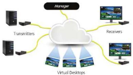
The InvisaPC system provides users with a seamless desktop experience anywhere on a TCP/IP network, while allowing the actual hardware to be securely housed in a corporate data center or in the cloud. InvisaPC enables the same high fidelity experience of a desktop PC even for media-rich applications, for example, watching videos, photo editing with Photoshop or 3D design with AutoCAD. The remote desktops may be hosted on a physical PC / workstation or may be a virtual desktop hosted on a private server or in the cloud. The InvisaPC system provides its users with Receivers that communicate with target computer nodes (whether physical PC or virtual desktop) over a standard TCP/IP network. Physical PCs/Workstations/Servers have an InvisaPC Transmitter unit physically connected to provide communication over the TCP/IP network. The performance of InvisaPC allows them to be deployed on standard corporate networks and even across Wide-Area-Networks (WANs).
Desktop users can access remote keyboard, mouse, video, audio, USB mass storage devices, headsets and other USB devices from the Receiver unit to the remote PCAworkstations or Virtual Desktop via the InvisaPC system.
NOTE: References to the InvisaPC system in this document refer to both Receivers (DTX1000-R, DTX1002-R) and Transmitters (DTX1000-T, DTX1002-T), and Manager (DTX1032-R).
flowchart
graph TD
    A["Manager"] --> B["Transmitters"]
    A --> C["Receivers"]
    A --> D["Virtual Desktops"]
    B --> E["Server 1"]
    B --> F["Server 2"]
    C --> G["Server 3"]
    C --> H["Server 4"]
Figure 2-1. InvisaPC System Example—including Physical and Virtual Desktops.
Transparent USB Re-Direction
The InvisaPC system provides transparent USB re-direction for both virtual and physical desktop connections. Keyboards and mice are collated to a common channel while other USB devices are re-directed to virtual or physical targets. There is a limit of two non-keyboard/mice devices that can be re-directed to a Transmitter unit (i.e. physical PC/Workstation).
Environmentally Optimized
The InvisaPC system is optimized to minimize power requirements and eliminate noise. All Receivers and Transmitters consume less than 6 Watts and are completely silent.
Easy Deployment
The InvisaPC system is designed to be easily and quickly deployed. No new drivers or software need to be installed on target PCs or Virtual Desktops. The system uses standard networking protocols and cabling. Users and connections are defined using an intuitive On-Screen-Display (OSD). Connections can be made via simple "click on target." Multiple modes of operation such as private connections, shared connections, auto-login, and auto-connect enable various workflows and collaborations to be supported.
2.2 Overview of InvisaPC Devices
The InvisaPC family is composed of Receivers, Transmitters, and System Managers. Some of the key capabilities and operation of InvisaPC devices are described below. These capabilities are supported across all InvisaPC devices.
2.2.1 Video
The InvisaPC system supports 24-bit color depth digital video up to a maximum resolution of 1920 x 1200 at 60 Hz for any video head on both Transmitter and Receiver. A DVI-I connector is provided on the Receiver, Transmitter, and Manager for cable compatibility, but only digital video is supported. See Appendix 1 - InvisaPC Video Resolutions Supported for the list of resolutions currently supported by InvisaPC. VGA or Analog video can be supported by using the KVGA-DVID VGA to DVI-D converter.
2.2.2 Audio
The InvisaPC system supports CD-quality stereo audio from the remote workstation (with the Transmitter connected) or virtual desktop to peripheral speakers connected to the USB connector on the InvisaPC Receiver. The InvisaPC Transmitter uses its USB interface to capture audio from the remote workstation. This increases audio quality by eliminating analog audio noise issues and removing the need for a sound card in PCWorkstation.
The InvisaPC Receiver connects audio from a peripheral microphone connected via the USB connector on the Receiver to the
Chapter 2: Overview
2.2.4 IP Addressing
The InvisaPC devices are IP-addressable, giving you the flexibility to locate workstations anywhere within your enterprise and at any distance from your desktop users. The InvisaPC devices use standard network protocols to transfer data between the remote Workstation/Virtual Desktop and the peripheral devices located at the user's desk. The InvisaPC system can operate on a network connection of 100 Mbps or 1 Gbps.
Chapter 2: Overview
2.2.5 Firmware Upgrade
Upgrade your firmware at any time using an InvisaPC manager or using a USB flash-drive in an InvisaPC Receiver unit to ensure that your InvisaPC system is always running the most current version available. All the InvisaPC devices - Receiver, Transmitter, and Manager - are upgradable.
Chapter 3: InvisaPC Receivers
3. InvisaPC Receivers
An InvisaPC Receiver connects to a physical PC or a virtual desktop over a TCP/IP network and decrypts and decompresses the streams to provide video, audio, and USB connections to a user. The user is presented with typical PC connections—video out (typically DVI), USB (typically 4 ports of USB 2.0), line out, and microphone in (see individual Receiver's data-sheets for specific ports provided).
The Transmitter-Receiver connection uses Black Box's compound compression algorithm for video called Dynamic Content Optimized Compression (DCOC). This algorithm optimizes compression based on content in the video stream and on available network bandwidth. Standard Microsoft RDP is used for connections to Virtual Desktops. Multiple versions of RDP are supported from RDP 8.1 to legacy versions. This allows InvisaPC Receivers to connect to Microsoft Hyper-V, VMware ESX, and Citrix XEN based virtual desktops as well as session host based desktops (previously called Terminal Services).
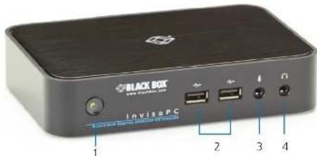
Figure 3-1. Front view of InvisaPC Receiver (DTX1000-R or DTX1002-R).

Table 3-1. InvisaPC Receiver components.
| Number in Figures 3-1 through 3-3 | Component Description | |
| 1. Power LED Lights green when power is on | ||
| 2. G (4) USB Type A connectors Link to USB devices | ||
| 3 (1) 3.5-mm connector Connects to microphone | ||
| 4 (1) 3.5-mm connector Connects to speakers | ||
| 5 (1) 2.5-mm barrel connector for power Links to 5-VDC external in-line power supply | ||
| 7 (1) Link/Activity LED Lights green when there is activity on the link | ||
| 8 (1) RJ-45 connector Links to 10/100/1000 Mbps network | ||
| 9 | (1) 10/100/1000 Mbps LED | Lights green when data is being received at 1000 Mbps |
| 10 (1) or (2) DVI output connectors Links to DVI outputs | ||
3.1 Configuration of Receiver
The Receiver is configured using an On-Screen Display (OSD) built into the Receiver or using the InvisaPC Manager. The network settings and unit name among others can be configured for a Receiver. The target connections are defined by their target name or IP address, log-in username/password, and TCP port number to be used. Users can be created and specific connections may be allocated to the different users.
A Receiver user profile is protected by username and password to permit different users to access the same unit securely.
Multiplatform support
InvisaPC is compatible with the following operating systems:
- Microsoft® Windows Desktop Operating Systems (e.g. Windows 7, Windows 8, Windows 10) and Microsoft Server Operating Systems (e.g., 2003, Server 2008, Server 2012)
- Linux ^49
• Mac OS*
The default keyboard drivers for these operating systems are supported by the InvisaPC system.
Chapter 4: InvisaPC Transmitters
4. InvisaPC Transmitters
An InvisaPC Transmitter converts the video, audio, and USB connections of a PC or Workstation to a format that can be connected and controlled over a TCP/IP network. The Transmitter connects to the DVI and USB ports of a PC or workstation. The Transmitter controls the connection to a remote Receiver and manages the flow of information to it. It converts and compresses video and audio information for transmission over standard TCP/IP networks, along with USB peripheral communications. All data communication uses 128-bit encryption.
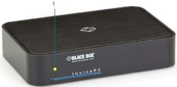
Figure 4-1. Front view of the InvisaPC Transmitter (DTX1000-T or DTX1002-T).
Chapter 4: InvisaPC Transmitters
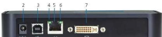
Table 4-1. Components of the InvisaPC Transmitter (DTX1000-T or DTX1002-T).
| Number in Figures 4-1 and 4-2 | Component Description | |
| 1 (1) Power LED Lights when power is on | ||
| 2 (1) 2.5-mm barrel connector for power Links to 5-VDC external in-line power supply | ||
| 3 (1) USB Type B connector Links to USB input device | ||
| 4 (1) Link/Activity LED Lights green when there is activity on the link | ||
| 5 (1) RI-45 connector Links to 10V/100V/1000 Mbps network | ||
| 6 | (1) 10V/100V/1000 Mbps LED | Lights green when data is being transmitted at 1000 Mbps |
| 7 (1) or (2) DVI input connectors Links to DVI input sources | ||
Chapter 5: InvisaPC Manager
The Transmitter uses Black Box's compound compression algorithm for video called Dynamic Content Optimized Compression (DCOC). This algorithm optimizes compression and latency on a frame-by-frame basis, depending on content in the video stream and on available network bandwidth. This enables an optimal user experience in challenging network environments.
4.1 Configuration of Transmitter
The Transmitter is configured from an InvisaPC Receiver or Manager. The network settings, unit name, and video quality are among the parameters that can be configured on a Transmitter.
Multiplatform support
The Transmitter is connected to the remote workstation via USB and DVI connectors. This enables the InvisaPC Receiver to inter-operate seamlessly with Windows, Linux®, and Macintosh© workstations/servers.
5. InvisaPC Manager (DTX1032-R)
An InvisaPC Manager (DTX1032-R) managing a network of InvisaPC Receivers and Transmitters can also act as an InvisaPC Receiver. The DTX1032-R can manage 32 transmitters/receivers by default. It can manage up to 250 transmitter/receivers when an upgrade license(s) (DTX1032-LIC100 / DTX1032-LIC250) is added to DTX1032-R.
NOTES: The front panel of the InvisaPC Manager (not pictured) looks similar to the InvisaPC receiver's (DTX1000-R or DTX1002-R) front panel shown in Chapter 3 of this manual.
The rear panel of the InvisaPC Manager (not pictured) looks similar to the DTX1000-R front panel shown in Chapter 3 of this manual.
5.1 Configuration of Manager
The Manager is configured using an On-Screen Display built into the Manager in the same manner as a Receiver.
A Manager user profile is protected by username and password to permit different users to access the same unit securely. It maintains the central database that is distributed to all Receivers in the "domain" of the Manager (i.e. discovered and added to manager) – called the "managed domain". This distribution ensures that there is no single point of failure in the InvisaPC system – each Receiver has a copy of the database. This enables each Receiver to continue operation – log users in, make connections as required – even if the Manager goes off-line.
Chapter 7: Application Examples
6. Modes of Operation
The InvisaPC system has various modes of operation such as Auto-Login, Auto-Connect, Private Connection, and Shared Connection Modes. The InvisaPC system can obtain their IP address data from a DHCP server in any of these modes or use static addresses.
6.1 Auto-Login
In Auto-Login Mode, turning on the InvisaPC Receiver automatically causes a login as a pre-defined user. The user is presented with the permitted connections that have been predefined.
6.2 Auto-Connect
In Auto-Connect Mode, when a user logs-in to the InvisaPC Receiver, it causes an automatic connection to their pre-allocated workstation or virtual desktop. Auto-Login and Auto-Connect are defined independent of each other.
6.3 Private Connection
In Private Connection Mode, when a user makes a connection to a target workstation/virtual desktop, this connection is only accessible by this user. All other users will receive a "busy" message if they attempt to connect to the same workstation/virtual machine. This is the default mode for connections.
6.4 Shared Connection
In Shared Connection Mode, multiple users can connect to the audio and video of the same target computer over the network. They arbitrate for control of the keyboard and mouse of that computer. Non-keyboard and mice devices are not supported on shared connections.
These various modes can be mixed on a particular Receiver and connection. For example Auto-Login and Auto-Connect can be combined to enable an InvisaPC. Receiver to automatically connect to a specific target workstation/virtual desktop when power is applied without any user intervention that might be required for Digital Signage or Kiosk type of deployments.
7. Application Examples
The InvisaPC system is built to be flexible so that it can be deployed in many different types of applications such as basic extension, switching applications (sometimes called matrix), cloud-based desktops, control rooms, digital signage, and kiosk applications and other applications in banking, financial services, broadcast, network operations, industrial, government and enterprise computing sectors. InvisaPC provides the state-of-the-art performance by:
• using digital sources for video and audio, hence removing analog noise issues or other potential environmental issues;
- using advanced optimized compression to enable visually lossless video over standard low-bandwidth networks rather than a proprietary connection or dedicated gigabit networks of many systems;
7.1 Video, Audio and USB Extension
Many applications require Video, Audio, or USB extension (or all three together) such as PC back-racking, board-room fit-out, remote monitoring, and digital signage.
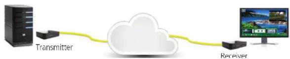
The InvisaPC system is setup to connect Transmitter to Receiver straight out of the box on a point-to-point network. The Transmitter and Receiver can be attached to standard Ethernet IP networks to increase the distance between units – within a building, between buildings, or across a country. Only standard Ethernet/IP rules and the maximum latency the application can tolerate need to be considered. If video and/or audio extension only is being used, latency rarely is a consideration as the traffic is typically one-way. When USB-based peripheral devices are also required a network latency of <50ms is recommended to avoid user issues with "poor mouse response", etc. For some applications, such as graphic design network latency, <20ms may be required to ensure user satisfaction. Latency normally is only an issue when extending across a WAN, because latency inside modern buildings or on dedicated networks are much less than 1 ms.
In Figure 7-1, a typical deployment is shown in a basic extender application. In this deployment, only one Transmitter and Receiver are used to allow remote access to a single workstation.
flowchart
graph LR
    A["Transmitter"] --> B["Cloud"]
    B --> C["Receiver"]
Chapter 8: InvisaPC Family
flowchart
graph TD
    A["Transmitters"] --> B["Cloud"]
    C["Receivers"] --> B
    D["Virtual Desktops"] --> B
    B --> E["Manager"]
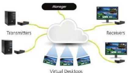
Figure 7-2. InvisaPC Switching Example.
8. InvisaPC Family
The InvisaPC system is composed of a family of Receivers, Transmitters, and Managers. The main difference between Receivers and Transmitters are on the number of video heads. The table below provides an example of products and part numbers.
Table 8-1. InvisaPC models.
| Receivers Number of Video Heads USB Ports | |
| DTX1000-R (1) DVI (4) USB 2.0 Type A | |
| DTX1002-R (2) DVI (4) USB 2.0 Type A | |
| Transmitters Number of Video Heads USB Ports | |
| DTX1000-T (1) DVI (1) USB 2.0 Type B | |
| DTX10002-T (2) DVI(1) USB 2.0 Type B | |
| Managers Number of Video Heads USB Ports | |
| DTX1032-R (1) DVI (4) USB 2.0 Type A |
Chapter 9: Installation
9. Installation
9.1 InvisaPC Receiver (DTX1000-R, DTX1002-R) Checklist
Before installing your InvisaPC Receiver, refer to the list below to ensure that you have all the items necessary for installation:
- InvisaPC Receiver
• External power supply for the InvisaPC Receiver - Power cord
• InvisaPC Quick Installation Guide (QIG)
9.2 InvisaPC Transmitter (DTX1000-T, DTX1002-T) Checklist
Before installing your InvisaPC Transmitter, refer to the list below to ensure that you have all the items necessary for installation:
- InvisaPC Transmitter
• External power supply for the InvisaPC Transmitter - Power cord
• InvisaPC Quick Installation Guide (QIG)
9.3 InvisaPC Transmitter Kit (DTX1000-T-K, DTX1002-T-K) Checklist
Before installing your InvisaPC Transmitter, refer to the list below to ensure that you have all the items necessary for installation:
- InvisaPC Transmitter
• External power supply for the InvisaPC Transmitter - Power cord
- DVI cable(s) (One DVI-D cable included for single head [DTX1000-T], two DVI-D cables needed for dual head [DTX1002-T])
- USB A to USB B Device cable
• InvisaPC Quick Installation Guide (QIG)
9.4 InvisaPC Manager (DTX1032-R) Checklist

WARNING: To avoid potentially fatal shock hazard and possible damage to equipment, please observe the following precautions:
- Test AC outlets at the workstation and monitor for proper polarity and grounding.
- Use only with grounded outlets at both the workstation and monitor. When using a backup Uninterruptible Power Supply (UPS), power the workstation and the Transmitter from the same supply.
NOTE: The AC inlet is the main disconnect.
9.6 Connect the InvisaPC Receiver
The recommended sequence to connect the Receiver is:
- Connect your keyboard, monitor, mouse, and other peripheral cables to the appropriately labeled ports on the InvisaPC Receiver.
- Connect the UTP cable to the RJ-45 port on the back of the Receiver.
- Plug the external power supply's 2.5 mm connector into the DC power jack on the rear of the InvisaPC Receiver.
- Connect the detachable power cord to the power supply.
- Plug the power cord into an appropriate wall outlet.
- Turn on the InvisaPC Receiver. A default connection is available to allow connection to a default InvisaPC Transmitter. You can use the OSD to add a different connection to a remote Transmitter or virtual desktop (see page 32 for details on how to add a connection). The default Transmitter IP address is 192.168.1.22.
- Once a Connection has been defined, use the OSD to make connection.
NOTE: VGA monitors can be connected to the InvisaPC Receiver by using a DVI-D to VGA converter (not adapter). Contact Black Box for recommendation if needed.
NOTE: When using the Receiver in single-head mode on a dual-head Receiver, the LEFT DVI connector is default as per the figure shown next.
Table 9-1. InvisaPC Receiver Connections components.
| Number in Figure 9-1 Type of Connector | |
| 1 ON/OFF button | |
| 2 USB Type A connector | |
| 3 USB Type A connector | |
| 4 Microphone | |
| 5 Speakers (Audio Line Out) | |
| 6 5-VDC Power IN | |
| 7 Dual USB Type A connector | |
| 8 RJ-45 port | |
| 9 DVI video |
9.7 Connect the InvisaPC Transmitter
Before connecting the InvisaPC Transmitter to the remote workstation, ensure that the resolution and the refresh rate of the remote workstation are supported by the InvisaPC system. Set the screen resolution and refresh rate of the remote workstation. Unsupported settings will cause blank or distorted video at the Receiver.
The recommended sequence to connect the Transmitter is:
- Turn off the remote workstation.
- The InvisaPC Transmitter has one USB connector. Connect it to a corresponding USB port on the remote workstation.
- Connect the video connector on the InvisaPC Transmitter to the appropriately labeled port on the workstation using the DVI cable.
- Connect one end of the UTP cable to the InvisaPC Transmitter's RJ-45 connector and turn on the workstation.
- Route the other end of the UTP cable to the location you have chosen for the InvisaPC Receiver. If necessary, you can extend the UTP cable via an Ethernet switch (subject to normal Ethernet cabling practices).
- Plug the external power supply's 2.5-mm connector into the DC power jack on the rear of the InvisaPC Transmitter.
- Connect the detachable power cord to the power supply.
Chapter 9: Installation
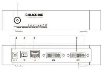
Figure 9-2. InvisaPC Transmitter connections.
Table 9-2. InvisaPC Transmitter Connections components.
| Number in Figure 9-2 Component | |
| 1 Power LED | |
| 2 5-VDC power inlet | |
| 3 USB Type B connector | |
| 4 RJ-45 port | |
| 5 DW video | |
9.8 Connect the InvisaPC Manager
The recommended sequence to connect the Manager is:
- Connect your keyboard, monitor, mouse, and other peripheral cables to the appropriately labeled ports on the InvisaPC
Chapter 10: Networked Installation
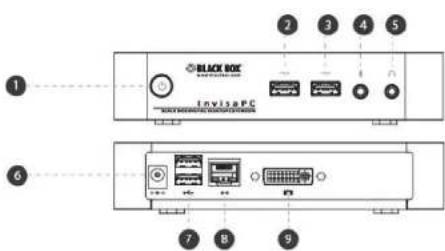
Figure 9-3. InvisaPC Manager Connections.
Table 9-3. InvisaPC Manager Connections components.
| Number in Figure 9-3 Component |
| 1 ON/OFF button |
| 2 USB Type A connector |
| 3 USB Type A connector |
| 4 Microphone |
| 5 Audio Line OUT |
| 6 5-VDC Power IN |
| 7 Dual USB Type A connector |
| 8 RJ-45 port |
| 9 DVI Video |
10. Networked Installation
10.1 Point-to-Point installation
In a point-to-point configuration, no administrator setup of the InvisaPC Transmitter or the InvisaPC Receiver is required. This enables you to install the system quickly, directly out-of-the-box. However, in the point-to-point configuration, you can install only one InvisaPC Transmitter and InvisaPC Receiver pair on a subnet, and both must be on the same subnet unless a router is present in the network to span subnets.
Also if there are other devices with 192.168.1.21 (default Receiver IP address) or 192.168.1.22 (default Transmitter IP address) on the network, then the IP addresses for Receiver and/or Transmitter should be changed to unused IP addresses.
10.2 Unmanaged or Managed Matrix Installation
The following instructions will enable you to install your InvisaPC Receiver and InvisaPC Transmitter in a networked configuration. In this installation, multiple InvisaPC Transmitters and InvisaPC Receivers are attached via the same Ethernet network. In this case, it is important for each unit to be configured with a unique IP address.
The InvisaPC Receiver has been preconfigured with factory-default network settings. If you install multiple units on the same network, you will need to assign a unique IP address to each unit or configure the Receiver for DHCP. This can be done via the On-Screen Display (OSD) on the InvisaPC Receiver and must be carried out before adding multiple devices on the same network.
Table 10-1. InvisaPC System Default Network Settings.
| Component | IP Address | Type | Default Gateway | Subnet Mask |
| InvisaPC Receiver (DTX1000-R or DTX1002-R) | 192.168.1.21 | Static | 192.168.1.1 | 255.255.255.0 |
| InvisaPC Transmitter (DTX1000-T or DTX1002-T) | 192.168.1.22 | Static | 192.168.1.1 | 255.255.255.0 |
| InvisaPC Manager (DTX1032-R) | 192.168.1.23 | Static | 192.168.1.1 | 255.255.255.0 |
Chapter 12: OSD Functions
11. Operation of the InvisaPC System
Operating a workstation through the InvisaPC system is no different than working directly connected to a PC desktop. All peripherals operate as if directly connected, even though the workstation is located at a distance.
11.1 LED Identification
Front panel
There is one LED on the front panel of an InvisaPC unit (integrated into the power-button on the Receiver and Manager) - called the STATUS LED. The STATUS LED will light up when the unit (Receiver, Manager, or Transmitter) is turned on. The STATUS LED "blinks" when a unit is being upgraded.
Rear panel
Two LEDs are built into the RJ-45 connectors on the InvisaPC Receiver, Manager and Transmitter. The definition of the operation of these LEDs is shown in Table 11-1.
Table 11-1. RJ-45 connector LEDs on the rear panel of the InvisaPC Receiver, Manager, and Transmitter.
| LED Status | Description | |
| Activity Green ON Linked OK | ||
11.2 Accessing the System
A connection is established using the OSD on an InvisaPC Receiver or Manager. Once you are connected, a series of messages will be displayed on the screen to inform you of the progress of the connection. You will be able to interact with the remote workstation as if it were located at your desk.
NOTE: If the remote workstation is powered off, the InvisaPC system will display a "black" screen for video when a connection is made.
12. OSD Functions
The InvisaPC Receiver and Manager incorporate an On-Screen Display (OSD) that allows you to view information about the configuration of your system and potentially also allows for setting connections and configuration parameters such as the IP address, depending on the type of user. The following sections describe the operation common on a Receiver or a Manager.
12.1 User Types
The InvisaPC system supports three classes of users for Matrix products:
- Administrator – users of this class have full rights to configure the system. They can create/modify/delete new users and connections, change network settings, etc.
- Power User – users of this class can modify resolution for connections to virtual desktops and change his/her local password.
- Standard User – users of this class can only select from a list of pre-defined connections to access and view system information. They cannot change any configuration settings.
12.2 Log-on
A user must log-on to the InvisaPC Receiver or Manager to configure and manage the InvisaPC system. The log-on screen is shown in Figure 12-1. The username defines the access rights and configuration available to the user.
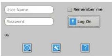
Figure 12-1. OSD Log-on Screen.
The fields on this screen are:
- Username: the username to loq-on as defined by the Administrator. Username is case-sensitive.
Chapter 12: OSD Functions
- System Preferences: This button has a drop down menu that allows the user to define system preferences for the InvisaPC Receiver. Figure 12-3 shows how the keyboard type can be selected.
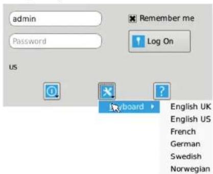
Figure 12-3. Setting Systems Keyboard Type.
Help: This button opens a pop-up window with help on that screen.
12.3 Default Username and Password
The InvisaPC Receiver and Manager ship with a default username of admin with a blank password (i.e. no password). This user cannot be deleted, but the password can be changed.
NOTE: If you create a password for the default Admin account and forget it, there is no way to reset / retrieve it.
We recommend that the administrator creates a second Admin account for critical systems in case the main Admin account is locked out.
12.4 User Views and Capabilities
There are three different types of users in the InvisaPC System. Your user type will determine what exactly you will see on your
Chapter 12: OSD Functions
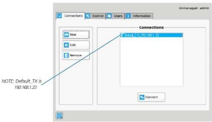
Figure 12-4. Connection Screen.
If the user is an Administrator type, the three buttons on the left (New, Edit, and Remove) will be displayed. These allow the user to create, edit, or remove connections. For Standard User types, no connections can be created, edited, or removed, so these buttons are not displayed.
By default, there is one connection called "Default Tx - 192.168.1.22" that defines a connection to an InvisaPC Transmitter with its factory defaults. A maximum of 32 connections can be defined for an InvisaPC Receiver or Manager by default, and these connections can be shared by users as defined by an administrator (different users can have the same connection). The number of connections can be increased to 250 in a managed domain via upgrade licenses.
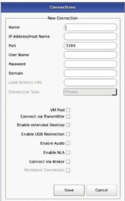
12.5.1 Creating a New Connection
To allow an InvisaPC Receiver or Manager to connect to a target InvisaPC Transmitter, an administrator must create a connection
Chapter 12: OSD Functions
Chapter 12: OSD Functions
Connect via Broker: when set, this enables the end user to connect to an available desktop via a connection broker.
Persistent Connection: When turned on, Persistent Connection will constantly try to connect to the Receiver until successful. This is useful when using InvisaPC for digital signage or an application that does not need a keyboard/mouse to stay connected to a defined source.
12.5.2 Connecting
To make a connection, the user highlights the required "connection" in the window and then clicks on the "Connect" button. Alternatively, a user can double-click on the connection. This action causes the InvisaPC Receiver to attempt to connect to the target remote workstation or virtual machine. If the target is available, the connection will be made.
If another user is already connected to the target defined in the connection, the user will receive a pop-up window indicating the target device is already allocated.
12.5.3 Edit Connection
To edit a connection and change its parameters, an administrator clicks on the Edit button on the Connections screen (shown in Figure 12-6). The Edit Connections pop-up window appears.
The administrator changes required fields and clicks Save to confirm or Cancel to discard any changes.
12.5.4 Remove Connection
To remove or delete a connection, an administrator highlights a connection in the list and then clicks on the Remove button on the Connections screen (shown in Figure 12-6). This causes the Remove Connection pop-up window to appear where a user confirms the removal or cancels the attempt.
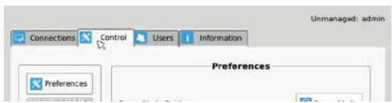
12.6 Control Tab
The Control Tab on the OSD enables an administrator to change the configuration of the InvisaPC system. The Control Tab is shown in Figure 12-6.
Chapter 12: OSD Functions
ii. Resolution Settings – allows change of preferred resolution for OSD screens and Virtual connections.
iii. Hot-Key Settings – allows changing of the active hot-key for keyboard short-cuts.
iv. Timer Settings – allows setting of pre-emption timer and various inactivity timers
2. Network – allows administrator to change network parameters for the InvisaPC Receiver or Manager.
3. System – allows upgrading of unit firmware, reset unit to factory defaults, and to save/restore unit configuration to a USB drive.
4. Password – change the administrator or user password.
5. Transmitter – allows changing of Transmitter parameters.
12.6.1 Preferences
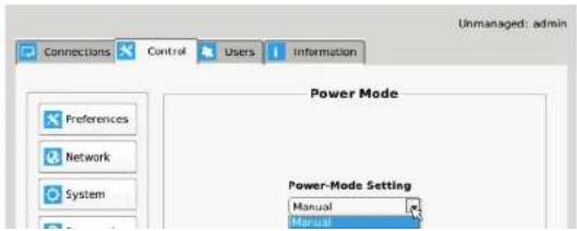
Power Mode
The Power Mode button allows the administrator to change the power mode configuration. The administrator can set the power mode to be Manual or Desktop Mode, which allows users to decide when to power up. A user has to push the power-button on the front of the Receiver or Manager to cause the Receiver to power up. When a unit is powered up, pressing the power-button for 3 seconds will cause the unit to power-off.
The Auto (Signage) mode automatically powers up the device when it's connected to power. You don't need to push the power button. This is typically the mode used for cases where a user wants the Receiver to power-up automatically when power is applied such as in Digital Signage or Kiosks. When the Receiver is in Auto mode, the power-button is disabled and not used to power-up or power-down the unit.
Chapter 12: OSD Functions
Resolution
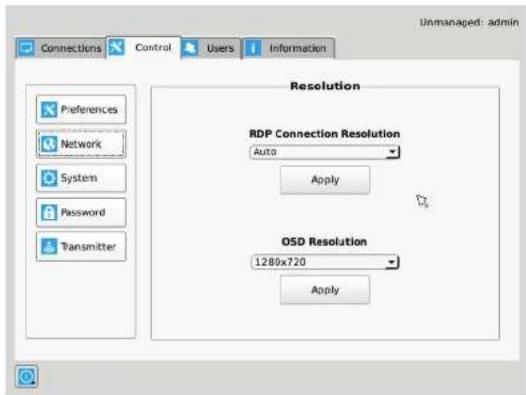
The Resolution button allows an administrator or power user to set the preferred resolution for the RDP Connection and for the OSD. By default, both the RDP Resolution and the OSD Resolution are set to Auto. Only Administrators and Power Users can change resolutions.
The RDP Connection Resolution allows the resolution to be changed for an RDP connection, i.e. defines the resolution that the virtual desktop will be accessed with. If the preferred resolution is not supported, the Receiver will use the next highest resolution supported by both monitor and Receiver.
The OSD Resolution is set to Auto by default, but can be changed to the available OSD resolutions if the user wants to set a specific resolution. This setting has no effect when connecting to an InvisaPC Transmitter.
Click Apply button to save the change.
Chapter 12: OSD Functions
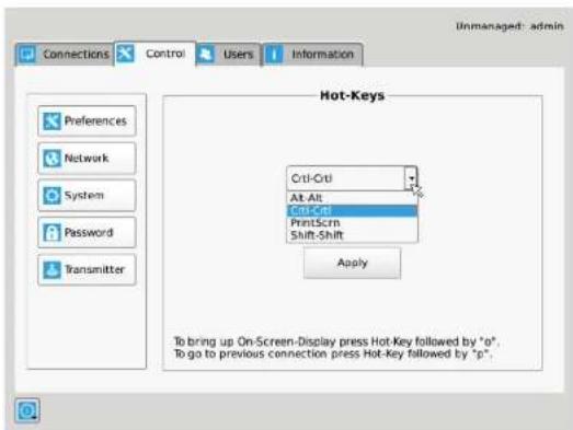
Figure 12-9. Hot Key Definition.
The default hot-key is Print-Screen (PmtScm). The alternatives are shown in the table. Click the Apply button to confirm a hot-key change.
Table 12-1. Hotkey sequences.
| Sequence Action | |
| Print Screen (Default) -press Pmt Scm key | |
| Ctrl + Ctrl -press Ctrl key twice within 1 second | |
| Alt + Alt -press Alt key twice within 1 second | |
| Shift + Shift -press Shift key twice within 1 second | |
Chapter 12: OSD Functions
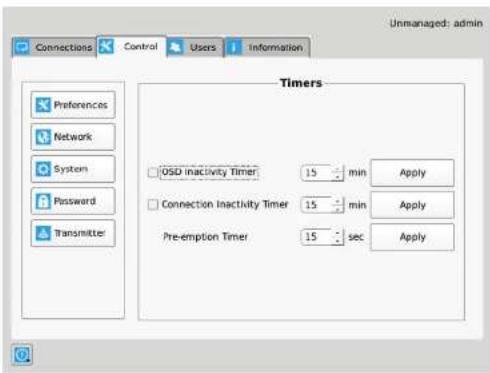
Figure 12-10. Timer Settings.
12.6.2 Network
The network screen shown in Figure 12-11 allows an administrator to change the settings for the InvisaPC Receiver or Manager. The default network setting for the Receiver is a static IP address of 192.168.1.21. It has a Network Mask of 255.255.255.0 and a Gateway 192.168.1.1. If DHCP is selected, the Receiver or Manager gets its IP address from the DHCP server. Click the Apply button to confirm any changes to network settings.
NOTE: Only IPv4 addressing supported in current firmware version.
Chapter 12: OSD Functions
12.6.3 System
The System screen shown in Figure 12-12 allows an administrator to upgrade the firmware in the InvisaPC Receiver or Manager, reset it to factory defaults, import/export the configuration to an external USB drive, and perform a system diagnostic.
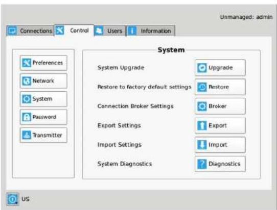
Figure 12-12. System Screen.
System Upgrade
The InvisaPC Receiver or Manager can be upgraded from a USB flash drive. Simply take the "firmware.clu" file and place it in the root directory of the flash drive. When you click the Upgrade button, the "valid" upgrade files on the USB drive are displayed. A valid file has the extension .clu – an example is shown in Figure 12-13. If the flash drive isn't recognized, format the drive with Fat32.
The administrator can click the Restore button to reset the Receiver or Manager back to factory defaults.
Connection Broker Settings
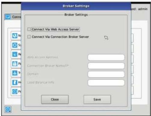
Figure 12-14. Connection Broker Setting Screen.
The Web Access Server setting is used to allow access to a local copy of Active Domain server. If this setting is configured correctly, then if a user who if not configured in the local database attempts to login, the device will redirect the username and password to the local active directory installation and validate the user credentials.
If the user is validated, the Active Directory Server will return a valid VM pool-name to the device. The device sends this pool-name information to the Connection Broker which then allocates a Virtual Machine to the User provided a VM is available.
Chapter 12: OSD Functions
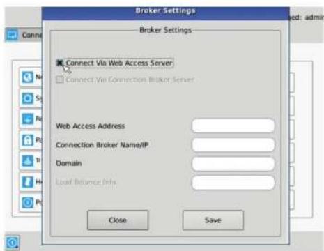
Figure 12-15. Connection Broker Settings for Web Access Server.
- Enter the local Connection Broker IP address.
- Enter in the local domain name.
Alternatively, the user credentials can be validated by using the local Connection Broker. In this case, the User Credentials are sent to the Connection Broker. If accepted, then the broker will return the IP address of a local VM from the pool and a connection is made.
NOTE: We currently do not cater for hostnames, so use the IP of the connection broker server.

Chapter 12: OSD Functions
-
Enter in the domain name as defined on the local network.
-
Enter in your load balance address as defined in the local server configured, e.g. tsv//VMResource.1.Win7Pool.
Export Settings
The Export option exports an encrypted version of the Receiver configuration to an attached memory stick. This can be used as a backup mechanism for an individual receiver or manager or it can be used to port configurations from one Receiver to another.
The data in the export file consists of User, Connection and device information from the exporting device.
Import Settings
The Import option imports an encrypted version of a Receiver or Manager configuration from an attached memory stick. This can be used to recover an old backup from the same Receiver or Manager or it can be used to port configurations from another Receiver.
The data in the file consists of User, Connection and some device information from the exporting device.
The following settings are not imported.
-
OSD Preferred Resolution
-
Power Mode Settings
-
Static IP address. In this case, if the importing device is set to static but the import file has a DHCP configuration, then the device configuration is changed to DHCP. Likewise, if the local device was DHCP and the import file was Static, the device configuration is change to Static but with its last configured Static IP address, not that of the imported file. If both local device and import file have a Static IP address configured, there is no change to the device configuration, i.e. the IP address is not changed.
NOTE: If the import function is on the Manager, then the file must come from another Manager with the same Licensed Capabilities or the import will not proceed.
System Diagnostics
The diagnostics provides information for Black Box to debug customer encountered issues. When this button is clicked the user is asked to save the diagnostics onto a memory stick in the Receiver unit. This file should be sent back to Black Box for analysis. There is a similar diagnostic that can be run on a transmitter (see page 46).
Chapter 12: OSD Functions
Transmitter Button
The Transmitter button on the Control Tab allows administrators to change the configuration of an InvisaPC Transmitter (this button is only visible to administrators). The following options are available when the Transmitter button has been activated:
- Transmitter Information
- Transmitter Firmware Upgrade
- Transmitter restore factory defaults
- Transmitter re-boot
- Video Quality Settings
- Network Settings
- Discover Transmitter IP address
Configuring a Transmitter
To configure a Transmitter, the IP address must be defined for the target Transmitter. When there is no active IP address defined, the TX Setting window has all the buttons grayed out except for the Apply and Discover buttons.
Enter the Transmitter's IP address directly and click the Apply button. If a valid IP address is entered, the TX Setting window makes all the options available for the administrator as shown in Figure 12-18.
NOTE: The default network setting for the Transmitter is a static IP address of 192.168.1.22. It has a Network Mask of 255.255.255.0 and a Gateway 192.168.1.1.
Chapter 12: OSD Functions
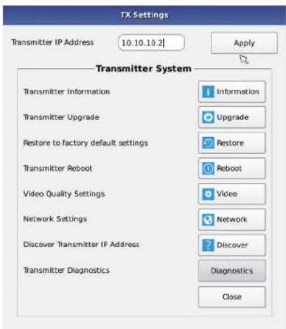
Figure 12-18. Transmitter Settings Configuration Window - Active IP Address.
If the IP address of the Receiver and Transmitter are not on the same subnet, a router is required to allow them to communicate. This is true even when the Receiver "discovers" the Transmitter's IP address. One way to avoid this is to change the Receiver address to be on the same subnet as the Transmitter, make the required configuration changes to the Transmitter, and then change the Receiver back to its required IP address.
Transmitter Information
The Information button provides Transmitter related information such as Device Model, Serial Number, MAC address, and current
Chapter 12: OSD Functions
Transmitter Reboot
The administrator can click the Reboot button to power-cycle the Transmitter. If the active IP address is not the address of a valid InvisaPC Transmitter or this address is unreachable, an error message is returned.
Transmitter Video Quality Settings
The administrator can click the Video Quality Settings button to change the video quality of the Transmitter. The Video Quality Settings can be set as follows, where 1 is best video quality and 5 is best video compression.
- Best Quality – lossless compression, pixel-perfect mode of operation. Generally needs dedicated network to ensure no frame loss.
- Visually Lossless Compression – high quality visual image. Some compression on stream to reduce bandwidth to allow operation on standard corporate networks. Compression does not vary based on available network bandwidth, so may lead to some dropped frames during network congestion periods.
- Optimized Quality (default) – system tuned to maintain visually lossless compression while increasing compression level during periods of network congestion to reduce frame loss. Balances visual quality with frame loss in periods of congestion (i.e. attempts to reduce/eliminate frame loss).
- Optimized Bandwidth – system tuned to maintain visually lossless compression but increased levels of compression level during periods of network congestion to reduce frame loss. Optimized towards lower bandwidth during congestion periods compared to level 3.
- Lowest Bandwidth – high level of compression to minimize average network bandwidth. No dynamic change to compression levels – always seeking to reduce bandwidth.
If the active IP address is not the address of a valid InvisaPC Transmitter or this address is unreachable, an error message is returned.
Transmitter Network Settings
The administrator can click the Network Settings button to cause the Transmitter Network Settings window to be displayed.
To change the IP address settings for a Transmitter at the active IP address, the administrator can enter the new IP address, subnet mask, and gateway, and then click on the Apply button.
If the new IP address for the InvisaPC Transmitter is on a different subnet than the Receiver, the Receiver or Manager will not be able to communicate with it without going through a router. This is the case even on a point-to-point link between devices. If the entered IP address is not the address of a valid InvisaPC Transmitter or this address is unreachable, an error message is returned.
Discover Transmitter IP Address
This requires the Transmitter to be connected to the Receiver or Manager on a point-to-point link or be the only Transmitter on the attached network. In this case, the administrator can click on the Discover button and follow the wizard to discover the IP address of the attached Transmitter. This is required in the case when an administrator does not know the IP address of the Transmitter.
Transmitter Diagnostics
The Transmitter provides diagnostics information for Black Box to debug customer encountered issues. When this button is clicked the user is asked to save the diagnostics onto a memory stick in the Receiver unit. Send this file back to Black Box for analysis.
12.7 Managing Users
Users are defined in the InvisaPC system to provide rights to manage the system, rights to connect to different target devices and set parameters for connections. There are three types of users that can be created in an InvisaPC system.
- Administrator – users of the class have full rights to configure the system. They can create/modify/delete new users and connection, change network settings, etc.
- Power User – users of this class can modify resolution for connections to virtual desktops and change his/her local password.
- Standard Users – users of this class can only select from a list of pre-defined connections to access and view system information. They cannot change any configuration settings.
The InvisaPC Receiver and Manager have one default user – admin, which is a member of the administrator group. This user is defined by default and cannot be deleted. An InvisaPC Receiver or Manager can have a maximum of 32 users defined, unless in a manager domain with "upgrade" license installed. With the upgrade license installed up to 250 users can be defined.
To manage users, an administrator selects the Users tab (this Tab is only visible to Administrator class users).
Chapter 12: OSD Functions
12.7.1 Add a User
To add a user, click the add button. This causes the New-User window to be displayed shown in Figure 12-18.
12.7.2 Auto Log-on
When the Log-on button is selected and a user is chosen, this user will be automatically logged on after power applied to unit or after a reboot.
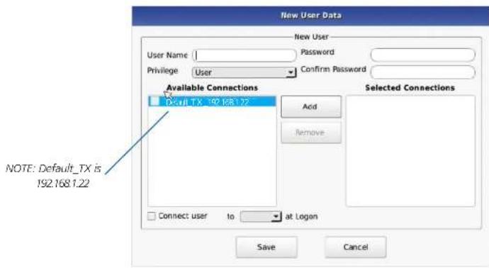
Figure 12-21. New User Window.
When adding a new user, the following fields are used to define the user:
- User Name: This is a unique name that uses 1–32 characters. The username can be any valid username for a Microsoft O/S. This means the username cannot contain “/A[];;| = , + * ? < >”.
- Password: This field can be a minimum of 0 characters (i.e. blank) and a maximum of 37 characters. The usomamo can be any
Chapter 12: OSD Functions
The Cancel button should be clicked if the new user is not to be created.
12.7.3 Edit a User
To edit a user, click on the Edit button. This causes the Edit-User window (shown in Figure 12-22) to be displayed.
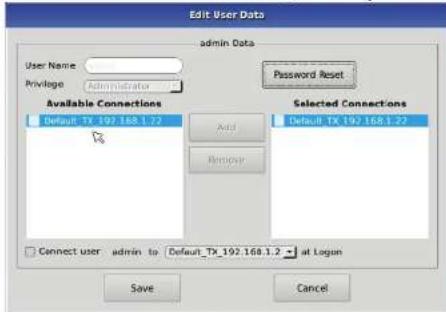
Figure 12-22. Edit User Window.
This window allows the user privilege type, the permitted connections available, the password, and the auto-connect option to be changed.
The default "admin" account gets access to all connections; this list cannot be modified. Other administrator-type users can have their connection list modified.
Once the changes have been made for a user, they only become active once the Save button has been clicked. The changes can be abandoned by clicking the Cancel button.
12.7.4 Remove a User
To remove a user, highlight the user's name and press "Remove."
Unmanaged: admin
Chapter 13: Central Management
NOTE: There must always be a user of the name admin in the InvisaPC system so the system can always be administrated. When attempting to remove the user, the system checks if the username is admin before it will allow the user to be removed.
Chapter 13: Central Management
13. Central Management
An InvisaPC system can be composed of just Receivers and Transmitters. In these types of systems – called unmanaged – there is no central management. Each device needs to be configured individually and upgraded individually. Often to keep the system in sync, the admin exports the configuration from one receiver and imports it to all other receivers using a USB Flash Drive.
For larger configurations, a central manager is needed. For InvisaPC systems this central manager is the DTX1032-R. The DTX1032-R can operate as a central manager for a "managed domain". A managed domain is a collection of InvisaPC Receivers and Transmitters managed by the DTX1032-R. Once a Receiver or Transmitter has been added to a managed domain, it can only communicate with other Receivers or Transmitters within this managed domain. They are not able to communicate to "unmanaged" devices or devices part of a different managed domain (i.e. a domain managed by a different DTX1032-R). The DTX1032-R can also operate as a receiver within its managed domain.
A DTX1032-R configures users, connections, hot-keys, and other parameters in the same way as described in section 10. The database created on the DTX1032-R is copied to each receiver on a user login. If the DTX1032-R for the managed domain is not reachable (e.g., powered-down), the Receiver will use the last updated database. This ensures that there is no single point of failure in the managed domain. Users can log in and connections can be made even if the manager of the domain is not reachable.
When a Receiver is managed, most of the configuration options on the OSD are disabled (i.e., grayed out). These configuration options can only be updated on the manager.
The Manager device has an extra tab on its OSD - Devices Tab. Use it to create and manage the DTX1032-R domain.
13.1 Managing Devices
The Devices Tab on the OSD enables an Administrator to centrally manage the configuration of other InvisaPC devices that are part of this manager's domain. The Devices Tab is shown in Figure 13-1.
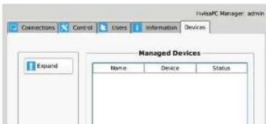
Chapter 13: Central Management
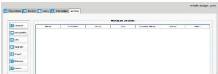
Figure 13-2. Device Tab Expanded.
13.1.1 Discovering and Adding Devices
Using the Discover button is the best way to add devices to your managed devices. When you click the Discover button, the manager will look for unmanaged devices on the network. These devices will appear in the Discovered Devices section as shown next. This shows the MAC Address, IP Address, Net Mask, Gateway, Device Type, and the Discover State (managed, unmanaged, or orphaned) of the devices discovered.
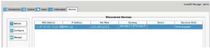
Figure 13-3. Discovered Devices.
13.1.2 Adding a Device on your Network
If the device you have discovered is on your network, you can simply click the Manage button. You will then be asked to give this
Chapter 13: Central Management
If a device has a managed state of "Orphaned", then there is a conflict between the reported state on the Manager and that of the device. This may occur where the device was removed from the Manager's database when the device was off-line, or if the Manager was restored to factory default settings. A device in the orphaned state can be set back to "Managed" by selecting the Manage button and following the same process as for unmanaged devices.
13.1.3 Adding a Device Not on Your Network
If the device is on a different network, it cannot be managed it directly (e.g. on a different subnet with no router between devices). It will need its network settings changed. To do this, click the device you want to manage and press the configure button. A dialog box will appear. This will allow you to change the network settings so the device is on your network.
![Discovered Appliance Appliance Network Settings MAC 1c:37.bf:00:10:22 IP Address 192.168.1.22] Network Mask 255.255.255.0 Default Gateway 192.168.1.1 Back Apply](/content/2026/05/925174/images/56d6070d135de409693a2afd5b3aefe47750d4fd1f7c7ab7467ed56622f569ef.jpg)
Figure 13-5. Appliance Network Settings.
Once you complete this step, the system will bring you back to the Discovered Devices page where you can see the network information has been changed. You can now select the device and click the Manage button. You will then be asked to give this device a name and it will be added to your Managed Devices section. We highly recommend giving all devices a unique name. Press the Back button to go back to the Managed Devices page, where you will see the device you have added.
Chapter 13: Central Management
13.1.4 Add Device via IP Address
The Add Device section only applies to devices that are on the same network as the manager. The Add Device pop up window allows the administrator to add a device using the device's IP address. Once you have entered in the device's IP address and press next, a dialog box appears. You will then be asked to give this device a name and it will be added to your Managed Devices section. We highly recommend giving all devices a unique name.
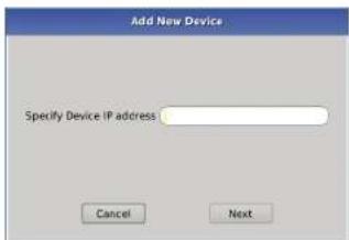
Figure 13-7. Add New Device.
13.1.5 Editing Managed Devices
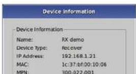
After selecting a device, the administrator can edit that device by pressing the Edit button. The Edit dialog box is shown in Figure 13-8. This enables the administrator to edit device information remotely. The administrator can restore to factory default settings, reboot the device, change network settings and view device information. If you want to delete a device from your managed devices list, press the Restore button. This restores the device to its factory default settings (this removes it from your managed devices).
Chapter 13: Central Management
Once this is successful, you can select the devices you wish to upgrade and select the Upgrade button.
NOTE: The device can only be upgraded if it is online.
You can check what upgrade releases you have on the Manager at any stage by pressing the Releases button. You can compare this to the software version on the managed devices via the information shown in the Managed Devices section.
13.1.7 Licenses
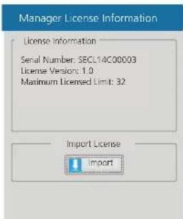
Administrators can see the available Licenses in their system via the License button. They can also Import Licenses via USB Flash Drive. Place the upgrade file received from Black Box in the root directory of the flash drive. Press the License button. This will pop-up a window that shows the Serial Number of the unit and the current License limit. By default this is 32 (i.e. 32 users, 32 connections).
To upgrade, press the Import button shown below. Once this is successful you will see your new License information appears. There are 100 and 250 upgrade licenses available.
NOTE: You need to increase your limit to 100 licenses before increasing it to 250 licenses. This requires the administrator to import the 100 license key first and then import the 250 license key after the 100 license key was imported successfully.
Appendix. InvisaPC Video Resolutions Supported
The InvisaPC supports the resolutions listed below:
- 640 x 480 @ 60 Hz
- 640 x 480 @ 75 Hz
- 800 x 600 @ 60 Hz
- 800 x 600 @ 70 Hz
- 800 x 600 @ 72 Hz
- 800 x 600 @ 75 Hz
- 800 x 600 @ 85 Hz
• 1024 x 768 @ 60 Hz
• 1024 x 768 @ 75 Hz
• 1024 x 768 @ 85 Hz
• 1280 x 800 @ 60 Hz
• 1280 x 960 @ 60 Hz
• 1280 x 960 @ 85 Hz
• 1280 x 1024 @ 60 Hz
• 1280 x 1024 @ 75 Hz
• 1280 x 1024 @ 85 Hz
• 1366 x 768 @ 60 Hz
- 1400 x 1050 @ 60 Hz
• 1440 x 900 @ 60 Hz
. \$600,000 @ 011-
NOTES
NOTES
NOTES
Black Box Tech Support: FREE! Live. 24/7.
Tech support the way it should be.

natural_image
Close-up portrait of a smiling man with short hair, wearing a cap and beard (no visible text or symbols)Great tech support is just 60 seconds away at 877-877-2269 or blackbox.com.

BLACK BOX®
- Trademarks Used in this Manual
- Federal Communications Commission and Industry Canada Radio Frequency Interference Statements
- Symbols Used in this Manual
- Table of Contents
- Contents
- Chapter 1: Specifications
- What's Included in the DTX1000-T-K and DTX1002-T-K Kits
- Chapter 2: Overview
- Overview
- Transparent USB Re-Direction
- Environmentally Optimized
- Easy Deployment
- Overview of InvisaPC Devices
- Video
- Audio
- IP Addressing
- Firmware Upgrade
- Chapter 3: InvisaPC Receivers
- InvisaPC Receivers
- Configuration of Receiver
- Multiplatform support
- Chapter 4: InvisaPC Transmitters
- InvisaPC Transmitters
- Chapter 5: InvisaPC Manager
- Configuration of Transmitter
- InvisaPC Manager (DTX1032-R)
- Configuration of Manager
- Chapter 7: Application Examples
- Modes of Operation
- Auto-Login
- Auto-Connect
- Private Connection
- Shared Connection
- Application Examples
- Video, Audio and USB Extension
- Chapter 8: InvisaPC Family
- InvisaPC Family
- Chapter 9: Installation
- Installation
- InvisaPC Receiver (DTX1000-R, DTX1002-R) Checklist
- InvisaPC Transmitter (DTX1000-T, DTX1002-T) Checklist
- InvisaPC Transmitter Kit (DTX1000-T-K, DTX1002-T-K) Checklist
- InvisaPC Manager (DTX1032-R) Checklist
- Connect the InvisaPC Receiver
- Connect the InvisaPC Transmitter
- Connect the InvisaPC Manager
- Chapter 10: Networked Installation
- Networked Installation
- Point-to-Point installation
- Unmanaged or Managed Matrix Installation
- Chapter 12: OSD Functions
- Operation of the InvisaPC System
- LED Identification
- Front panel
- Rear panel
- Accessing the System
- OSD Functions
- User Types
- Log-on
- Default Username and Password
- User Views and Capabilities
- Creating a New Connection
- Connecting
- Edit Connection
- Remove Connection
- Control Tab
- Preferences
- Power Mode
- Resolution
- Network
- System
- System Upgrade
- Export Settings
- Import Settings
- System Diagnostics
- Transmitter Button
- Configuring a Transmitter
- Transmitter Information
- Transmitter Reboot
- Transmitter Video Quality Settings
- Transmitter Network Settings
- Discover Transmitter IP Address
- Transmitter Diagnostics
- Managing Users
- Add a User
- Auto Log-on
- Edit a User
- Remove a User
- Chapter 13: Central Management
- Central Management
- Managing Devices
- Discovering and Adding Devices
- Adding a Device on your Network
- Adding a Device Not on Your Network
- Add Device via IP Address
- Editing Managed Devices
- Licenses
- Appendix. InvisaPC Video Resolutions Supported
Brand : Black Box
Model : DTX1002-T
Category : Network switch