
A320S - Central heating boiler Atag - Free user manual and instructions
Find the device manual for free A320S Atag in PDF.


| Product Type | Central Heating Boiler (Combi) |
| Brand | Atag |
| Model | A320S |
| Dimensions (Height x Width x Depth) | 700 x 400 x 300 mm |
| Weight | 30 kg |
| Power Supply | 230 V / 50 Hz |
| Heating Output (Nominal) | 24 kW |
| Hot Water Flow Rate | 10 L/min at ΔT 35°C |
| Energy Efficiency Class | A |
| Main Functions | Central heating and domestic hot water production, modulation, frost protection |
| Control Panel | Digital display with temperature adjustment and fault indication |
| Flue Type | Room-sealed concentric flue |
| Maintenance | Annual service recommended; clean heat exchanger and check pressure |
| Cleaning | Wipe casing with damp cloth; do not use abrasive cleaners |
| Safety Features | Overheat protection, low water pressure cut-off, flame supervision |
| Spare Parts & Repairability | Common spare parts available through certified installers; 10-year warranty on heat exchanger |
| Installation Requirements | Must be installed by a Gas Safe registered engineer |
Frequently Asked Questions - A320S Atag
User questions about A320S Atag
0 question about this device. Answer the ones you know or ask your own.
Ask a new question about this device
Download the instructions for your Central heating boiler in PDF format for free! Find your manual A320S - Atag and take your electronic device back in hand. On this page are published all the documents necessary for the use of your device. A320S by Atag.
USER MANUAL A320S Atag
NL : zie pagina 2
GB : see page 13

Inhoud
Gaskeur Comfortklasse Warmwater (CW)
| Toepassingsklassen | Keuken (60°C) | Douche (40°C) | Bad (40°C) | |
| CW3 | Keuken of douche of bad (100 l.) | ≥ 3,5 | 10 | ≤ 12 |
| CW4 | Keuken of douche of bad (120 l.) | ≥3,5 | ≥ 12,5 | ≤ 11 |
| CW5 | Keuken of douche of bad (150 l.) | ≥ 3,5 | ≥ 12,5 | ≤ 10 |
| CW6 | Keuken en douche | ≥ 3,5 | ≥ 12,5 | |
| Keuken en bad (150 l.) | ≥ 3,5 | — | ≤ 10 | |
| Bad (200 l.) | — | — | ≤ 10 |
A200S A203C
A320S A325C
A325EC

ATAG


Contents
1 Introduction....15
2 Safety 17
3 Boiler description 18
4 Display and function keys .....19
4.1 Reset key 19
4.2 Setting the hot water temperature .....20
4.3 Setting the heating water temperature .....20
4.4 Requesting current data .....20
5 Filling the installation ....21
6 Decommissioning the boiler 22
7 Comfort/Eco setting of hot water 23
8 Pump continuously ....24
9 Errors 25
10 Maintenance ....25
11 Warranty....25
Important!
It is in your own interest that we should know that you have an ATAG boiler. Please fill out the warranty card completely and send it back to us. Then we can be fully at your service.
1 Introduction
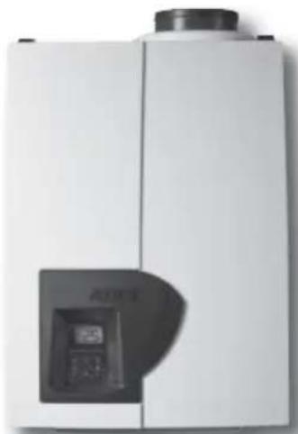
These operating instructions describe the functioning and the operating of the ATAG A boilers. This manual is for the end user. For installation and servicing there is an installation & servicing instructions manual for the installer.
Read this manual fully before operating the boiler. In case of doubt or errors contact your installer.
ATAG Heating reserves the right to change the specifications and dimensions without prior notice.

Work on the boiler must be carried out by a competent person, (Ref: Gas Safe Register) using correctly calibrated instruments with current test certification.
When replacing parts use only ATAG Service parts.
Contact details for ATAG Heating UK Ltd can be found on page 25 of this manual.
kiwa
approved product

UC WATER SUPPLY
REGULATIONS

recommended
Certification Mark
The Benchmark Scheme
ATAG Heating UK Ltd is a licensed member of the Benchmark Scheme which aims to improve the standards of installation and commissioning of domestic heating and hot water systems in the UK and to encourage regular servicing to optimise safety, efficiency and performance.
Benchmark is managed and promoted by the Heating and Hotwater Industry Council. For more information visit www.centralheating.co.uk
Please ensure that the installer has fully completed the Benchmark Checklist on the inside back pages of the installation instructions supplied with the product and that you have signed it to say that you have received a full and clear explanation of its operation. The installer is legally required to complete a commissioning checklist as a means of complying with the appropriate Building Regulations (England and Wales).
All installations must be notified to Local Area Building Control either directly or through a Competent Persons Scheme. A Building Regulations Compliance Certifi cate will then be issued to the customer who should, on receipt, write the Notification Number on the Benchmark Checklist.
This product should be serviced regularly to optimise its safety, efficiency and performance. The service engineer should complete the relevant Service Record on the Benchmark Checklist after each service.
The Benchmark Checklist may be required in the event of any warranty work and as supporting documentation relating to home improvements in the optional documents section of the Home Information Pack.“
2 Safety
Work on the installation should only be carried out by qualified personnel with calibrated equipment. When replacing parts, only ATAG Service components may be used.
If you smell gas:
- No naked flames! No smoking!
- Do not switch lights on or off or use other electrical switches.
- Do not use the phone
- Close the gas mains
- Open windows and doors
- Warn the occupants and leave the building
- Only call the gas company or installer once you are outside the building.
Corrosion protection
Do not use sprays, chlorine-containing cleaning products, solvents, paints etc. in the vicinity of the device or its air supply. These substances have an adverse impact on the device and can lead to corrosion that may result in failures.
Checking the heating water
Regularly check the water pressure of the heating installation
Always use potable water for filling the installation. Adding chemical agents such as frost and corrosion inhibitors are only to be added by your installer.
If in doubt, check with your installer or ATAG Heating UK Ltd (See contact details on page 25).
3 Boiler description

The ATAG A is a closed, condensing and modulating CH boiler with or without an integrated hot water supply which meets the European standard (CE).
A declaration of conformity can be obtained from the manufacturer.

Example SEDBUK ClassA
The efficiency of the boiler is very high and the radiation convection and standby losses very low. The emission of noxious substances is far below the fixed standards so the boiler is SEDBUK Class A rated.
4 Display and function keys

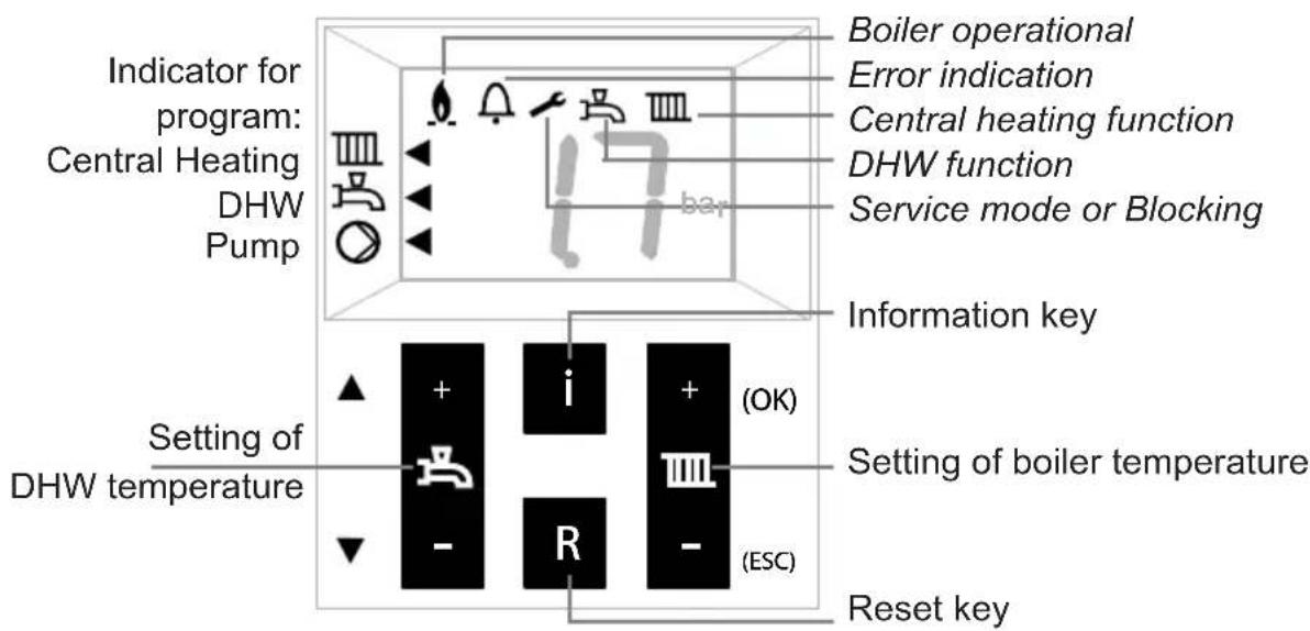
The boiler is equipped with a door at the front. After opening the door you will find a brief overview of the meaning of all the keys and icons. These are described below.
4.1 Reset-key

The reset key restarts the boiler after a malfunction has occurred.
In case of a failure the symbol 📄 is displayed with a Cx xx code. In other cases the Reset button has no function and will not respond when operated.
See 9 for a brief overview of codes.
4.2 Setting the hot water temperature

Press + or - of the 1 key;
The display will show the set value while flashing;
Press + or - to change the set value.
Each change becomes active directly.
Hot water program OFF:
Press – until the lowest value is reached and then press – again.
The display is showing -- and the upper ◀s off.
Switching on works in reverse order.
4.3 Setting the heating water temperature
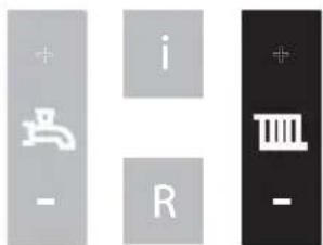
Press + or - of the Ⅲkey;
The display will show the set value while flashing;
Press + or – to change the set value.
Each change becomes active directly.
Heating program OFF:
Press – until the lowest value is reached and then press – again.
The display is showing -- and the upper ◀s off.
Switching on works in reverse order.
4.4 Requesting current data
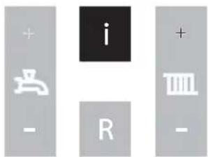
Briefly press the i-button or scroll button to obtain the following values:
A0 = Supply water temperature
A1 = Return water temperature
A2 = Hot water temperature
A4 = Flue gas temperature
(Only if a fl ue gas sensor is connected)
A5 = Outside temperature
(Only if an outside sensor is connected)
A6 = Water pressure
A9 = Rpms of fan
To return to the standard view press ESC.
5 Filling the heating installation
If you want to top up the heating installation, proceed as follows:
(If in doubt, check with your installer)
1 Connect the filling hose to the cold water tap;
2 Fill the hose completely with drinking water;
3 Connect the filled hose to the filling and draining valve of the heating installation;
4 Open the fllling and draining valve;
5 Open the cold water tap;
6 Slowly fill the CH installation to 1,5-1,7 bar:
Press the i-key until A6 appears (water pressure). The value on the display increases;
7 Close the cold water tap;
8 The code C1 05 will appear on the display the moment the pressure exceeds Venting program of approx. 7 min. becomes active;
9 Bleed the entire CH installation: start at the lowest point;
10 Check the water pressure and if necessary top off until 1.5 to 1.7 bar
11 Make sure the cold water tap and filling and draining valve are closed;
12 Disconnect the filling hose;
After the venting program (c1 05) of approx. 7 minutes has ended, the boiler will be operational again.
Check the water pressure regularly and top it up if necessary. The operating pressure in the system under cold conditions should be between 1.5 and 1.7 bar.

It may take some time before all the air has disappeared from a newly filled installation. Especially in the first week, sounds may be heard that indicate air. The automatic air vent in the boiler will let this air escape, causing the water pressure to drop during this period and water will need to be refilled again.
6 Decommissioning the boiler
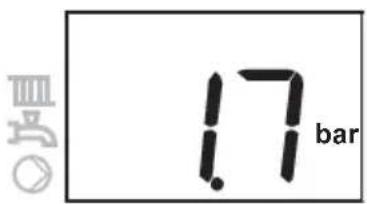
In case of, for instance, a holiday:
Heating and hot water OFF:
Press the - key of both keys until the lowest value has been reached. Release the key and press the – key once again. The display is showing --. The program has thus disabled. The arrow to the left is off.
In case of work on the heating installation:
Make sure no heat request occurs: let no hot water tap run and set the room thermostat to low. Pull the plug from the wall socket. If the installation is being drained, you have to take into account that part of the heating water will remain in the boiler. Make sure that the remaining heating water in the boiler cannot freeze in case of frost.
7 Comfort/Eco setting of hot water
The hot water supply has been preset in the factory to Comfort. This means that hot water is available instantly when you open the hot water tap. If desired, you can choose the Eco mode. This means that when tapping, it will take a little longer before hot water will flow from the hot water tap. This depends on the pipe length between the boiler and water points and the current heating temperature.
▲ scroll


OK
ESC
Changing the setting:
Press the OK key for 3 seconds.
The display is showing 'P6 (alternated with) 81';
Press the Scroll key 1x;
The display is showing 'P6 (alternated with) 84';
Press the OK key;
The display is showing 'b0';
Press the Scroll key 1x;
The display is showing 'b1';
Press the OK key;
The display is showing 'on' (= Comfort);
Adjust the value by means of the + or - key to 'off' (= Eco);
Briefly press the OK key to confirm the new setting.
The display is showing the chosen parameter again
Press the ESC key until the default display is shown again.
If during 8 minutes no key has been used, the default display is displayed on the screen automatically.
8 Pump continuous

In case of frost you are advised to have the circulation pump run continuously to reduce the chance of frozen pipes.
The pump is preset in the factory to automatic. This means that the pump is switched on when there is a request for heating or hot water. If necessary, the pump can also operate continuously. This requires the following actions:
Press the OK key for 3 seconds.
The display is showing 'P6 (alternated with) 81';
▲ scroll


OK
ESC
Press the Scroll key 1x;
The display is showing 'P6 (alternated with) 84';
Press the OK key;
The display is showing 'b0';
Press the OK key;
The display is showing 'off' (= automatic);
Adjust the value by means of the + or - key to 'on' (= continuously);
Briefly press the OK key to confirm the new setting.
The display is showing the chosen parameter again
Press the ESC key until the default display is shown again.

An arrow appears on the display in the bottom left-hand corner, indicating that the pump is now continuously switched on.
If during 8 minutes no key has been pressed, the default display is displayed on the screen automatically.
9 Errors
In the event of a failure (this is indicated by a c and number code on the display) you can try to eliminate the failure by pressing the Reset key. If the failure persists, please contact your installer as soon as possible and tell him the number code.
There are also messages with a c and a number code that constitute no failures. These messages will cancel themselves over time or after fi lling (or draining) the heating system. Operating the reset button has no effect then, for example:
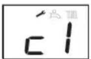
Venting program active

c1 05 venting program active (approx. 7 min.)
c1 17 water pressure too high
c1 18 water pressure too low
If leaks occur in the installation, please contact your installer.
10 Maintenance
Conclude a maintenance agreement with your installer in order to have the installation periodically checked and adjusted.
The cover of the boiler consists of plastic parts, which can be cleaned with a normal (non-aggressive) cleansing agent.
11 Warranty
For the warranty conditions, see the Warranty Card that has been delivered with the boiler.
Instrukcja obstugi

A243C
A325C
Spis treści
web: www.atag.com.pl

ATAG
- INHOUD
- CONTENTS
- IMPORTANT
- 1 INTRODUCTION
- THE BENCHMARK SCHEME
- 2 SAFETY
- IF YOU SMELL GAS
- CORROSION PROTECTION
- CHECKING THE HEATING WATER
- 3 BOILER DESCRIPTION
- 4 DISPLAY AND FUNCTION KEYS
- 4.1 RESET-KEY
- 4.2 SETTING THE HOT WATER TEMPERATURE
- 4.3 SETTING THE HEATING WATER TEMPERATURE
- 4.4 REQUESTING CURRENT DATA
- 5 FILLING THE HEATING INSTALLATION
- 6 DECOMMISSIONING THE BOILER
- IN CASE OF, FOR INSTANCE, A HOLIDAY
- IN CASE OF WORK ON THE HEATING INSTALLATION
- 7 COMFORT/ECO SETTING OF HOT WATER
- 8 PUMP CONTINUOUS
- PRESS THE OK KEY FOR 3 SECONDS
- PRESS THE SCROLL KEY 1X
- PRESS THE OK KEY
- ADJUST THE VALUE BY MEANS OF THE + OR - KEY TO 'ON' (= CONTINUOUSLY)
- BRIEFLY PRESS THE OK KEY TO CONFIRM THE NEW SETTING
- PRESS THE ESC KEY UNTIL THE DEFAULT DISPLAY IS SHOWN AGAIN
- 9 ERRORS
- 10 MAINTENANCE
- 11 WARRANTY
- INSTRUKCJA OBSTUGI
- SPIS TREŚCI
- ATAG
Brand : Atag
Model : A320S
Category : Central heating boiler