
MT10 - DJ Equipment MCINTOSH - Free user manual and instructions
Find the device manual for free MT10 MCINTOSH in PDF.


| Product Type | Turntable |
| Brand | McIntosh |
| Model | MT10 |
| Drive System | Belt drive |
| Motor | Electronic speed control |
| Tonearm Type | Gimbal-bearing tonearm |
| Speeds | 33 1/3 and 45 RPM |
| Dimensions (W x H x D) | 17.5 in (44.5 cm) x 7.0 in (17.8 cm) x 15.0 in (38.1 cm) |
| Weight | 30 lbs (13.6 kg) |
| Power Supply | 120V 60Hz or 230V 50Hz (selectable) |
| Power Consumption | 20 watts |
| Platter Material | Acrylic |
| Platter Weight | 7.5 lbs (3.4 kg) |
| Stylus | MC (moving coil) cartridge with replaceable stylus |
| Maintenance | Clean stylus with brush; replace belt every 3-5 years |
| Safety Certifications | UL, CE |
| Spare Parts Available | Stylus, belt, motor drive belt |
| Repairability | Modular design; service center recommended |
| General Information | High-end turntable for audiophile use |
Frequently Asked Questions - MT10 MCINTOSH
User questions about MT10 MCINTOSH
0 question about this device. Answer the ones you know or ask your own.
Ask a new question about this device
Download the instructions for your DJ Equipment in PDF format for free! Find your manual MT10 - MCINTOSH and take your electronic device back in hand. On this page are published all the documents necessary for the use of your device. MT10 by MCINTOSH.
USER MANUAL MT10 MCINTOSH
McIntosh Laboratory, Inc. 2 Chambers Street Binghamton, New York 13903-2699 Phone: 607-723-3512 www.mcintoshlabs.com
MT10
Precision Turntable
Owner's Manual
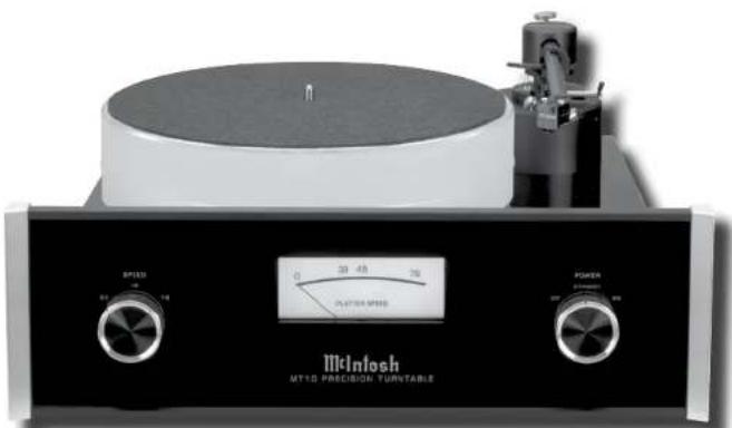
natural_image
Exterior view of a vintage McInosh MT10 Precision Turntable quartz crystal stand (no visible text or symbols on the device body)
The lightning flash with arrowhead, within an equilateral triangle, is intended to alert the user to the presence of uninsulated "dangerous voltage" within the product's enclosure that may be of sufficient magnitude to constitute a risk of electric shock to persons.
WARNING - TO REDUCE RISK OF FIRE OR ELECTRICAL SHOCK, DO NOT EXPOSE THIS EQUIPMENT TO RAIN OR MOISTURE.
IMPORTANT SAFETY INSTRUCTIONS!
PLEASE READ THEM BEFORE OPERATING THIS EQUIPMENT.
- Read these instructions.
- Keep these instructions.
- Heed all warnings.
- Follow all instructions.
- Do not use this apparatus near water.
- Clean only with a dry cloth.
- Do not block any ventilation openings. Install in accordance with the manufacturer's instructions.
- Do not install near any heat sources such as radiators, heat registers, stoves, or other apparatus (including amplifiers) that produce heat.
- Do not defeat the safety purpose of the polarized or grounding-type plug. A polarized plug has two blades with one wider than the other. A grounding type plug has two blades and a third grounding prong. The wide blade or the

AVIS RISQUE DE CHOC ELECTRIQUE - NE PAS OUVRIR. NO USER-SERVICEABLE PARTS INSIDE. REFER SERVICING TO QUALIFIED PERSONNEL.
third prong are provided for your safety. If the provided plug does not fit into your outlet, consult an electrician for replacement of the obsolete outlet.
-
Protect the power cord from being walked on or pinched particularly at plugs, convenience receptacles, and the point where they exit from the apparatus.
-
Only use attachments/accessories specified by the manufacturer.
-
Use only with the cart, stand, tripod, bracket,
or table specified by the manufacturer, or sold with the apparatus. When a cart is used, use caution when moving the cart/ apparatus combination to avoid injury from tip-over.
-
Unplug this apparatus during lightning storms or when unused for long periods of time.
-
Refer all servicing to qualified service personnel. Servicing is required when the apparatus has been damaged in any way, such as power-supply cord or plug is damaged, liquid has been spilled or objects have fallen into the apparatus, the apparatus has been exposed to

The exclamation point within an equilateral triangle is intended to alert the user to the presence of important operating and maintenance (servicing) instructions in the literature accompanying the appliance.
To prevent the risk of electric shock, do not remove cover or back. No user-serviceable parts inside.
WARNING: Use this product only with the Power Adapter provided. Failure to do so may result in fire and/or electrical shock.
rain or moisture, does not operate normally, or has been dropped.
15. Do not expose this equipment to dripping or splashing and ensure that no objects filled with liquids, such as vases, are placed on the equipment.
16. To completely disconnect this equipment from the a.c. mains, disconnect the AC / DC Adapter from the a.c. receptacle.
17. The mains plug of the power supply cord shall remain readily operable. If the AC / DC Adapter is provided with a mains power supply cord attachment, the plug of this power supply cord shall remain readily operable.
18. Do not expose batteries to excessive heat such as sunshine, fire or the like.
19. Connect mains power supply cord only to a mains socket outlet with a protective earthing connection.
Thank You
Your decision to own this McIntosh MT10 Precision Turntable and MCC10 Moving Coil Cartridge ranks you at the very top among discriminating music listeners. You now have “The Best.” The McIntosh dedication to “Quality,” is assurance that you will receive many years of musical enjoyment from this unit. Please take a short time to read the information in this manual. We want you to be as familiar as possible with all the features and functions of your new McIntosh.
Please Take A Moment
The serial number, purchase date and McIntosh Dealer name are important to you for possible insurance claim or future service. The spaces below have been provided for you to record the Turntable and Cartridge information:
| Dealer Name | Purchase Date | Model Number | Serial Number |
| MT10 | |||
| MCC10 |
Technical Assistance
If at any time you have questions about your McIntosh product, contact your McIntosh Dealer who is familiar with your McIntosh equipment and any other brands that may be part of your system. If you or your Dealer wish additional help concerning a suspected problem, you can receive technical assistance for all McIntosh products at:
McIntosh Laboratory, Inc.
2 Chambers Street
Binghamton, New York 13903
Phone: 607-723-1545
Fax: 607-724-0549
Customer Service
If it is determined that your McIntosh product is in need of repair, you can return it to your Dealer. You can also return it to the McIntosh Laboratory Service Department. For assistance on factory repair return procedure, contact the McIntosh Service Department at:
McIntosh Laboratory, Inc.
2 Chambers Street
Binghamton, New York 13903
Phone: 607-723-3515
Fax: 607-723-1917
Copyright 2009, 2010, 2014 © by McIntosh Laboratory, Inc.
Table of Contents
Safety Instructions....2
Thank You and Please Take a Moment....3
Technical Assistance and Customer Service ....3
Table of Contents ....3
General Information 4
Connector and Cable Information ....4
Introduction....5
Performance Features 5
Dimensions 6
Unpacking the Turntable....7
Assembling the Turntable....8
Installing a non-supplied Cartridge
and Tone Arm Adjustments....10
Rear Panel Connections and Adjustments....13
How to Connect the Turntable....14
Front Panel Display, Switches, Lever
and Record Clamp....16
How to Operate the Turntable.... 17
Specifications....18
Packing Instruction....19
General Information
Caution: To prevent possible damage to the turntable platter bearing, do not move the MT10 Precision Turntable with the platter installed.
- For additional connection information, refer to the owner's manual(s) for any component(s) connected to the MT10 Precision Turntable.
- The MT10 Precision Turntable comes with the McIntosh MCC10 High Performance Moving Coil Cartridge.
- It is recommended the Professionals at your McIntosh Dealer, who are skilled in all aspects of Turntables and Phono Cartridges, install the MT10 Precision Turntable and any associated audio equipment.
- For optimum performance, the setup and adjustment of the MT10 Precision Turntable requires special test recordings and test/measurement equipment. Contact your McIntosh Dealer for additional information and assistance.
- When discarding the unit, comply with local rules or regulations. Batteries should never be thrown away or incinerated but disposed of in accordance with the local regulations concerning battery disposal.
- For additional information on the MT10 and other McIntosh Products please visit the McIntosh Web Site at www.mcintosh-labs.com.
-
When an AC Line Cord is used to connect the supplied AC / DC Adapter to an AC Outlet, it is important the line cord conductor size is a minimum is 0.75mm^2 for each leg of the two conductor cord.
-
If it should become necessary to replace the supplied AC / DC Adapter and/or the plug adapters, order part number 320310SP from the McIntosh Parts Department. Refer to the illustration below.

natural_image
Product photo of a black AVIS power supply unit with attached electrical connectors (no visible text or symbols on main body)
Connector and Cable Information
Power Control Connector
The MT10 Power Control Input/Output Jacks receive/ send Power On/Off Signals when connected to other McIntosh Components. A 3.5mm stereo mini phone
plug is used for connection to the Power Control Input/Output on the MT10.
Note: The Data and Power Control Connecting Cable is available from the McIntosh Parts Department:
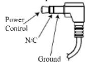
Data and Power Control Cable Part No. 170-202
Six foot, shielded 2 conductor, with 1/8 inch stereo mini phone plugs on each end.
Tonearm Headshell Wiring
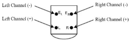
Refer to the following list of wire colors in the head-shell for installing the cartridge into the Headshell:
Cartridge Connections Headshell Wire Color
Left Channel (+) White
Left Channel (-) Blue
Right Channel (+) Red
Right Channel (-) Green
McIntosh MCC10 Cartridge Connections
Refer to the following illustration when connecting the McIntosh Cartridge in the Headshell:
Rear View of McIntosh MCC10 Cartridge
Introduction
The McIntosh MT10 Precision Turntable with the McIntosh MCC10 Moving Coil Cartridge offers the latest in playback of vinyl recordings. A full complement of performance features allows for the enjoyment of all recordings reproduced with flawless realism. The advanced electronic and mechanical design ensures many years of smooth trouble free operation.
Performance Features
• Advanced Technology Turntable
The MT10 combines the latest technology in Phono Cartridges, Tone Arms, Mechanical Suspensions and Record Platter Rotation for superb performance and accurate operation.
- Moving Coil Cartridge
The McIntosh MCC10 Moving Coil Cartridge has a hand polished ebony wood-tone body and is slightly rounded, leading to a resonance free construction. High impedance, together with high output voltage, ensures noise free musical reproduction. The ruler-flat frequency response from 20Hz to 20kHz provides solid realistic bass, uncolored midrange and natural high frequencies.
- Tone Arm
The MT10 Tone Arm is made from Dural-Aluminum with special damping material. The Tone Arm is both light in weight and highly rigid. The noise free Vertical Bearings are made from two high precision ceramic surfaces with damping fluid. The Horizontal Bearing is a gimballed sapphire design.
- Turntable Platter
The over twelve pound, two and one-half inch thick platter is made from a special silicone acrylic material. This helps to resist external vibrations from reaching the record during playback and its large mass provides the perfect flywheel action for stable playback speed.
• Precision Motor and Drive Electronics
The Swiss made DC Brushless Motor is controlled by a highly refined servo control system. As the Turntable Platter rotates, an optical sensor "reads" the 1595 micro stripes on a disk affixed to the bottom of the platter. This provides precise feedback information to the servo control system thus assuring very accurate speed rotation.
• Illuminated Speed Meter
The Illuminated Speed Meter on the MT10 indicates the true rotation speed of the turntable platter.
• Magnetic Air Dampened Bearing
The MT10 Turntable Platter rotates on a special bearing using magnetic suspension together with a cushion of air to provide vibration free rotation.
- Multi-Layered Dampened Chassis
The MT10 Turntable Chassis is composed from a Stainless Steel base plate, a thick Aluminum plate, an Acrylic plate and together with internal dampening material all help to assure the only sound heard is from the record groove itself.
- Power Control
The Power Control Input connection provides convenient Turn-On/Off of the MT10 Front Panel Illumination when connected to a McIntosh System with Power Control.
• Fiber Optic Solid State Illumination
The even Illumination of the Front Panel and the Turntable Platter is accomplished by the combination of custom designed Fiber Optic Light Diffusers and extra long life Light Emitting Diodes (LEDs).
- Glass Front Panel and Super Mirror Chassis Finish
The famous McIntosh Illuminated Glass Front Panel and the Stainless Steel Chassis with Super Mirror Finish ensure the pristine beauty of the MT10 will be retained for many years.
Dimensions
The following dimensions can assist in determining the best location for your MT10.
Front View of the MT10
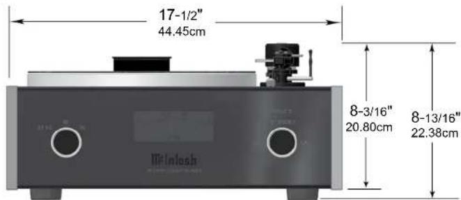
Note: The height measurements are with the McIntosh Cartridge installed.
Rear View of the MT10

Side View of the MT10

Unpacking the Turntable
To protect the fine finish of the MT10 Precision Turntable during the assembly and adjustment process, it is advisable to prepare a suitable clean working area with a soft, clean fabric, such as a bed linen or blanket.
It is recommended that the Professionals at your McIntosh Dealer, who are skilled in all aspects of installation and operation, unpack, assemble, adjust and install the MT10 Precision Turntable and any associated audio equipment.
CAUTION: To prevent possible damage to the turntable platter bearing, do not move the MT10 Precision Turntable with the platter installed.
- After opening the outer shipping carton, carefully remove the turntable inner carton (which has two foam end caps) and the turntable platter/accessory inner carton. Refer to figure 1.

- Open the turntable inner carton and remove the top foam pad. Refer to figure 2.

Figure 2
- Carefully lift up on the sides of the turntable and remove it from the turntable inner carton.
- Open the turntable platter/accessory carton and remove the the turntable platter. Refer to Figure 3

Figure 3
- Open the accessories box and check to make sure the following items are inside:
A. McIntosh MCC10 Moving Coil Cartridge.
B. AC / DC Adapter with plug adapters.
C. Tonearm Counter Weight.
D. Stylus Force Gauge.
E. Turntable Record Clamp.
F. Turntable Bubble Level.
G. Assembly/Adjustment Tools.
H. Cartridge Mounting Hardware.
1. Pair of cloth gloves.
J. Turntable Bearing Oil (full-synthetic).
K. Tone Arm Height Gauge (used for MCC10 Cartridge).
L. Protractor.
M. Cloth Dust Cover.
N. Turntable Platter Mat.
Note: The Turnable Platter Mat is located in an album cover and in the Turntable Platter/Accessory Carton.
- Proceed to Assembly of the Turntable starting on the next page.

Assembling the Turntable
Locate the McIntosh MCC10 Moving Coil Cartridge, Tools and Mounting Hardware from the Accessory Box. In the following steps the Cartridge will be installed in the Tone Arm Headshell of the Turntable. CAUTION: To prevent possible damage to the Cartridge Stylus, DO NOT remove the clear protective cover at this time.
- Using an appropriate tool, attach the four color coded wire lead connections coming from the front underside of the Tone Arm onto the rear of the McIntosh Moving Coil Cartridge as follows. Refer to figures 4, 5, 6 and 8.
Rear View of McIntosh MCC10 Cartridge

Cartridge Pin Identification
Wire Color
E
^K E_L L
Red Blue Whi
- Locate in the Hardware Package two M2.5 x 4.5mm mounting screws.
- Position the Cartridge to the underside of the Tone Arm Headshell, with the top rear edge of the Cartridge parallel to and
touching the machined ridge of the Headshell. Refer to figures 7 and 8.
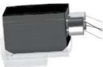
Figure 6
Figure 6
- Insert the two screws (from step 2) through the top of the headshell and into the Cartridge Body

Figure 7

Figure 8
and fasten them with a small screwdriver. Make sure the sides of the Cartridge are parallel to the sides of the Tone Arm Headshell before tightening the screws. Refer to figure 9.
-
Remove any shipping Figure 9 restraining materials from the Tone Arm Rest Holder. Refer to figure 10.
-
Remove the foil tape from the Tone Arm Support Arm to free Shipping restraint
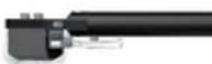
Figure 9
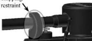
Figure 10
the Anti-Skate Cord. Refer to figure 11.
- Position the Anti-Skate Cord over the Anti-Skate Pulley. Refer to figure 12A.
- Verify the correct setting of the Anti-Skate for the McIntosh Cartridge by measur-
ing the distance as indicated in figure 12B. If the distance is not correct, first slide the "O" Ring away from the Anti-Skate Weight. Rotate the Anti-Skate Weight to set the correct dis-
tance and then slide the "O" Ring back up the Anti-Skate Weight.
- Locate the Tone Arm Counterweight. Looscn up the knurled knob to permit installing the Counterweight onto the rear of the Tone Arm. Position the Counterweight on the Tone Arm so the front surface of the Counterweight lines up with the McIntosh MCC10 Cartridge position marking on the surface. Refer to figure 13. Then tighten the knurled knob
to secure the position of the Counterweight.

Anti-Skate Pulley
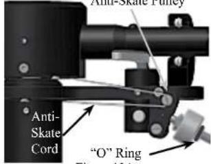
“O” Ring Figure 12A
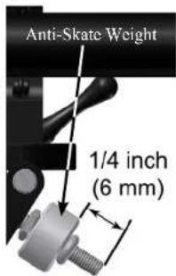
Figure 12B
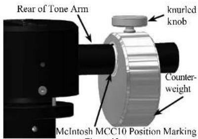
Figure 13
- Locate the Tone Arm Height Gauge (used for the McIntosh MCC10 Cartridge) from inside the accessory box.
- The gauge should just fit between the Tone Arm Housing and the Mounting Plate of the Tone Arm. This will verify the preset Tone Arm Height has not changed during shipping. Refer to figure 14. If the space has
changed, refer to page 11 for additional information on setting the Tone Arm Height.
- Place the McIntosh MT10 Turntable in its operation location.
Notes: 1. To
MCC10 Height Gauge

Figure 14
re- duce
the chance of acoustic feedback, locate the turntable the greatest possible distance from the system loudspeakers.
-
To minimize the possibility of the cartridge stylus jumping record grooves, place the turntable on a mechanically stable surface such as wall shelving anchored to wall studs.
-
Remove the protective film from the Optical Sensor located on the Turntable Top Surface. Refer to figure 15.
- Remove the protective film from the bottom of the Turntable Platter covering the Optical Ring. Refer to figure 16.
- Remove the protective film from the bottom of the Turntable Vertical Bearing opening. Refer to figure 17.
- Locate the supplied Turntable Bearing Oil and place two small drops of Oil on the top sides of the Vertical Bearing Ceramic Shaft. Refer to figure 15.
- Very carefully center the Vertical Bearing Ceramic Shaft with the Vertical Bearing opening on the bottom of the Turntable Platter. Lower the Platter onto the Ceramic Shaft while keeping the platter parallel with the top surface of the Turntable. Refer to figures 18, 19 and 20.
- Using the supplied cloth gloves, place the belt onto the circumference of the platter and then onto the pulley of the motor. Rotate the platter by hand while seating the
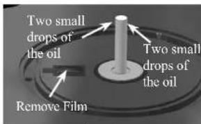
Figure 15

Figure 16

Figure 17
belt into the recessed groove on the platter.
- Locate the Tur ntable Platter Mat and place it on top of the platter.
- Locate the McIntosh Bubble Level and place it on the Tur nt able Pla- ter Mat. If the Bubble is not in the center circle of the Bubble Level, adjust the height of the Turn- table Feet (by rotating them clockwise or counter clockwise) until it is level. Refer to figure 21.
- Carefully slide off the clear protective cover from the cartridge by pulling the cover straight toward you.
- Proceed to "Rear Panel Con- nections and Adjustments" on page 13.

natural_image
Mechanical device with mounted components and a cylindrical top (no visible text or symbols)Figure 18
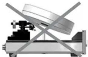
natural_image
Mechanical assembly diagram showing intersecting metal components and a central component (no text or symbols)Figure 19
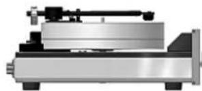
Figure 20

natural_image
Mechanical assembly diagram showing a rotating platform with mounting bracket and control panel (no text or symbols)Figure 21

Installing a non-supplied Cartridge
CAUTION: To prevent possible damage to the turntable platter bearing, do not move the MT10 Precision Turntable with the platter installed.
In the event a non-supplied Phono Cartridge is to be installed into the McIntosh MT10 Turntable please follow the steps below:
Note: It is recommended that the Professionals at your McIntosh Dealer, who are skilled in all aspects of installation and adjustment of the McIntosh MT10 Precision Turntable perform the assembly, installation and adjustments.
- When a Phono Cartridge is already installed into
the MT10 Turntable Tone Arm Head-shell, un-install it by removing the mounting screws. Refer to figure
- Then carefully disconnect the four

Figure 22
push-on wire clips from the rear of the phono cartridge. Place the removed cartridge and screws in a safe place for possible future use.
- Locate the Hardware Package supplied with the new cartridge.
- Using an appropriate tool, attach the four color coded wire lead connections coming from the front underside of the Tone Arm onto the rear of the new Phono Cartridge, following the instructions supplied with the Cartridge. Below is the
Tone Arm Headshell wire color lead identification: Wire Color
Red - Right Channel Positive (+) Signal Connection
Green - Right Channel Negative (-) Ground Connection
White - Left Channel Positive (+) Signal Connection
Blue - Left Channel Negative (-) Ground Connection
4. Position the Cartridge Spacer (supplied with the
MT10 Turntable) to the underside of the Tone Arm Headshell with the top rear edge of the Spacer parallel to and touching the machined ridge of the Headshell. Refer to figure 7 on page 8 and figure 23.
-
Position the Cartridge to the underside of the Cartridge Spacer with the sides of the Cartridge parallel to the sides of the Headshell. Secure the Phono Cartridge Body and Cartridge Spacer to the Headshell with the mounting hardware supplied with the new Phono Cartridge using the appropriate tools. Re
-
Proceed to "Tone Arm Adjustments".
Tone Arm Adjustments
Phono Cartridge/Headshell Alignment
The MT10 Turntable Tone Arm, like all pivoting Tone Arms, follows a slight arc as it transverses across the surface of a phonograph record. The Tone Arm Headshell of the MT10 Turntable allows for making adjustments (sometimes referred to as the overhang adjustment) via positioning of the Phono Cartridge relative to the Headshell. Follow the steps below using the supplied McIntosh Tone Arm/Cartridge Alignment Gauge:

Figure 23

Figure 24
- Place the Gauge over the center spindle post on the Turntable Platter and position the Gauge so the Ar-
row Tip on the gauge is pointing to the center of the Tone Arm Horizontal Pivot point. Refer to figures 25 and 26.
Note: The Top of the Tone Arm has a small circle to aid in determining the center
of the Tone Arm and is located between the letters "N" and "T" of the name McIntosh.
- Carefully place the Tone Arm onto the Alignment Gauge with the diamond tip of the stylus on the small circle located between the parallel lines. Refer to figures 27 and 28.
Note: It may be necessary to slide the Phono Cartridge forwards or backward in the headshell to position the stylus in the center of the circle.
- It is important the Front and Sides of the Phono Cartridge Body line up with these parallel lines when looking down over the top of the Tone Arm. Refer to figures 28 and

natural_image
Close-up of a white circular disc mounted on a black stand, with no visible text or symbols.Figure 25
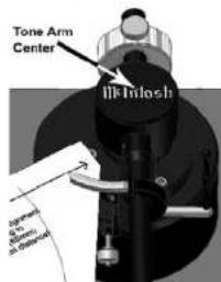
Figure 26
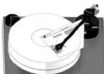
Figure 27

Figure 28
- If it is not parallel, loosen the mounting hardware securing the Phono Cartridge to the Tone Arm. Reposition the Phono Cartridge so the diamond tip of the stylus is in the center of the small circle and the
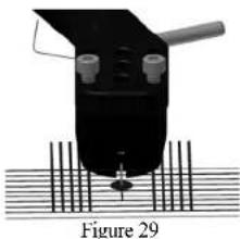
natural_image
Diagram of a mechanical device with a central component and vertical lines, labeled Figure 29 (no text or symbols on the diagram itself)Front and Sides of the Phono Cartridge are parallel to the lines on the Alignment Gauge. Tighten up the mounting hardware and verify the correct alignment.
- Set the desired tracking force pressure by using the supplied Tracking Force Gauge and adjust the position of the MT10 Tone Arm Counter Weight. Refer to page 12 "Setting the Tracking Force".
Note: Adjusting the tracking force pressure closer to the maximum setting recommend by the Phono Cartridge Manufacturer will produce better sound and less record and stylus wear than setting the tracking force pressure to the minimum setting.
Tone Arm Height
To assure the best sound reproduction, it is very important the MT10 Tone Arm is parallel to the record surface during playback. The height of the Tone Arm is adjustable to accommodate the different Phono Cartridge physical heights. To adjust for the proper Tone Arm Height, perform the following the steps:
- Release the Tone Arm from the Tone Arm Rest, place it on a record and check to see if the Tone Arm is parallel to the surface of the record. With the Tone Arm parallel, no adjustment is needed and proceed to "Trackability Adjustments". If the Tone Arm is not parallel, note whether the rear of the
Tone Arm needs to go up or down.
- With the Tone Arm secured in the Tone Arm Rest, carefully loosen the two set screws while supporting the rear of the Tone Arm. Reposition the Tone Arm based on findings in the previous step. Temporarily tighten one of the set screws. Refer to
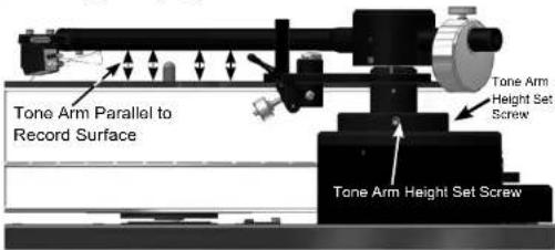
Figure 30
figure 30.
- Release the Tone Arm from the rest and place it on a record and check to see if the Tone Arm is now parallel. Also check to make sure the Tone Arm is
parallel to the record platter and the right side of the turntable base. Refer to figure 31.
- With the Tone Arm parallel to the record surface, record platter and turntable base tighten both set screws, which were loosened in step 2. If not, repeat steps 1, 2 and 3 until the Tone Arm is parallel.
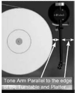
Figure 31
Tone Arm Lift Height
The MT10 Tone Arm Lift is pre-adjusted to accommodate the combined thickness of the supplied Turntable Record Mat and Phonograph Records. If a different Record Mat and/or thicker Phonograph Record are used, there may not be sufficient clearance between the Phono Cartridge Stylus and the Phonograph Record surface with the Tone Arm Lift in the cue up position. Perform the following steps to readjust the Tone Arm Lift:
-
Secure the Tone Arm in the Tone Arm Rest. Note: Before making any adjustments to the Tone Arm Lift check to see if the Tone Arm is parallel to the record surface when playing a record first. See "Tone Arm Height" section on page 11.
-
Using the appropriate tool, carefully loosen the Set Screw while supporting the bottom the Tone Arm Lift. Refer to figure 32.
-
Re-position the Tone Arm Lift Mechanism upwards slightly and then tighten the Set Screw.
-
Check the clearance between the Phono Cartridge Stylus and the Phonograph Record surface with the Tone Arm Lift in the cue up position. If necessary, re Tone Arm Lift and re-cl
-
With the Turntable stopped and no Phonograph record on the record mat, make sure the Phono Cartridge Stylus comes in contact with the record mat with the Tone Arm Lift in the down position.

Figure 32

Setting the Tracking Force
The MT10 is supplied with a Stylus Tracking Force Gauge for checking and adjusting the Stylus Tracking Force. The Gauge uses the "Balance Scale" methodology for measurement. Place the Gauge on the record
mat and perpendicular to the front of the Tone Arm, with the Stylus Tip over graduation marks. Note the current position of the Anti-Skate Adjustment and then temporarily set the Anti-Skate Adjustment to minimum. Refer to figure 33.

Figure 33
Adjust the position of the Tone Arm Counterweight to establish a tracking force in the middle of the
recommend range from the Cartridge manufacturer as a starting place. Refer to figure 34 Then position the
diamond tip of the cartridge on the Stylus Force Gauge just below the 2.5 Gram Line (setting to 2.4 Grams for the McIntosh MCC10 Phono Cartridge). Refer to figure 35. Carefully slide the Tone Arm Counterweight unitl the Gauge balances. Refer to figures 36 thru 38.

Figure 34
Note: Usually, adjusting the tracking force closer to the maximum setting recommend by the Cartridge Manufacturer will produce better sound with less record and stylus wear. Refer to "Trackability Adjustments" for additional information.
Return the Anti-Skate Weight to its previous position.

Stylus Force Scale ____ (Graduations are in grams) Figure 35

Figure 36

Figure 37
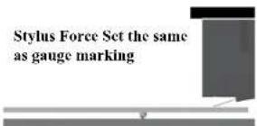
Figure 38
Trackability Adjustments
During playback of Phonograph Recordings, the Diamond tip of the stylus assembly is subjected to all kinds of extreme operating conditions. There are forces constantly trying to push the stylus out of the grooved wall of the recording. Tracking Force Pressure works to keep the stylus in contact with the groove wall. Uneven side to side pressure is applied to
the stylus as it tries to stay in contact with both sides of the groove wall. Refer to figure 39.

Figure 39
This is a function of all pivoting Tone Arms where the headshell is
usually angled inwards to minimize the playback arc. The Anti-Skating Adjustment of the MT10 Tone Arm permits equalizing for even side to side pressure.
The correct amount of Tracking Force Pressure and Anti-Skate Pressure varies with the exact shape of the Diamond Stylus Tip, Tone Arm Characteristics and finally the audio signal (both frequency and amplitude) contained in the groove wall of the record playing.
The way to achieve the best performance and the least amount of Diamond Stylus Tip/Record Groove wear is to use special test recordings, such as the Shure Trackability Test Record (TTR101). Both Tracking Force and Anti-Skate Adjustments are made as a result of listening to the specially recorded tracks and following the instructions to reduce different forms of audible distortions. While making these adjustments, do not exceed the manufacturers recommend Maximum Tracking Force Pressure Setting.
Your McIntosh Dealer, using Test Measurement Equipment and Professional Test Recordings, can achieve via adjustments, the best possible sound quality from your record collection and ensure the greatest longevity.
Rear Panel Connections and Adjustments

How to Connect the Turntable
- Connect a Power Control Cable from the MT10 POWER CONTROL REMOTE IN to the POWER CONTROL ACC Output jack of a McIntosh Pre-amplifier or A/V Control Center.
- Optionally, connect a Power Control Cable from the MT10 POWER CONTROL REMOTE OUT to the POWER CONTROL IN jack of a McIntosh source component.
- Connect a wire from the MT10 GND (Ground) Post to the GND (Ground) post on the McIntosh Preamplifier or A/V Control Center.
- Connect Audio Cables from the MT10 OUT L and R jacks to the MC (Moving Coil) Inputs on a McIntosh Preamplifier or A/V Control Center.
Note: The MT10 Turntable with the MCC10 Maying Coil Cartridge should produce a satisfactory volume level when connected to a Preamplifier or A/V Control Center with a Moving Magnet Phono Input. If additional volume level is desired, an in-line Pre-Preamplifier or step up transformer may be added. Contact your McIntosh Dealer for additional information and assistance.
- Connect the supplied AC / DC Adapter to the MT10 DC IN 24V socket and the Power Supply to a live AC outlet.

Notes

How to Operate the Turntable
Power Selection
Rotate the POWER Switch to select the Turntable operation mode desired. Refer to figure 50.
Power Off - The Front Panel and Turntable Platter lights are turned Off. There is no Turntable Platter rotation.
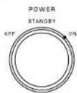
Standby - The Front Panel and Figure 50 Turntable Platter will illuminate when the McIntosh Preamplifier or A/V Control Center is turned On. There is no Turntable Platter rotation. Note: There must be a power control connection between the MT10 and the McIntosh Preamplifier or A/V Control Center, in order for the Standby Mode to function.
On - The Front Panel and Turntable Platter lights are turned On. The Turntable Platter will rotate at the selected speed.
Speed Selection
Rotate the SPEED Switch to select the playback speed (33-1/3 rpm, 45 rpm or 78 rpm) of the phonograph record to be played. Refer to figure 51.
The Front Panel Platter Speed Meter indicates the actual speed of the Turntable Platter during playback of the recording. Refer to figure 52.

Figure 51

Figure 52
Tone Arm Lift
The McIntosh MT10 Precision Turntable has a built-in manual Tone Arm Lift Mechanism for safe placement and removal of the cartridge stylus on the phonograph record. Perform the following steps:
- Push on the top part of the Tone Arm Lift Lever towards the rear of the turntable. Refer to figure 53.
Tone Arm Lift Lever

natural_image
Mechanical assembly diagram showing a rotating shaft and housing with a labeled component (no text or symbols present)Figure 53
- Release the Tone Arm from the Tone Arm Holder. Refer to figure 54.
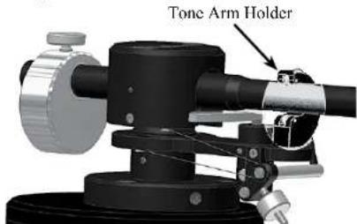
Figure 54
-
Position the Tone Arm over the desired spot of the Phonograph record.
-
Pull on the top part of the Tone Arm Lift Lever towards the front of the turntable to begin playback.
MCC10 Cartridge Specifications
Output Level
0.5 mV at 5 cm/s
Load Impedance
400 ohms recommended
Frequency Response
20Hz to 50,000Hz
Channel Separation
Greater than 30dB at 1kHz
Compliance
6 × 10^-6 ~cm/dyne
Recommended Tracking Force
2.4 g
Channel Difference
Less than 0.3 dB
Total Mass
11 g
Stylus
Elliptical Diamond
Cantilever Material
Aluminum
Coil Assembly
Symmetric design
Playback Speeds
33 1/3 rpm, 45 rpm and 78 rpm
Motor Type
DC Brushless
General SpecificationsMT10 Turntable Specifi
Overall Dimensions
Width is 17-1/2 inches (44.45cm)
Height is 8-13/16 inches (22.38cm)
Depth is 21 inches (53.34cm)
Note: Tone Arm Height will vary depending on the type of Cartridge installed.
Weight
42 pounds (19.0Kg) net, 63 pounds (28.6Kg) in shipping carton
Shipping Carton Dimensions
Width is 24 inches (61cm)
Depth is 27 inches (68.6cm)
Height is 25 inches (63.5cm)
Packing Instructions
In the event it is necessary to repack the equipment for shipment, the equipment must be packed exactly as shown below. It is very important the four feet are still attached to the bottom of the equipment. This will ensure the proper equipment location on the bottom pad. Failure to do this will result in shipping damage.
Use the original shipping carton and interior parts only if they are all in good serviceable condition. If a shipping carton or any of the interior part(s) are needed, please call or write Customer Service Department of McIntosh Laboratory. Refer to page 3. Please refer to the Part List below for the correct part numbers.
Quantity Part Number Description
1 034420 Outer shipping carton only
1 034424 Turntable Platter/Accessories
Inner carton only
2 034425 Top and bottom foam pad
1 034426 Center foam pad
1 034427 Accessory box
1 034421 Turntable Inner carton only
1 034422 Turntable Top foam pad
1 034419 Bottom locating pad
2 034423 End caps

flowchart
graph TD
    A["Top foam pad"] --> B["Turntable Platter"]
    C["Center foam pad"] --> D["Turntable Platter/Accessories Inner Carton"]
    E["Bottom foam pad"] --> D
    B --> F["Accessory box"]
    D --> F
    F --> G["Inner carton containing Turntable Platter/Accessories"]
    G --> H["Outer shipping carton containing platter/accessories inner carton and turntable inner carton"]
    H --> I["Inner carton containing Turntable without Platter"]
    I --> J["Turntable Inner Carton with foot locating pad (pad is inside the carton on the bottom)"]
    J --> K["Turntable Top foam pad"]
    K --> L["Turntable without Platter"]
    L --> M["Turntable Inner Carton with foot locating pad (pad is inside the carton on the bottom)"]
    M --> N["Turntable Top foam pad"]

McIntosh Laboratory, Inc.
2 Chambers Street
Binghamton, NY 13903
www.mcintoshlabs.com
The continuous improvement of its products is the policy of McIntosh Laboratory Incorporated who reserve the right to improve design without notice. Printed in the U.S.A.
- WARNING - TO REDUCE RISK OF FIRE OR ELECTRICAL SHOCK, DO NOT EXPOSE THIS EQUIPMENT TO RAIN OR MOISTURE.
- IMPORTANT SAFETY INSTRUCTIONS!
- PLEASE READ THEM BEFORE OPERATING THIS EQUIPMENT.
- AVIS RISQUE DE CHOC ELECTRIQUE - NE PAS OUVRIR. NO USER-SERVICEABLE PARTS INSIDE. REFER SERVICING TO QUALIFIED PERSONNEL.
- To prevent the risk of electric shock, do not remove cover or back. No user-serviceable parts inside.
- WARNING: Use this product only with the Power Adapter provided. Failure to do so may result in fire and/or electrical shock.
- Thank You
- Please Take A Moment
- Technical Assistance
- Customer Service
- Table of Contents
- General Information
- Connector and Cable Information
- Power Control Connector
- Tonearm Headshell Wiring
- McIntosh MCC10 Cartridge Connections
- Introduction
- Performance Features
- • Advanced Technology Turntable
- - Moving Coil Cartridge
- - Tone Arm
- - Turntable Platter
- • Precision Motor and Drive Electronics
- • Illuminated Speed Meter
- • Magnetic Air Dampened Bearing
- - Multi-Layered Dampened Chassis
- - Power Control
- • Fiber Optic Solid State Illumination
- - Glass Front Panel and Super Mirror Chassis Finish
- Dimensions
- Unpacking the Turntable
- Assembling the Turntable
- Installing a non-supplied Cartridge
- Tone Arm Adjustments
- Phono Cartridge/Headshell Alignment
- Tone Arm Height
- Tone Arm Lift Height
- Setting the Tracking Force
- Trackability Adjustments
- Rear Panel Connections and Adjustments
- How to Connect the Turntable
- How to Operate the Turntable
- Power Selection
- Speed Selection
- Tone Arm Lift
- MCC10 Cartridge Specifications
- General SpecificationsMT10 Turntable Specifi
- Packing Instructions
- Quantity Part Number Description
Brand : MCINTOSH
Model : MT10
Category : DJ Equipment