AOC-STGN-I2S - Network card Supermicro - Free user manual and instructions
Find the device manual for free AOC-STGN-I2S Supermicro in PDF.


| Product Type | 10 Gigabit Ethernet Network Adapter |
| Model | AOC-STGN-I2S |
| Form Factor | Standard Low-Profile PCI Express Add-on Card |
| Controller | Intel 82599ES 10GbE Controller |
| Ports | 2 SFP+ Ports (10Gbps/1Gbps) |
| Bus Interface | PCI Express 2.0 x8 (5 GT/s) |
| Dimensions (PCB) | 10.16 cm x 6.90 cm (4.00 in x 2.73 in) |
| Weight | Approx. 200 g (0.44 lb) |
| Power Consumption | 11.2 W (typical) |
| Operating Temperature | 0°C to 55°C (32°F to 131°F) |
| Compliance | RoHS Compliant 6/6, Pb Free |
| Virtualization Features | VMDq, Next-Gen VMDq (64 queues/port), SR-IOV |
| Manageability | PXE Boot, iSCSI Remote Boot, NC-SI (Rev. 2.10 or newer) |
| Supported Cables | DAC Twin Axial (up to 7m) and LC Fiber-Optic (with optional transceiver) |
| OS Support | Windows Server 2003-2012, Windows 7/8/Vista, Linux, FreeBSD, VMware |
| LED Indicators | Link (Green/Yellow for 10Gb/1Gb) and Activity (Blinking Green) |
| Care and Maintenance | Handle by edges; use antistatic precautions; clean with dry cloth; avoid liquids |
| Safety Warnings | ESD sensitive; contains lead solder (handle with care) |
| Spare Parts / Repairability | Not user-serviceable; optional transceivers and cables available |
| Warranty | Standard manufacturer warranty; contact vendor for RMA |
| Intended Use | For Supermicro server systems/motherboards with PCIe x8 slot |
Frequently Asked Questions - AOC-STGN-I2S Supermicro
src directory, and run make install. Load the module with modprobe ixgbe. Detailed instructions are in the manual.User questions about AOC-STGN-I2S Supermicro
0 question about this device. Answer the ones you know or ask your own.
Ask a new question about this device
Download the instructions for your Network card in PDF format for free! Find your manual AOC-STGN-I2S - Supermicro and take your electronic device back in hand. On this page are published all the documents necessary for the use of your device. AOC-STGN-I2S by Supermicro.
USER MANUAL AOC-STGN-I2S Supermicro
natural_image
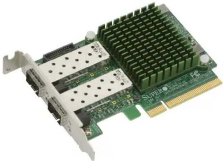
Close-up of a green printed circuit board (PCB) with visible cooling fins and ports, no text or symbols present.AOC-STGN-i2S
natural_image
Close-up of a green Super GPU card with dual Ethernet ports and a grid-patterned top (no visible text or symbols)User's Guide
Revision 1.0c
The information in this User's Guide has been carefully reviewed and is believed to be accurate. The vendor assumes no responsibility for any inaccuracies that may be contained in this document, and makes no commitment to update or to keep current the information in this user's guide, or to notify any person or organization of the updates. Please Note: For the most up-to-date version of this user's guide, please see our Website at www.supermicro.com.
Super Micro Computer, Inc. ("Supermicro") reserves the right to make changes to the product described in this user's guide at any time and without notice. This product, including software and documentation, is the property of Supermicro and/or its licensors, and is supplied only under a license. Any use or reproduction of this product is not allowed, except as expressly permitted by the terms of said license.
IN NO EVENT WILL SUPER MICRO COMPUTER, INC. BE LIABLE FOR DIRECT, INDIRECT, SPECIAL, INCIDENTAL, SPECULATIVE OR CONSEQUENTIAL DAMAGES ARISING FROM THE USE OR INABILITY TO USE THIS PRODUCT OR DOCUMENTATION, EVEN IF ADVISED OF THE POSSIBILITY OF SUCH DAMAGES. IN PARTICULAR, SUPER MICRO COMPUTER, INC. SHALL NOT HAVE LIABILITY FOR ANY HARDWARE, SOFTWARE, OR DATA STORED OR USED WITH THE PRODUCT, INCLUDING THE COSTS OF REPAIRING, REPLACING, INTEGRATING, INSTALLING OR RECOVERING SUCH HARDWARE, SOFTWARE, OR DATA.
Any disputes arising between the manufacturer and the customer shall be governed by the laws of Santa Clara County in the State of California, USA. The State of California, County of Santa Clara shall be the exclusive venue for the resolution of any such disputes. Supermicro's total liability for all claims will not exceed the price paid for the hardware product.
FCC Statement: This equipment has been tested and found to comply with the limits for a Class A digital device pursuant to Part 15 of the FCC Rules. These limits are designed to provide reasonable protection against harmful interference when the equipment is operated in a commercial environment. This equipment generates, uses, and can radiate radio frequency energy and, if not installed and used in accordance with the manufacturer's instruction manual, may cause harmful interference with radio communications. Operation of this equipment in a residential area is likely to cause harmful interference, in which case you will be required to correct the interference at your own expense.
California Best Management Practices Regulations for Perchlorate Materials: This Perchlorate warning applies only to products containing CR (Manganese Dioxide) Lithium coin cells. "Perchlorate Material-special handling may apply. See www.dtsc.ca.gov/hazardouswaste/perchlorate".
WARNING: Handling of lead solder materials used in this product may expose you to lead, a chemical known to the State of California to cause birth defects and other reproductive harm.
User's Guide Revision 1.0c
Release Date: September 23, 2015
Unless you request and receive written permission from Super Micro Computer, Inc., you may not copy any part of this document.
Information in this document is subject to change without notice. Other products and companies referred to herein are trademarks or registered trademarks of their respective companies or mark holders.
Copyright © 2015 by Super Micro Computer, Inc.
All rights reserved.
Printed in the United States of America
Preface
About this User's Guide
This user's guide is written for system integrators, IT technicians and knowledgeable end users. It provides information for the installation and use of the AOC-STGN-i1S/-i2S add-on module.
About this Add-on Module
The AOC-STGN-i1S/-i2S 10-Gigabit Ethernet Adapter is the most flexible and scalable Ethernet adapter for today's demanding data center environments. Based on the Intel® 10GbE network controller 82599, the AOC-STGN-i1S/-i2S meets the demanding needs of the next-generation data center by providing features for virtualization, flexibility for LAN and SAN networking, and proven reliable performance.
An Important Note to the User
All images and layouts shown in this user's guide are based upon the latest PCB Revision available at the time of publishing. The card you have received may or may not look exactly the same as the graphics shown in this user's guide.
Returning Merchandise for Service
A receipt or copy of your invoice marked with the date of purchase is required before any warranty service will be rendered. You can obtain service by calling your vendor for a Returned Merchandise Authorization (RMA) number. When returning the motherboard to the manufacturer, the RMA number should be prominently displayed on the outside of the shipping carton, and the shipping package is mailed prepaid or hand-carried. Shipping and handling charges will be applied for all orders that must be mailed when service is complete. For faster service, You can also request a RMA authorization online (http://www.supermicro.com/RmaForm/).
The manufacturer warranty only covers normal consumer use and does not cover damages incurred in shipping or from failure due to the alternation, misuse, abuse or improper maintenance of products.
During the warranty period, contact your distributor first for any product problems.
Conventions Used in the User's Guide
Pay special attention to the following symbols for proper system installation and for safety instructions to prevent damage to the system or injury to yourself:

Warning: Important information given to ensure proper system installation or to prevent damage to the components or injury to yourself.

Note: Additional information given for proper system setup.
Naming Convention
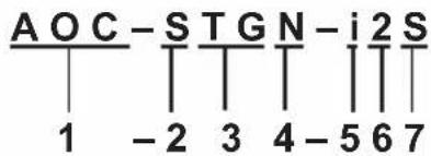
| Character Representation Options | ||
| 1st Product | Family AOC: Add On Card | |
| 2nd Form Factor S: Standard, P: Proprietary, C: MicroLP, U: UIO | ||
| 3rd | Product Type/Speed | G: GbE (1Gb/s), TG: 10GbE (10Gb/s), 40G: 40GbE (40Gb/s), IBF: FDR IB (56Gb/s), IBQ: QDR IB (40Gb/s) |
| 4th | Chipset Model (Optional) | N: Niantec (82599), P: Powerville (i350), S: Sageville (X550) |
| 5th Chipset | Manufacturer i: Intel, m: Mellanox, b: Broadcom | |
| 6th Number | of Ports 1: 1 port, 2: 2 ports, 4: 4 ports | |
| 7th | Connector Type (Optional) | S: SFP+, T: 10GBase-T, Q: QSFP+ |
SMC Networking Add-on Cards
| Model | Type | Form Factor | Interface | Controller | Connection | Dimension (w/o Brackets) (L x H) | Power (W) |
| SGP-i2 | GbE | Standard LP | PCI-E x4 | Intel® i350 AM2 | 2 RJ45 (1Gb/port) | 3.9" (9.9cm) x 2.73" (6.9cm) | 3.5 |
| SGP-i4 | GbE | Standard LP | PCI-E x4 | Intel® i350 AM4 | 4 RJ45 (1Gb/port) | 3.9" (9.9cm) x 2.73" (6.9cm) | 5 |
| STG-b4S | 10GbE | Standard LP | PCI-E x8 | Broadcom® BCM57840S | 4 SFP+ (10Gb/port) | 5.4" (13.7cm) x 2.73" (6.9cm) | 14 |
| STG-i2T | 10GbE | Standard LP | PCI-E x8 | Intel® X540 2 RJ45 (10Gb/port) | 5.9" (14.99cm) x 2.73" (6.9cm) | 13 | |
| STGN-i2S | 10GbE | Standard LP | PCI-E x8 | Intel® 82599ES | 2 SFP+ (10Gb/port) | 4.0" (10.2cm) x 2.73" (6.9cm) | 11.2 |
| STGN-i1S | 10GbE | Standard LP | PCI-E x8 | Intel® 82598EN | 1 SFP+ (10Gb/port) | 4.0" (10.2cm) x 2.73" (6.9cm) | 10 |
| STG-i4S | 10GbE | Standard LP | PCI-E x8 | Intel® XL710-AM1 | 4 SFP+ (10Gb/port) | 5.9" (14.9cm) x 2.73" (6.9cm) | 8 |
| S40G-i2Q | 40GbE | Standard LP | PCI-E x8 | Intel® XL710 AM2 | 2 QSFP+ (40Gb/port) | 5.9" (14.9cm) x 2.73" (6.9cm) | 7 |
| PG-i2+ | GbE | Proprietary | PCI-E x4 | Intel® 82576EB | 2 RJ45 (1Gb/port) | 3.78" (9.6cm) x 2.44" (6.2cm) | 3 |
| PTG-i1S | 10GbE | Proprietary | PCI-E x8 | Intel® 82599EN | 1 SFP+ (10Gb/port) | 10.04" (25.5cm) x .78" (2.0cm) | 7.5 |
| UG-i4 | GbE | UIO FH | PCI-E x8 | Intel® 82571EB | 4 RJ45 (1Gb/port) | 6.6" (16.7cm) x 3.9" (9.8cm) | 10 |
| CGP-i2 | GbE | MicroLP | PCI-E x4 | Intel® i350 AM2 | 2 RJ45 (1Gb/port) | 4.45" (11.3cm) x 1.54" (3.9cm) | 4 |
| CG-i2 | GbE | MicroLP | PCI-E x4 | Intel® 82580 | 2 RJ45 (1Gb/port) | 4.45" (11.3cm) x 1.3" (3.4cm) | 4 |
| CIBF-m1 | FDR IB | MicroLP | PCI-E x8 | Mellanox® ConnectX-3 | 1 QSFP (56Gb/port) | 4.85" (12.3cm) x 1.54" (3.9cm) | 7 |
| CIBQ-m1 | QDR IB | MicroLP | PCI-E x8 | Mellanox® ConnectX-3 | 1 QSFP (40Gb/port) | 4.85" (12.3cm) x 1.54" (3.9cm) | 7 |
| CTG-i1S | 10GbE | MicroLP | PCI-E x8 | Intel® 82599EN | 1 SFP+ (10Gb/port) | 4.85" (12.3cm) x 1.54" (3.9cm) | 10 |
| CTG-i2S | 10GbE | MicroLP | PCI-E x8 | Intel® 82599ES | 2 SFP+ (10Gb/port) | 4.85" (12.3cm) x 1.54" (3.9cm) | 11 |
| CTG-i2T | 10GbE | MicroLP | PCI-E x8 | Intel® X540 | 2 RJ45 (10Gb/port) | 4.8" (12.3cm) x 2.75" (7.7cm) | 13 |
| CTGS-i2T | 10GbE | MicroLP | PCI-E x4 | Intel® X550 | 2 RJ45 (10Gb/port) | 4.45" (11.3cm) x 1.54" (3.9cm) | 12 |
Contacting Supermicro
Headquarters
Address: Super Micro Computer, Inc.
980 Rock Ave.
San Jose, CA 95131 U.S.A.
Tel: +1 (408) 503-8000
Fax: +1 (408) 503-8008
Email: marketing@supermicro.com (General Information)
support@supermicro.com (Technical Support)
Website: www.supermicro.com
Europe
Address: Super Micro Computer B.V.
's-Hertogenbosch, The Netherlands
Tel: +31 (0) 73-6400390
Fax: +31 (0) 73-6416525
Email: sales@supermicro.nl (General Information)
support@supermicro.nl (Technical Support)
rma@supermicro.nl (Customer Support)
Website: www.supermicro.nl
Asia-Pacific
Address: Super Micro Computer, Inc.
3F, No. 150, Jian 1st Rd.
Zhonghe Dist., New Taipei City 235
Taiwan (R.O.C)
Tel: +886-(2) 8226-3990
Fax: +886-(2) 8226-3992
Email: support@supermicro.com.tw
Website: www.supermicro.com.tw
Table of Contents
Preface
Chapter 1 Overview
1-1 Overview 1-1
1-2 Product Highlights.... 1-1
1-3 Technical Specifications.... 1-2
General....1-2
I/O Features 1-2
Virtualization Features.... 1-2
Manageability Features.... 1-3
OS Support 1-3
Cable Support 1-4
Operation Conditions 1-4
Physical Dimensions 1-4
Optional Accessories 1-4
Compliance/Environmental 1-5
1-4 SMC Platform Support 1-5
Chapter 2 Hardware Components
2-1 Add-On Card Image and Layout.... 2-1
2-2 Major Components....2-3
2-3 Connectors and LAN LED Indicators.... 2-4
LAN Ports 2-4
LAN LED 2-4
NC-SI Connector 2-5
Chapter 3 Installation
3-1 Static-Sensitive Devices.... 3-1
Precautions 3-1
Unpacking 3-1
3-2 Before Installation 3-2
3-3 Installing the Add-on Card 3-2
3-4 Installing Drivers on Windows.... 3-3
3-5 Installing Drivers on Linux.... 3-3
Build a Binary RPM Package....3-3
3-6 Installing Drivers on FreeBSD 3-5
Chapter 1
Overview
1-1 Overview
Congratulations on purchasing your add-on card from an acknowledged leader in the industry. Supermicro products are designed with the utmost attention to detail to provide you with the highest standards in quality and performance. For product support and updates, please refer to our website at http://www.supermicro.com/products/nfo/networking.cfm#adapter.
1-2 Product Highlights
The product highlights of this add-on card include the following:
• Single/Dual SFP+ Connector
- Standard Low-profile
• PCI Express 2.0 (up to 5GT/s)
Intel® QuickData Technology
- VMDq, Next-Generation VMDq, and PC-SIG SR-IOV for Virtualized Environments
- Load Balancing on Multiple CPUs
• iSCSI Remote Boot Support
• Fibre Channel over Ethernet (FCoE) Support
• Support for most Network Operating Systems (NOSs)
• Support both DAC Twin Axial and LC Fiber-Optic Cables
• Network Controller Sideband Interface (NC-SI) (Rev. 2.10 or newer)
• RoHS compliant 6/6

1-3 Technical Specifications
General
- Intel® 82599EN 10GbE controller (AOC-STGN-i1S) / Intel 82599ES 10GbE controller (AOC-STGN-i2S)
• Standard low-profile form factor
• Single SFP+ port (AOC-STGN-i1S)
• Dual SFP+ ports (AOC-STGN-i2S)
• PCI-E 2.0 x8 (5GT/s) - Load balancing on multiple CPUs
• iSCSI remote boot support
• Fibre Channel over Ethernet (FCoE) Support
Intel® PROSet Utility for Windows® Device Manager
I/O Features
- Intel® QuickData Technology: DMA engine that enhances data acceleration and lowers CPU usage
- Direct Cache Access (DCA) to avoid cache misses
- MSI-X support to minimize the overhead of interrupts allowing load-balancing between multiple cores/CPUs
• Tx/Rx IP, SCTP, TCP and UDP checksum offloading capabilities (IPv4, IPv6) - Receive and Transmit Side Scaling for Windows environments and Scalable I/O for Linux environments
Virtualization Features
- Supports virtualization features such as VMDq, Next-generation VMDq (64 queues per port) and PC-SIG SR-IOV implementation
- IPv6 Offloading
• Advanced Packet Filtering
• VLAN support to allow creation of multiple VLAN segments
• VXLAN through Software
Manageability Features
• Preboot eXecution Environment (PXE) support
• Simple Network Management Protocol (SNMP) and Remote
• Network Monitoring (RMON) statistics counters
- iSCSI remote boot
- NC-SI for remote management (Only supported with Supermicro motherboards with corresponding NC-SI connectors)
OS Support
- Windows® Server 2012 (x64 edition)
- Windows® 8 (x64 edition and 32-bit)
- Windows® Server 2008 R2 (x64 edition and 64-bit)
- Windows® Server 2008 (x64 edition, 64-bit, and 32-bit)
- Windows® 7 (x64 edition and 32-bit)
- Windows® Vista (x64 edition and 32-bit)
- Windows® Server 2003 (x64 edition, 64-bit, and 32-bit)
VMWare
• RedHat EL, SuSe SLES - FreeBSD
Cable Support
- SFP+ direct attached twin axial cables, up to 7 meters
• LC-LC fiber-optic cables (optional SFP+ transceiver is required)
• NC-SI cable (included with the motherboard)
Operation Conditions
• Operating temperature: 0°C to 55°C
Physical Dimensions
- Card PCB dimensions (without end brackets): 10.16cm (4.00in) x 6.90cm (2.73in) (LxW)
• Height of end brackets: standard - 12cm (4.725in), low-profile - 7.94cm (3.13in)
Optional Accessories
• CBL-0347L: 1m 10GbE SFP+ to SFP+, Passive 30AWG, Pull Type
• CBL-NTWK-0347: 1m 10GbE SFP+ to SFP+, Passive 30AWG, Push Type
• CBL-NTWK-0456: 2m 10GbE SFP+ to SFP+, Passive 30AWG, Push Type
• CBL-0348L: 3m 10GbE SFP+ to SFP+, Passive 24AWG, Pull Release
• CBL-0349L: 5m 10GbE SFP+ to SFP+, Passive 24AWG, Pull Release
• CBL-SFP+AOC-1M: 1m 10GbE SFP+ to SFP+, Fiber Active Optical Cable (AOC)
• CBL-SFP+AOC-3M: 3m 10GbE SFP+ to SFP+, Fiber Active Optical Cable (AOC)
• CBL-SFP+AOC-5M: 5m 10GbE SFP+ to SFP+, Fiber Active Optical Cable (AOC)
- AOC-E10GSFPSR: SFP+ transceiver module for short range fiber cables (up to 300M), 10G/1G, 850nm, MMF, LC
- AOC-E10GSFPLR: SFP+ transceiver module for long range fiber cables (up to 10km), 10G/1G, 1310nm, MMF, LC
- AOC-TSR-FS: SFP+ transceiver module for short range fiber cables (up to 300m), 10G/1G, 850nm, MMF, LC
- AOM-TSFP-709DMZ-AVG: SFP+ transceiver module for short range fiber cables, 10G/1G, 850nm, MMF, LC
Compliance/Environmental
• RoHS Compliant 6/6, Pb Free

1-4 SMC Platform Support
The following platforms are supported by the AOC-STGN-i1S and AOC-STGN-i2S add-on cards:
• Supermicro motherboards with minimum PCI-E x8 slot
• Supermicro servers with full-height or low-profile PCI-E x8 expansion slot
- NC-SI feature is only supported by Supermicro motherboards with corresponding NC-SI connectors
Note: This product is intended to be used with Supermicro server systems or motherboards as an integrated solution package.
For the most current product information, visit: www.supermicro.com
Notes
Chapter 2
Hardware Components
2-1 Add-On Card Image and Layout
natural_image
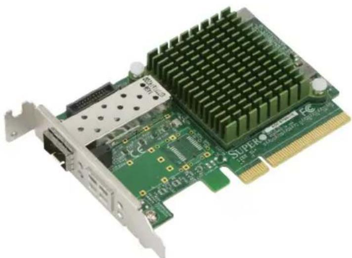
Close-up of a green PCI card with heat sink and network ports (no visible text or symbols)The AOC-STGN-i1S Image
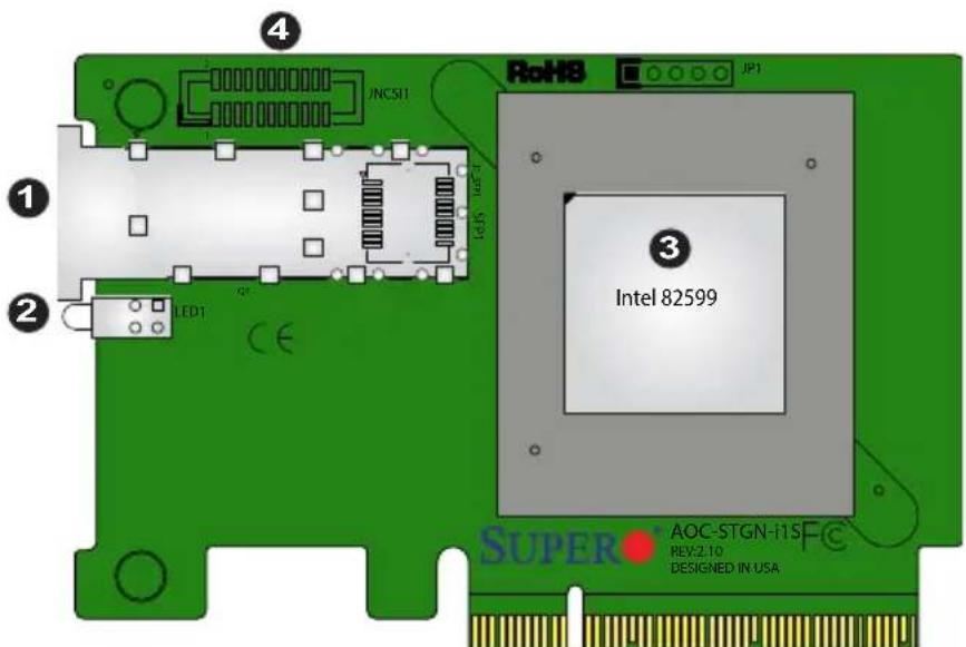
The AOC-STGN-i1S Layout
| Components | |
| Number Description | |
| 1 SFP+ | Port |
| 2 LED1 | |
| 3 Intel 8 | 2599 Network Controller |
| 4 NC-SI | Connector |
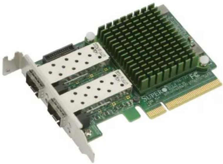
natural_image
Close-up of a green super-resolution computer motherboard with dual ports and a grid-patterned top (no visible text or symbols)The AOC-STGN-i2S Image
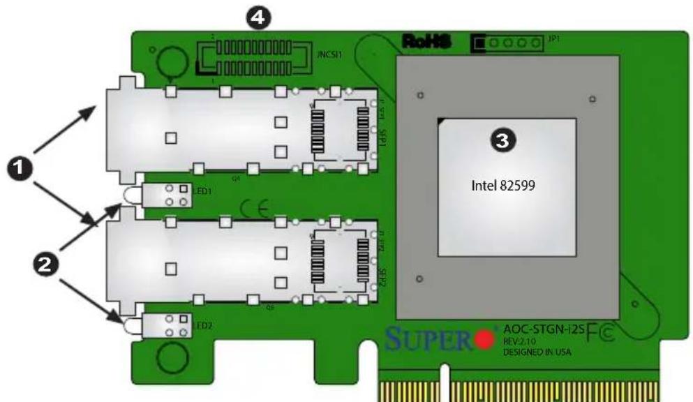
The AOC-STGN-i2S Layout
| Components | |
| Number Description | |
| 1 SFP+ | Port1 and Port2 |
| 2 LED1 | and LED2 |
| 3 Intel 82599 | Network Controller |
| 4 NC-SI | Connector |
2-2 Major Components
The following major components are on the AOC-STGN-i1S and AOC-STGN-i2S:
- Single SFP+ port (AOC-STGN-i1S), Dual SFP+ ports (AOC-STGN-i2S)
- LED1 (AOC-STGN-i1S), LED1 and LED2 (AOC-STGN-i2S)
- Intel® 82599 LAN Controller
- NC-SI Connector
2-3 Connectors and LAN LED Indicators
LAN Ports
The AOC-STGN-i1S has one network LAN (SFP+) port, and the AOC-STGN-i2S has two. These LAN ports support connection speeds of 10Gbps and 1Gbps. Plug the Direct Attached Copper (DAC) cable into the SFP+ port for network connections.
Note 1: To make sure that LAN port functions properly, be sure to use the following cable specified by the manufacturer:
• Direct-attached twin-axial copper cable, or
- Short Range or Long Range fiber optic cable used in conjunction with optional optical transceiver.
Note 2: For detailed information on the cable and transceiver recommended by the manufacturer, please refer to "Optional Accessories" on Page 1-4 or SMC product information posted online.
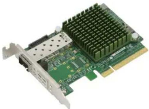
natural_image
Close-up of a green PCI card with cooling fins and ports, no visible text or symbolsThe AOC-STGN-i1S
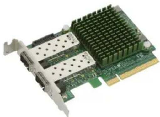
natural_image
Close-up of a green PCI card with dual ports and a heatsink (no visible text or symbols)The AOC-STGN-i2S
| LED Color Definition | ||
| LNK | Green 10Gb Link Speed | |
| Yellow 1Gb Link Speed | ||
| ACT Blinking Green Activity | ||
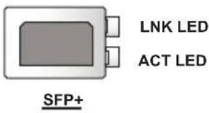
LAN LED
Each SFP+ connector has two LEDs. The LED on the top indicates link speeds, and the LED on the bottom indicates the status of activity of the connector. See the table above for more information.
NC-SI Connector
Use the NC-SI connector at JNCSI tor remote management. It is only supported with Supermicro motherboards with a corresponding NC-SI connector. The NC-SI cable is included with the motherboard. Refer to the table below for the pin definition. See the layouts on pages 2-1 and 2-2 for the location of the connector.

Note: The NC-SI connector is only available on AOC-STGN-i1S and AOC-STGN-i2S rev. 2.10.
| NC-SI ConnectorPin Definitions | |||
| Pin# Definition Pin# Definition | |||
| 1 NCSI_CLK_IN 2 GND | |||
| 3 NCSI_CRS_DV 4 GND | |||
| 5 NCSI_RXD_0 6 GND | |||
| 7 NCSI_RXD_1 8 GND | |||
| 9 NCSI_TXD_0 10 GND | |||
| 11 NCSI_TXD_1 12 GND | |||
| 13 NCSI_TX_EN 14 PRESET_N | |||
| 15 NCSI_ARB_IN 16 NCSI_ARB_OUT | |||
| 17 P5V_AUX 18 P5V_AUX | |||
| 19 P5V_AUX 20 P5V_AUX | |||
| 21 GND | 22 TP3 | ||
Notes
Chapter 3
Installation
3-1 Static-Sensitive Devices
Electrostatic Discharge (ESD) can damage electronic components. To avoid damaging your add-on card, it is important to handle it very carefully. The following measures are generally sufficient to protect your equipment from ESD.
Precautions
- Use a grounded wrist strap designed to prevent static discharge.
- Touch a grounded metal object before removing the add-on card from the antistatic bag.
- Handle the add-on card by its edges only; do not touch its components, or peripheral chips.
- Put the add-on card back into the antistatic bags when not in use.
- For grounding purposes, make sure that your system chassis provides excellent conductivity between the power supply, the case, the mounting fasteners and the add-on card.
Unpacking
The add-on card is shipped in antistatic packaging to avoid static damage. When unpacking your component or your system, make sure that you are static protected.

Note: To avoid damaging your components and to ensure proper installation, be sure to always connect the power cord last, and always remove it before adding, removing or changing any hardware components.
3-2 Before Installation
To install the add-on card properly, be sure to follow the instructions below.
- Power down the system.
- Remove the power cord from the wall socket.
- Use industry-standard anti-static equipment (such as gloves or wrist strap) and follow the precautions on Page 3-1 to avoid damage caused by ESD.
- Familiarize yourself with the server, motherboard, and/or chassis documentation.
- Confirm that your operating system includes the latest updates and hotfixes.
3-3 Installing the Add-on Card
Follow the steps below to install the add-on card into your system.
- Remove the server cover and, if necessary, set aside any screws for later use.
- Remove the add-on card slot cover. If the case requires a screw, place the screw aside for later use.
- Position the add-on card in the slot directly over the connector, and gently push down on both sides of the card until it slides into the PCI connector.
- Secure the add-on card to the chassis. If required, use the screw that you previously removed.
- Attach any necessary external cables to the add-on card.
- Replace the chassis cover.
- Plug the power cord into the wall socket, and power up the system.
- Replace the chassis cover.

Note: This add-on card is designed to support the standard low-profile PCI-Express form factor; however, it may not fit in your chassis due to the physical dimensions of the card.
3-4 Installing Drivers on Windows
Follow the steps below to install the drivers for Windows. Download the drivers from the Supermicro FTP site at ftp://ftp.supermicro.com/Networking_Drivers/.
- Run the CDR-NIC.
- When the SUPERMICRO window appears, click on the computer icon next to the product model.
![SUPERMICRO Add-On Card Drivers and Tools (Win7) SUPERMICRO® Drivers & Tools Intel 10GbE Adopters UTG-i2, STG-i2, STGN-i2S, STG-i2T, CTG-i1S, CTG-i2S IB Adopters UINF-m2, UIBG-m1, UIBG-m2, RTUG-iBQ, OBF-m1, OBB-m1, UIBF-m1 [IB drivers] IB Adopters UINF-m2, UIBG-m1, UIBG-m2, RTUG-iBQ, OBF-m1, OBB-m1, UIBF-m1 [Ethernet drivers] Intel 1GbE Adopters UG-i4, PG-i2+, SG-i2, SG-i4, SGP-i4, CGP-i2, SGP-i2, CGi2 Broadcom 10GbE Adapters STG-b4S Read Product Description and Manual For more information, please visit SUPERMICRO's web site. SUPERMICRO Computer Inc.](/content/2026/05/920558/images/96cada41e3be4722e3c5ab26edf5ed318fd0572349705e878b933cfccf42e7bd.jpg)
Note: If the FOUND NEW HARDWARE WIZARD screen displays on your system, click CANCEL.
- Click on INSTALL DRIVERS AND SOFTWARE.
- Follow the prompts to complete the installation.
3-5 Installing Drivers on Linux
Follow the steps below to install the driver for Linux.
Build a Binary RPM Package
- Run 'rpmbuild -tb
' - Replace
with the specific filename of the driver.
Note: For the build to work properly, the current running kernel MUST match the version and configuration of the installed kernel sources. If you have just recompiled the kernel, reboot the system at this time.
Follow the instructions below to build the driver manually.
- Move the base driver tar file to the directory of your choice. For example
/home/username/ixgbe
or
/usr/local/src/ixgbe
- Untar/unzip archive, where
is the version number for the driver tar file:
tar zxf ixgbe-x.x.x.tar.gz
- Change to the driver src directory, where
is the version number for the driver tar:
cd ixgbe-x.x.x/src/
- Compile the driver module:
make install
The binary will be installed as:
/lib/modules/[KERNEL_VERSION]/kernel/drivers/net/ixgbe/ixgbe.[k]o
The install locations listed above are the default locations. They might not be correct for certain Linux distributions. For more information, see the Idistrib.txt file included in the driver tar.

Note: IXGBE_NO_LRO is a compile time flag. The user can enable it at compile time to remove support for LRO from the driver. The flag is used by adding CFLAGS_EXTRA=-"DIXGBE_NO_LRO" to the make file when it's being compiled.
make CFLAGS_EXTRA="-DIXGBE_NO_LRO" install
- Load the module:
For kernel 2.6.x, use the modprobe command:
modprobe ixgbe <parameter>=<value>
For 2.6 kernels, the insmod command can be used if the full path to the driver module is specified. For example:
insmod /lib/modules/<KERNEL VERSION>/kernel/drivers/net/ixgbe/ixgbe.ko
In addition, when using 2.6-based kernels, make sure that older ixgbe drivers are removed from the kernel before loading the new module. To do this, use:
rmmod ixgbe; modprobe ixgbe
- Assign an IP address to the interface by entering the following, where x is the interface number:
ifconfig ethx
- Verify that the interface works. Enter the following, where
ping
3-6 Installing Drivers on FreeBSD
Follow the instructions below to install the drivers in FreeBSD kernel 4.8 or later. In the instructions below, x.x.x is the driver version as indicated in the name of the drive tar file.

Note: You must have kernel sources installed in order to compile the driver module.
-
Move the base driver tar file to the directory of your choice. For example, use /home/username/ixgb or /usr/local/src/ixgb.
-
Untar/unzip the archive:
tar xfz ixgb-x.x.x directory
- To install man page:
cd ixgb-x.x.x gzip -c ixgb.4 > /usr/share/man/man4/ixgb.4.gz
- To load the driver onto a running system, perform the following steps:
cd ixgb-x.x.x make or cd ixgb-x.x.x/src make load
- To assign an IP address to the interface, enter the following:
ifconfig ixgb<interface_num> <IP_address>
- Verify that the interface works. Enter the following, where
ping <IP_address>
- If you want the driver to load automatically when the system is booted:
cd ixgb-x.x.x/src
make load
cp if_ixgb.ko /modules
Edit /boot/loader.conf, and add the following line:
if_ixgb_load="YES"
or
compile the driver into the kernel (see item 8). Edit /etc/rc.conf, and create the appropriate ifconfig_ixgb
ifconfig_ixgb<interface_num>="<ifconfig_settings>"
Example usage:
ifconfig_ixgb0="inet 192.168.10.1 netmask 255.255.255.0"
- If you want to compile the driver into the kernel, enter:
cd ixgb-x.x.x/src
mkdir /usr/src/sys/dev/ixgb
cp if_ixgb* /usr/src/sys/dev/ixgb
cp ixgb* /usr/src/sys/dev/ixgb
cp Makefile.kernel /usr/src/sys/modules/ixgb/Makefile
Edit the /usr/src/sys/conf/files.i386 file, and add the following line:
dev/ixgb/ixgb_hw.c optional ixgb
dev/ixgb/ixgb_ee.c optional ixgb
dev/ixgb/if_ixgb.c optional ixgb
Remove the following lines from the /usr/src/sys/conf/files.i386 file, if they exist:
/dev/ixgb/if_ixgb_fx_hw.c optional ixgb
/dev/ixgb/if_ixgb_phy.c optional ixgb
Edit the kernel configuration file (i.e., GENERIC or MYKERNEL) in /usr/src/sys/i386/conf, and ensure the following line is present:
device ixgb
Compile and install the kernel. Reboot the system for the kernel updates to take affect.
Notes
(Disclaimer Continued)
The products sold by Supermicro are not intended for and will not be used in life support systems, medical equipment, nuclear facilities or systems, aircraft, aircraft devices, aircraft/emergency communication devices or other critical systems whose failure to perform be reasonably expected to result in significant injury or loss of life or catastrophic property damage. Accordingly, Supermicro disclaims any and all liability, and should buyer use or sell such products for use in such ultra-hazardous applications, it does so entirely at its own risk. Furthermore, buyer agrees to fully indemnify, defend and hold Supermicro harmless for and against any and all claims, demands, actions, litigation, and proceedings of any kind arising out of or related to such ultra-hazardous use or sale.
- Preface
- About this User's Guide
- About this Add-on Module
- An Important Note to the User
- Returning Merchandise for Service
- Conventions Used in the User's Guide
- Naming Convention
- SMC Networking Add-on Cards
- Contacting Supermicro
- Headquarters
- Europe
- Asia-Pacific
- Table of Contents
- Chapter 1 Overview
- Chapter 2 Hardware Components
- Chapter 3 Installation
- Chapter 1
- Overview
- 1-1 Overview
- 1-2 Product Highlights
- 1-3 Technical Specifications
- General
- I/O Features
- Virtualization Features
- Manageability Features
- OS Support
- Cable Support
- Operation Conditions
- Physical Dimensions
- Optional Accessories
- Compliance/Environmental
- 1-4 SMC Platform Support
- Notes
- Chapter 2
- Hardware Components
- 2-1 Add-On Card Image and Layout
- 2-2 Major Components
- 2-3 Connectors and LAN LED Indicators
- LAN Ports
- LAN LED
- NC-SI Connector
- Chapter 3
- Installation
- 3-1 Static-Sensitive Devices
- Precautions
- Unpacking
- 3-2 Before Installation
- 3-3 Installing the Add-on Card
- 3-4 Installing Drivers on Windows
- 3-5 Installing Drivers on Linux
- Build a Binary RPM Package
- 3-6 Installing Drivers on FreeBSD
- (Disclaimer Continued)
Brand : Supermicro
Model : AOC-STGN-I2S
Category : Network card