AOC-IBH-XDS - Network card Supermicro - Free user manual and instructions
Find the device manual for free AOC-IBH-XDS Supermicro in PDF.


| Product Type | Network Interface Card (NIC) |
| Model | AOC-IBH-XDS |
| Brand | Supermicro |
| Form Factor | Low-profile PCIe 3.0 x8 |
| Port Configuration | Dual 10GbE SFP+ |
| Data Transfer Rate | 10 Gbps per port |
| Connector Type | SFP+ (for use with copper or fiber modules) |
| Supported Standards | IEEE 802.3ae, 802.3x, 802.3ad, 802.1Q |
| Operating Temperature | 0°C to 55°C (32°F to 131°F) |
| Storage Temperature | -40°C to 70°C (-40°F to 158°F) |
| Humidity | 10% to 90% non-condensing |
| Power Consumption | 15 W (typical) |
| Power Source | PCIe bus power (3.3V and 12V) |
| Dimensions (L x H) | 13.0 cm x 6.9 cm (5.1 in x 2.7 in) |
| Weight | 100 g (3.5 oz) |
| Main Functions | High-speed data communication, network segmentation, virtualization offload (VXLAN, NVGRE), load balancing, failover |
| Compatible Operating Systems | Windows Server, Linux (RHEL, Ubuntu, CentOS), VMware ESXi, FreeBSD |
| Maintenance and Cleaning | Power off system before cleaning. Use compressed air to remove dust. Do not use liquid cleaners. |
| Safety Precautions | Anti-static handling required. Disconnect power before installation. Avoid contact with sharp components. |
| Spare Parts and Repairability | Field replaceable SFP+ modules. Card is non-serviceable; replace entire unit if defective. |
| General Information | Supermicro AOC series, designed for data centers and enterprise environments. Supports PXE boot, iSCSI, and FCoE. |
Frequently Asked Questions - AOC-IBH-XDS Supermicro
User questions about AOC-IBH-XDS Supermicro
0 question about this device. Answer the ones you know or ask your own.
Ask a new question about this device
Download the instructions for your Network card in PDF format for free! Find your manual AOC-IBH-XDS - Supermicro and take your electronic device back in hand. On this page are published all the documents necessary for the use of your device. AOC-IBH-XDS by Supermicro.
USER MANUAL AOC-IBH-XDS Supermicro
natural_image
Front view of a network switch device with ports and connectors (no visible text or labels)SBM-GEM-X2C+ 1/10 Gbps Ethernet Switch Module
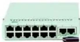
natural_image
Front view of a network switch device with multiple ports (no visible text or labels)SBM-GEM-002 Gbps Ethernet Pass-Through Module
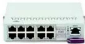
natural_image
Front view of a network switch device with multiple Ethernet ports and a purple connector (no visible text or symbols)SBM-GEM-001 Gbps Ethernet Switch Module
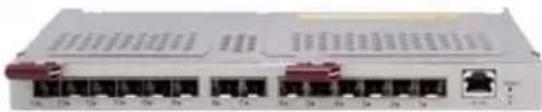
natural_image
Front view of a network switch device with multiple ports and connectors (no visible text or labels)SBM-XEM-002 10Gbps Ethernet Pass-Through Module

natural_image
Front view of a network switch device with multiple ports and indicator lights (no visible text or labels)SBM-IBS-Q3616/Q3616M/Q3618 4x QDR InfiniBand Switch Module

natural_image
Front view of a network switch device with multiple ports and connectors (no visible text or labels)SBM-IBS-001 4x DDR InfiniBand Switch Module

natural_image
Front view of a network switch unit with multiple ports and indicator lights (no visible text or labels)SBM-GEP-TCO 1 Gbps Ethernet Pass-Through Module for TwinBlade™

natural_image
Front view of a network switch device with multiple ports and ventilation grilles (no visible text or labels)SBM-IBP-D14 4x DDR InfiniBand Pass-Through Module
User's Manual
Revision 1.0d
The information in this User's Manual has been carefully reviewed and is believed to be accurate. The vendor assumes no responsibility for any inaccuracies that may be contained in this document, makes no commitment to update or to keep current the information in this manual, or to notify any person or organization of the updates. Please Note: For the most up-to-date version of this manual, please see our web site at www.supermicro.com.
Super Micro Computer, Inc. ("Supermicro") reserves the right to make changes to the product described in this manual at any time and without notice. This product, including software and documentation, is the property of Supermicro and/or its licensors, and is supplied only under a license. Any use or reproduction of this product is not allowed, except as expressly permitted by the terms of said license.
IN NO EVENT WILL SUPERMICRO BE LIABLE FOR DIRECT, INDIRECT, SPECIAL, INCIDENTAL, SPECULATIVE OR CONSEQUENTIAL DAMAGES ARISING FROM THE USE OR INABILITY TO USE THIS PRODUCT OR DOCUMENTATION, EVEN IF ADVISED OF THE POSSIBILITY OF SUCH DAMAGES. IN PARTICULAR, SUPERMICRO SHALL NOT HAVE LIABILITY FOR ANY HARDWARE, SOFTWARE, OR DATA STORED OR USED WITH THE PRODUCT, INCLUDING THE COSTS OF REPAIRING, REPLACING, INTEGRATING, INSTALLING OR RECOVERING SUCH HARDWARE, SOFTWARE, OR DATA.
Any disputes arising between manufacturer and customer shall be governed by the laws of Santa Clara County in the State of California, USA.. The State of California, County of Santa Clara shall be the exclusive venue for the resolution of any such disputes. Super Micro's total liability for all claims will not exceed the price paid for the hardware product.
FCC Statement: This equipment has been tested and found to comply with the limits for a Class A digital device pursuant to Part 15 of the FCC Rules. These limits are designed to provide reasonable protection against harmful interference when the equipment is operated in a commercial environment. This equipment generates, uses, and can radiate radio frequency energy and, if not installed and used in accordance with the manufacturer's instruction manual, may cause harmful interference with radio communications. Operation of this equipment in a residential area is likely to cause harmful interference, in which case you will be required to correct the interference at your own expense.
California Best Management Practices Regulations for Perchlorate Materials: This Perchlorate warning applies only to products containing CR (Manganese Dioxide) Lithium coin cells. Perchlorate Material-special handling may apply. See www.dtsc.ca.gov/hazardouswaste/perchlorate for further details.

WARNING: HANDLING OF LEAD SOLDER MATERIALS USED IN THIS PRODUCT MAY EXPOSE YOU TO LEAD, A CHEMICAL KNOWN TO THE STATE OF CALIFORNIA TO CAUSE BIRTH DEFECTS AND OTHER REPRODUCTIVE HARM.
Manual Revision 1.0d
Release Date: September 23, 2010
Unless you request and receive written permission from Super Micro Computer, Inc., you may not copy any part of this document.
Information in this document is subject to change without notice. Other products and companies referred to herein are trademarks or registered trademarks of their respective companies or mark holders.
Copyright © 2010 by Super Micro Computer, Inc.
All rights reserved.
Printed in the United States of America
Table of Contents
Chapter 1 Introduction....1-1
1-1 Overview....1-1
1-2 Product Checklist of Typical Components....1-1
1-3 Features.... 1-1
1-4 Contacting Supermicro....1-2
Chapter 2 System Safety....2-1
2-1 Electrical Safety Precautions....2-1
2-2 General Safety Precautions....2-2
2-3 Electrostatic Discharge Precautions 2-2
2-4 Operating Precautions....2-2
Chapter 3 Setup and Installation....3-1
3-1 Installing/Removing a Switch Module....3-1
Installing a Switch Module 3-1
Removing a Switch Module 3-3
3-2 Configuring the Switch Module 3-4
Web-based Management Utility/IPMI 3-5
Network Connection....3-5
Address Defaults....3-7
Command Line....3-8
3-3 SBM-GEM-X2C/+ 1/10 Gigabit Ethernet Switch Firmware .....3-9
Firmware Upgrading Procedures....3-9
Firmware Failure Recovery Steps....3-12
Chapter 4 InfiniBand Modules ...... 4-1
4-1 Overview....4-1
4-2 SBM-IBS-001 4X DDR InfiniBand Switch Module....4-2
4-3 SBM-IBS-Q3618/Q3616 4X QDR InfiniBand Switch Module ....4-3
4-4 SBM-IBS-Q3616M 4X QDR InfiniBand Switch Module ....4-4
4-5 SBM-IBP-D14 InfiniBand Pass-Through Module....4-6
4-6 Installation and Configuration of InfiniBand Switch Modules ....4-6 Installing/Removing the InfiniBand Switch Module ....4-6 Installing/Removing the InfiniBand Pass-Through Module ....4-7 InfiniBand Switch LEDs....4-8
Blade Software for Access to InfiniBand Switch Module 4-8
Chapter 5 Ethernet Modules ....5-1
5-1 SBM-GEM-001 Gigabit Ethernet Switch Module ....5-1
LED Indicators 5-2
Ports....5-2
5-2 SBM-GEM-X2C 1/10 Gb Ethernet Switch Module....5-3
LED Indicators 5-4
Ports....5-4
5-3 SBM-GEM-002 1Gb Ethernet Pass-through Module ....5-5
5-4 SBM-XEM-002/SBM-XEM-002M 10 Gb Ethernet Pass-through Module ....5-6
5-5 SBM-GEP-T20 1Gb Ethernet Pass-through Module for Twin-Blade Modules ....5-8
Chapter 6 1-Gb Ethernet Switch Firmware ......6-1
6-1 SBM-GEM-001 Firmware Features and Functions ......6-1
6-1 Port Status....6-4
Port VLAN ID (PVID)....6-5
Jumbo Frames Support....6-5
Port Configuration....6-5
6-2 Statistics....6-7 Port Statistics....6-7
6-3 VLAN 6-10
6-4 Configuring a Static VLAN 6-12
6-5 Trunking....6-13
6-6 Mirroring....6-15
6-7 Quality of Service....6-16 Priority Queues....6-16
6-8 Rate Control....6-18
6-9 L2 Management....6-19
6-10 Spanning Tree ....6-21
Bridge Protocol Data Unit (BPDU) ....6-21
Port Transition State....6-22
RSTP Port Roles......6-22
Root Status....6-24
Bridge Setting....6-24
RSTP Port Settings....6-25
6-11 IEEE 802.1x 6-26
Wiring for 802.1x....6-26
802.1x Configuration....6-27
6-12 IGMP Snooping....6-28
6-13 SNMP 6-30
6-14 UpLink Failure Tracking (ULFT) 6-31
Chapter 7 1/10-Gb Ethernet Switch Firmware....7-1
7-1 Overview....7-1
Nomenclature....7-2
7-2 Login....7-2
7-3 Home Page 7-3
Top Page Links 7-6
Top LED Display 7-6
Left Side Tree....7-6
Middle Configuration Link Table....7-7
7-4 System Management Page 7-7
System Settings....7-9
System Settings....7-9
System Version....7-11
File Management 7-12
Save Configuration....7-12
File Copy....7-13
File Management 7-13
Firmware Upgrade 7-14
Management Security....7-15
Management Security Basic Settings 7-15
Management User Account....7-16
Radius....7-17
TACACS+ Global Settings 7-18
TACACS+ Server Configuration....7-19
IP Authorized Manager 7-20
SSH Configuration 7-21
SSLConfiguration....7-22
Syslog 7-24
Syslog Configuration....7-24
Syslog Mail Configuration 7-25
ACL....7-26
MAC Based ACL....7-26
IP Standard ACL 7-27
IP Extended ACL....7-28
WEBGUI Settings 7-30
SNMP....7-31
SNMP Community Settings....7-32
SNMP Group Settings....7-33
SNMP Group Access Settings 7-34
SNMP View Tree Settings....7-35
SNMP Target Address Settings....7-36
SNMP Target Parameter Settings....7-37
SNMP User Settings 7-38
SNMP Trap Settings 7-39
SNMP AgentX....7-40
RMON....7-42
RMON Basic Settings 7-42
Event Configuration....7-43
RMON Alarm Configuration 7-44
Ethernet Statistics Configuration....7-45
History Control Configuration....7-46
QoS....7-47
QOS Basic Settings 7-47
QOS Classmap Settings 7-48
QOS Policymap Settings....7-49
COSQ Scheduling Algorithm....7-50
COSQ Weight and Bandwidth Configuration 7-51
NTP Settings....7-52
Stack 7-53
CX4 Cable Length....7-54
Enabling Stacking 7-55
Stack Configuration....7-58
Stack Details 7-59
Stack Link Status....7-60
Stack Counters....7-61
Reload....7-62
7-5 Layer 2 Management....7-63
Layer 2 Basic Settings ....7-64
Port Manager 7-65
Port Basic Settings....7-65
Port Monitoring....7-67
VLAN Traffic Class....7-68
Port Control....7-69
Rate Limiting 7-70
VLAN....7-71
VLAN Basic Settings....7-71
Port Settings....7-72
Static VLAN....7-73
Protocol Group....7-74
Port Protocol 7-74
Vlan Port MAC Map 7-75
Unicast MAC....7-76
Wildcard....7-77
Switch Port VLAN....7-78
Dynamic Vlan....7-79
Dynamic VLAN Global Configuration....7-79
Port Configuration....7-80
GARP Timers....7-81
RSTP 7-82
RSTP Global Settings....7-82
RSTP Basic Settings....7-83
Port Settings....7-84
Port Status....7-85
MSTP 7-86
MSTP Basic Settings 7-86
MSTP Timers 7-88
Port Configuration....7-89
VLAN Mapping....7-90
Port Settings....7-91
CIST Port Status 7-92
LA....7-94
LA Basic Settings....7-94
Interface Settings....7-95
Port Channel 7-96
Port Settings....7-97
Port State Info 7-98
Load Balancing 7-99
802.1x 7-100
Basic Settings 7-100
Port Settings....7-101
Timers 7-103
Local AS....7-104
MAC Session Info 7-105
Filters 7-106
Unicast Filters 7-106
Multicast Filters 7-107
7-6 Layer 3 Management....7-108
IP....7-109
Vlan Interface....7-109
IP V4 Interface Settings 7-110
IP Route....7-111
LoopBack Basic Settings 7-112
IP V6 7-113
IPv6 Route Configuration....7-113
IPv6 Interface....7-114
ND Cache....7-115
Address Settings....7-116
Address Profile....7-117
Prefix Settings....7-118
DHCP Server 7-119
DHCP Basic Settings 7-119
Pool Settings....7-120
DHCP Relay....7-121
DHCP Relay Basic Settings....7-121
Interface Settings....7-122
RIP....7-123
RIP Basic Settings 7-123
Interfaces 7-124
Neighbors List....7-125
Security Settings....7-126
Address Summarization....7-127
RIPng....7-128
RIP6 Interface....7-128
Filters 7-129
OSPF 7-131
OSPF Basic Settings....7-131
Area....7-132
Interface....7-133
Virtual Interface....7-134
OSPF Neighbor....7-135
OSPF RRD Route Configuration....7-136
OSPF Area Aggregation 7-137
External Aggregation....7-138
OSPF V3....7-140
OSPFv3 Basic Settings....7-140
Interface....7-141
Area....7-143
OSPF V3 External Aggregation 7-144
BGP 7-146
BGP Basic Settings....7-146
BGP Peer Configuration....7-147
BGP MED Configuration....7-148
Local Preference....7-149
BGP Filter....7-151
Route Aggregations 7-152
Advanced BGP Configuration....7-153
BGP Community Management 7-154
RRD 7-155
RRD Basic Settings....7-156
BGP....7-157
RIP....7-158
OSPF 7-159
RRD6 7-160
RRD6 Basic Settings....7-160
Filters 7-161
RRD V6 OSPF 7-162
RRD RIP 7-163
VRRP....7-164
VRRP Basic Settings 7-164
VRRP Settings....7-165
7-7 Multicast....7-166
GMP Snooping....7-166
IGMP Snooping Configuration 7-167
IGMP Snooping Timer....7-168
IGMP Snooping Interface....7-169
IGMP Snooping VLAN Router....7-170
IGMP MAC Forwarding....7-171
Dynamic Multicast....7-172
Global Configuration 7-172
Dynamic Multicast Port Configuration....7-173
IGMP....7-174
Basic Settings 7-174
Interface Configuration....7-175
Group Information 7-176
Source Information....7-177
PIM....7-178
Basic Settings 7-178
Component....7-179
Interfaces 7-180
Candidate RPs....7-181
Threshold....7-182
Static RP 7-183
DVMRP....7-184
DVMRP Basic Settings 7-184
Interfaces 7-185
7-8 Statistics....7-186
Interface....7-187
Interface Statistics....7-187
Ethernet Statistics 7-188
Radius....7-190
TACACS+ Statistics 7-192
RMON Ethernet Statistics 7-194
SNMP Statistics 7-196
Agent....7-196
SNMP AgentX....7-197
VLAN....7-198
Current DB....7-199
VLAN Port Statistics....7-200
VLAN Multicast Table....7-201
VLAN Counter Statistics....7-202
VLAN Capabilities 7-203
VLAN FDB Entries 7-204
RSTP Statistics 7-205
RSTP Information....7-205
RSTP Port Statistics....7-206
MSTP Statistics....7-208
MSTP Information....7-208
MSTP CIST Statistics....7-209
MSTP MSTI Port Statistics....7-210
LA Port Statistics....7-212
LA Neighbor Statistics....7-213
802.1X....7-214
802.1X Session Statistics....7-214
802.1X Supplicant Statistics....7-215
Mac Session Statistics 7-216
IP....7-218
ARP Cache 7-218
ICMP Statistics....7-219
IPv6....7-221
IP V6 Interface Statistics....7-221
ICMP V6 Statistics....7-223
RIP Statistics....7-225
RIP6....7-226
RIP6 Interface Statistics....7-226
RIP6 Route Information....7-227
OSPF 7-229
OSPF Route Information....7-229
OSPF Link State DB....7-230
OSPFv3 7-232
OSPFV3 Route Information 7-232
OSPFV3 Link State DB 7-233
VRRP Statistics....7-234
IGMP Snooping....7-236
IGMP Snooping Clear Statistics....7-236
IGMP Snooping V1/V2 Statistics....7-237
IGMP Snooping V3 Statistics 7-238
IGMP Statistics....7-239
PIM....7-241
PIM Interface Statistics....7-241
PIM Neighbor Statistics....7-242
PIM BSR Info 7-243
PIM RP Set Information 7-244
PIM Route Information 7-245
DVMRP....7-246
DVMRP Routers....7-246
DVMRP Multicast Routers 7-247
DVMRP Prune Statistics 7-248
Appendix A HCA Mezzanine Cards ......A-1
A-1 Safety Guidelines....A-1
ESD Safety Guidelines ......A-1
General Safety Guidelines....A-1
A-2 Mezzanine HCA Cards ......A-2
AOC-IBH-001 Mezzanine HCA Card....A-2
AOC-IBH-002 Mezzanine HCA Card....A-3
AOC-IBH-003 Mezzanine HCA Card....A-4
AOC-IBH-XDS Mezzanine HCA Card....A-5
AOC-IBH-XDD Mezzanine HCA Card ......A-6
AOC-IBH-XQS Mezzanine HCA Card ......A-7
AOC-IBH-XQD Mezzanine HCA Card ......A-8
A-3 Installation....A-9
Installation Location ......A-10
Card Installation....A-10
Appendix B LED Descriptions....B-1
B-1 Gigabit Ethernet Module LED Descriptions.....B-1
B-2 1/10 Gigabit Ethernet Module LED Descriptions......B-2
B-3 SBM-IBS-001 InfiniBand Switch LED Descriptions......B-3
B-4 SBM-IBS-Q3616/M InfiniBand Switch LED Descriptions......B-4
Appendix C Installing Triple Wide Bays ...... C-1
C-1 Installing a Triple Wide Module Bay ...... C-1
List of Figures
Figure 3-1. Blade Enclosure with 1-Gbps Switch Modules Installed....3-2
Figure 3-2. Blade Enclosure with 1/10 Gbps Switch Modules Installed....3-3
Figure 3-3. Configuring the Switch Module....3-4
Figure 3-4. IPMI Login Screen 3-5
Figure 3-5. IPMI Blade System Screen....3-6
Figure 3-6. Gigabit Switch Panel....3-7
Figure 3-7. Displayed Text for Rebooting ....3-10
Figure 3-8. Setting Hardware Information....3-11
Figure 4-1. SBM-IBS-001 InfiniBand Switch Module 4-2
Figure 4-2. SBM-IBS-Q3618/Q3616 InfiniBand Switch Module....4-3
Figure 4-3. SBM-IBS-Q3616M InfiniBand Switch Module....4-4
Figure 4-4. SBM-IBP-D14 InfiniBand Pass-Through Triple-Wide Module .....4-6
Figure 5-1. SBM-GEM-001 Gigabit Ethernet Switch Module....5-1
Figure 5-2. SBM-GEM-X2C 1/10 Gigabit Ethernet Switch Module Ports and Indicators 5-3
Figure 5-3. SBM-GEM-002 Gigabit Pass-through Module....5-5
Figure 5-4. SBM-XEM-002 10-Gigabit Pass-through Module....5-7
Figure 5-5. SBM-GEP-T20 Gigabit Pass-through Module 5-8
Figure 5-6. SBM-GEP-T20 Installed in Enclosure....5-9
Figure 6-1. Switch Status Screen....6-2
Figure 6-2. Switch System Management Screen....6-2
Figure 6-3. Port Status Screen....6-4
Figure 6-4. Jumbo Frame Setting Screen....6-5
Figure 6-5. Port Configuration Screen 6-6
Figure 6-6. Statistics Screen....6-7
Figure 6-7. Port Statistics Screen 6-8
Figure 6-8. VLAN Screen....6-10
Figure 6-9. Creating a New VLAN....6-12
Figure 6-10. New VLAN Screen....6-13
Figure 6-11. Trunking Screen 6-14
Figure 6-12. Port Mirroring Screen....6-15
Figure 6-13. QoS Setting Screen....6-17
Figure 6-14. Rate Limit and Storm Control Screen....6-18
Figure 6-15. Storm Control Screen....6-19
Figure 6-16. L2 Management Screen 6-20
Figure 6-17. L2 Management: Current Entries Screen 6-20
Figure 6-18. Rapid Spanning Tree Screen 6-23
Figure 6-19. Rapid Spanning Tree Port Settings 6-25
Figure 6-20. 802.1x Configuration Screen 6-27
Figure 6-21. IGMP Snooping Screen....6-29
Figure 6-22. Uplink Failure Tracking Configuration Screen 6-32
Figure 7-1. Login Page....7-2
Figure 7-2. Home Page....7-3
Figure 7-3. SBM-GEM-X2C/+ Home Page 7-4
Figure 7-4. SSE-G24-TG4 Home Page 7-5
Figure 7-5. SSE-G48-TG4 Home Page 7-5
Figure 7-6. System Management Page 7-7
Figure 7-7. System Settings Page 7-9
Figure 7-8. System Version Page....7-11
Figure 7-9. File Management Page....7-12
Figure 7-10. Firmware Upgrade Page....7-14
Figure 7-11. Management Security Basic Settings Page....7-15
Figure 7-12. Management User Account Page....7-16
Figure 7-13. Radius Server Configuration Page 7-17
Figure 7-14. TACACS+ Global Settings Page 7-18
Figure 7-15. TACACS+ Server Configuration Page....7-19
Figure 7-16. IP Authorized Manager Page....7-20
Figure 7-17. SSH Configuration....7-21
Figure 7-18. SSL Configuraiton Page 7-22
Figure 7-19. Syslog Configuration Page....7-24
Figure 7-20. Syslog Mail Configuration Page....7-25
Figure 7-21. MAC ACL Configuration Page....7-26
Figure 7-22. IP Standard ACL Configuration Page....7-27
Figure 7-23. IP Extended ACL Page....7-28
Figure 7-24. Web GUI Settings Page....7-30
Figure 7-25. SNMP Agent Control Settings Page....7-31
Figure 7-26. SNMP Community Settings Page....7-32
Figure 7-27. SNMP Group Settings Page....7-33
Figure 7-28. SNMP Group Access Settings Page ......7-34
Figure 7-29. SNMP View Tree Settings Page....7-35
Figure 7-30. SNMP Target Address Settings Page 7-36
Figure 7-31. SNMP Target Parameter Settings Page....7-37
Figure 7-32. SNMP Security Settings Page....7-38
Figure 7-33. SNMP Trap Settings Page....7-39
Figure 7-34. SNMP AgentX Subagent Settings Page....7-40
Figure 7-35. RMON Basic Settings Page....7-42
Figure 7-36. Event Configuration Settings Page....7-43
Figure 7-37. RMON Alarm Configuration Page....7-44
Figure 7-38. Ethernet Statistics Configuration Page....7-45
Figure 7-39. History Control Configuration Page....7-46
Figure 7-40. QOS Basic Settings Page....7-47
Figure 7-41. QOS Classmap Settings Page 7-48
Figure 7-42. QOS Policymap Settings Page....7-49
Figure 7-43. COSQ Scheduling Algorithm Settings Page....7-50
Figure 7-44. COSQ Weight and Bandwidth Configurations Page....7-51
Figure 7-45. NTP Settings Page....7-52
Figure 7-46. Configuring CX4 Cable Length....7-54
Figure 7-47. Switch Diagram....7-56
Figure 7-48. Stack Configuration Page....7-58
Figure 7-49. Stack Details Page ......7-59
Figure 7-50. Stack Link Status Page....7-60
Figure 7-51. Stack Counter Details Page....7-61
Figure 7-52. System Settings Page – Reload....7-62
Figure 7-53. Layer2 Management Page 7-63
Figure 7-54. MAC Address Table Settings Page 7-64
Figure 7-55. Port Basic Settings Page....7-65
Figure 7-56. Port Monitoring Page....7-67
Figure 7-57. VLAN Traffic Class Mapping Page 7-68
Figure 7-58. Port Control Page....7-69
Figure 7-59. Rate Limiting Page 7-70
Figure 7-60. VLAN Basic Settings Page 7-71
Figure 7-61. VLAN Port Settings Page 7-72
Figure 7-62. Static VLAN Configuration Page....7-73
Figure 7-63. VLAN Protocol Group Settings Page....7-74
Figure 7-64. VLAN Port MAC Map Settings Page ....7-75
Figure 7-65. VLAN Unicast MAC Settings Page....7-76
Figure 7-66. Wildcard Settings Page 7-77
Figure 7-67. SwitchPort Vlan Filtering Page 7-78
Figure 7-68. Dynamic VLAN Global Configuration Page....7-79
Figure 7-69. Dynamic VLAN Port Configuration Page....7-80
Figure 7-70. Garp Timers Configuration Page....7-81
Figure 7-71. Global Configuration Page....7-82
Figure 7-72. RSTP Configuration Page 7-83
Figure 7-73. Port Status Configuration Page....7-84
Figure 7-74. RSTP Port Status Page....7-85
Figure 7-75. Global Configuration Page....7-86
Figure 7-76. Timers Configuration Page....7-88
Figure 7-77. CIST Settings Page....7-89
Figure 7-78. VLAN Mapping Page....7-90
Figure 7-79. Port Settings Page....7-91
Figure 7-80. MSTP CIST Port Status Page 7-92
Figure 7-81. LA Basic Settings Page....7-94
Figure 7-82. Port Channel Interface Basic Settings Page....7-95
Figure 7-83. LA Port Channel Settings Page....7-96
Figure 7-84. LA Port Settings Page 7-97
Figure 7-85. LA Port State Machine Information Page ......7-98
Figure 7-86. LA Load Balancing Policy Page....7-99
Figure 7-87. 802.1x Basic Settings Page....7-100
Figure 7-88. 802.1x Port Settings Page....7-101
Figure 7-89. 802.1x Timer Configuration Page....7-103
Figure 7-90. Local Authentication Server Configuration Page....7-104
Figure 7-91. MAC Session Info Page....7-105
Figure 7-92. L2 Unicast Filter Configuration Page 7-106
Figure 7-93. L2 Multicast Filter Configuration Page....7-107
Figure 7-94. Layer3 Management Page 7-108
Figure 7-95. VLAN Interface Basic Settings Page 7-109
Figure 7-96. IPv4 Interface Settings Page....7-110
Figure 7-97. IP Route Configuration Page....7-111
Figure 7-98. LoopBack Basic Settings Page....7-112
Figure 7-99. IP6 Route Configuration Page....7-113
Figure 7-100. IPv6 Interface Settings Page....7-114
Figure 7-101. ND Cache Configuration Page ......7-115
Figure 7-102. Address Settings Page 7-116
Figure 7-103. Address Profile Settings Page....7-117
Figure 7-104. Prefix Configuration Page....7-118
Figure 7-105. DHCP Basic Settings Page ......7-119
Figure 7-106. DHCP Pool Settings Page....7-120
Figure 7-107. DHCP Relay Configuration Page....7-121
Figure 7-108. DHCP Relay Interface Configuration Page....7-122
Figure 7-109. RIP Basic Settings Page....7-123
Figure 7-110. RIP Interface Page 7-124
Figure 7-111. RIP Neighbor List Page 7-125
Figure 7-112. RIP Security Settings Page 7-126
Figure 7-113. RIP Interface Specific Address Summarization Page....7-127
Figure 7-114. RIP6 Interface Configuration Page....7-128
Figure 7-115. RIP6 Filter Configuration Page....7-129
Figure 7-116. OSPF Basic Settings Page....7-131
Figure 7-117. OSPF Area Configuration Page....7-132
Figure 7-118. OSPF Interface Configuration Page....7-133
Figure 7-119. OSPF Virtual Interface Configuration Page....7-134
Figure 7-120. OSPF Neighbor Configuration Page....7-135
Figure 7-121. OSPF RRD Route Configuration Page....7-136
Figure 7-122. OSPF Area Aggregation Page....7-137
Figure 7-123. OSPF As External Aggregation Configuration Page .....7-138
Figure 7-124. OSPFv3 Basic Settings Page....7-140
Figure 7-125. Interface Settings Page ......7-141
Figure 7-126. OSPFv3 Area Settings Page....7-143
Figure 7-127. OSPF AS External Aggregation Configuration Page....7-144
Figure 7-128. BGP Basic Settings Page....7-146
Figure 7-129. BGP Peer Configuration Page....7-147
Figure 7-130. BGP MED Configuration Page 7-148
Figure 7-131. BGP Local Preference Configuration Page ....7-149
Figure 7-132. BGP Filter Configuration Page ......7-151
Figure 7-133. BGP Route Aggregation Configuration Page .....7-152
Figure 7-134. Advanced BGP Configuration Page ....7-153
Figure 7-135. BGP Community Management Page....7-154
Figure 7-136. RRD Basic Settings Page....7-156
Figure 7-137. RRD BGP Configuration Page....7-157
Figure 7-138. RRD RIP Configuration Page 7-158
Figure 7-139. RRD OSPF Configuration Page ....7-159
Figure 7-140. RRD6 Basic Settings Page....7-160
Figure 7-141. RRD6 Filter Configuration Page....7-161
Figure 7-142. RRD6 OSPFv3 Configuration Page....7-162
Figure 7-143. RRD RIPv6 Configuration Page 7-163
Figure 7-144. VRRP Basic Settings Page....7-164
Figure 7-145. VRRP Settings Page 7-165
Figure 7-146. Multicast Home Page....7-166
Figure 7-147. IGMP Snooping Configuration Page....7-167
Figure 7-148. IGMP Snooping Timer Configuration Page 7-168
Figure 7-149. IGMP Snooping Interface Configuration Page....7-169
Figure 7-150. IGMP Snooping VLAN Router Ports Page ....7-170
Figure 7-151. MAC Based Multicast Forwarding Table Page....7-171
Figure 7-152. Dynamic Multicast Global Configuration Page ......7-172
Figure 7-153. Dynamic Multicast Port Configuration Page ....7-173
Figure 7-154. IGMP Configuration Page....7-174
Figure 7-155. IGMP Interface Configuration Page....7-175
Figure 7-156. IGMP Group Configuration Page....7-176
Figure 7-157. IGMP Source Information Page....7-177
Figure 7-158. PIM Basic Settings Page....7-178
Figure 7-159. PIM Component Configuration Page....7-179
Figure 7-160. PIM Interface Configuration Page....7-180
Figure 7-161. Candidate RP Configuration Page....7-181
Figure 7-162. PIM Threshold Configuration Page....7-182
Figure 7-163. Static RP Configuration Page....7-183
Figure 7-164. DVMRP Basic Settings Page....7-184
Figure 7-165. DVMRP Interface Settings Page ....7-185
Figure 7-166. Statistics Home Page ......7-186
Figure 7-167. Interface Statistics Page....7-187
Figure 7-168. Ethernet Statistics Page ......7-188
Figure 7-169. Radius Server Statistics Page....7-190
Figure 7-170. TACACS+ Statistics Page 7-192
Figure 7-171. RMON Ethernet Statistics Page ......7-194
Figure 7-172. SNMP Statistics Page....7-196
Figure 7-173. VLAN Current Database Page....7-199
Figure 7-174. VLAN Port Statistics Page....7-200
Figure 7-175. VLAN Multicast Table Page....7-201
Figure 7-176. VLAN Counter Statistics Page....7-202
Figure 7-177. VLAN Capabilities Page 7-203
Figure 7-178. VLAN FDB Entries Page....7-204
Figure 7-179. RSTP Information Page....7-205
Figure 7-180. RSTP Port Statistics Page....7-206
Figure 7-181. MSTP Information Page ......7-208
Figure 7-182. MSTP CIST Port Statistics Page....7-209
Figure 7-183. MSTP MSTI Port Statistics Page....7-210
Figure 7-184. LA Port Statistics Page....7-212
Figure 7-185. LA Neighbor Statistics Information Page 7-213
Figure 7-186. 802.1x Session Statistics Page ......7-214
Figure 7-187. 802.1x Supplicant Session Statistics Page....7-215
Figure 7-188. MAC Session Statistics Page ......7-216
Figure 7-189. ARP Cache Page....7-218
Figure 7-190. ICMP Statistics Page....7-219
Figure 7-191. IPV6 Interface Statistics Page....7-221
Figure 7-192. ICMPv6 Statistics Page....7-223
Figure 7-193. RIP Interface Statistics Page....7-225
Figure 7-194. RIP6 Interface Statistics Page....7-226
Figure 7-195. RIP6 Route Information Page....7-227
Figure 7-196. OSPF Route Information Page....7-229
Figure 7-197. OSPF Link State Database Page....7-230
Figure 7-198. OSPFV3 Route Information Page....7-232
Figure 7-199. OSPFV3 Link State Database Page....7-233
Figure 7-200. VRRP Statistics Page....7-234
Figure 7-201. IGMP Snooping Clear Statistics Page....7-236
Figure 7-202. IGMP Snooping V1/V2 Statistics Page....7-237
Figure 7-203. IGMP Snooping V3 Statistics Page ......7-238
Figure 7-204. IGMP Route StatisticsPage....7-239
Figure 7-205. PIM Interface Statistics Page....7-241
Figure 7-206. PIM Neighbor Statistics Page....7-242
Figure 7-207. PIM BSR Info Page....7-243
Figure 7-208. PIM RP Information Page....7-244
Figure 7-209. PIM Route Information Page 7-245
Figure 7-210. DVMRP Routes Page....7-246
Figure 7-211. DVMRP Multicast Routes Page....7-247
Figure 7-212. DVMRP Prune Statistics Page 7-248
Figure A-1. AOC-IBH-001 Mezzanine HCA Card ......A-2
Figure A-2. AOC-IBH-002 Mezzanine HCA Card ......A-3
Figure A-3. AOC-IBH-003 Mezzanine HCA Card ......A-4
Figure A-4. AOC-IBH-XDS Mezzanine HCA Card....A-5
Figure A-5. AOC-IBH-XDD Mezzanine HCA Card....A-6
Figure A-6. AOC-IBH-XQS Mezzanine HCA Card....A-7
Figure A-7. AOC-IBH-XQD Mezzanine HCA Card....A-8
Figure A-8. Installation Location....A-9
Figure A-9. Card Installation ......A-11
Figure A-10. Installation Complete....A-11
Figure C-1. Step 1 & 2 ...... C-1
Figure C-2. Step 3 & 4 ...... C-2
Figure C-3. Step 5....C-3
Figure C-4. Step 6....C-4
Notes
List of Tables
Table 3-1. SBM-GEM-001 Switch Module Address Default Settings....3-7
Table 4-1. SBM-IBS-001 InfiniBand Module Interface 4-2
Table 4-2. SBM-IBS-001 InfiniBand Module Features....4-2
Table 4-3. SBM-IBS-Q3618/Q3616 InfiniBand Module Interface....4-3
Table 4-4. SBM-IBS-Q3618/Q3616 InfiniBand Module Features .... 4-3
Table 4-5. SBM-IBS-Q361M InfiniBand Module Interface 4-4
Table 4-6. SBM-IBS-Q3616M InfiniBand Module Features....4-5
Table 5-1. SBM-GEM-001 Gigabit Ethernet Switch Module Interface .....5-1
Table 5-2. GEM-001 Gigabit Ethernet Switch Module Features....5-2
Table 5-3. SBM-GEM-001 Gigabit Ethernet Switch Module Ports....5-2
Table 5-4. SBM-GEM-X2C 1/10 Gigabit Ethernet Switch Module Interface.....5-3
Table 5-5. SBM-GEM-X2C 1/10 Gigabit Ethernet Switch Module Features ..... 5-4
Table 5-6. SBM-GEM-X2C Ports 5-4
Table 5-7. SBM-GEM-002 Gigabit Pass-through Module Interface....5-6
Table 5-8. SBM-GEM-002 Gigabit Ethernet Pass-through Module Features ... 5-6
Table 5-9. SBM-XEM-002 10-Gigabit Pass-through Module Interface ..... 5-7
Table 5-10. SBM-XEM-002 10-Gigabit Pass-through Module Features......5-7
Table 5-11. SBM-GEP-T20 Gigabit Pass-through Module Interface ..... 5-9
Table 5-12. SBM-GEP-T20 Gigabit Ethernet Pass-through Module Features....5-9
Table 6-1. SBM-GEM-001 Software Features and Functions....6-1
Table 6-2. Port Configuration Screen Controls....6-6
Table 6-3. Port Statistics Screen Controls 6-8
Table 6-4. Port Mirroring Screen Controls ......6-15
Table 6-5. QoS Setting Screen Controls....6-17
Table 6-6. Storm Control Screen Controls....6-19
Table 6-7. Comparison of Port States....6-22
Table 6-8. IGMP Snooping Screen Controls....6-30
Table 6-9. Uplink Failure Tracking Configuration Screen Controls....6-32
Table 7-1. Home Page Controls and Components....7-3
Table 7-2. System Information Page Parameters....7-9
Table 7-3. Management Security Basic Settings Page Parameters ...... 7-16
Table 7-4. Radius Server Configuration Page Parameters....7-17
Table 7-5. TACACS+ Global Settings Page Parameters....7-18
Table 7-6. TACACS+ Server Configuration Page Parameters .....7-19
Table 7-7. IP Authorized Manager Page Parameters ...... 7-20
Table 7-8. SSH Configuration Page Parameters....7-21
Table 7-9. Syslog Configuration Page Parameters....7-24
Table 7-10. Syslog Mail Configuration Page Parameters ..... 7-25
Table 7-11. MAC ACL Configuration Page Parameters....7-26
Table 7-12. IP Standard ACL Configuration Page Parameters....7-28
Table 7-13. IP Extended ACL Configuration Page Parameters ...... 7-29
Table 7-14. Web GUI Settings Page Parameters ...... 7-30
Table 7-15. SNMP Agent Configuration Pages....7-31
Table 7-16. SNMP Community Settings Page Parameters .....7-32
Table 7-17. SNMP Group Settings Page Parameters....7-33
Table 7-18. SNMP Group Access Settings Page Parameters....7-34
Table 7-19. SNMP View Tree Settings Page Parameters ...... 7-36
Table 7-20. SNMP Target Address Settings Page Parameters....7-36
Table 7-21. SNMP Target Parameter Settings Page Parameters .....7-38
Table 7-22. SNMP Security Settings Page Parameters....7-39
Table 7-23. SNMP Trap Settings Page Parameters ...... 7-40
Table 7-24. SNMP AgentX Subagent Settings Page Parameters ..... 7-40
Table 7-25. Event Configuration Page Parameters ...... 7-43
Table 7-26. RMON Alarm Configuration Page Parameters 7-44
Table 7-27. Ethernet Statistics Configuration Page Parameters....7-45
Table 7-28. History Control Configuration Page Parameters....7-46
Table 7-29. QOS Basic Settings Page Parameters ...... 7-48
Table 7-30. QOS Classmap Settings Page Parameters....7-48
Table 7-31. QOS Policymap Settings Page Parameters ...... 7-49
Table 7-32. COSQ Scheduling Algorithm Settings Page Parameters ..... 7-50
Table 7-33. COSQ Weight and Bandwidth Configurations Page Parameters....7-51
Table 7-34. NTP Settings Page Parameters....7-52
Table 7-35. Stack Configuration Page Parameters....7-58
Table 7-36. Stack Details Page Parameters....7-59
Table 7-37. Stack Counter Details Page Parameters ..... 7-61
Table 7-38. Port Basic Settings Page Parameters....7-66
Table 7-39. Port Monitoring Page Parameters....7-67
Table 7-40. VLAN Traffic Class Mapping Page Parameters....7-68
Table 7-41. Port Control Page Parameters....7-69
Table 7-42. Rate Limiting Page Parameters....7-70
Table 7-43. VLAN Basic Settings Page Parameters....7-72
Table 7-44. VLAN Port MAC Map Page Parameters....7-75
Table 7-45. VLAN Unicast Mac Settings Page Parameters....7-76
Table 7-46. Wildcard Settings Page Parameters....7-77
Table 7-47. SwitchPort Vlan Filtering Page Parameters....7-78
Table 7-48. Dynamic VLAN Port Configuration Page Parameters....7-80
Table 7-49. Garp Timers Configuration Page Parameters....7-81
Table 7-50. Global Configuration Page Parameters ...... 7-82
Table 7-51. RSTP Configuration Page Parameters....7-83
Table 7-52. Port Status Configuration Page Parameters....7-84
Table 7-53. RSTP Port Status Page Parameters....7-85
Table 7-54. Global Configuration Page Parameters ...... 7-87
Table 7-55. CIST Settings Page Parameters....7-89
Table 7-56. VLAN Mapping Page Parameters....7-90
Table 7-57. Port Settings Page Parameters ...... 7-91
Table 7-58. MSTP CIST Port Status Page Parameters....7-92
Table 7-59. LA Basic Settings Page Parameters....7-94
Table 7-60. Port Channel Interface Basic Settings Page Parameters ...... 7-95
Table 7-61. LA Port Channel Settings Page Parameters....7-96
Table 7-62. LA Port Settings Page Parameters....7-97
Table 7-63. 802.1x Basic Settings Page Parameters ...... 7-100
Table 7-64. 802.1x Port Settings Page Parameters....7-102
Table 7-65. 802.1x Timer Configuration Page Parameters....7-103
Table 7-66. Local Authentication Server Configuration Page Parameters....7-104
Table 7-67. MAC Session Info Page Parameters ...... 7-105
Table 7-68. L2 Unicast Filter Configuration Page Parameters....7-106
Table 7-69. L2 Multicast Filter Configuration Page Parameters ...... 7-108
Table 7-70. VLAN Interface Basic Settings Page Parameters....7-109
Table 7-71. IPv4 Interface Settings Page Parameters....7-110
Table 7-72. IP Route Configuration Page Parameters....7-111
Table 7-73. LoopBack Basic Settings Page Parameters ...... 7-112
Table 7-74. IP6 Route Configuration Page Parameters....7-113
Table 7-75. IPv6 Interface Settings Page Parameters....7-114
Table 7-76. ND Cache Configuration Page Parameters....7-116
Table 7-77. Address Settings Page Parameters....7-116
Table 7-78. Address Profile Settings Page Parameters....7-117
Table 7-79. Prefix Configuration Page Parameters ...... 7-118
Table 7-80. DHCP Basic Settings Page Parameters....7-119
Table 7-81. DHCP Pool Settings Page Parameters....7-120
Table 7-82. DHCP Relay Configuration Page Parameters ...... 7-121
Table 7-83. DHCP Relay Interface Configuration Page Parameters ...... 7-122
Table 7-84. RIP Basic Settings Page Parameters ...... 7-123
Table 7-85. RIP Interface Page Parameters....7-124
Table 7-86. RIP Security Setting Page Parameters....7-126
Table 7-87. RIP Interface Specific Address Summarization Page
Parameters....7-127
Table 7-88. RIP6 Interface Configuration Page Parameters....7-128
Table 7-89. RIP6 Filter Configuration Page Parameters....7-130
Table 7-90. OSPF Basic Settings Page Parameters ...... 7-131
Table 7-91. OSPF Area Configuration Page Parameters 7-132
Table 7-92. OSPF Interface Configuration Page Parameters....7-133
Table 7-93. OSPF Virtual Interface Configuration Page Parameters......7-134
Table 7-94. OSPF Neighbor Configuration Page Parameters 7-135
Table 7-95. OSPF RRD Route Configuration Page Parameters .....7-136
Table 7-96. OSPF Area Aggregation Page Parameters....7-137
Table 7-97. OSPF As External Aggregation Configuration Page Parameters....7-138
Table 7-98. OSPFv3 Basic Settings Page Parameters....7-140
Table 7-99. Interface Settings Page Parameters....7-142
Table 7-100. OSPFv3 Area Settings Page Parameters....7-143
Table 7-101. OSPF AS External Aggregation Configuration Page Parameters....7-144
Table 7-102. BGP Basic Settings Page Parameters....7-147
Table 7-103. BGP Peer Configuration Page Parameters ....7-148
Table 7-104. BGP MED Configuration Page Parameters....7-149
Table 7-105. BGP Local Preference Configuration Page Parameters....7-150
Table 7-106. BGP Filter Configuration Page Parameters....7-151
Table 7-107. BGP Route Aggregation Configuration Page Parameters ..... 7-152
Table 7-108. Advanced BGP Configuration Page Parameters....7-153
Table 7-109. BGP Community Management Page Parameters .....7-155
Table 7-110. RRD Basic Settings Page Parameters ...... 7-156
Table 7-111. RRD BGP Configuration Page Parameters....7-157
Table 7-112. RRD RIP Configuration Page Parameters....7-158
Table 7-113. RRD OSPF Configuration Page Parameters....7-159
Table 7-114. RRD6 Filter Configuration Page Parameters....7-161
Table 7-115. RRD6 OSPFv3 Configuration Page Parameters ......7-162
Table 7-116. RRD RIPv6 Configuration Page Parameters....7-163
Table 7-117. VRRP Settings Page Parameters....7-165
Table 7-118. IGMP Snooping Configuration Page Parameters....7-167
Table 7-119. IGMP Snooping Timer Configuration Page Parameters...... 7-168
Table 7-120. IGMP Snooping Interface Configuration Page Parameters ..... 7-169
Table 7-121. IGMP Snooping VLAN Router Ports Page Parameters....7-171
Table 7-122. MAC Based Multicast Forwarding Table Page Parameters.....7-171
Table 7-123. Dynamic Multicast Port Configuration Page Parameters......7-173
Table 7-124. IGMP Interface Configuration Page Parameters .....7-175
Table 7-125. IGMP Group Configuration Page Parameters .....7-176
Table 7-126. IGMP Source Information Page Parameters ......7-177
Table 7-127. PIM Basic Settings Page Parameters....7-178
Table 7-128. PIM Component Configuration Page Parameters....7-179
Table 7-129. PIM Interface Configuration Page Parameters ...... 7-180
Table 7-130. Candidate RP Configuration Page Parameters .... 7-181
Table 7-131. PIM Threshold Configuration Page Parameters ..... 7-182
Table 7-132. Static RP Configuration Page Parameters....7-183
Table 7-133. DVMRP Basic Settings Page Parameters ...... 7-184
Table 7-134. DVMRP Interface Settings Page Parameters....7-185
Table 7-135. Interface Statistics Page Parameters....7-187
Table 7-136. Ethernet Statistics Page Parameters....7-189
Table 7-137. Radius Server Statistics Page Parameters....7-190
Table 7-138. TACACS+ Statistics Page Parameters....7-192
Table 7-139. RMON Ethernet Statistics Page Parameters....7-194
Table 7-140. SNMP Statistics Page Parameters ......7-196
Table 7-141. Agentx Subagent Statistics Page Parameters....7-197
Table 7-142. VLAN Current Database Page Parameters ...... 7-199
Table 7-143. VLAN Port Statistics Page Parameters....7-200
Table 7-144. VLAN Multicast Table Page Parameters ...... 7-201
Table 7-145. VLAN Counter Statistics Page Parameters ....7-202
Table 7-146. VLAN Capabilities Page Parameters....7-203
Table 7-147. VLAN FDB Entries Page Parameters 7-204
Table 7-148. RSTP Information Page Parameters ...... 7-205
Table 7-149. RSTP Port Statistics Page Parameters .....7-206
Table 7-150. MSTP Information Page Parameters....7-208
Table 7-151. MSTP CIST Port Statistics Page Parameters....7-209
Table 7-152. MSTP MSTI Port Statistics Page Parameters ...... 7-211
Table 7-153. LA Port Statistics Page Parameters....7-212
Table 7-154. LA Neighbor Statistics Information Page Parameters....7-213
Table 7-155. 802.1x Session Statistics Page Parameters....7-214
Table 7-156. 802.1x Supplicant Session Statistics Page Parameters ..... 7-215
Table 7-157. MAC Session Statistics Page Parameters....7-217
Table 7-158. ARP Cache Page Parameters ...... 7-218
Table 7-159. ICMP Statistics Page Parameters....7-219
Table 7-160. IPV6 Interface Statistics Page Parameters....7-221
Table 7-161. ICMPv6 Statistics Page Parameters....7-223
Table 7-162. RIP Interface Statistics Page Parameters....7-225
Table 7-163. RIP6 Interface Statistics Page Parameters....7-226
Table 7-164. RIP6 Route Information Page Parameters ...... 7-227
Table 7-165. OSPF Route Information Page Parameters....7-229
Table 7-166. OSPF Link State Database Page Parameters....7-230
Table 7-167. OSPFV3 Route Information Page Parameters ...... 7-232
Table 7-168. OSPFV3 Link State Database Page Parameters ....7-233
Table 7-169. VRRP Statistics Page Parameters....7-234
Table 7-170. IGMP Snooping Clear Statistics Page Parameters....7-236
Table 7-171. IGMP Snooping V1/V2 Statistics Page Parameters ..... 7-237
Table 7-172. IGMP Snooping V3 Statistics Page Parameters....7-238
Table 7-173. IGMP Route Statistics Page Parameters....7-239
Table 7-174. PIM Interface Statistics Page Parameters ......7-241
Table 7-175. PIM Neighbor Statistics Page Parameters....7-242
Table 7-176. PIM BSR Info Page Parameters ...... 7-243
Table 7-177. PIM RP Information Page Parameters....7-244
Table 7-178. PIM Route Information Page Parameters....7-245
Table 7-179. DVMRP Routes Page Parameters....7-246
Table 7-180. DVMRP Multicast Routes Page Parameters ......7-247
Table 7-181. DVMRP Prune Statistics Page Parameters....7-248
Table B-1. Gigabit Ethernet Switch LED Indicators ......B-1
Table B-2. 1/10 Gigabit Ethernet Switch LED Indicators ......B-2
Table B-3. Stacking LED Activity ......B-2
Table B-4. SBM-IBS-001 InfiniBand Switch LEDs ......B-3
Table B-5. SBM-IBS-Q3616/M InfiniBand Switch LEDs ......B-4
Preface
About this Manual
This manual is written for professional system integrators, Information Technology professionals, service personnel and technicians. It provides information for the installation and use of Supermicro's network modules. Installation and maintenance should be performed by experienced professionals only.
Manual Organization
Chapter 1: Introduction
The first chapter provides an overview of this manual.
Chapter 2: System Safety
You should familiarize yourself with this chapter for a general overview of safety precautions that should be followed when installing and servicing Superblade Network Modules.
Chapter 3: Setup and Installation
Refer here for details on installing the modules into a SuperBlade enclosure and for their setup and configuration.
Chapter 4: InfiniBand Modules
This chapter details the InfiniBand modules and their features.
Chapter 5: Ethernet Modules
This chapter details all Ethernet switches and pass-through modules for the SuperBlade system.
Chapter 6: 1-Gb Ethernet Switch Firmware
This chapter details 1-Gb switch firmware menus and screens and how to use them.
Chapter 7: 1/10-Gb Ethernet Switch Firmware
This chapter details 1/10-Gb switch firmware menus and screens and how to use them.
Appendix A: HCA Mezzanine Cards
This appendix details the HCA mezzanine cards that can be installed in blade modules for use with the InfiniBand or 1/10-Gb switch modules.
Appendix B: LED Descriptions
LED descriptions are summarized here in this appendix for quick reference.
Appendix C: Installing Triple Wide Bays
This appendix describes and details how to use and set up triple-wide bays.
Notes
Chapter 1 Introduction
1-1 Overview
The Superblade Network Modules User's Manual contains information on all network modules used for the Supermicro SuperBlade system. This incorporates information on the InfiniBand switch module, all Ethernet switch modules and all pass-through modules for both InfiniBand and Ethernet.
1-2 Product Checklist of Typical Components
All modules are shipped alone or with a SuperBlade enclosure when ordered. Aside from packaging, no cables or cords are included.
1-3 Features
See Chapter 4: "InfiniBand Modules" on page 4-1 for information and features of the InfiniBand modules. See Chapter 5: "Ethernet Modules" on page 5-1 for information on all Ethernet switches and pass-through modules.
1-4 Contacting Supermicro
Headquarters
Address: Super Micro Computer, Inc.
980 Rock Ave.
San Jose, CA 95131 U.S.A.
Tel: +1 (408) 503-8000
Fax: +1 (408) 503-8008
marketing@supermicro.com (General Information)
Email: support@supermicro.com (Technical Support)
Web Site: www.supermicro.com
Europe
Address: Super Micro Computer B.V.
's-Hertogenbosch, The Netherlands
Tel: +31 (0) 73-6400390
Fax: +31 (0) 73-6416525
sales@supermicro.nl (General Information)
Email: support@supermicro.nl (Technical Support)
rma@supermicro.nl (Customer Support)
Asia-Pacific
Address: Super Micro Computer, Inc.
4F, No. 232-1, Liancheng Rd.
Chung-Ho 235, Taipei County
Taiwan, R.O.C.
Tel: +886-(2) 8226-3990
Fax: +886-(2) 8226-3991
Web Site: www.supermicro.com.tw
Technical Support:
Email: support@supermicro.com.tw
Tel: +886-2-8228-1366, ext. 132 or 139
Chapter 2 System Safety
System safety precautions and information is included in this chapter. Please review this information before installing or using your Supermicro equipment.
2-1 Electrical Safety Precautions
Basic electrical safety precautions should be followed to protect yourself from harm and the SuperBlade from damage:
- Be aware of how to power on/off the enclosure power supplies and the individual blades as well as the room's emergency power-off switch, disconnection switch or electrical outlet. If an electrical accident occurs, you can then quickly remove power from the system.
- Do not work alone when working with high voltage components.
- Power should always be disconnected from the blade module when removing or installing such system components as the mainboard, memory modules and processors.
- When working around exposed electrical circuits, another person who is familiar with the power-off controls should be nearby to switch off the power if necessary.
- Use only one hand when working with powered-on electrical equipment. This is to avoid making a complete circuit, which will cause electrical shock. Use extreme caution when using metal tools, which can easily damage any electrical components or circuit boards they come into contact with.
- Do not use mats designed to decrease electrostatic discharge as protection from electrical shock. Instead, use rubber mats that have been specifically designed as electrical insulators.
- The power supply power cords must include a grounding plug and must be plugged into grounded electrical outlets. Power input requires 110-240 VAC, depending upon your power supply module.
- Mainboard Battery: This battery must be replaced only with the same or an equivalent type recommended by the manufacturer (CR2032 Lithium 3V battery). Dispose of used batteries according to the manufacturer's instructions.

WARNING: There is a danger of explosion if the onboard battery is installed upside down, which will reverse its polarities.
- Mainboard replaceable soldered-in fuses: Self-resetting PTC (Positive Temperature Coefficient) fuses on the mainboard must be replaced by trained service technicians only. The new fuse must be the same or equivalent as the one replaced. Contact technical support for details and support.
2-2 General Safety Precautions
Follow these rules to ensure general safety:
- Keep the area around the SuperBlade clean and free of clutter.
- Place the blade module cover and any system components that have been removed away from the system or on a table so that they won't accidentally be stepped on.
- While working on the system, do not wear loose clothing such as neckties and unbuttoned shirt sleeves, which can come into contact with electrical circuits or be pulled into a cooling fan.
- Remove any jewelry or metal objects from your body, which are excellent metal conductors that can create short circuits and harm you if they come into contact with printed circuit boards or areas where power is present.
- After accessing the inside of the system, replace the blade module's cover before installing it back into the blade enclosure.
2-3 Electrostatic Discharge Precautions
Electrostatic discharge (ESD) is generated by two objects with different electrical charges coming into contact with each other. An electrical discharge is created to neutralize this difference, which can damage electronic components and printed circuit boards.
The following measures are generally sufficient to neutralize this difference before contact is made to protect your equipment from ESD:
- Use a grounded wrist strap designed to prevent static discharge.
- Keep all components and printed circuit boards (PCBs) in their antistatic bags until ready for use.
- Touch a grounded metal object before removing the board from the antistatic bag.
- Do not let components or PCBs come into contact with your clothing, which may retain a charge even if you are wearing a wrist strap.
- Handle a board by its edges only; do not touch its components, peripheral chips, memory modules or contacts.
- When handling chips or modules, avoid touching their pins.
- Put the mainboard and peripherals back into their antistatic bags when not in use.
- For grounding purposes, make sure the blade enclosure provides excellent conductivity between the power supplies, the blade modules and the mainboard.
2-4 Operating Precautions
Care must be taken to assure that the cover of the blade unit is in place when the blade is operating to assure proper cooling. Out of warranty damage to the blade can occur if this practice is not strictly followed.
Any drive carrier without a hard drive installed must remain fully installed in the drive bay when the blade module is operating to ensure proper airflow.
Chapter 3 Setup and Installation
This chapter covers the setup and installation of the SuperBladeSuperBlade Ethernet switch modules.
SuperMicro has two different Gigabit Ethernet switch modules for its SuperBlade system. The first is the SBM-GEM-001 Gigabit Ethernet switch module with ten external 1-Gbps Ethernet uplinks. The second SBM-GEM-X2C 1/10 Gigabit Ethernet switch module is a 1-Gbps Ethernet switch with three external 10-Gbps uplink and two external 1-Gbps Ethernet uplink ports. The following pages contain some installation instructions that are common to both switches.

NOTE: The pass-through modules do not require any special setup or configuration, just installation in their bays.
The SBM-GEM-002 Gigabit pass-through module uses the same single bays as the Gigabit Ethernet switch modules, while the SBM-XEM-002 10-Gigabit pass-through module requires a double-wide bay for its installation into the SuperBlade enclosure. See the SuperBlade User's Manual for details on double-wide bay setup.
3-1 Installing/Removing a Switch Module
Follow the procedures below for installing or uninstalling any of the Gigabit Ethernet switch modules into a SuperBlade system.
Installing a Switch Module
- Make sure the cover to the module has been installed before proceeding. Follow the anti-static precautions described in Chapter 2.
- Remove the dummy cover from the bay you want to place the module in.
- Place the module's release handle in the open position.
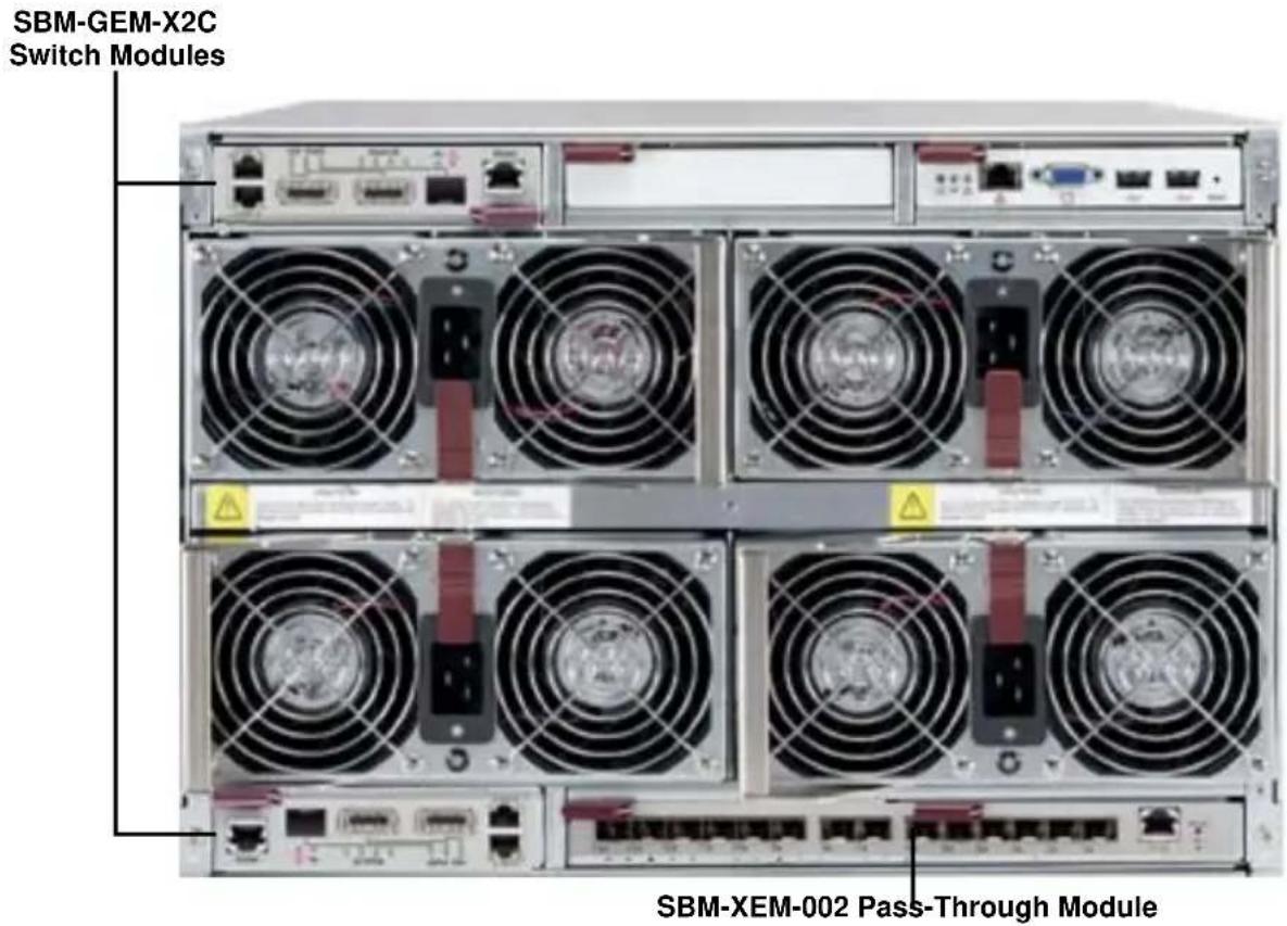
- Slide the module into the module bay until it stops (see Figure 3-1 and Figure 3-2).
Figure 3-1. Blade Enclosure with 1-Gbps Switch Modules Installed
SBM-GEM-001
Switch Modules
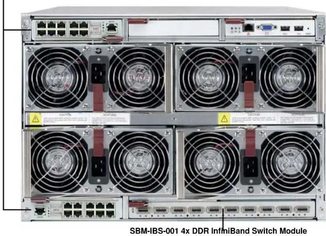
Figure 3-2. Blade Enclosure with 1/10 Gbps Switch Modules Installed
- Push the release handle to the closed position.

NOTE: After the module has been installed and the handle locked, it will turn on and a POST test will run to verify it is working properly. If there are no problems the blue Init. OK LED on the module will illuminate and you will see an OK under INITIATED in the GBE SWITCH screen of the management software utility.

NOTE: If the module is installed in a top bay it must be positioned upside-down.
Removing a Switch Module
- Pull out the release handle to the open position.
- Pull the module out of the bay.
- Replace immediately with another module or with a dummy module cover to maintain airflow integrity.
3-2 Configuring the Switch Module
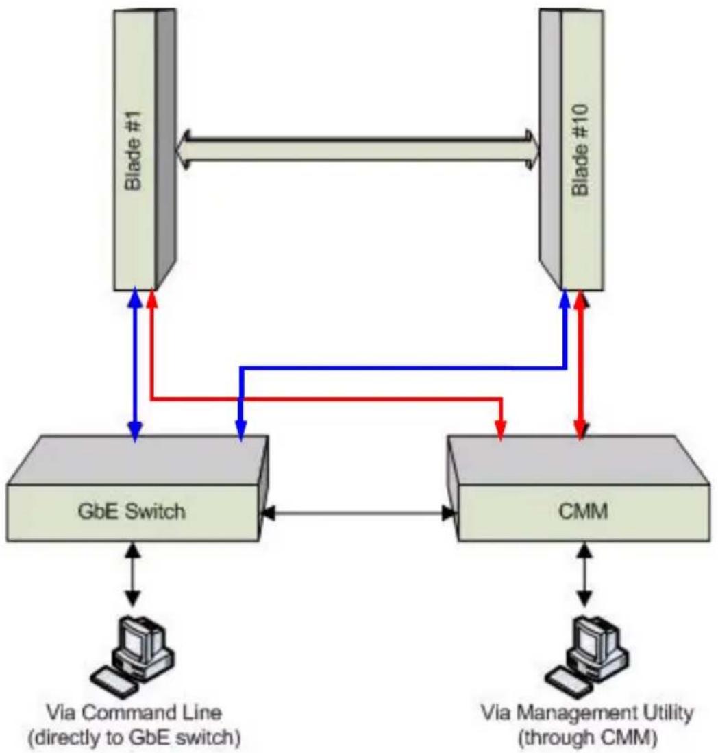
Figure 3-3. Configuring the Switch Module
flowchart
graph TD
    A["Blade #1"] <--> B["Blade #10"]
    B <--> C["GbE Switch"]
    C <--> D["CMM"]
    D <--> E["Via Command Line (directly to GbE switch)"]
    D <--> F["Via Management Utility (through CMM)"]
    C -->|Red/Blue arrows| B
    D -->|Red/Blue arrows| C
A Gigabit Ethernet switch module can be configured using two methods (as shown in Figure 3-3). You may configure it:
- Through the web-based management utility or IPMI (via the CMM module)
- Directly through a command line (using a telnet interface or a serial console)
The management utility and IPMI access the switch module through the CMM module. To access it directly, use the command line.
Note that any port may be configured as up (active) or down (inactive). All ports are active by default.
For more detailed information on configuration of the switches, see either Chapter 6: "1-Gb Ethernet Switch Firmware" on page 6-1 or Chapter 7: "1/10-Gb Ethernet Switch Firmware" on page 7-1.
Web-based Management Utility/IPMI
Using the Web-based Management Utility or IPMI is the most user-friendly method of configuring the switch module. You can access the configuration menu either through the management utility or by a network connection.
See either Chapter 6 or Chapter 7 for more details on the Web-based Management Utility.
Network Connection
Use the procedure below to connect and login to the IPMI system.
Logging In to the IPMI:
- Connect a PC to a network that is accessible to the switch.
For example, connect a PC to any of the front panel ports of the switch and make sure the PC has an IP address on the same subnet as the switch management IP.
- Type the IP address of the switch that you want to connect to in the address bar of your browser, and hit
. Once the connection is made, the LOGIN screen displays (Figure 3-4).
Figure 3-4. IPMI Login Screen
![IPMI View 72.6.37 (build 071219) - Super Micro Computer, Inc. File Edit Session Manage Help SuperBlade SuperBlade System Name SuperBlade IP Address 192.168.1.112 Description 192.168.1.112 Login ID: COLDIN [Administrator] Password: •••••••• Save ID and Password Login Layout Authentication Blade System Text Console KVM Console Event Log Logan Management Virtual Media CMM Setting Del Virtual Media information done](/content/2026/05/1141607/images/05876582739f8b7cbd800bf2bb0e528312068a37a8567183e340ce1b27def767.jpg)
a. Type in your Username in the USERNAME box.
b. Type in your Password in the PASSWORD box and click on LOGIN.

NOTE: The default username and the default password are both ADMIN. The Default IP address is 192.168.100.102.
The IPMI Blade System screen shown in Figure 3-5 is then displayed.
Figure 3-5. IPMI Blade System Screen
![TPMI View Y2.6.37 (build 071213) - Super Micro Computer, Inc. File Edit Session Manage Help SuperMICO® IPMI Domain SuperBlade Summary Failure: Blade: 10 / 10 Power: 4 / 4 Switch: 1 / 2 CMK: 2 / 2 JB: 0 / 2 Blade System Front Exit Cheese LED Power Error View Option Status Picture Number Legend Help [ Failure Summary ] Failure Table No Level Source Item Detail Side Failure Location Front Rear Authentication Blade System Text Console KVM Console Event Log Logon Management Virtual Media CMM Setting Login to SuperBlade(192.168.1.112) successfully](/content/2026/05/1141607/images/4d8cb0f59e6f3e032c03ad4a18b3cf5e22f271e384fbc4afd21944e33a1034ed.jpg)
- Clicking on a gigabit switch module will display the gigabit switch in the Gigabit Switch panel on the screen (Figure 3-6). You may make changes in the configuration of the switch module in this panel to your needs.
Figure 3-6. Gigabit Switch Panel
![[ GB Switch 1 ] Status Power Status On Error LED: Normal Initialized: OK Switch Temp: Normal 2.5V Status: Normal 1.25V Status: Normal Power Control Power On Power Off Reset Temperature 420/108F 80 Switch WebSuper:Smart Configuration Username and Password: Reset... WSS IP: 192.168.1.66 Netmask: 255.255.255.0 Gateway: 192.168.1.1 Datetime: 12/19/2007 08:58:47 Get Update Web Voltage 1.025 1.2381.375 1.25 V 2.25 2.46 2.75 2.5 V](/content/2026/05/1141607/images/5070502f326b42e5f39fc77a224e3540660dc4ac814cb1d52008eccaf2bc89a7.jpg)
Address Defaults
The following are the default addresses that are initially set. Afterwards, you can change these values within the program.
Table 3-1. SBM-GEM-001 Switch Module Address Default Settings
| Address Default Setting | |
| Default IP Address 192.168.100.102 | |
| Default Gateway Address 192.168.100.1 | |
| Default Subnet Mask 255.255.255.0 |

NOTE: If two switches are installed in a SuperBlade system, you will have to change the IP address of one from the default so that both switches have unique addresses.
Command Line
Configuring the 1/10G Ethernet switch (SBM-GEM-X2C) can be done using a command line via telnet or by using the serial console interface.
Accessing CLI through Telnet:
To access command line via telnet, follow the below steps.
- Connect a PC to a network that is accessible to the switch.
For example, connect a PC to any of the front panel ports of the switch and make sure the PC has an IP address on the same subnet as the switch management IP.
- In the PC, start a telnet client session with the switch management IP (default IP is 192.168.100.102).
This brings up the switch's command line interface for user login.
-
Enter username and password to login to the switch.
-
To view the switch configurations use show commands and to configure the switch type config term to get access to the configuration commands. For help type ? or help.
Accessing CLI through a Serial Console
To access command line via a serial console, follow the below steps.
-
Connect a PC serial port to the switch console port.
-
In the PC, open any seral port access applications, such as Hyperterminal or Term Tem.
-
Choose the serial port connected with the switch and configure with the following parameters:
$$ \text { Baudrate } = 9 6 0 0 $$
$$ \text { Data bits } = 8 $$
$$ \text { Parity } = \text { None } $$
$$ \text { Stop bit } = 1 $$
-
This brings up the switch's command line interface for user login.
-
Enter username and password to login to the switch.
-
To view the switch configurations use show commands and to configure the switch type config term to get access to the configuration commands. For help type ? or help.
3-3 SBM-GEM-X2C/+ 1/10 Gigabit Ethernet Switch Firmware
The firmware for the SBM-GEM-X2C/+ 1/10 Gigabit Ethernet switch module resides on a chip on the PCB.
The switch has internal flash memory in two areas to hold two firmware images. The flash area used for the normal firmware image is referred to as the normal area. The other flash area, referred to as the fallback area, is used to store the firmware image for fallback purpose in case of a failure to boot from the normal area.
Firmware Upgrading Procedures
The procedures for firmware upgrading and using a fallback firmware image are listed below.
Upgrading Firmware on the Switch using TFTP:
To upgrade the switch's firmware, use the procedure below.
- Copy the latest firmware to the TFTP root directory on the TFTP server machine.
- Make sure the upgraded TFTP server and switch both have network reach ability.
- Login to the Switch CLI, either through Telnet or a serial console port.
- Type the below command to upgrade the firmware in the normal area:
firmware upgrade tftp://<ip-address>/<filename>
flash:normal
Here
- On successful download CLI displays the below string:
Firmware download completed successfully.
- After a successful download, reboot the switch to use this latest firmware.
- If the download fails, check the IP address, file name, network connections and configurations to reach the TFTP server.
- If the switch does not come up after the firmware upgrade due to any incorrect firmware images, boot the switch using a fallback firmware image. Refer the steps in the procedure "Booting using a Fallback Firmware Image:" below to boot the switch using a fallback firmware image.
- Once the switch is booted with a fallback firmware, repeat the above steps to upgrade with the correct firmware image.
- On successful upgrade of the latest firmware, it is advised that you upgrade the fallback firmware image also. Follow the steps listed in the procedure "Upgrading Fallback Firmware using TFTP:" below to upgrade the fallback firmware image.
Booting using a Fallback Firmware Image:
Use the procedure below to boot using a fallback firmware image.
- Reboot the switch by power cycling the switch power.
- During reboot, press any key when it displays the below text (as shown in Figure 3-7).
Hit any key to stop autoboot: 5
Figure 3-7. Displayed Text for Rebooting
Decompressing..OK

Image Running Clock = 1
Image Running Clock = 21
system memory informations :
pool size : 25MB
free size : 21MB

PRODUCT TYPE : 24 GE Ports + 4 GE Combo Ports L2 Managed PoE Switch
Hit any key to stop autoboot: 5

ERROR: PCI configuration read(0x0=0xFFFFFFF) -READ ERROR
ERROR: PCI configuration read(0x0=0xFFFFFFF) -READ ERROR
PCI unit 0: Dev0xb313, Rev 0x01, Chip BCM56313_A0, Driver BCM56314_A0
SOC unit 0 attached to PCI device BCM56313_A0
Test chip 0......OK

<<USER MENU >>

> SYSTEM INFO:
Hardware Version : B1-01

IP Address : 192.168.2.32
Subnet Mask : 255.255.255.0
Default Gateway : 192.168.2.100
TFTP Server : 192.168.2.100
Firmware File Name : SBM-GEM-X2C-v5.2.10.bin

>MENU OPTIONS:
Press [H] to Set Hardware Info
Press [G] to Get Hardware Info
Press [F] to Download Firmware
Press [J] to Jump to Firmware

SMC>

NOTE: The numbers in the Product Type entry change depending upon the switch you are using.
- Once the boot sequence is interrupted, it will display menu options as shown in Figure 3-7.
Use the "H" option to set hardware information by typing the character H. This will display the hardware information that can be changed as shown in Figure 3-8.
Figure 3-8. Setting Hardware Information
SMC>H

> HARDWARE INFO:
Local IP (ip) = 192.168.2.32
Subnet Mask (mask) = 255.255.255.0
Default Gateway (gateway) = 192.168.2.100
TFTP Server (tftpaddr) = 192.168.2.100
Firmware Name (ramdiskname) = SBM GEM-X2C-v5.2.10.bin
Ramdisk Flag (rflag) = 0

SMC.POSC> rflag=1

> HARDWARE INFO:
Local IP (ip) = 192.168.2.32
Subnet Mask (mask) = 255.255.255.0
Default Gateway (gateway) = 192.168.2.100
TFTP Server (tftpaddr) = 192.168.2.100
Firmware Name (ramdiskName) = SBM GEM-X2C-v5.2.10.bin
Ramdisk Flag (rflag) = 1

SMC.POSC> exit

Save before Exit ? [Y/N] y

Saving Hardware Info ... OK

> HARDWARE INFO:
Local IP (ip) = 192.168.2.32
Subnet Mask (mask) = 255.255.255.0
Default Gateway (gateway) = 192.168.2.100
TFTP Server (tftpaddr) = 192.168.2.100
Firmware Name (ramdisk name) = SBM GEM-X2C-v5.2.10.bin
Ramdisk Flag (rflag) = 1
- To choose the boot from a fallback image, type the command: rflag=1
- Type Save to save the hardware information.
- Type Exit to exit the hardware information menu.
-
Type J to boot the image. In this case it will boot from a fallback image.
-
In case you wish to later move back to a normal image, repeat the above the steps with one difference for step 4, where you should use the command rflag=0 instead of rflag=1 to boot with a normal firmware image.
Upgrading Fallback Firmware using TFTP:
To upgrade fallback firmware using TFTP, use the procedure below.
- Copy the latest firmware to the TFTP root directory on the TFTP server machine.
- Make sure the upgraded TFTP server and switch both have network reach ability.
- Login to the Switch CLI either through Telnet or a serial console port.
- Type the below command to upgrade the firmware in the normal area:
firmware upgrade tftp://
Here
- On a successful download, the CLI displays the below string:
Firmware download completed successfully. - After a successful download, reboot the switch using the fallback image to verify the fallback image. Refer the steps listed above in the procedure "Booting using a Fallback Firmware Image:" above to boot the switch in the fallback image.
- Once both the normal and fallback image both have latest firmware, continue to use the normal image as directed in step 8 of the procedure "Booting using a Fallback Firmware Image:".
Firmware Failure Recovery Steps
In case you have any issues in booting the switch with either a normal or fallback image, use the procedure below to recover the switch functionality with a correctly working firmware image.
Recovering Switch Functionality with a Firmware Image:
- Copy the latest firmware to the TFTP root directory on a TFTP server machine.
-
Make sure the upgraded TFTP server and switch both have network reach ability.
-
Reboot the switch by power cycling the switch power.
-
During reboot, press any key when it displays the below text (as shown in Figure 3-7).
Hit any key to stop autoboot: 5
- Once the boot sequence is interrupted, it will display menu options as shown in Figure 3-7. Use the "H" option to set hardware information by typing the character H.
This will display the hardware information that can be changed as shown in Figure 3-8.
-
Configure the IP address for this switch (only for booting purposes) using the command: ip=
For example ip=192.168.2.3 -
Configure the subnet mask for this switch IP address using the below command:
mask=<subnet mask>
For example mask=255.255.255.0
- Configure the TFTP server IP address using the below command:
tftpaddr=<TFTP server IP>
For example tftpaddr=192.168.2.100
- Configure the gateway address to reach the TFTP server using the below command if the TFTP server is in different network:
gateway=<gateway IP>
For example gateway=192.168.2.100
- Configure the firmware image file name using the below command:
ramdiskname=<filename>
For example ramdiskname= SBM-GEM-X2C-v5.2.10.bin
-
Type Save to save the hardware information.
-
Type Exit to exit the hardware information menu.
-
Type F to download the firmware image. In this case it will download to the normal image area.
-
On a successful download, the switch displays the below string.
Updating the ramdisk image ...
This may take awhile
OK
-
After a successful download, boot the switch to use this latest firmware by typing J.
-
If the download fails, check the IP address, file name, network connections and configurations to reach the TFTP server.
Notes
Chapter 4 InfiniBand Modules
4-1 Overview
InfiniBand is a switch-based, point-to-point bidirectional serial link network communications architecture. Supermicro offers three different Infiniband modules:
- 4X DDR (20 Gb/s) switch with 14 internal ports and 10 external CX4 ports
- 4X DDR (20 Gb/s) pass-through with 14 internal ports and 14 external CX4 ports
- 4X QDR (40 Gb/s) switch with 20 internal ports and up to 18 external QSFP ports (3 models).
The main function of the SuperBlade InifiniBand switch modules is to provide high-speed interconnectivity among the blade modules and with external peripherals. These are hot-pluggable modules that must be installed in a double-wide or triple-wide bay at the lower right of the enclosure. Because they occupy one of the bays alternatively used for the CMM, only one InfiniBand module may normally be installed in the system. However, the SBM-IBS-Q3616M is an exception to this since it includes an integrated CMM. See Section 4-4: SBM-IBS-Q3616M 4X QDR InfiniBand Switch Module on page 4-4 for details.

NOTE: For any blade to access the InfiniBand module, it must first have an InfiniBand card installed on its mainboard. See Appendix A for details on the Mezzanine HCA cards that are available for use with the InfiniBand module.
4-2 SBM-IBS-001 4X DDR InfiniBand Switch Module
Figure 4-1. SBM-IBS-001 InfiniBand Switch Module
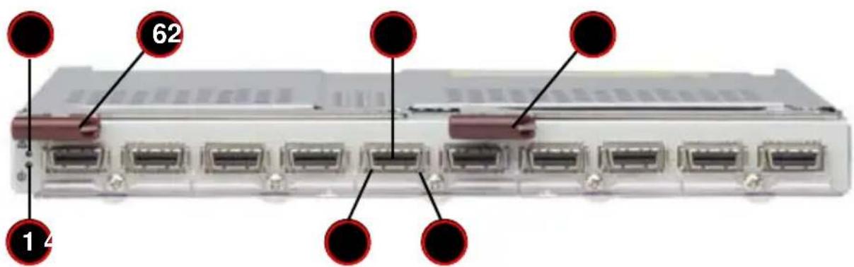
Table 4-1. SBM-IBS-001 InfiniBand Module Interface
| Item Description |
| 1 Module Power LED |
| 2 Module Status LED |
| 3 External InfiniBand Port (10 total) |
| 4 Port Physical Link LED (Green) |
| 5 Port Activity LED (Yellow) |
| 6 Module Release Handle |
Table 4-2. SBM-IBS-001 InfiniBand Module Features
| Feature Description | |
| Internal/External Ports Internal | 14 4X DDR copper ports/ External: 10 4X DDR copper ports |
| Bandwidth | 4X DDR (20 Gbps) non-blocking architecture for 960 Gbps total bandwidth (24-port) |
| Latency 160 ns port-to-port switch latency | |
| Power Consumption 34 - 40W | |
| Operating System Firmware | (upgradable) |
4-3 SBM-IBS-Q3618/Q3616 4X QDR InfiniBand Switch Module
Figure 4-2. SBM-IBS-Q3618/Q3616 InfiniBand Switch Module
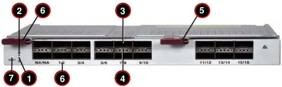
Table 4-3. SBM-IBS-Q3618/Q3616 InfiniBand Module Interface
| Item Description | |
| 1 System error. Fault LED (Red) | a |
| 2 System status. Ready LED (Green) | b |
| 3 External | InfiniBand Port (16 QSFP ports for Q3636 and 18 QSFP ports for Q3618) |
| 4 Per Port | Dual-color LED, PHY link(Green)/Logic link(Amber)/ACT blinking(Green+Amber) |
| 5 Module | Release Handle |
| 6 Port Numbers (First port number is top port, second port number is bottom port) | |
| 7 QDR Switch Reset Button | |
a. If the fault LED goes on, the QDR switch operation is stopped. It then needs a hardware reset or a power off cycle to bring it back into normal operation.
b. If the Green LED is blinking, the QDR switch is overheated. Please check the air fan and vent condition. If the fault LED goes on at the same time, a hard reset or a power off cycle needs to be initiated.
Table 4-4. SBM-IBS-Q3618/Q3616 InfiniBand Module Features
| Feature Description | |
| Internal/External Ports | Internal: 18/20 4X QDR copper ports/ External: 18/16 4X QDR copper ports |
| Bandwidth | 4X QDR (40 Gbps) non-blocking architecture for 2.88 Tbps total bandwidth (36-port) |
| Latency 120 ns port-to-port switch latency | |
| Power Consumption 100W | |
| Operating System Firmware | (upgradable) |
4-4 SBM-IBS-Q3616M 4X QDR InfiniBand Switch Module
Figure 4-3. SBM-IBS-Q3616M InfiniBand Switch Module
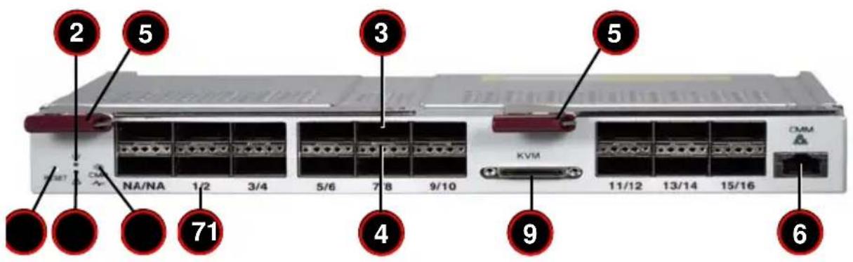
Table 4-5. SBM-IBS-Q361M InfiniBand Module Interface
| Item Description | |
| 1 System error. Fault LED (Red) | a |
| 2 System status. Ready LED (Green) | b |
| 3 External | InfiniBand Port (16 QSFP ports for Q3636 and 18 QSFP ports for Q3618) |
| 4 Per Port | Dual-color LED, PHY link(Green)/Logic link(Amber)/ACT blinking(Green+Amber) |
| 5 Module | Release Handle |
| 6 Internal | CMM Module Ethernet Port |
| 7 Port Numbers (First port number is top port, second port number is bottom port) | |
| 8 QDR Switch Reset and CMM Load Default | |
| 9 KVM Connector | |
| 10 CMM Activity LED | |
a. If the fault LED goes on, the QDR switch operation is stopped. It then needs a hardware reset or a power off cycle to bring it back into normal operation.
b. If the Green LED is blinking, the QDR switch is overheated. Please check the air fan and vent condition. If the fault LED goes on at the same time, a hard reset or a power off cycle needs to be initiated.
Table 4-6. SBM-IBS-Q3616M InfiniBand Module Features
| Feature Description | |
| Internal/External Ports Internal | 20 4X QDR copper ports/ External: 16 4X QDR copper ports |
| Bandwidth | 4X QDR (40 Gbps) non-blocking architecture for 2.88 Tbps total bandwidth (36-port) |
| Latency 120 ns port-to-port switch latency | |
| Power Consumption 120W (with CMM Module Loaded) | |
| Operating System Firmware (upgradable) | |
In addition to the InfiniBand switching capability it shares with other Supermicro Blade InfiniBand switches, the SBM-IBS-Q3616M module includes provision for the installation of an optional integrated Chassis Management Module (CMM). This “mini-CMM” (BMB-CMM-002) is installed as an add-on-module inside the switch chassis. This allows installation of two (redundant) switches in the SuperBlade enclosure without the loss of system management capability. Note that a dual-port InfiniBand add-on card is required if redundant switches are installed.
Either the RJ45 connector or the KVM connector on the front of the SBM-IBS-Q3616M can be used to connect to the integrated CMM module (see Figure 4-3). There is also an activity indicator LED for the CMM on the left-hand side of the front of the SBM-IBS-Q3616M.
The reset button (lower left), pushed once, will reset the SBM-IBS-Q3616M. If held down for approximately 5 seconds it will send a signal to the CMM, which cause the CMM to return to default settings.
See Chapter 4, Section 4.1 of the SuperBlade User's Manual for more information on the operation of the CMM itself, including instructions on how to use both the KVM and RJ45 connections.
4-5 SBM-IBP-D14 InfiniBand Pass-Through Module
Figure 4-4. SBM-IBP-D14 InfiniBand Pass-Through Triple-Wide Module
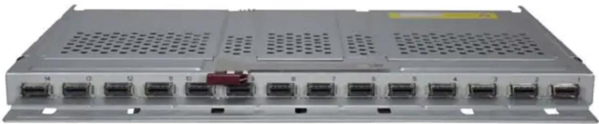
natural_image
Front view of a network switch device with multiple ports and ventilation grilles (no visible text or labels)The SBM-IBP-D14 InfniBand Pass-through Module is a triple-wide non-configurable pass-through module that includes fourteen (14) 4X DDR copper ports with CX-4 connectors. The pass-through module is used to provide a connection between the Infiniband controller (Add-on Card) mounted on the blade's mainboard and an external InfiniBand device.
Unlike the SBM-IBS-001 4x DDR InfiniBand switch module, this is a pass-through module. With this module Blade 1 would be connected directly to port 1, Blade 2 to port 2 and so on. If you are only connected to 10 blades then ports 11 through 14 are not connected.
Temperature and voltage of the pass-through module are read through the CMM module. Like other SuperBlade network modules, this pass-through module is hot-pluggable.

NOTE: The SBM-IBP-D14 InfniBand Pass-through Module must be connected to another InfniBand module in order to operate.
4-6 Installation and Configuration of InfiniBand Switch Modules
This section covers the installation, removal and configuration of InfiniBand switch modules and InfiniBand pass-through modules.
Installing/Removing the InfiniBand Switch Module
Before installing the InfiniBand switch module make sure the cover to the module has been installed before proceeding. Refer to the anti-static precautions described in Chapter 2.
The InifiniBand switch module must be installed into a double-wide bay. Assuming that you have already created a double-wide bay out of two single-wide bays, continue with the steps below. See the SuperBlade User's Manual for details on setting up double-wide bays in the SuperBlade enclosure.

NOTE: The 10GbE Pass-through module (SBM-XEM-002) also requires the same double-wide bay as the InfiniBand switch module and may be installed instead of the InfiniBand switch module in your blade enclosure system. Use the same instructions below for installing either the pass-through module or the InfiniBand switch module.
Installing the Module
- Remove the dummy cover from the bay you want to place the module in.
- Place the module's release handle in the open position.
- Slide the module into the module bay until it stops.
- Push the release handle to the closed position.
After the module has been installed and the handle locked, it will power on after a short delay and a POST test will run to verify it is working properly.
Removing the Module
- Pull out the release handle to the open position.
- Pull the module out of the bay.
- Replace immediately with another module or with a dummy module cover to maintain airflow integrity.
Installing/Removing the InfiniBand Pass-Through Module
Before installing the InfiniBand pass-through module make sure the cover to the module has been installed before proceeding. Refer to the anti-static precautions described in Chapter 2.
The InifiniBand pass-through module must be installed into a triple-wide bay. For instructions on how to create a triple-wide bay, see Appendix C.
Assuming that you have already created a triple-wide bay out of three single-wide bays, continue with the steps below.
Installing the Module
- Remove the dummy cover from the bay you want to place the module in.
- Place the module's release handle in the open position.
- Slide the module into the module bay until it stops.
- Push the release handle to the closed position.
Removing the Module
- Pull out the release handle to the open position.
- Pull the module out of the bay.
- Replace immediately with another module or with a dummy module cover to maintain airflow integrity.
InfiniBand Switch LEDs
InfiniBand switch LEDs are listed and described in Table B-4 in Appendix B.
Blade Software for Access to InfiniBand Switch Module
The InfiniBand Switch Module is an unmanaged switch and requires no configuration. Blades which are to be connected to it will require an appropriate driver software package to be installed.
The Windows software package (WinOF) can be downloaded from: http://www.mellanox.com/content/pages.php?pg=products_dyn&product_family=32&menu_section=34
The Windows ReadMe is available at:
http://www.mellanox.com/related-docs/prod_software/Mellanox_WinOF_VPI_Readme.pdf
Linux OFED software package is available from the following link:
http://www.mellanox.com/content/ pages.php?pg=products_dyn&product_family=26&menu_section=34
Linux release notes:
http://www.mellanox.com/related-docs/prod_software/MLNX_OFED_1_5_1_release_notes.txt
Chapter 5 Ethernet Modules
Your SuperBlade enclosure can include either of two models of Ethernet switch modules or two models of Ethernet pass-through modules installed in it.
The Ethernet switch modules and the SBM-GEM-002 Gigabit pass-through module can only be installed in the upper and/or lower left module bays, whereas the SBM-XEM-002 10-Gigabit pass-through module must be installed in a double-wide slot in the enclosure in a location alternately used for the InfiniBand switch module. The InfiniBand module is discussed in Chapter 4.
5-1 SBM-GEM-001 Gigabit Ethernet Switch Module
The SBM-GEM-001 Gigabit Ethernet switch module is a layer 2 Ethernet switch. It includes ten 1-Gb/s uplink (RJ45) ports and fourteen 1-Gb/s downlink ports for the SuperBlade's LAN interfaces. The Gigabit Ethernet switch module has two internal Ethernet paths to the CMM(s). The switch is used to provide a connection between the Ethernet controller integrated on the mainboard and an external Ethernet device. This is a hot-pluggable module. See Figure 5-1, Table 5-1 and Table 5-2 for switch details.
Figure 5-1. SBM-GEM-001 Gigabit Ethernet Switch Module
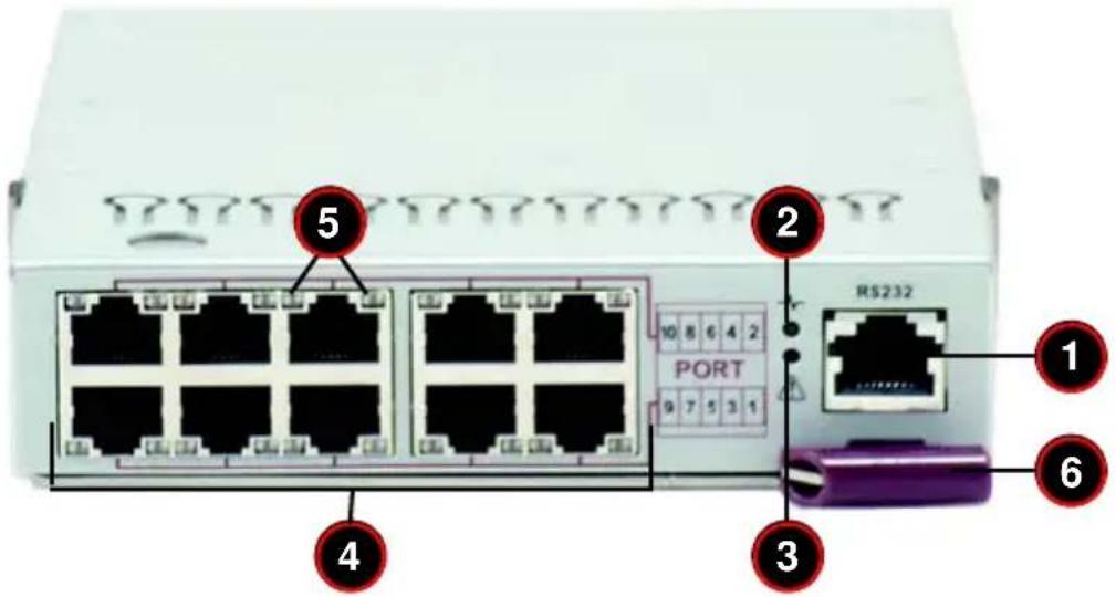
Table 5-1. SBM-GEM-001 Gigabit Ethernet Switch Module Interface
| Item Description |
| 1 RS232 (COM) Serial Port |
| 2 “Initiation OK” LED |
| 3 Module Fault LED |
| 4 RJ45 Ethernet Ports |
Table 5-1. SBM-GEM-001 Gigabit Ethernet Switch Module Interface (Continued)
| Item Description | |
| 5 Ethernet | Port Status LEDs |
| 6 Module | Release Handle |
Table 5-2. GEM-001 Gigabit Ethernet Switch Module Features
| Feature Description | |
| Chipset Broadcom BCM5345M | |
| Internal/External Ports | Internal: Fourteen 1 Gbps downlink ports / External: Ten 1 Gbps RJ45 uplink ports |
| Bandwidth 24 Gbps non-blocking | |
| Trunking Link aggregation support | |
| Jumbo Frame Support Up to 9 kb | |
| Remote Management Browser-based management | |
| Protocols Spanning Tree, Rapid Spanning Tree, Multiple Spanning Tree (802.1d.1w) | |
| Power Consumption ~30.6W | |
| Operating System | Firmware (see Section 3-3: SBM-GEM-X2C/+ 1/10 Gigabit Ethernet Switch Firmware on page 3-9 for details) |
LED Indicators
LED indicators for the SBM-GEM-001 Gigabit Ethernet switch module are listed and described in Table B-1 of Appendix B.
Ports
The SBM-GEM-001 Gigabit Ethernet switch module contains several front-mounted ports as described below in Table 5-3.
Table 5-3. SBM-GEM-001 Gigabit Ethernet Switch Module Ports
| Port Description | |
| RS-232 Compatible Serial Port | This port accepts an connector cable for uplink using RS-232 connection to a console. |
| RJ45 Ethernet Ports | These two ports accept a RJ45 connector for 1-Gbps uplink communications. |
5-2 SBM-GEM-X2C 1/10 Gb Ethernet Switch Module
The SBM-GEM-X2C 1/10 Gigabit Ethernet switch module is a layer 2/3 Ethernet switch. It includes three 10-Gb/s uplink ports (two CX4 and one SPF+), two 1-Gb/s uplink RJ45 uplink ports and fourteen 1-Gb/s downlink ports for the SuperBlade's LAN interfaces. The Ethernet switch module has two internal Ethernet paths to the CMM(s). The switch is used to provide a connection between the Ethernet controller integrated on the mainboard and an external Ethernet device. This is a hot-pluggable module. See Figure 5-2, Table 5-4 and Table 5-5 for switch details.
Figure 5-2. SBM-GEM-X2C 1/10 Gigabit Ethernet Switch Module Ports and Indicators
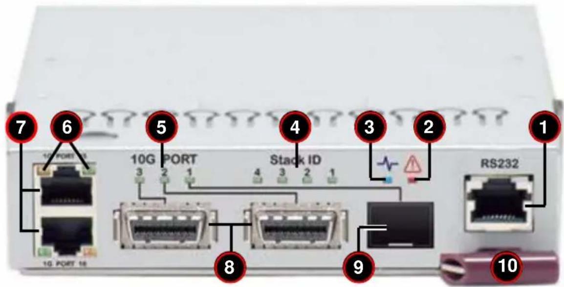
Table 5-4. SBM-GEM-X2C 1/10 Gigabit Ethernet Switch Module Interface
| Item Description | |
| 1 RS-232 (COM) Serial Port | |
| 2 Module Fault LED | |
| 3 “Initiation OK” LED | |
| 4 Stack ID LEDs (4) | |
| 5 10-Gbps Uplink Port Status LEDs (3) | |
| 6 1-Gbps RJ45 Uplink Port Status LEDs (Link/Activity and Speed) | |
| 7 1-Gbps RJ45 Uplink Ports (2) | |
| 8 CX4 10-Gbps Uplink Ports (2) | |
| 9 SFP+ 10-Gbps Uplink Port | |
| 10 Module Release Handle |
Table 5-5. SBM-GEM-X2C 1/10 Gigabit Ethernet Switch Module Features
| Feature Description | |
| Chipset Broadcom BCM56313 | |
| Internal/External Ports | Internal: Fourteen 1-Gbps downlink portsExternal: Two 1-Gbps RJ45 uplink ports and Three 10-Gbps uplink ports (1 SPF+, 2 CX4) |
| Bandwidth 24 Gbps non-blocking | |
| Trunking Link aggregation support | |
| Jumbo Frame Support Up to | 9 kb |
| Remote Management Browser-based management | |
| Protocols | Spanning Tree, Rapid Spanning Tree, Multiple Spanning Tree, IGMP snooping and 802.1x |
| Power Consumption ~30.6W | |
| Operating System | Firmware (see Section 3-3: SBM-GEM-X2C/+ 1/10 Gigabit Ethernet Switch Firmware on page 3-9 for details) |
LED Indicators
LED indicators for the SBM-GEM-X2C 1/10 Gigabit Ethernet switch module are listed and described in Table B-2 of Appendix B.
Ports
The SBM-GEM-X2C 1/10 Gigabit Ethernet switch module contains several front-mounted ports as described below in Table 5-6.
Table 5-6. SBM-GEM-X2C Ports
| Port Description | |
| RS-232 Compatible Serial Port | This port accepts an connector cable for uplink using RS-232 connection to a console. |
| RJ45 Ethernet Ports | These two ports accept a RJ45 connector for 1-Gbps uplink communications. |
| CX4 10-Gbps Ports | These two ports accept a CX4 10GBase-CX4 connectors for 10-Gbps uplink communications or for stacking. |
| SFP+ 10-Gbps Port | This port accepts a SFP+ Direct Attach connector for 10-Gbps uplink communications. |
5-3 SBM-GEM-002 1Gb Ethernet Pass-through Module
The SBM-GEM-002 Gigabit pass-through module is a non-configurable pass through module that includes fourteen (14) 1-Gb/s uplink (RJ45) ports and fourteen 1-Gb/s downlink ports for the SuperBlade's LAN interfaces. This Ethernet module has two internal Ethernet paths to the CMM(s). The switch is used to provide a connection between the Ethernet controller integrated on the mainboard and an external Ethernet device.
Unlike the SBM-GEM-001 Gigabit Ethernet switch module, this is a pass-through module and is not configurable. With this module Blade 1 would be connected directly to port 1, Blade 2 to port 2 and so on. If you are only connected to 10 blades then ports 11 through 14 are not connected.
Temperature and voltage of the pass-through module are read through the CMM module. The LED's of the pass-through for a blade are only lit when the blade is on. Like the SBM-GEM-001 Gigabit Ethernet switch module, this pass-through module is a hot-pluggable module. See Figure 5-3, Table 5-7 and Table 5-8 for switch details.

NOTE: The SBM-GEM-002 Gigabit pass-through module must be connected to another Gigabit Ethernet switch module in order to operate. If you connect it to a 10/100 switch, it will not work.
Figure 5-3. SBM-GEM-002 Gigabit Pass-through Module
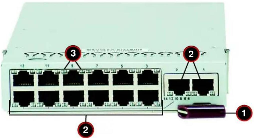
Table 5-7. SBM-GEM-002 Gigabit Pass-through Module Interface
| Item Description | |
| 1 Module Release Handle | |
| 2 RJ45 Ethernet Ports | |
| 3 Ethernet Port Status LEDs |
Table 5-8. SBM-GEM-002 Gigabit Ethernet Pass-through Module Features
| Feature Description | |
| Internal/External Ports | Internal: Fourteen 1 Gbps downlink ports / External: fourteen 1 Gbps RJ45 uplink ports |
| Remote Management NA | |
| Protocols NA | |
| Power Consumption ~30.6W |
5-4 SBM-XEM-002/SBM-XEM-002M 10 Gb Ethernet Pass-through Module
The SBM-XEM-002, and the newer SBM-XEM0-002M 10-Gigabit pass-through modules are non-configurable pass through modules that includes 14 (fourteen) 10-Gb/s uplink (SFP+) ports and 14 10-Gb/s internal downlink (XAUI) ports for the SuperBlade's LAN interfaces.
The SBM-XEM-002M 10-Gigabit pass-through module includes connectors and circuitry that allow the installation of an optional mini-CMM module (BMB-CMM-002). See the SuperBlade User's Manual for information on the installation and operation of the mini-CMM module. The RJ45 connector is used for console connection to the mini-CMM module.
The SBM-XEM-002 10-Gigabit pass-through module must be installed in a double-wide slot in the enclosure. It is installed in a location that is alternately used for the InfiniBand switch module. See the SuperBlade User's Manual for details.

NOTE: For any blade to access the 10-Gigabit pass-through module, it must first have one of the Connect-X based add-on InfiniBand cards installed on its mainboard (AOC-IBH-XDS or AOC-IBH-XDD, AOC-IBH-XDS, AOC-IBH-XDD or AOC-IBH-XDS or AOC-IBH-XDD cards). See Appendix A for details on the AOC cards.
Unlike the SBM-GEM-001 or SBM-GEM-X2C Ethernet switch modules, this is a pass-through module, and just like the SBM-GEM-002 1Gb Ethernet Pass-through Module model described above, it is not configurable.
With this module Blade 1 would be connected directly to port 1, Blade 2 to port 2 and so on. If you are connected to 10 blades then ports 11 through 14 are not connected.
Temperature and voltage of the pass-through module are read through the CMM module. The LED's of the pass-through for a blade are only lit when the blade is on. Like the other switches, this pass-through module is a hot-pluggable module. See Figure 5-4, Table 5-9 and Table 5-10 for switch details.

NOTE: The SBM-XEM-002 10-Gigabit pass-through module must be connected to another 10 Gigabit Ethernet switch module in order to operate. If you connect it to a 10/100/1000 switch, it will not work.
Figure 5-4. SBM-XEM-002 10-Gigabit Pass-through Module
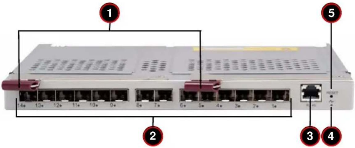
| Item Description | |
| 1 Module Release Handles | |
| 2 10-Gbp/s | Uplink SFP+ Ports |
| 3 RJ45 Ethernet Port for connection to console for mini-CMM | |
| 4 “Initiation OK” LED for mini-CMM | |
| 5 Reset Button for mini-CMM | |
Table 5-10. SBM-XEM-002 10-Gigabit Pass-through Module Features
| Feature Description | |
| Internal/External Ports | Internal: Fourteen 10-Gbps downlink ports to internal 10-Gbps Mezzanine Add-on Card / External: fourteen 10-Gbps SFP+ uplink ports |
| Remote Management NA | |
| Protocols NA | |
| Power Consumption ~30.6W |
5-5 SBM-GEP-T20 1Gb Ethernet Pass-through Module for Twin-Blade Modules
The SBM-GEP-T20 Gigabit pass-through module is a non-configurable pass through module that includes twenty (20) 1-Gb/s uplink (RJ45) ports and twenty (20) 1-Gb/s downlink ports for the SuperBlade's LAN interfaces. This Ethernet module has an internal I²C path to the CMM. The pass-through module is used to provide a connection between the Ethernet controller integrated on the mainboard and an external Ethernet device.
Unlike the SBM-GEM-001 Gigabit Ethernet switch module, this is a pass-through module and is not configurable. With this module Blade 1 would be connected directly to port 1, Blade 2 to port 2 and so on. If you are only connected to 10 blades then ports 11 through 20 are not connected.
Temperature and voltage of the pass-through module are read through the CMM module. The LED's of the pass-through for a blade are only lit when the blade is on. Like the SBM-GEM-001 Gigabit Ethernet switch module, this pass-through module is a hot-pluggable module. See Figure 5-5, Table 5-11 and Table 5-12 for switch details.

NOTE: The SBM-GEP-T20 Gigabit pass-through module must be connected to another Gigabit Ethernet switch module in order to operate. If you connect it to a 10/100 switch, it will not work.
Figure 5-5. SBM-GEP-T20 Gigabit Pass-through Module
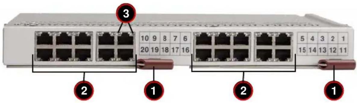
Table 5-11. SBM-GEP-T20 Gigabit Pass-through Module Interface
| Item Description | |
| 1 Module Release Handles | |
| 2 RJ45 Ethernet Ports | |
| 3 Ethernet Port Status LEDs |
Table 5-12. SBM-GEP-T20 Gigabit Ethernet Pass-through Module Features
| Feature Description | |
| Internal/External Ports | Internal: Twenty 1 Gbps downlink ports / External: twenty 1 Gbps RJ45 uplink ports (fixed speed at 1 Gbps) |
| Remote Management NA | |
| Protocols NA | |
| Power Consumption ~30.6W |
The SBM-GEP-T20 is a double-wide module. It installs in the upper left-hand slot in the rear of the SuperBlade enclosure. Only one SBM-GEP-T20 is supported per enclosure (see Figure 5-6).
Figure 5-6. SBM-GEP-T20 Installed in Enclosure
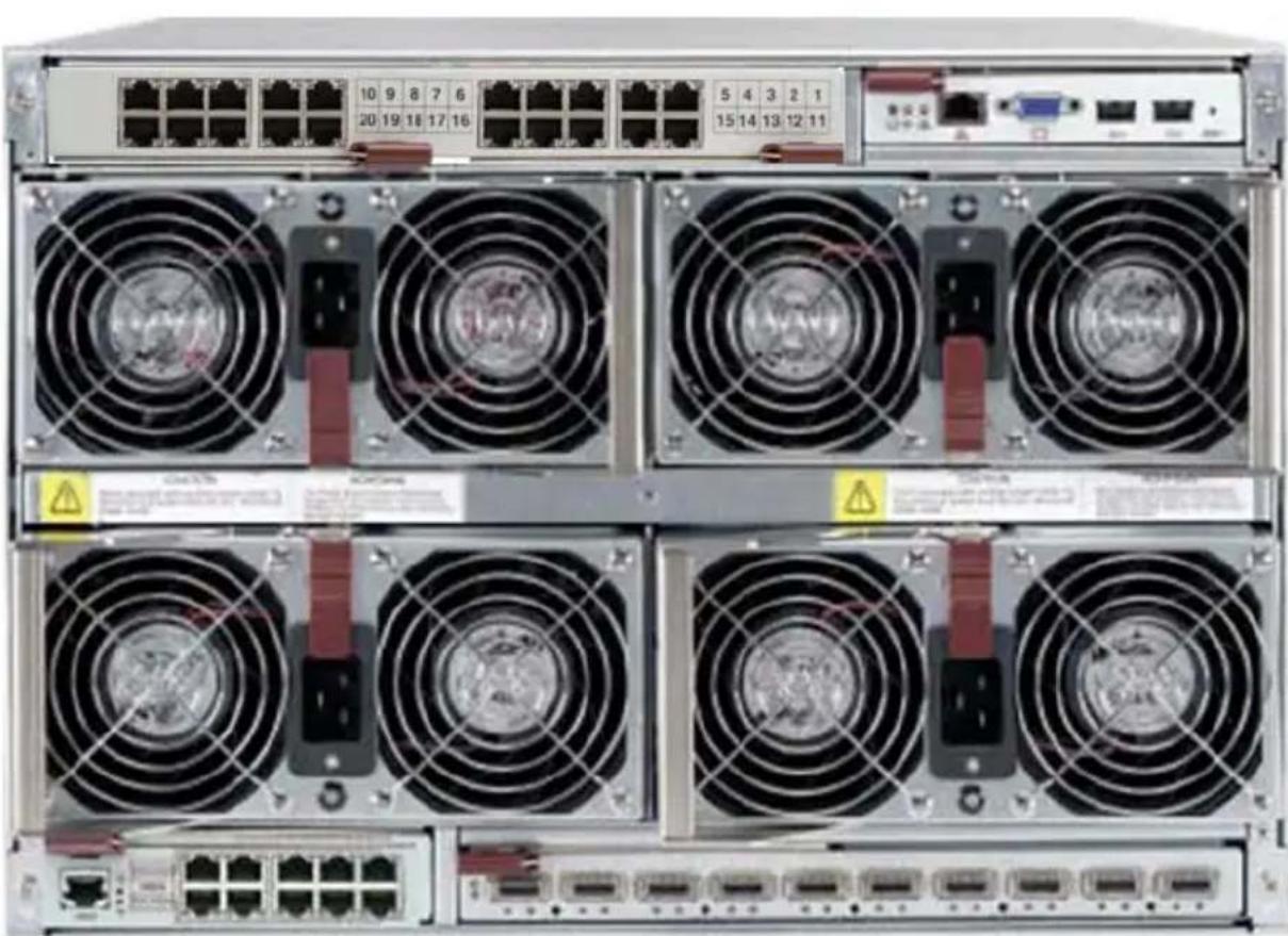
natural_image
Front view of a server rack with multiple drive fuses and ports (no visible text or labels)Notes
Chapter 6 1-Gb Ethernet Switch Firmware
The firmware configuration system for the SBM-GEM-001 Gigabit Ethernet switch module is covered in this chapter.
6-1 SBM-GEM-001 Firmware Features and Functions
Table 6-1 provides a summary of features and functions for the Gigabit Ethernet switch module firmware.
Table 6-1. SBM-GEM-001 Software Features and Functions
| Item | Functions Features | |
| Basic Functions | Throughput | 24Gbps(14 internal 1Gbps + 10 external 1Gbps) |
| Latency Average 2.65usec (frame size 1518 bytes) | ||
| Switching mode Store-and-forward | ||
| MAC address learning table size 8192 entries | ||
| MAC address learning IVL (Independent VLAN learning) | ||
| Jumbo frame support Up to 9216 bytes | ||
| Flow control 802.3x pause frame flow control | ||
| Broadcast Storm Control Support per-system control types and rates | ||
| Ingress rate control Support per-port rate control | ||
| Scalability Trunk | Port mirroring | A copy of ingress and egress data of the monitored port is sent to snooping port |
| ng (Static Link Aggregation) | Increase bandwidth and redundancy.Up to 8 ports per trunk, 4 trunks per switch. | |
| Redundancy | IEEE802.1D STPIEEE802.1W RSTP | To make a loop-free and redundant network using RSTP. RSTP is upward compatible with legacy STP. |
| VLAN IEEE802.1q VLAN Supports 256 VLAN groups. | ||
| QoS | IEEE802.1p QoS | Supports 802.1p priority queuing and 4 priority queues per port. |
| Multicast | IGMP v1/v2 Snooping | Prevents unnecessary forwarding of multicast packets to reduce multicast traffic. |
| Management | SNMP agent | Supports SNMP v1 and v2c |
| Http server | Forwarding | |
To configure the switch, select the switch you want in the SWITCH STATUS screen in the Web-based Management Utility. See the Web-based Management Utility User's Manual for details.
A SWITCH STATUS screen will appear (Figure 6-1) in your browser.
Figure 6-1. Switch Status Screen
![Supermicro® Home KVM Console Blade System Virtual Media System Health User Management KVM Settings Device Settings Maintenance Gigabit Switch List [Gigabit Switch 1] [Gigabit Switch 2] [Gigabit Switch Status] Gigabit Switch Status Gigabit Switch Pwr Status 2.5V 1.25V Temp Error Initialized Gigabit Switch 1 On 2.48V 1.20V 47C/11F Normal OK Power on Power off Reset Gigabit Switch Management IP address 192.168.100.103 Subnet mask 255.255.255.0 Gateway IP address 192.168.100.1 Date & Time 04/01/2008 17:21:15 Save Configuration Web Management Gigabit Switch Username & Password Reset Username Password Confirm Password >Shmt](/content/2026/05/1141607/images/df79acbec3ebdc98710a447270359cde15c5b66426027d5280184046a3034b4f.jpg)
In this screen, either select WEB MANAGEMENT or type the IP address of the switch (usually 192.168.100.102) in the address field of your web browser. The SYSTEM MANAGEMENT screen shown in Figure 6-2 appears.
Figure 6-2. Switch System Management Screen
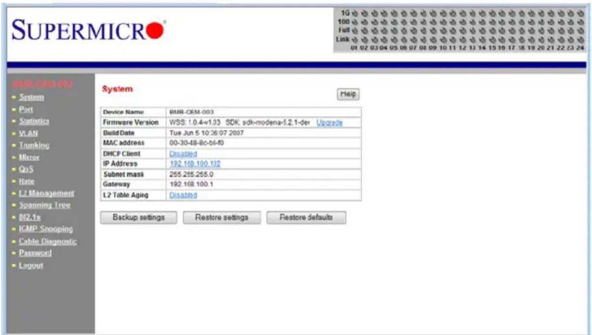

NOTE: You will see "BMB-GEM-003" on most of these screens. This the board model number for the SBM-GEM-001 switch and is sometimes used interchangeably with it in describing the product.
6-1 Port Status
The PORT STATUS screen provides a status overview of the switch's 24 ports. As shown in Figure 6-3, it includes link, speed, duplex, flow control, jumbo frame and PVID. In this screen click on PORT on the left menu bar. The port status will show up. To retrieve and update to the latest status, click the REFRESH button.
Figure 6-3. Port Status Screen
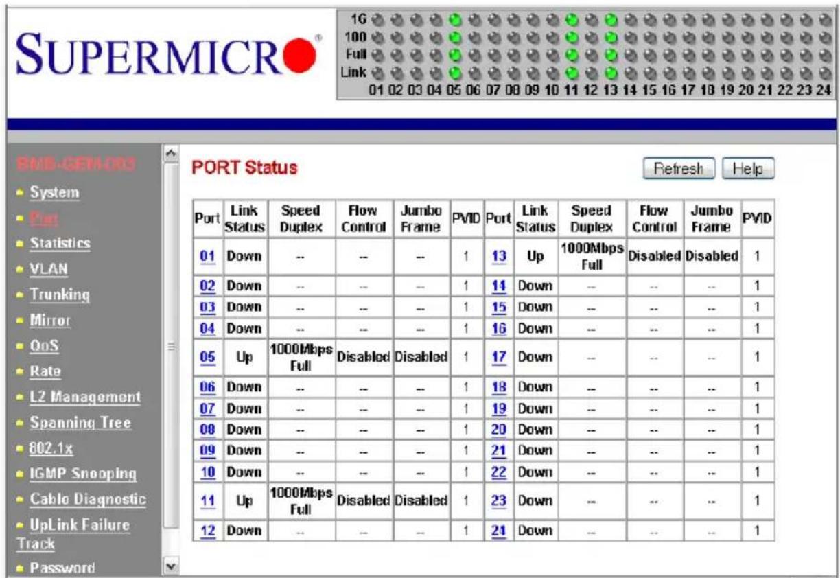
The PORT column indicates the port number of the switch.
The LINK STATUS column shows the current link status (either up or down) for each port.
The SPEED DUPLEX column indicates the link speed and duplex status for each port when it is linked up. If the link is down, there is no status shown on SPEED DUPLEX.
The FLOW CONTROL column indicates that the state of flow control is either disabled or enabled for each port when it is linked up.
The JUMBO FRAMES column indicates that the state of jumbo frame support is either disabled or enabled for each port when it is linked up.
The PVID column shows the current default port VLAN ID for each switch port.

NOTE: In the figures BMB-GEM-003 is the number of the Gigabit switch board; it is not a separate model of switch.
Port VLAN ID (PVID)
The PVID is used in a port-based VLAN to allow assigning a port to belong to a VLAN. A VLAN can then be configured to be a group of member ports. This switch is an 802.1q tag-aware switch. If no VLANs are defined on the switch, every port will be assigned to a default VLAN which has VLAN ID 1. Each port will have PVID equal to 1.
If incoming frames are untagged, they will be tagged with the default PVID of the port on which they are received. The destination MAC address of the frame and the PVID will be used for forwarding decisions. An incoming tagged frame will be kept intact. The switch will use the VID in the frame and the destination MAC address for the forwarding decision. Look for a more detailed description in the VLAN section.
Jumbo Frames Support
To modify the jumbo frames support for all of ports, click on the EDIT OF JUMBO FRAME setting (as shown in Figure 6-3) to link to the JUMBO FRAME SETTING screen (Figure 6-4). Click the ENABLE JUMBO FRAME check box to enable/disable jumbo frame support.
Figure 6-4. Jumbo Frame Setting Screen
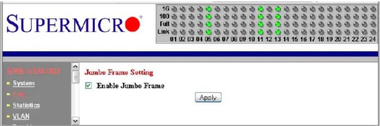
When a jumbo frame is enabled, the maximum length of a frame that can be forwarded by a switch is 9216. When the jumbo frame is disabled, the maximum length of a frame that can be forwarded by a switch is 1518.
Port Configuration
To modify the configuration of each port, click on the port number in the PORT STATUS screen (see Figure 6-3). The PORT CONFIGURATION screen appears (Figure 6-5). It is used to define speed and duplexing for a port when auto-negotiation is off. When auto-negotiation is on, this data is negotiated with the link partner.
Figure 6-5. Port Configuration Screen
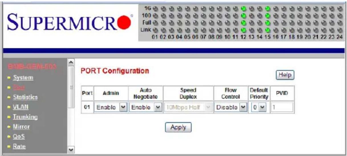
Table 6-2. Port Configuration Screen Controls
| Control Description | |
| Port Specifies the port | number to control. |
| Admin Enables or disables the port. | |
| Auto Negotiation | Enables or disables auto-negotiation. When auto-negotiation is enabled, the port negotiates with the link partner and works out speed, duplex operation, and flow control. When auto-negotiation is disabled, port speed, duplex operation, and flow control is programmable by the user. |
| Duplex Speed Indicates | duplex state and speed of the port. |
| Flow Control | Turns flow control on or off. When flow control of the port is on, it sends out a Pause frame or a Jam Packet if it is over-subscribed. When this port receives a Pause Frame or Jam Signal, it will postpone sending for a certain period to send out a frame by IEEE definition. |
| Default Priority | Assigns packet priority for packets arriving at the port without tagging. If the packet comes in with tag or priority-tag, the priority is retrieved from the priority field of the tag. |
| PVID | Assigns default port VLAN ID for the port. When the port receives a frame which is untagged or priority tagged (VLAN ID = 0), the PVID will be used for forwarding decision for these two kind of frame. |
6-2 Statistics
The STATISTICS screen displays the total number of packets transmitted or received on each port as shown in Figure 6-6. Click on the REFRESH button to retrieve the current count and update the screen. Click on the CLEAR COUNTERS button to reset the count to zero for each port. Click on each port number to retrieve detail statistic information for that particular port.
Figure 6-6. Statistics Screen
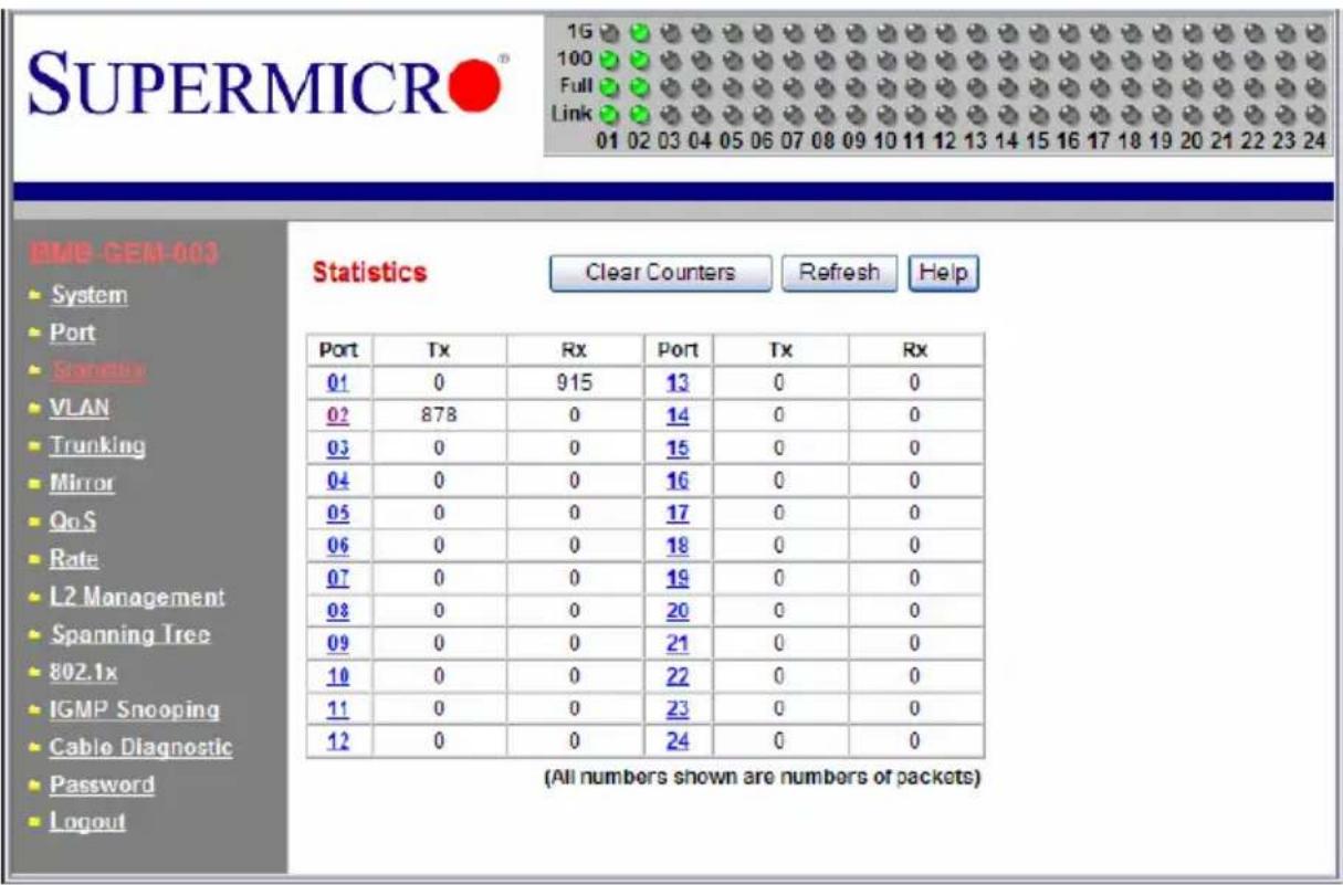
Port Statistics
The PORT STATISTICS screen (Figure 6-7) displays detailed traffic statistics for each port to help a user analyze network operations such as traffic bytes, errors, number of packets, etc. These traffic statistics are shown in Table 6-3.
Figure 6-7. Port Statistics Screen
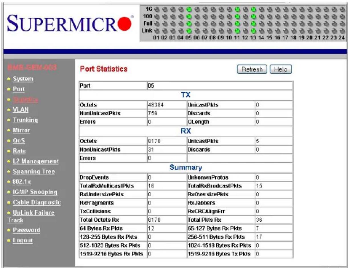
Table 6-3. Port Statistics Screen Controls
| Control Description | |
| TX Displays traffic information on outgoing frames. | |
| Octets Indicates total octets transmitted. | |
| UnicastPkts This indicates transmitted unicast packets. | |
| NonUnicastPkts This indicates transmitted non-unicast packets. | |
| Discards This indicates discarded packets. | |
| Errors This indicates Excessive Collision packets. | |
| QLength This indicates count of packets currently buffered. | |
| RX | Displays traffic information on incoming frames. |
| Octets Indicates total octets received. | |
| UnicastPkts Indicates received unicast packets. | |
| NonUnicastPkts Indicates received non-unicast packets. | |
| Discards Indicates discarded packets. | |
| Errors | Indicates undersize/fragment/FCS error/oversized errors with good FCS packets. |
| Summary | Displays traffic information by packet type, type of error and frame size range. |
| DropEvents | Indicates events in which packets are dropped due to a lack of resources. This includes events where the receiving shared buffer is full, and events when a transmission failure is due to a late collision. |
| UnknownProtos | Indicates received packets using unknown protocols, such as packets that are dropped due to reasons other than drop events and storm limits. |
| TotalRxMulticastPkts Indicates the total received multicast packets. | |
| TotalRxBROADCASTPkts Indicates the total received broadcast packets. | |
| RxUndersizePkts | Indicates received packets with a length that is less than the minimum packet size. |
| RxOversizePkts | Indicates received packets with length more than the maximum packet size. |
| RxFragments | Indicates received packets (length 10 ~ 63 bytes) with an invalid FCS or an alignment error. |
| RxJabbers | Indicates received packets (invalid FCS or code error) that exceed the counter maximum size to the maximum received frame length. |
| TxCollisions Indicates the total transmitted collision packets. | |
| RxCRCAlignErr | Indicates received packets (invalid FCS) that have a length between 64 bytes and the counter maximum size. |
| Total Octets Rx | Indicates total number of octets of data received (excluding framing bits, but including FCS bytes). |
| Total Pkts Rx | Indicates total received packet count (including all bad packets, unicast, broadcast, multicast and MAC control packets). |
| 64 Bytes Rx Pkts | Indicates received packets with a packet length that is less than or equal to 64 bytes. |
| 65-127 Bytes Rx Pkts | Indicates received packets with a packet length that is between (includes) 65 ~ 127 bytes. |
| 128-255 Bytes Rx Pkts | Indicates received packets with a packet length that is between (includes) 128 ~ 255 bytes. |
| 256-511 Bytes Rx Pkts | Indicates received packets with a packet length that is between (includes) 256 ~ 511 bytes. |
| 512-1023 Bytes Rx Pkts | Indicates received packets with a packet length that is between (includes) 512 ~ 1023 bytes. |
| 1024-1518 Bytes Rx Pkts | indicates received packets with a packet length that is between (includes) 1024 ~ 1518 bytes. |
| 1519-9216 Bytes Rx Pkts | indicates received packets with a packet length that is between (includes) 1519 ~ 9216 bytes. |
| 1519-9216 Bytes Tx Pkts | indicates transmitted packets with a packet length that is between (includes) 1519 ~ 9216 bytes. |
6-3 VLAN
Virtual LAN (VLAN) is a technology used to create several independent logical networks in a physical network. Hence, it reduces the size of the broadcast domain in a network. Packets are forwarded within the same VLAN. It can also be used to combine several network segments into a same group of networks that appear as a single LAN to create a flexible and extensible LAN network system. The VLAN screen is shown in Figure 6-8.
Figure 6-8. VLAN Screen
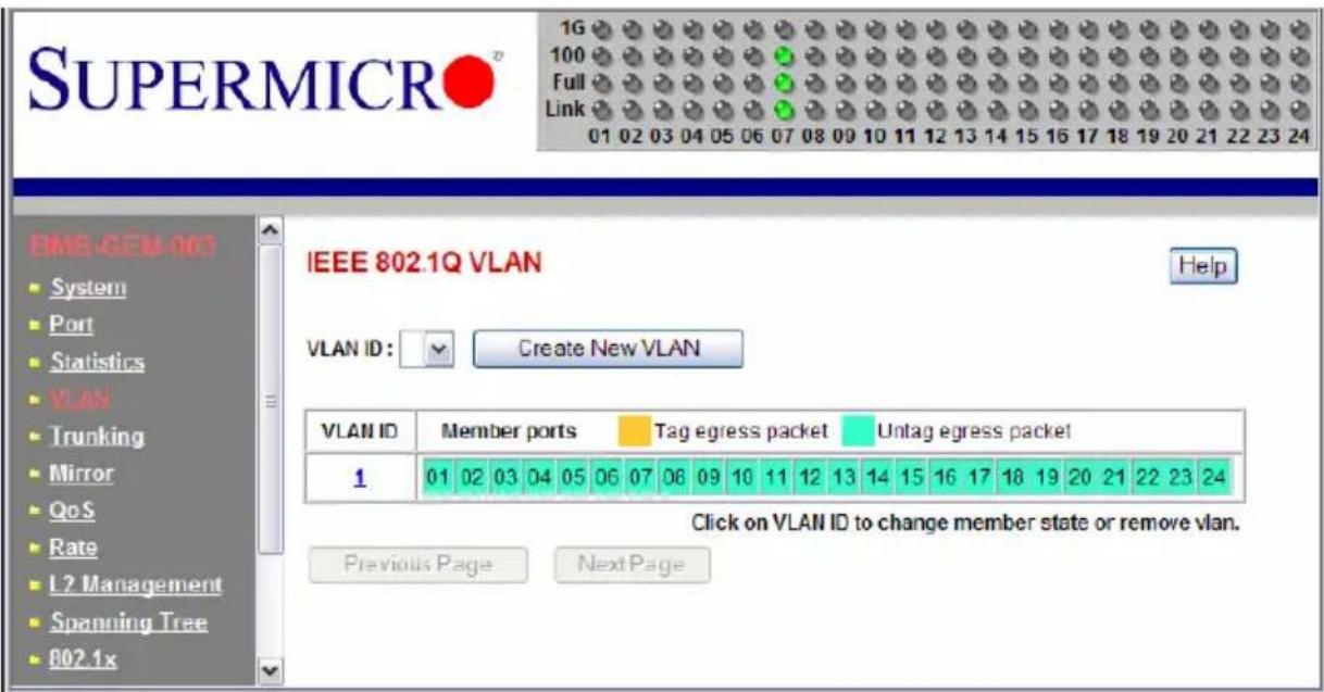
The switch supports an 802.1Q tagging VLAN. All packets entering the port of a switch only can be forwarded to a port that is a member of same VLAN. The ingress untagged frames are tagged by a per-port default tag (PVID). The forwarding decision is based on this assigned default PVID. If the ingress frames are 802.1Q tagged, the port won't alter the frames but will keep the frame's VLAN information intact. Tagged frames are forwarded according to a VID contained within the tag.
The switch also supports ingress filtering. The switch will examine the VLAN information in the incoming packets header to determine whether to drop or forward the packets. If the incoming frame has tagged VLAN information, the ingress port will check itself to see if it is a member of the tagged VLAN. If it is not, the frame will be dropped. If it's a member of the tagged VLAN, then it will check the destination port to see if it is a member of the tagged VLAN. If not, the frame is dropped. If the destination is a member
of the VLAN, the frame is forwarded to the destination port. If the incoming frame is not tagged with VLAN information, the ingress port will use PVID as the VLAN ID. If the destination port is not in the same VLAN, the frame is dropped.
The switch is initially configured to have one VLAN and its VID is 1. This VLAN is called the default VLAN. By default, all ports are initially assigned to the default VLAN.
Frames can not be forwarded across VLANs. Frames, whether they are unicast, multicast or broadcast, cannot flow from one VLAN to another VLAN unless there is a VLAN routing device to bridge them.
The switch also allows a user to configure the egress packets to either tagging or untagging. The untagging feature of 802.1Q VLAN allows a user to hook up the port to a legacy switch that doesn't recognize 802.1Q tagging header in the packet. Also, the tagging feature allows VLANs to span into multiple 802.1Q compliant switches through physical connections between switches.
6-4 Configuring a Static VLAN
The switch currently supports static VLANs only. To configure the VLAN, click on the VLAN folder at the left-hand side bar. The IEEE802.1Q VLAN screen should appear as shown in Figure 6-8. It lists the entire current VLAN configuration and also allows a user to create a new VLAN or modify port membership of a VLAN. The MEMBER PORTS indicates the number of member ports of the VLAN. There are two color symbols for each port to indicate tagging or untagging of packets egress from the port:
- Orange: Indicates a tagged egress packet
• Teal: Indicates an untagged egress packet
Creating a New VLAN
- Click on the C REATE NEW VLAN button. The screen as shown in Figure 6-9 should appear.
Figure 6-9. Creating a New VLAN
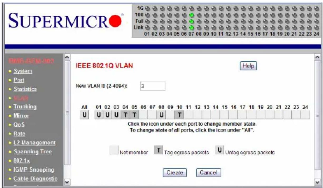
-
Assign a new VLAN ID, then click on the icon under each port to change the member state. There are three states to choose from: untag egress packets, tag egress packets and not member of a VLAN.
-
Click on the CREATE button to create the new VLAN. A new VLAN is shown in Figure 6-10.
Figure 6-10. New VLAN Screen
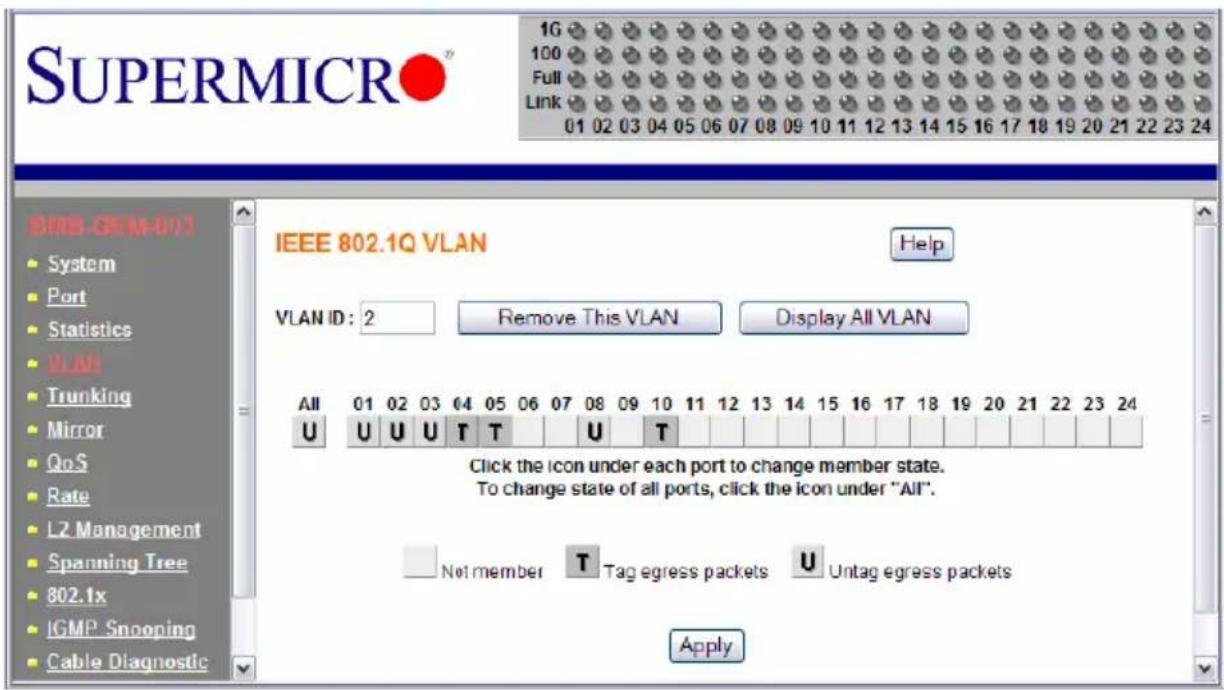
-
If you want to remove this VLAN, click on the R EMOVE THIS VLAN button. Click on DISPLAY ALL VLAN to list all of current VLAN configuration.
-
To change the port member state or remove a VLAN, select the VLAN either from the VLAN ID drop down menu or by clicking on the VLAN ID in the table in Figure 6-8. This screen shows the current member state of the selected VLAN. Users can modify the port member state, apply a change or remove the VLAN.
6-5 Trunking
Trunking aggregates multiple physical ports link into a single trunk to provide a single logical high-speed pipeline link. This is useful for switch-to-switch, switch-to-server and switch-to-router applications. The SuperMicro Gigabit Ethernet switch supports static type link aggregations. It uses a distribution algorithm to balance traffic between trunk members. This aggregates the bandwidth of the trunk. The switch considers a trunk as a single port entity regardless of the trunk composition.
The switch supports up to four separate trunks. Each trunk consists of 2 to 8 ports. A port in one trunk cannot simultaneously be in another trunk. Link aggregation is supported only on point-to-point links with the MAC operating in full duplex mode. All links in a trunk must operate at the same data rate.
The links within a trunk should have an equal amount of traffic to achieve maximum efficiency in a multiple-link trunk. Thus, some sort of load balancing among the links in a trunk is employed. One requirement for load balancing is that the frames being
transmitted must not be out of order. The switch performs load balancing based on a distribution algorithm that used the following information to assign conversation to ports:
- MAC source address
• MAC destination address
• MAC source address + destination address
The user can choose one of the distribution criteria from the configuration screen as shown in Figure 6-11.
Configuring the Trunk
- Click on T RUNKING folder on left-hand side bar to bring up the TRUNK SETTING screen, as shown in Figure 6-11.
Figure 6-11. Trunking Screen
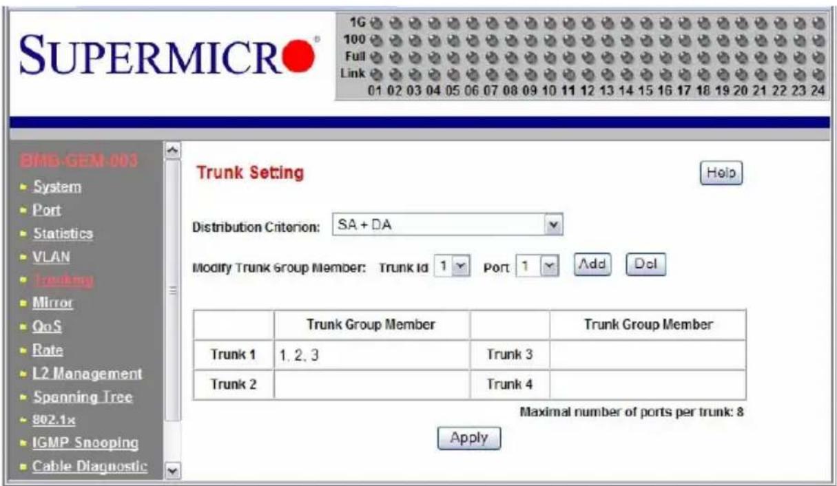
- Click on the T RUNK ID drop down list to select the trunk group to which you want to add port member.
- Click on the PORT drop down list to select the port number which you want to add to the selected trunk.
- Click on the A DD button to add it in. The port number should show up under the TRUNK GROUP MEMBER in the table. Click the DEL button to delete a port member from the selected trunk.
- Select one of the distribution criteria for the load balancing algorithm.
- Then, click A PPLY button to update and save to a new setting.
6-6 Mirroring
The switch supports port mirroring. A copy of the egress (transmit) data and the ingress (receive) data of the mirrored (monitored) port is sent to the mirroring (snooping) port. A user can attach a monitoring device to the mirroring port, such as a sniffer or an RMON probe to view the traffic at the mirrored port. This is useful for network monitoring and troubleshooting.
The switch allows for only one mirrored port at any given time. Port mirroring is independent from L2 switching. The receive mirrored port still forwards the frame to the mirroring port, even if the frame is eventually dropped.
To configuring port mirroring, click on the MIRROR folder in the left-hand side bar. The MIRROR SETTING screen should appear as in Figure 6-12.
Figure 6-12. Port Mirroring Screen
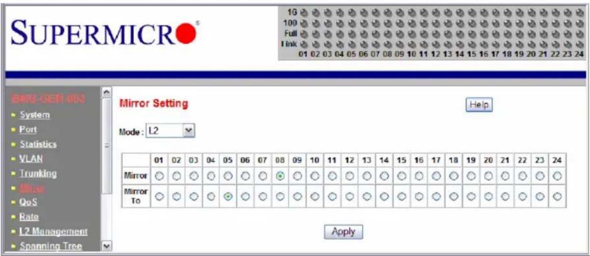
Table 6-4. Port Mirroring Screen Controls
| Control Description | |
| Mode This enables or disables mirroring. Select L2 to enable the mirroring. | |
| Mirror This specifies a Mirror port to which ingress and egress traffic will be mirrored. | |
| Mirror To This specifies the mirrored-to port. | |
| Apply This applies the mirror setting to the system. | |
6-7 Quality of Service
Quality of Service (QoS) helps a network user to reserve a guaranteed bandwidth for some critical application functions that require a high bandwidth and high priority. Applications such as video, audio streaming, VoIP and video conferencing must have a certain amount of bandwidth to maintain their operation correctly. QoS allows user to prioritize network traffic, thereby providing better services for those applications with a higher priority.
The switch supports 802.1p priority queuing QoS based on the priority bit in a frame's VLAN header. The 802.1p priority bit, if present in the frame, specifies the priority of the frame during forwarding. The 802.1p standard uses eight (0-7) priority levels for network traffic. Priority level 7 is the highest priority. Priority level 0 is the lowest level.
Priority Queues
Four priority queues are provided for each port. The priority queues are labeled from 3 to 0. Priority queue 3 has highest priority while queue 0 has lowest priority. The switch transmits the frames based on the priority of the queue, not the priority tag. Frames in a higher priority queue are served more often than frames in a lower priority queue.
User configurable mapping (priority queue assignment) between the eight 802.1p priority classes and the four priority queues is provided. If the incoming frame is untagged, the switch uses the priority field in the per-port default priority (configurable in the PORT folder) to assign a frame to a priority queue. If the incoming frame is tagged or priority-tagged, the switch uses the priority field in the incoming frame to assign the frame to a priority queue.
The scheduling for transmission among the four priority queues is accomplished by one of the two user-configurable schemes: strict (fixed) priority and weighted round-robin.
For strict priority based scheduling, the packets which were put in the higher priority queue are transmitted first. If there are multiple frames with different priority tags in the same priority queue, the frame with higher priority level is transmitted first. After all frames in the higher priority queue have been transmitted, the frames in the lower priority queue will start transmitting.
For the weighted round-robin based scheduling, the number of packets served in the priority queue is determined by the weight number. After those packets are transmitted, the service moves to transmit the packets in the next queue. Therefore, a higher priority queue should have a higher weight number than a lower priority queue. The weight number is from 1 to 15 for the switch. If each queue has same weight number, then each queue has an equal opportunity to transmit frames just like in round-robin queuing.
To configure the QoS, click the QoS folder on the left-hand side bar. It should display as shown in Figure 6-13.
The QOS SETTING sets the priority relationship between the four queues, selects the scheduling method for those queues, associates packets of specific priorities to specific queues, and specifies a “weight” for each queue.
Figure 6-13. QoS Setting Screen
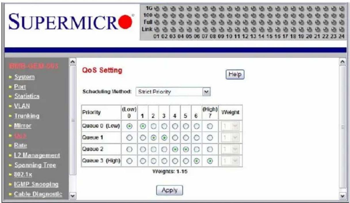
Table 6-5. QoS Setting Screen Controls
| Control Description | |
| Scheduling Method | This specifies one of the two scheduling methods (Strict and Weighted Round-Robin) for the queues. |
| Queue [0:3] | Queue [0:3] prioritizes the four queues. Queue 0 is the lowest priority queue and queue 3 is the highest priority queue. Packets in queue 3 are served more often than packets in queue 0. |
| Priority | This indicates packet priority. This value is retrieved from the priority tag field, with values from 0 to 7. 0 indicates the lowest priority and 7 indicates the highest priority. Click on the radio button to send packets of a specific priority to a particular queue. |
| Weight | This indicates the weight (number of packets) to be served in the queue before moving to serve the next queue. A high priority queue should have a higher weight than a low-priority queue. |
6-8 Rate Control
The switch supports per-port rate control. When the data rate of the incoming frame for a particular port exceeds a selected rate, the excess frame traffic is subject to packet drops or flow control, depending on the per-port flow control configuration in the PORT folder. If the flow control of a particular port is enabled, then the switch uses flow control to inhibit any excess traffic. If the flow control is disabled, the excess frames will be dropped.
To configure the ingress rate limit for a port, click on RATE in the left-hand side bar. The RATE LIMIT AND STORM CONTROL screen appears as Figure 6-14.
Figure 6-14. Rate Limit and Storm Control Screen
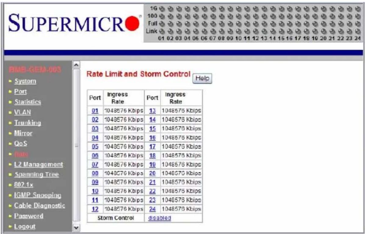
The screen shows the Ingress Rate (in kilobits per sec) for all ports. Click on the port number to control the ingress rates for the port. There are eight different levels to select: no limit (1Gbps), 256Kbps, 1Mbps, 4Mbps, 16Mbps, 64Mbps, 128Mbps or 512Mbps. The STORM CONTROL indicates the current status of storm control.
A traffic storm happens when broadcast, multicast or unknown unicast packets flood the network, which will degrade the network performance. The storm control monitors the traffic of an incoming particular type of frame (configured by the user) and limits traffic to a user configurable rate level (threshold). The storm rate threshold is counted in number of packets per second (pps). If the traffic of a particular frame type exceeds the threshold during one second, all the rest of that type of frame will be dropped before the end of that second.
The switch provides configuration to assign storm control type and rate limitations to the entire system.
To configure storm control, click STORM CONTROL link in the RATE LIMIT AND STORM CONTROL screen (Figure 6-14). The STORM CONTROL screen appears as shown in Figure 6-15.
Figure 6-15. Storm Control Screen
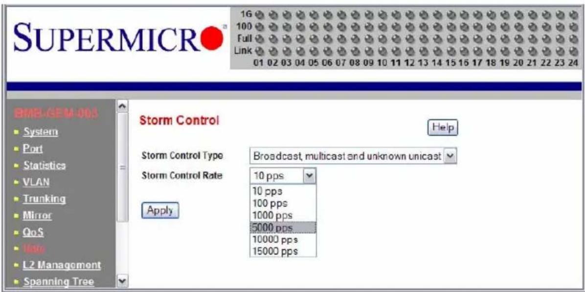
Table 6-6. Storm Control Screen Controls
| Control Description | |
| Storm Control Type | This selects the type of the packet storm. The figure below shows all available options: Broadcast only, Broadcast and multicast, Broadcast unknown unicast and Broadcast, multicast, and unknown unicast. |
| Storm Control Rate | This selects a rate (packets-per-second) for storm control. The figure below shows all available options: 10 pps 100 pps 1000 pps 5000 pps 10000 pps and 15000 pps. |
6-9 L2 Management
L2 management provides a way to add, delete, and look up MAC addresses in the L2 address table. The switch supports 8192 L2 address table entries, each specifying a MAC address, VLAN ID, destination port number, trunk ID and Rtag. The switch supports store-and-forward mode switching.
After a frame is received, its source MAC address (MACSA) and destination MAC address (MACDA) are retrieved. Depending on the port state, the MACSA and port number may be used to dynamically update the L2 address table. The MACDA may be used to determine the frame's destination port. User can also statically add a MAC address to the L2 address table.
To add a static entry into the L2 ADDRESS table, click on the ADD link on the L2 ADDRESS MANAGEMENT screen as shown in Figure 6-16.
Figure 6-16. L2 Management Screen
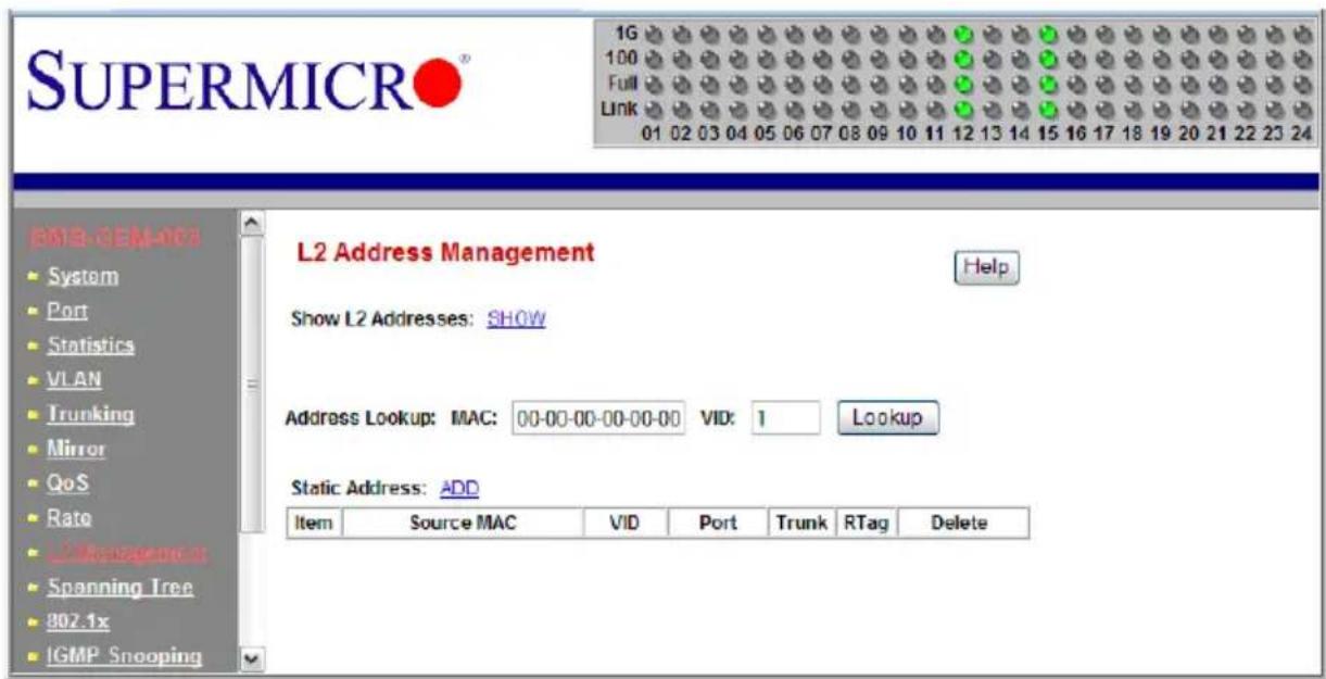
To remove the specified static MAC address from the table, click the DELETE link for that MAC address as shown in Figure 6-17 when there are static entries in the table.
To search for a MAC address to see if it exists in the table or not, enter the MAC ADDRESS and VID, then click on LOOKUP button. If the MAC address is in L2 ADDRESS table, whether it is a static or a dynamic MAC address, the result will be displayed.
To show all of MAC address in the L2 table, click the SHOW link next to SHOW L2 ADDRESSES.
Figure 6-17. L2 Management: Current Entries Screen
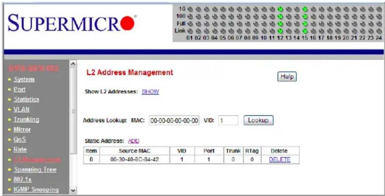
6-10 Spanning Tree
The Spanning Tree Protocol (STP) helps to detect and prevents loops from occurring on a switched or bridged network. When multiple paths exist on a network, STP will configure the network to use the most efficient path between network devices. All other paths are forced into a blocked standby state. If the active path fails, then STP will automatically select another path to become the active path on the network to sustain normal network operations. An active path is selected by comparing path costs defined on each path. The path with the lowest cost will be selected.
The switch supports IEEE802.1d Spanning Tree Protocol and IEEE802.1w Rapid Spanning Tree Protocol (RSTP). The Rapid Spanning Tree Protocol significantly reduces the convergence time by assigning port roles and by determining the active topology. A reconfiguration of the spanning tree can occur in less than one second. The RSTP is backward compatible with legacy devices running IEEE802.1d STP and serves as an STP device when an STP device is present in the network.
Bridge Protocol Data Unit (BPDU)
The spanning tree is built by obtaining switch information by exchanging Bridge Protocol Data Unit (BPDU) packets among the participating switches. When RSTP is enabled for a switch, it will generate a BPDU and periodically forward it out through each port on the switch. The interval is configurable through the Hello Time, which is set to a two second default. This enables the switch to keep track of network topology changes and enable or disable ports as required.
The BPDU contains the information about the transmitting switch and its ports including MAC address, bridge priority, port priority and port path cost. The BPDU packet is sent out by using the unique MAC address of the port itself as a source address, and the destination address of the STP multicast address 01:80:C2:00:00:00.
There are three types of BPDUs:
- Configuration BPDU – for spanning tree computation
- Topology Change Notification (TCN) BPDU – announces changes in network topology.
• Topology Change Notification Acknowledge (TCA) BPDU
The major operation of the spanning tree protocol includes a root bridge election, finding paths to a root bridge, determining the least cost path to root and disabling all other root paths. When a RSTP enabled switch is turned on, it automatically assumes that it is the root bridge in the spanning tree. The software in the switch will elect a switch as the root bridge based on the Bridge ID in the received BPDU. The Bridge ID is an 8-byte field which combines a high order two-byte bridge priority number and a lower order six-byte switch MAC address. The switch with the lowest Bridge ID will be elected as the root bridge.
All RSTP participating switches will use an algorithm to determine how close they are to the root bridge, which is known as Path Cost. The path with lowest cost will be selected as the active path. All others will be blocked (standby). TCN packets are injected into the network by a non-root switch and propagated to the root. Upon receipt of the TCN, the
root switch will set a Topology Change flag in its normal BPDUs. This flag is propagated to all other switches to instruct them to rapidly age out their forwarding table entries.
Port Transition State
When a device is connected to an RTSP or STP enabled switch port for the first time, it will not immediately start to forward data. Instead, it will go through a number of states while it processes BPDUs and determines the network topology.
There are five port states in the legacy 802.1d STP: disabled, blocking, listening, learning and forwarding. The RSTP combines the disabled, blocking and listening states used in 802.1d STP and creates a single state: Discarding. Table 6-7 lists the comparison of port states between 802.1d STP and 802.1w RSTP.
Table 6-7. Comparison of Port States
| State Displayed 802.1d STP | 802.1w RSTP | |
| Discarding Disabled Discarding | ||
| Discarding Blocking Discarding | ||
| Discarding Listening Discarding | ||
| Learning Learning Learning | ||
| Forwarding Forwarding Forwarding |
RSTP Port Roles
RSTP will assign port roles for each port during the process receiving the BPDUs. Based on its port role, a port can either send or receive BPDUs and forward or block data traffic.
- Root – the port that provides the lowest cost path when the switch forwards packets to the root switch.
- Designated – the port closest to the root switch and forwarding traffic toward the root switch and sending BPDUs in a link segment. Each designated port is in a forwarding state.
- Alternate – this port provides an alternate path to the root bridge. This path is different than using the root port. The alternate port is in a blocking state.
- Backup – the port provides a backup/redundant path to a link segment to which another switch port already connects. This is a special case when two or more ports of the same switch are connected together.
- Disabled - Not a strictly part of RSTP, a network administrator can manually disable a port.
To configure the RAPID SPANNING TREE, click the SPANNING TREE folder on the left-hand side bar. There are two portions to configure: RSTP SWITCH SETTINGS and RSTP PORT SETTINGS, as shown in the RAPID SPANNING TREE screen (Figure 6-18).
Figure 6-18. Rapid Spanning Tree Screen
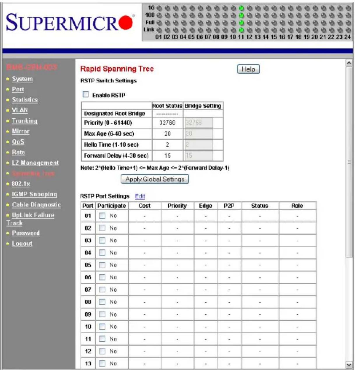
The RSTP SWITCH SETTINGS allows the user to control RSTP parameters from the bridge point-of-view. ROOT STATUS shows status of the root bridge. BRIDGE SETTING shows the current bridge setup.
To turn on the Rapid Spanning Tree Protocol (RSTP), check on the ENABLE RSTP dialog box and click on the APPLY GLOBAL SETTINGS button.
Root Status
The settings for ROOT STATUS are shown below:
- Designated Root Bridge – The bridge identifier of the root of the spanning tree is determined by the RSTP protocol as executed by this node. The bridge identifier value is used as the Root Identifier parameter in all configuration Bridge PDUs originated by this node.
- Max Age – This indicates the maximum age of the root bridge. This is the maximum age of spanning tree protocol information learned from the network on any port before it is discarded, in units of hundredths of a second. This is the actual value that this bridge is currently using.
- Hello Time – This indicates the amount of hello time of the root bridge. Hello time is the amount of time between the transmission of configuration Bridge PDUs by this node on any port when it is the root of the spanning tree or trying to become so, in units of hundredths of a second.
- Forward Delay – This indicates the amount of forward delay of the root bridge. Forward delay is a time value, measured in units of hundredths of a second, which controls how fast a port changes its state. The value determines how long the port stays in each of the listening and learning states, which precede the forward state. This value is also used to age all dynamic entries in the forwarding databases when a topology change has been detected and is underway.
Bridge Setting
Settings for Bridge Setting are shown below:
- Priority – This configures the priority of the current bridge.
- Max Age – This configures the maximum age of the current bridge. This is the maximum age of spanning tree protocol information learned from the network on any port before it is discarded, in units of hundredths of a second. This is the actual value that this bridge is currently using.
- Hello Time – This indicates the amount of hello time of the current bridge. Hello time is the amount of time between the transmission of configuration Bridge PDUs by this node on any port when it is the root of the spanning tree or trying to become so, in units of hundredths of a second.
- Forward Delay – This indicates the amount of forward delay of the current bridge. Forward delay is a time value, measured in units of hundredths of a second, which controls how fast a port changes its state. This value determines how long the port stays in each of the listening and learning states, which precede the forward state. This value is also used to age all dynamic entries in the forwarding databases when a topology change has been detected and is underway.
RSTP Port Settings
These settings control and monitor the port-based spanning tree status.
- Participate – This specifies if the RSTP is enabled or not for the selected port.
- Cost – Displays the cost of this port. “Cost” means the contribution of this port to the path cost of paths towards the spanning tree root which include this port.
- Priority – Displays the priority of this port. This is the value of the priority field contained in the first octet of the Port ID.
- Edge – This indicates if this port is the edge port. Once configured as an edge port, the port immediately transitions to the forwarding state. It is available only when the port is directly connected to an end terminal (or a file server) that has no influence on the spanning tree configuration. Since ports 11 to 24 are connected to blade server NIC ports, all of those ports can be configured as an Edge port.
- P2P – This indicates if this port is a point-to-point link. If you connect a port to another port though a point-to-point link and the local port becomes a designated port, it negotiates a rapid transition with the other port to ensure a loop-free topology.
- Status – This displays the RSTP port status.
- Role – This displays the role of this port.
To modify the PORT SETTINGS for each port, click on the EDIT link next to PORT SETTING. The RAPID SPANNING TREE - PORT SETTINGS screen (Figure 6-19) will appear.
Figure 6-19. Rapid Spanning Tree Port Settings
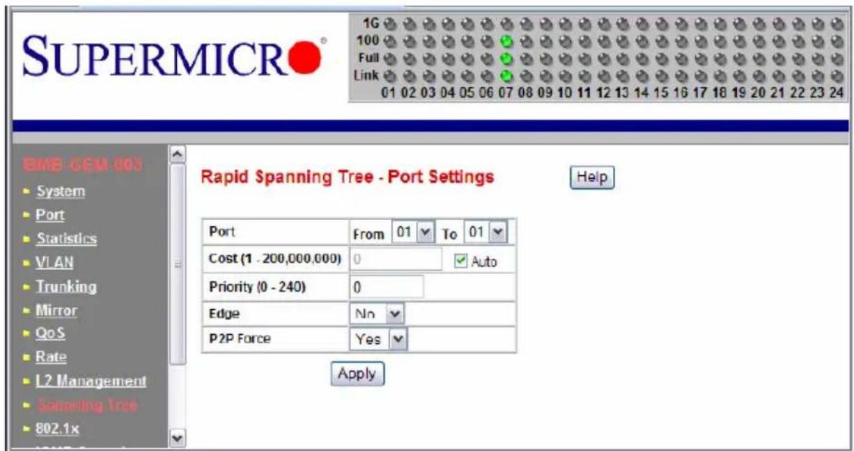
Select a group of port numbers that you want to configure. Setting the COST to zero or checking AUTO will automatically set the default value depending on the link speed. The default cost is 20000 for a Gigabit port and is 100000 for a 100Mbps port.
6-11 IEEE 802.1x
IEEE 802.1x is a client-server based access control and authentication protocol that restricts unauthorized user devices from connecting to the LAN through publicly accessible ports. This port-based access control is accomplished by using a RADIUS server that is connected to a gigabit switch management port to authenticate client users trying to access a network through the switch. The gigabit switch will relay Extensible Authentication Protocol over LAN (EAPoL) packets between the user client and the RADIUS server. The 802.1x protocol consists of three components: client, authenticator and authentication server.
The Authentication Server is a remote device that runs the RADIUS server program (Windows 2000/2003 IAS ^™ , freeRADIUS ^™ from open source). The role of the Authentication Server is to certify the identity of a client attempting to access the network. By exchanging secure information between the RADIUS server and the client through EAPoL packets, the Authentication Server will inform the switch whether or not the client is granted access to the LAN through the connected port.
The client is a workstation that wishes to access the network through a connected switch port. All workstations have to run a program (supplicant) that is compliant with the 802.1x protocol. Microsoft Windows XP ^™ and Vista ^™ should have this. A user can also install another third party package, such as Odyssey ^® from Funk Software ^® .
When the GLOBAL RADIUS SETTING and SET STATUS of an individual port are enabled, that port will initially be placed into an unauthorized state. The client will initiate negotiations by sending an EAPOL START packet.
There are several EAP authentication methods available in Microsoft Windows XP, such as EAP-MD5, EAP-TLS and EAP-PEAP. Currently, the gigabit switch only supports EAP-MD5 for 802.1x authentication.
- PEAP-MS-CHAP v2 uses password-based credentials and requires computer certificates on the RADIUS servers.
- EAP-TLS uses certificate-based credentials and requires user and computer certificates on the wire's client computers and computer certificates on the RADIUS servers.
- EAP-MD5 (Message Digest 5) Challenge Handshake Authentication Protocol (MD5 CHAP), which uses passwords.
Wiring for 802.1x
The EAPOL packets are handled by a management processor in the switch. The processor communicates with the outside world through three ports. Two ports (eth0 and eth1) are connected to the CMM module's Ethernet port and the third port (eth2) is connected to all 24 switching ports. Only one port is enabled at any time. The regular configuration setup switch is managed through the CMM Ethernet port. Thus, for regular deployment, the RADIUS server should be located where it can be reached from the CMM Ethernet port.
802.1x Configuration
Figure 6-20. 802.1x Configuration Screen
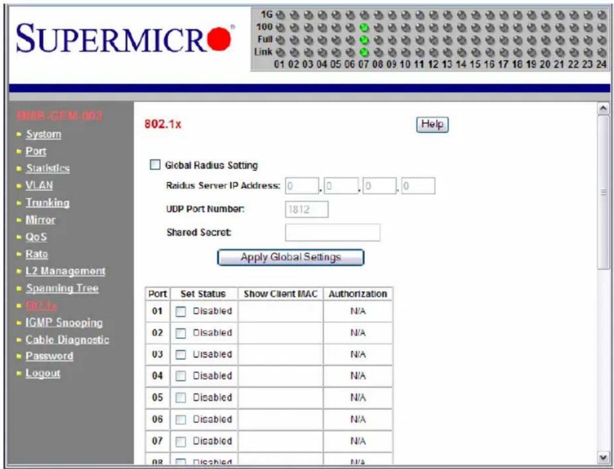
To configure 802.1x port based access control, click on the 802.1x folder in the left-hand side bar. The 802.1x configuration should display as shown in Figure 6-20. Check the GLOBAL RADIUS SETTING dialog box to enable 802.1x port based access control.
- Radius Server IP Address – This indicates the IP address of the RADIUS server.
- UDP Port Number – This specifies the UDP port number of the EAPOL control frame. 1812 is the default UDP port number. If the RADIUS server can't recognize them, other numbers can be used.
- Shared Secret – This is a 16-character string used by the RADIUS server as a password to identify EAPOL control frames.
The PORT AUTHENTICATION SETTINGS allows you to enable or disable authentication for individual ports. It also displays the results when a port is enabled for authentication.
- Set Status – This enables or disables port authentication. ENABLE PORT AUTHENTICATION STATUS means a port should be authorized by a RADIUS server to forward traffic. No traffic is forwarded if it is unauthorized. No authentication process is required for those ports in disabled status; traffic can be forwarded normally.
-
Show Client MAC – This displays the last client in the MAC address who sent out the EAPOL control frame of the port.
-
Authorization – This displays the authentication status of an enabled port. It includes the following status:
-
In Progress – This indicates that the authentication is still in progress. Traffic is not forwarded before authentication is verified.
-
Yes indicates the port access is authorized.
- No indicates the port access is not authorized.
- N/A means no authentication required.
6-12 IGMP Snooping
IP multicast is often used to distribute video/audio multimedia data over the network. The layer 2 switch will flood multicast frames to all of ports of switch, which wastes a lot of unnecessary network bandwidth. IGMP is a standard defined in RFC1112 for IGMPv1 and in RFC2236 for IGMPv2. IGMP specifies how a host can register a router in order to receive specific multicast traffic. A layer 3 switch usually supports Internet Group Management Protocol (IGMP) to manage multicast groups by sending and processing IGMP packets. To prevent the unnecessary flooding, the gigabit layer 2 switch can enable the IGMP snooping function to control how IP multicast packets are forwarded to required ports by monitoring IGMP queries and response packets generated by layer 3 switches or the IGMP querier.
Currently, the gigabit switch supports IGMP snooping for IGMP v1/v2 packets. In the real network setup, the switch is seated between the Multicast Router/Server and the host. The Multicast Router/Server will periodically send an IGMP v2 query packet and the host will respond with an IGMP v2 report packet if the host is in the same multicast group. When the host wants to go away, it can send an IGMP v2 Leave packet. The switch will remove the connected port number from the multicast group entry of a table. If the host is just silently removed, then the switch will clean it from table when the timer expires.
Figure 6-21 shows the IGMP SNOOPING configuration screen. Table 6-8 describes each configuration item.
Figure 6-21. IGMP Snooping Screen
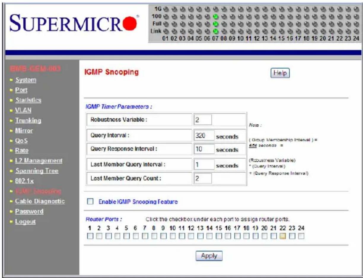
Table 6-8. IGMP Snooping Screen Controls
| Control Description | |
| Robustness Variable | This allows tuning for the expected packet loss on a subnet. If a subnet is expected to be lossy, the Robustness Variable may be increased. IGMP is robust to (Robustness Variable-1) packet losses. The Robustness Variable must not be 0, and should not be 1. The default value is 2. |
| Query Interval | This is the interval between general queries sent by the querier. The default interval is 125 seconds. By varying the [Query Interval], an administrator may tune the number of IGMP messages on the subnet; larger values cause IGMP queries to be sent less often. |
| Query Response Interval | This is the maximum response time inserted into the periodic general queries. The default value is 100 (10 seconds) By varying the query response interval, an administrator can tune the bursting of IGMP messages on the subnet; larger values make the traffic less bursty, as host responses are spread out over a larger interval. The number of seconds represented by the query response interval must be less than the query interval. |
| Last Member Query Interval | This is the maximum response time inserted into group-specific queries sent in response to Leave Group messages, and is also the amount of time between group-specific query messages. The default value is 10 (1 second). This value may be tuned to modify the “leave latency” of the network. A reduced value results in reduced time to detect the loss of the last member of a group. |
| Last Member Query Count | This is the number of Group-Specific Queries sent before the router assumes there are no local members. Default: the Robustness Variable. |
| Enable IGMP Snooping Feature | This is used to enable the IGMP snooping feature. |
| Router Ports This specifies ports to which IGMP routers were connected. | |
6-13 SNMP
The SNMP agent in the gigabit switch supports SNMP v1 and v2c. It also supports the following MIB:
- RFC1213 MIBII with standard sets which include system, interfaces, IP, ICMP, TCP, UDP, Dot3, and SNMP.
• RFC2011 SNMPv2 MIB for IP using SMIv2
• RFC2665 EtherLike MIB
6-14 UpLink Failure Tracking (ULFT)
Uplink Failure Tracking (ULFT) feature is provided to support network adapter Teaming (Windows Systems) or Channel Bonding (Linux Systems) on SuperBlade servers.
Installing two GbE switch modules can have additional connectivity to allow increased network bandwidth, redundancy, and/or fault tolerance. The connection between internal ports of the switch and each LAN port of the server blades is hardwired through the middle plane. The link will not be dropped unless either switch's internal port or the server blade's LAN port fails.
By enabling the ULFT feature with proper pair configuration, a failover event can be triggered in the Teaming or Channel Bonding program when all of a switch's external uplink member ports fail. The switch automatically enables the internal downlink ports once one of the uplink ports in the configured pair returns to service.

NOTE: By default, the switch's ULFT feature is disabled. The link status on the external uplink ports does not affect the link status of internal downlink ports.
To use ULFT, you must configure a Failure Tracking Pair and enable the ULFT feature. A Failure Tracking Pair consists of uplink and downlink ports. The uplink tracking member contains at least one of the external ports: port 1 to port 10. The downlink tracking member contains at least one of the internal ports: port 11 to port 24.
If Trunking is enabled on the external uplink ports, then all of the trunk member ports should be configured as uplink members of a tracking pair. The link to the configured internal downlink member ports is disabled when all of the trunking uplink member ports fail. Figure 6-22 shows the UPLINK FAILURE TRACKING CONFIGURATION screen. Table 6-9 describes each configuration item.
For example, if your SuperBlade has two blade servers installed on slot 1 and slot 3, then each blade has two LAN ports, one connected to the internal port of the upper GbE switch and the other one connected to the internal port of the bottom GbE switch. To implement switch redundancy, you need to have two GbE switches installed. Each of these GbE switches should enable the UpLink Failure Tracking feature and have the exact same proper configuration as shown in Figure 6-22.
The pair configuration in this example defines the ULFT for blade 1 and blade 3. The external port 5 of each switch is connected to an external third party switch through an Ethernet cable. This assumes that the Network Adapter Teaming or Channel Bonding has a proper configuration and is running on each of the blades.
If one of the external Ethernet cables is broken or the third party switch port to which the cable connects fails, then one of the SuperBlade GbE switches will detect a link drop on its external port 5 and turn down the link on its internal ports 11 and 13. The Teaming or Channel Bonding software running on both of these blades then detects a link drop on one of its LAN ports and switches to another LAN port automatically. This allows network traffic to go through another GbE switch.
Notes
Note that ULTF will only drop an internal link from the blade to the switch if all of the (external) uplinks defined for that blade have failed (or been disabled) on that switch. As long as one or more of uplinks on a particular switch (that have been defined for a particular downlink) is active, the blade and switch will keep the internal link active.
Figure 6-22. Uplink Failure Tracking Configuration Screen
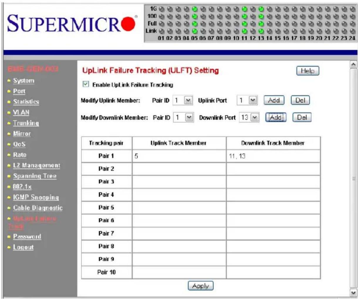
Table 6-9. Uplink Failure Tracking Configuration Screen Controls
| Control Description | |
| Enable UpLink Failure Tracking | Enables/Disables the UPLINK FAILURE TRACKING feature. |
| Modify Uplink Member | Select the pair ID and uplink port number to add/delete to/from uplink member of a pair. |
| Modify Downlink Member | Select the pair ID and downlink port number to add/delete to/from downlink member of a pair. |
| Uplink Track Member This column defines member ports of an uplink in a ULFT pair. | |
| Downlink Track Member This column defines member ports of a downlink in a ULFT pair. | |
Chapter 7 1/10-Gb Ethernet Switch Firmware
This chapter is provided to help you quickly get started in using the firmware for your SBM-GEM-X2C/+ 1/10 Gigabit Ethernet switch module, using the web-based management GUI tool.

NOTE: The 1/10 Gigabit Ethernet switch module is available in two versions:
• SBM-GEM-X2C which supports 10 or 14 blade enclosure systems
- SBM-GEM-X2C+ which supports twin-blade (20 blade) systems
Except for the maximum number of blades supported, these two products are identical. The “SBM-GEM-X2C/+” part number is therefore used throughout the rest of this manual to refer to features and operational characteristics of both versions.

NOTE: See the SM-CLI Guide included on your SuperBlade Switch System CD-ROM for further information on the 1/10 Gigabit Ethernet switch firmware and its controls using the CLI.
7-1 Overview
The Supermicro switch utility for the 1/10 Gigabit Ethernet switch modules provides a web-based interface for managing layer2 and layer3 switching at wire speed for constructing a switched/routed network. This interface provides both a bridging functionality and advanced features such as link aggregation, Dynamic VLAN/Dynamic Multicast, IGMP Snooping and Network Access Control. This web-based interface also comes with several Layer3 features as well (such as wire speed routing, Differentiated services, multicast routing and so on).
The Supermicro Switch firmware is implemented using open sources from OpenSSL, OpenSSH and other open source communities and is configured using web browsers such as Internet Explorer.
The utility starts with a default IP address, which is also the management IP address. This IP address is essentially provided for remote management of this switch. For managing the switch through web browsers, type in the default IP address in your browser's web address in order to start accessing the switch.
For example, if the management IP address of the switch is 192.168.1.1, the switch can be accessed through the Web browser by typing http://192.168.1.1 in the address space of the web browser.
The default management IP address for Supermicro Switch products is 192.168.100.102. This default IP address can be changed in the SYSTEM SETTINGS page in the System Management section.
The management interface for the SBM-GEM-X2C/+ is the same as that for the Supermicro standalone SSE-G24-TG4 and SSE-G48-TG4 1/10 Gigabit Ethernet switch modules.
For the SSE-G48-TG4 and SSE-G24-TF4 switches, you can connect to any of the front panel 1G ports or back panel 10G ports to manage the switch with the default management IP. These switches will create VLAN 1 by default with this IP address, including all 1G and 10G ports.
The SBM-GEM-X2C/+ blade switch can be managed with the default IP through CMM Ethernet connections, since the internal management Ethernet ports of the SBM-GEM-X2C/+ switch are connected with CMM Ethernet ports internally. If you prefer to manage the SBM-GEM-X2C/+ switch through front panel ports or through any other switching ports, then you can assign the desired management IP address to VLAN 1. Alternatively, you can create any VLAN and manage the switch through switching ports. Here the term switching ports refer to all internal and external 1G and 10G ports of the switch.
Nomenclature
The following nomenclature applies to screens found in this chapter:
- Port */* – This indicates the stacking ID number, port number
- Port Number GB */* – This is for an internal port
- Port Number Ext */* – This is for an external port.
7-2 Login
Figure 7-1. Login Page

The initial login page (Figure 7-1) is used to login to the Supermicro Switch web-based management utility for 10-Gbps switches. To login, enter your User Name and Password in the fields provided and press the LOGIN button.
This User Name and Password are both used for accessing the switch through the web for switch configuration. The entered user name and password are validated at the switch end.
After logging in, you will be taken to the HOME page of the utility. See Section 7-3: Home Page on page 7-3 for further details.
7-3 Home Page
The HOME page (Figure 7-2) contains links and menus for going to all other control pages in the Supermicro Switch web-based interface utility. A list of controls for this page is shown in Table 7-1. The basic page structure of the HOME page is duplicated for all subsequent sub-pages of the Supermicro Switch web-based interface utility.
Figure 7-2. Home Page
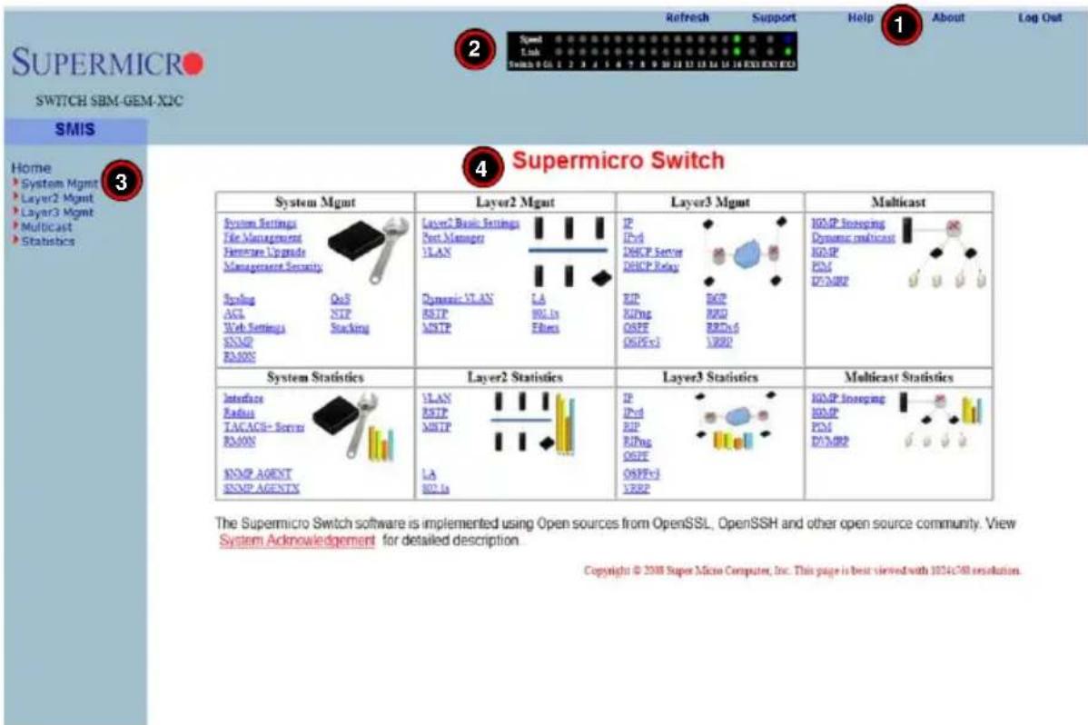
Table 7-1. Home Page Controls and Components
| Number | Name Description | |
| 1 Top Page | Links | The Top Page Links are present both on the Home page and all other pages accessed and contain links to support pages or additional controls for all pages viewed with the Web Management Utility. See "Top Page Links" below for further details. |
| 2 Top LED | Display | This section of the screen provides an overview port status for the switch. See "Top Page Links" for further details. |
Table 7-1. Home Page Controls and Components
| Number | Name Description | |
| 3 Left Side | Tree | The Left Side Tree contains an expandable list of links for you to use to get to other management pages. All configuration pages contain this navigation tree. |
| 4 | Middle Configuration Links Table | Each configuration page contains its own links and controls |
The HOME page is displayed on successful validation of the user name and password. The information in this page presents a brief overview of the switch web-based management utility. See Figure 7-3, Figure 7-4 and Figure 7-5 for different views of the Home page for each of Supermico's 10-Gbps switches.
Figure 7-3. SBM-GEM-X2C/+ Home Page
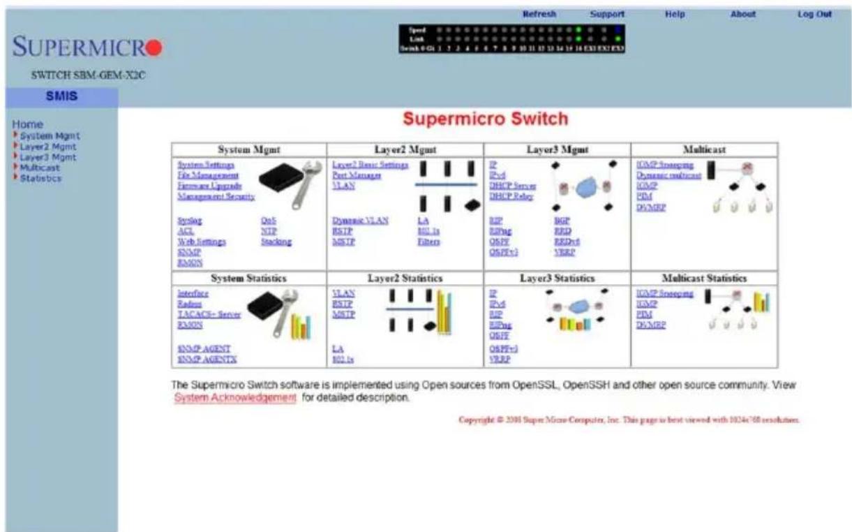
Figure 7-4. SSE-G24-TG4 Home Page
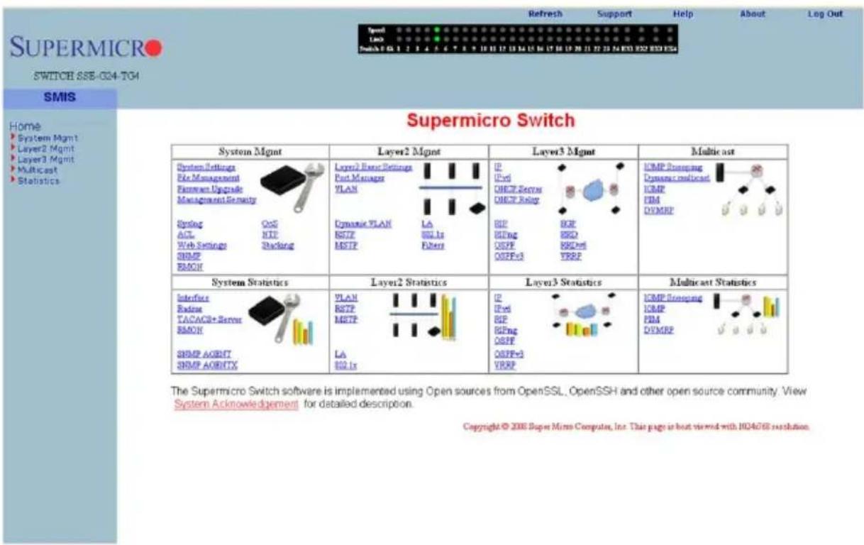
Figure 7-5. SSE-G48-TG4 Home Page
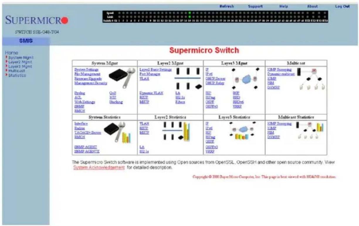
Top Page Links
On the top of all pages of the web-based management utility you can find the following PAGE HEADER links:
- Refresh – Click this link to refresh the contents of the page. Unlike the browser refresh button, this link refreshes only the contents of the middle of the page which has the active data.
- Support – Click this link to get technical support for Supermicro Products.
- Help – Click on this link to open a context specific help page that covers all the items on the page being viewed.
- About – Click this link to get additional information about the web-based management utility, the switch and also the versions supported.
- Log Out – Click this link to log out of the web session and go back to the Login page.
Top LED Display
This part of the screen displays the Port Status, Speed and Link Status for every port of the switch.
Since the number of ports is different in SBM-GEM-X2C/+, SSE-G24-TG4 and SSE-G48-TG4 switches, this display displays a different number of ports for each when the Web Management Utility is run:
- For the SBM-GEM-X2C switch, it displays sixteen Gigabit Ethernet (Gi) ports and three 10-Gigabit Ethernet (Ex - Extreme Ethernet) ports.
- For the SBM-GEM-X2C+ switch, it displays twenty-two Gigabit Ethernet (Gi) ports and three 10-Gigabit Ethernet (Ex - Extreme Ethernet) ports.
- For the SSE-G24-TG4 switch, it displays twenty four Gi ports and four Ex ports.
- For the SSE-G48-TG4 switch, it displays forty eight Gi ports and four Ex ports.
Note that Ex ports configured as stacking ports will not be displayed.
In stacking, the Switch Identifier will be displayed on top of this LED display. This allows you to select a stack member switch of interest, and to view the LED display for the corresponding switch.
For Link, a green light corresponding to a number indicates that that numbered port is up, whereas a red light corresponding to a number indicates that this port is down.
Left Side Tree
The tree display on the left side of the page provides quick access to the configuration pages. This tree is organized based on the features supported in the switch. The main features are categorized in the following groups.
- System Management - System based configurations
- Layer 2 Management - Layer 2 Protocols including VLAN, RSTP, MSTP, ...
-
Layer 3 Management - Layer 3 Protocols including - IP, RIP, OSPF, ....
-
Multicast Management - Multicast Protocols including IGMP, PIM, ...
• Statistics - Statistics and Counters for all the features.
This tree is displayed on the left navigation pane on all configuration pages. This makes it easier for you to choose any configuration page directly without going back to the home page every time. To go to one of a MANAGEMENT page's sub-pages, click on the symbol to expand the list.
Middle Configuration Link Table
This section of the page displays a table of links to all major configurations. This table provides links similar to the Left Side Tree links. The configuration links are categorized based on features of the switch.
7-4 System Management Page
Figure 7-6. System Management Page
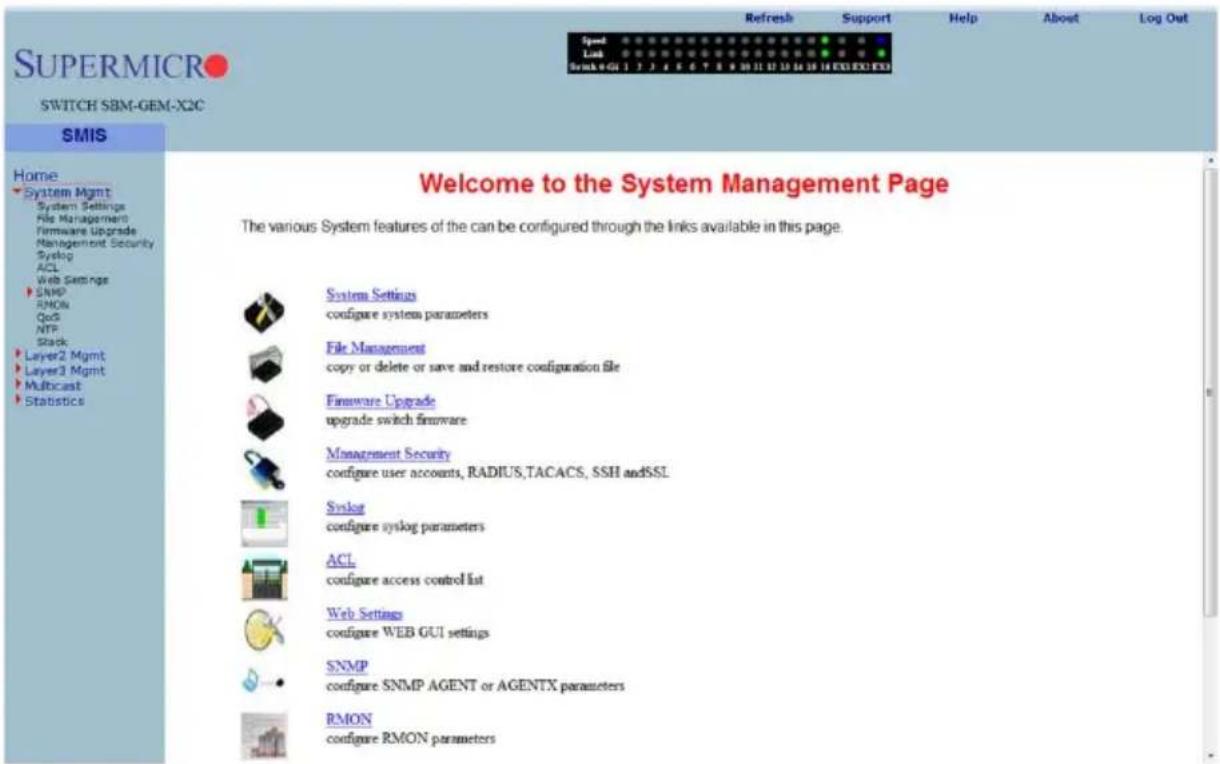
The SYSTEM MANAGEMENT page (Figure 7-6) contains the following links:
- "System Settings" on page 7-9
• "System Version" on page 7-11 - "File Management" on page 7-12
• "Firmware Upgrade" on page 7-14
• "Management Security" on page 7-15 - "Syslog" on page 7-24
-
"ACL" on page 7-26
-
"WEBGUI Settings" on page 7-30
- "SNMP" on page 7-31
- "RMON" on page 7-42
• "QoS" on page 7-47
• "NTP Settings" on page 7-52 - "Stack" on page 7-53
System Settings
The following pages can be accessed through the System Settings link:
- "System Settings" on page 7-9
• "System Version" on page 7-11
System Settings
Figure 7-7. System Settings Page
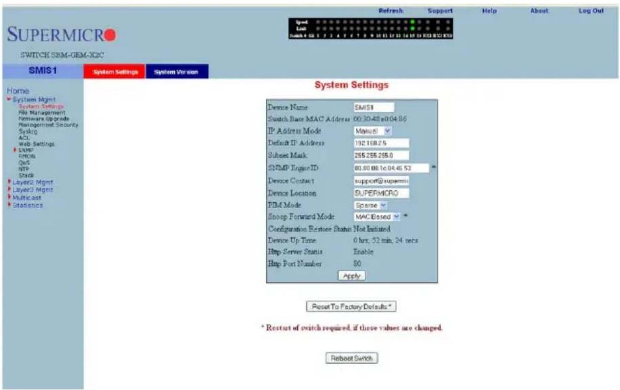
Clicking the SYSTEM INFORMATION tab brings up the SYSTEM SETTINGS page (Figure 7-7). This page provides system related information and also helps you configure system specific parameters. Table 7-2 lists the parameters found on this page.
Table 7-2. System Information Page Parameters
| Parameter Description | |
| Device Name A configurable | name can be entered into this field for the switch. |
| IP address mode Either Manual or Automatic mode can be set for this parameter. | |
| Subnet Mask Use this parameter to configure the subnet mask. | |
| SNMP Engine ID This configures the SNMP Engine Identifier. | |
| Device contact Use this parameter to change the device contact. | |
| Device Location Use this parameter to change the device location. | |
| PIM Mode Use this to configure the PIM status of the switch. | |
| Snoop forwarding Mode | You can use this parameter to change the Snoop Fowarding Mode between MAC based and IP based. |
| Switch Start MAC address This is a display for the Switch Start MAC address. | |
| Configuration Restore Status | This is a display for the Configuration Restore Status |
| Device Up Time This is a display for the Device Up Time. | |
| HTTP Server Status This is a display for the HTTP Server Status. | |
| HTTP Port Number This is a display for the HTTP Port Number. | |
This page also has a control to Reset To Factory Defaults. This clears all switch configuration and local user accounts information. This reset requires reboot of the switch.

WARNING: Make sure to have all necessary configurations backed up before doing "Reset To Factory Defaults.".
This page also provides a control to Reboot the switch. In stacking, the Switch Identifier is displayed on top of this reboot button. You can select the interested stack member switch to reboot the corresponding switch. You can also select the ALL option to reboot all stack members.
System Version
Figure 7-8. System Version Page
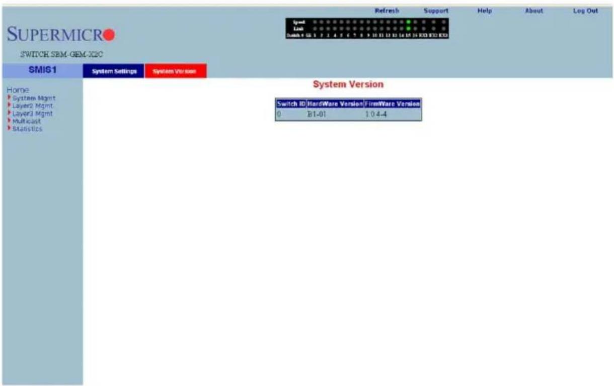
Clicking the SYSTEM VERSION tab brings up the SYSTEM VERSION page (Figure 7-8). This page displays the hardware and firmware version of the switch.
File Management
Figure 7-9. File Management Page
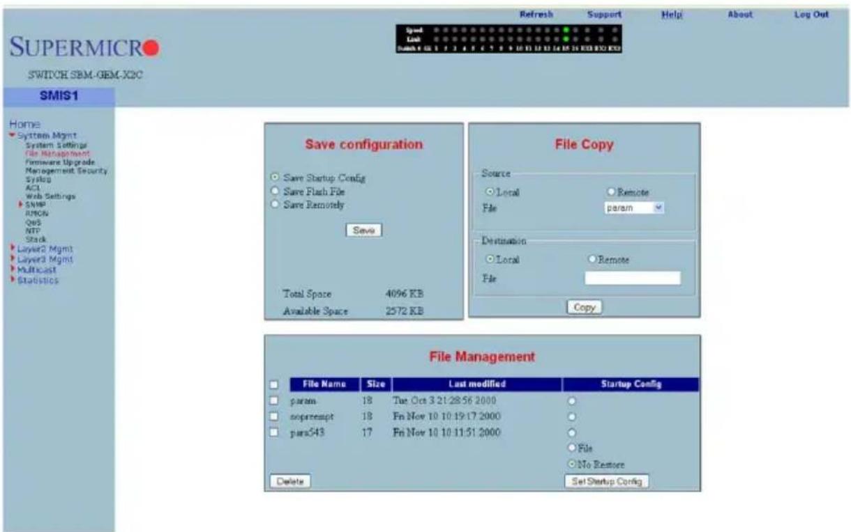
Clicking the FILE MANAGEMENT link brings up the FILE MANAGEMENT page (Figure 7-9). The FILE MANAGEMENT page helps you to manage the configuration files in the switch. This page provides three main features.
- Save Configuration
- File Copy
- File Management
Save Configuration
You can save a currently running switch configuration in the following three ways:
- Save Startup Config - This option saves the currently running configuration in a local flash file with the file name configured as a "startup configuration" file.
- Save Flash File - This option saves the currently running configuration in local flash file with a user specified file name.
- Save Remotely - This option saves the currently running configuration into a remote TFTP server. You need to provide the IP address and file name of the TFTP server for this option.
The total configuration memory space and available free space are also displayed for your reference.
File Copy
You can copy a local file to or from a remote TFTP server. This feature is useful to create a backup of configuration files remotely, and also to download configuration files from remote computers to the switch. You need to provide a local file name and also the remote TFTP server's IP address and file name for this feature.
File Management
This section displays information about the configuration files stored in the switch and allows you to do any of the following actions:
- You can select one or more files and delete them.
- You can choose a Startup Configuration file from this file list.
- You can choose the F ILE option and enter a name for a Startup Configuration file.
- You can also choose the N O RESTORE option for not loading any configuration files on the next reboot of the switch.
Firmware Upgrade
Figure 7-10. Firmware Upgrade Page
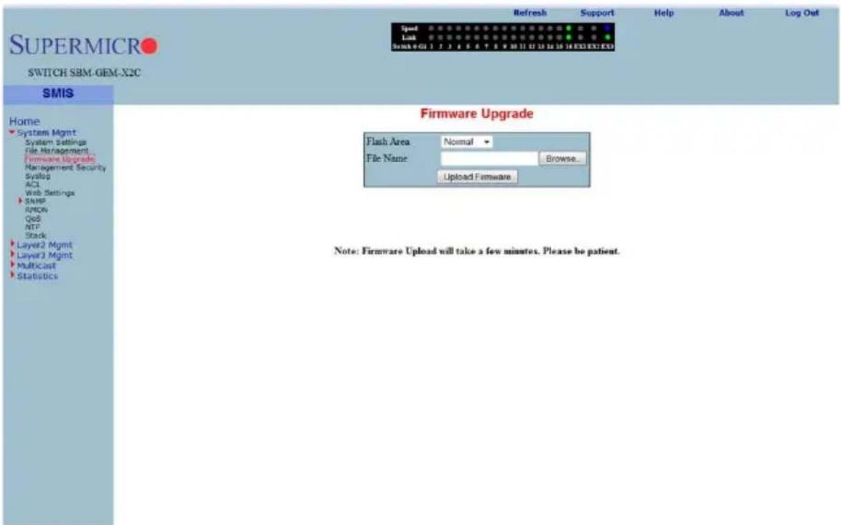
Clicking the FIRMWARE UPGRADE link brings up the FIRMWARE UPGRADE page (Figure 7-10). This page allows you to upgrade the firmware in normal or fallback memory. In stacking, the firmware is upgraded in all stack members automatically.
Management Security
The MANAGEMENT SECURITY link provides configuration for the following features:
- "Management Security Basic Settings" on page 7-15
- "Management User Account" on page 7-16
- "Radius" on page 7-17
• "TACACS+ Global Settings" on page 7-18
• "TACACS+ Server Configuration" on page 7-19 - "IP Authorized Manager" on page 7-20
• "SSH Configuration" on page 7-21 - "SSLConfiguration" on page 7-22
Management Security Basic Settings
Figure 7-11. Management Security Basic Settings Page
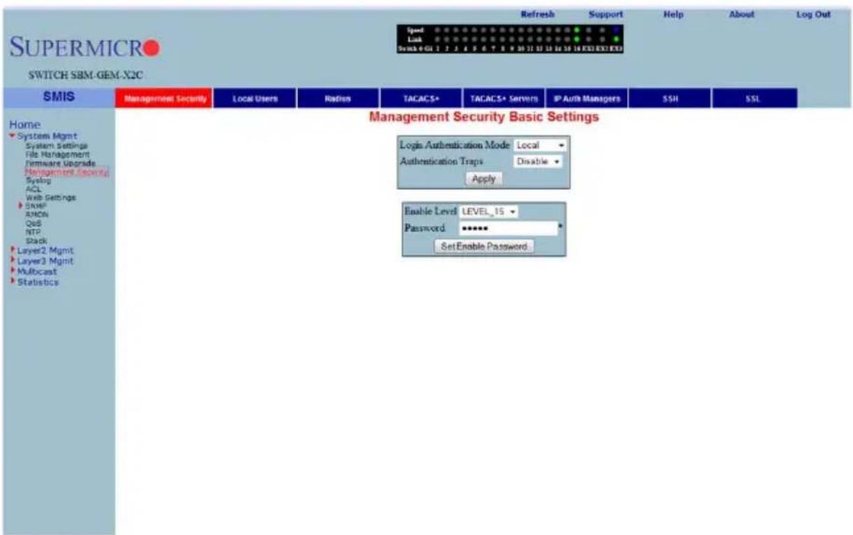
Clicking the MANAGEMENT SECURITY tab brings up the MANAGEMENT SECURITY BASIC SETTINGS page (Figure 7-11). This page allows you to setup the below listed basic security parameters (Table 7-3).
Table 7-3. Management Security Basic Settings Page Parameters
| Parameter Description | |
| Authentication mode | Use this parameter to choose the mode of authentication for management access. By default the management access is authenticated with LOCAL user accounts information. However you can choose to authenticate using Radius or TACACS instead. |
| Authentication traps | You can enable SNMP Traps for SNMP access authentication events using this parameter.. |
Administrative users can also create Enable Passwords in this page. Low privilege users can use these Enable Passwords in the WEB SETTINGS page to enable access to privilege configurations.
Administrative users can set an Enable Password for all privilege levels. By default, the Enable Password is set only for the highest level (Level_15). This default password is the same as the default password set for the ADMIN user login.
Management User Account
Figure 7-12. Management User Account Page
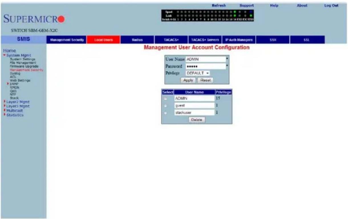
Clicking the LOCAL USERS tab brings up the MANAGEMENT USER ACCOUNT CONFIGURATION page (Figure 7-12). This page allows you to create or delete local user accounts. You need more than privilege Level_5 to view all pages and need more than privilege Level_10 for changing the configurations. The highest, Level_15, is for Administrator privilege.
Radius
Figure 7-13. Radius Server Configuration Page
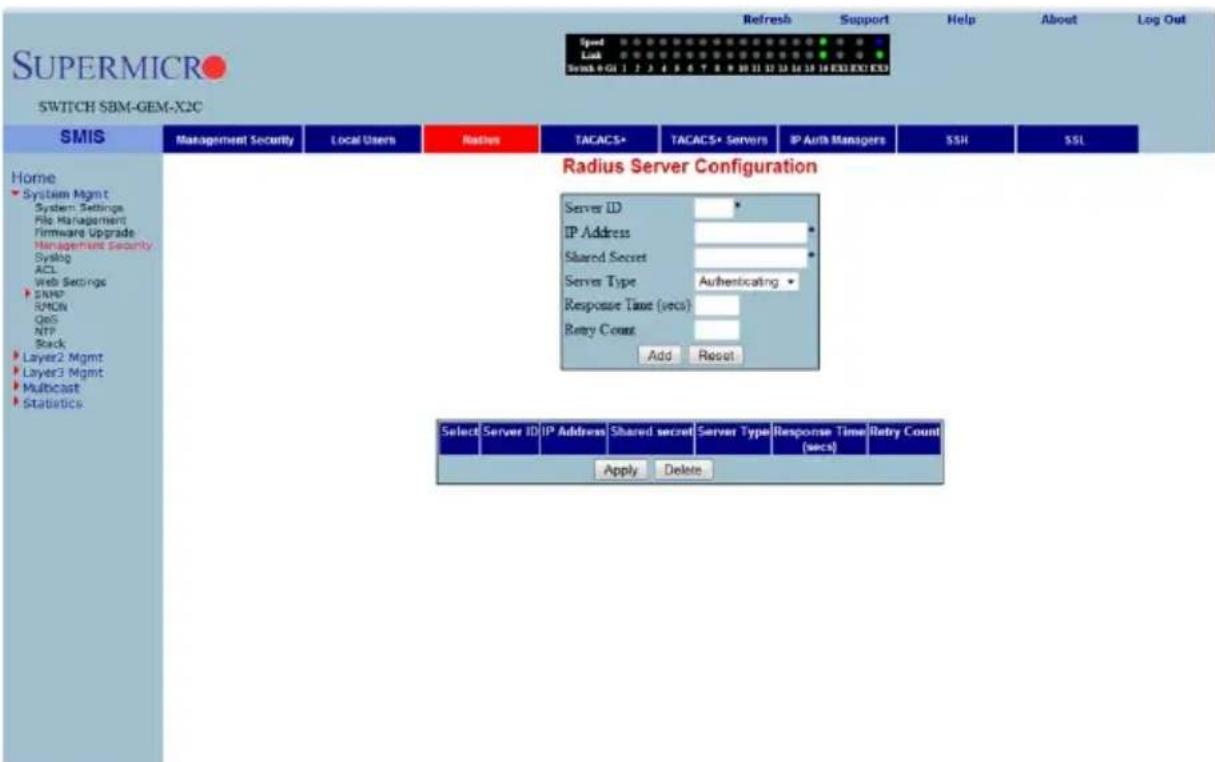
Clicking the RADIUS tab brings up the RADIUS SERVER CONFIGURATION page (Figure 7-13). This page allows you to configure the RADIUS server parameters as shown in Table 7-4.
Table 7-4. Radius Server Configuration Page Parameters
| Parameter Description | |
| Server ID This parameter specifies the unique identifier of the Radius Server Entry. | |
| IP Address | This parameter specifies the IP Address of the Radius Server. |
| Shared Secret | Use this parameter to specify the secret string, which is to be shared between the Radius Server and the Radius Client. |
| Server Type | This parameter specifies the following RADIUS server type• Authentication• Accounting• Both (Authentication and Accounting). |
| Response Time (secs) | This parameter specifies the maximum time that the Radius Server has to respond for a request from the Radius Client. |
| Retry Count | This parameter specifies the maximum number of times a radius request is re-transmitted before getting a response from the Radius Server. |
TACACS+ Global Settings
Figure 7-14. TACACS+ Global Settings Page
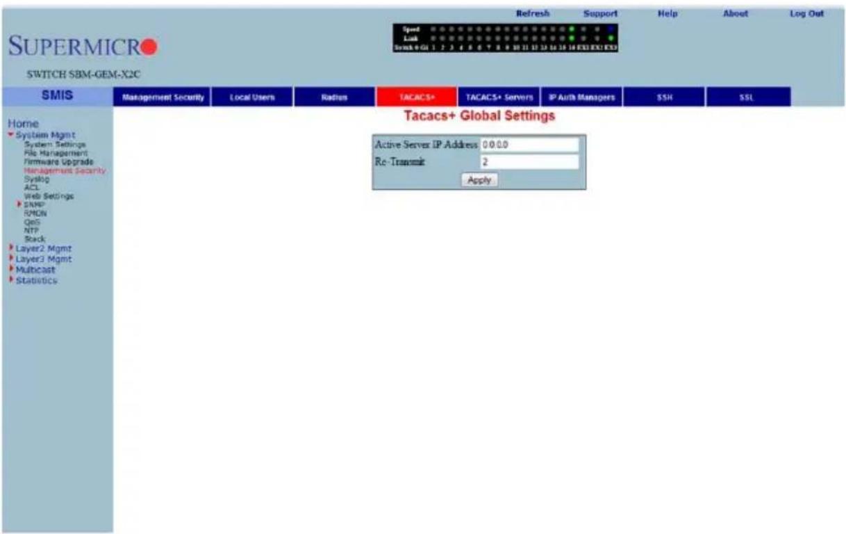
The TACACS+ GLOBAL SETTINGS page (Figure 7-14) allows you to configure TACACS retries and choose an active TACACS server. The parameters for this page are shown in Table 7-5.
Table 7-5. TACACS+ Global Settings Page Parameters
| Parameter Description | |
| Active Server IP Address | This parameter specifies the IP address of the active TACACS server. This server should have been already configured in the following TACACS+ SERVER CONFIGURATION page (Figure 7-15). |
| Retries | This parameter determines the number of times the switch searches the active TACACS server from the list of servers maintained. The allowed values are between 1 to 100. |
TACACS+ Server Configuration
Figure 7-15. TACACS+ Server Configuration Page
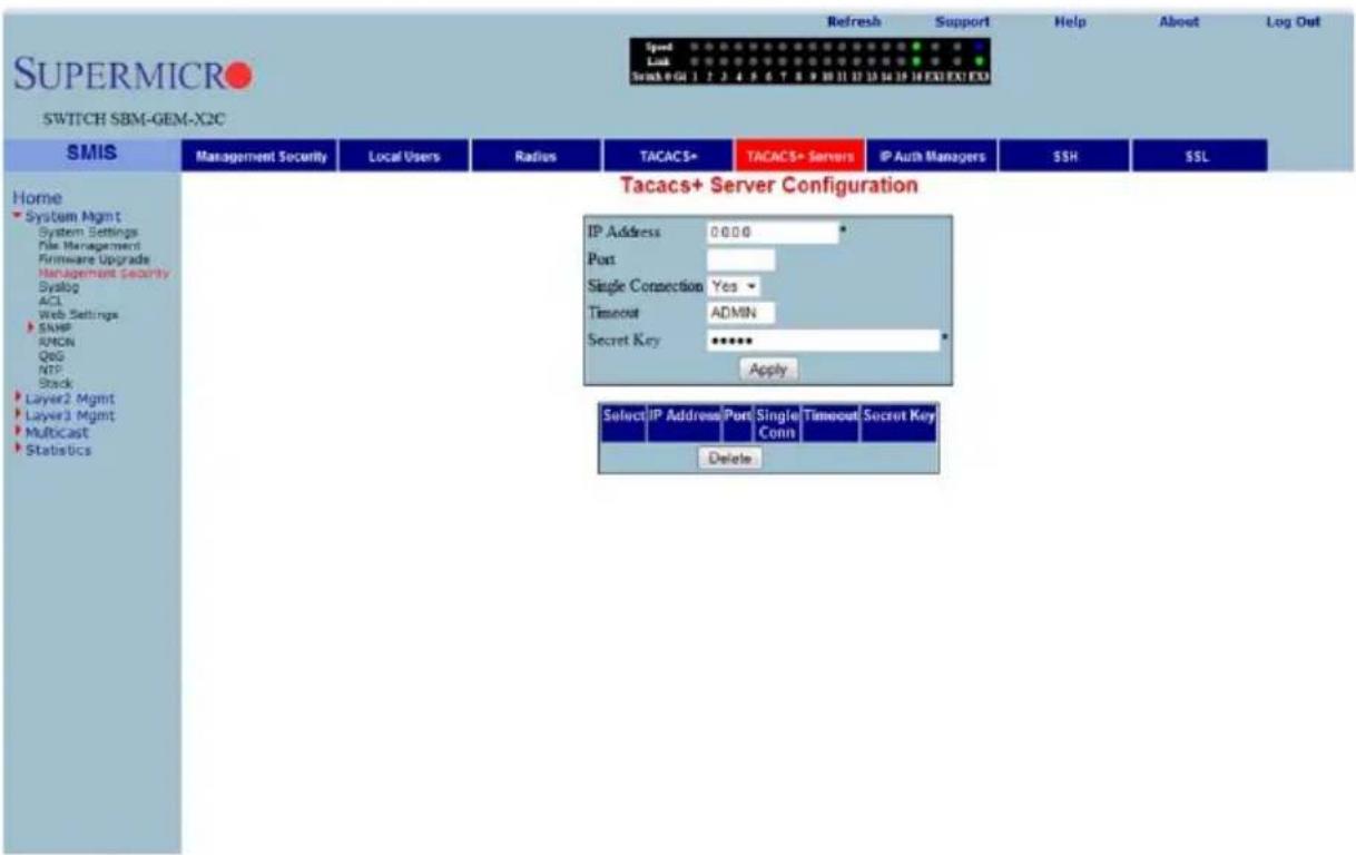
Clicking the TACACS+ SERVERS tab brings up the TACACS+ SERVER CONFIGURATION page (Figure 7-15), which allows you to configure TACACS servers. The parameters for this page are shown in Table 7-6.
Table 7-6. TACACS+ Server Configuration Page Parameters
| Parameter Description | |
| IP Address This parameter specifies the IP address of the TACACS server. | |
| Port | Use this parameter to specify the TCP port for TACACS protocol. |
| Single Connection | Specify Yes or No for a single TCP connection. If Yes, it establishes only a single TCP connection with a given TACACS server. |
| Timeout | The time for which the switch will wait for a response from the TACACS server before closing the connection is specified with this parameter. It is configurable in seconds, with the default as 5-seconds. |
| Secret Key This parameter specifies the encryption key for the given TACACS server. | |
IP Authorized Manager
Figure 7-16. IP Authorized Manager Page
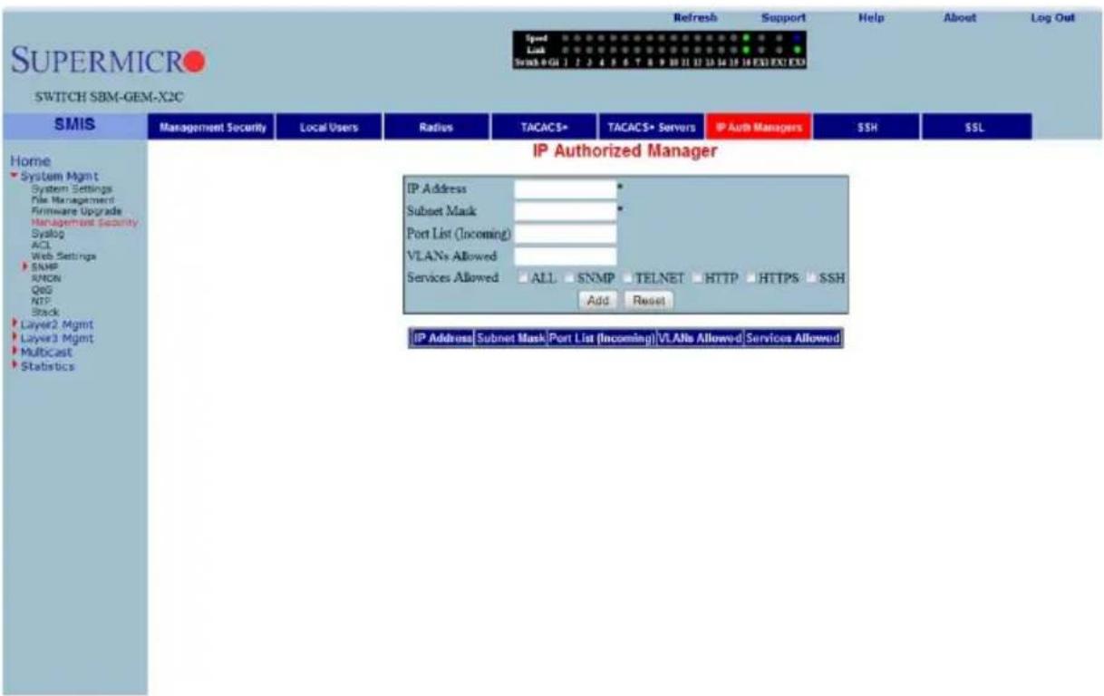
Clicking the IP AUTH MANAGER tab brings up the IP AUTHORIZED MANAGER page (Figure 7-16), which allows you to configure allowed management nodes for managing the switch. The parameters for this page are shown in Table 7-7.
Table 7-7. IP Authorized Manager Page Parameters
| Parameter Description | |
| IP Address | This parameter specifies the IP address of the manager. An address 0.0.0.0 indicates “Any Manager”. |
| Subnet Mask | This parameter specifies the sub-network mask for the specified IP address. |
| Port List (Incoming) | This lists the port through which the manager can access this switch. Ports can be comma separated or provided as a range (for example 1,2,3 or 1-3 or 1,2-3). |
| VLANs Allowed | This parameter specifies the VLANs through which the manager can access this switch. VLANs can be comma seperated or provided as range (for example 1,2,3 or 1-3 or 1,2-3). |
| Services Allowed | These control buttons are used to indicate the service type, and can be one or more of the following: TELNET, SSH, HTTP, HTTPS, SNMP or ALL. |
SSH Configuration
Figure 7-17. SSH Configuration
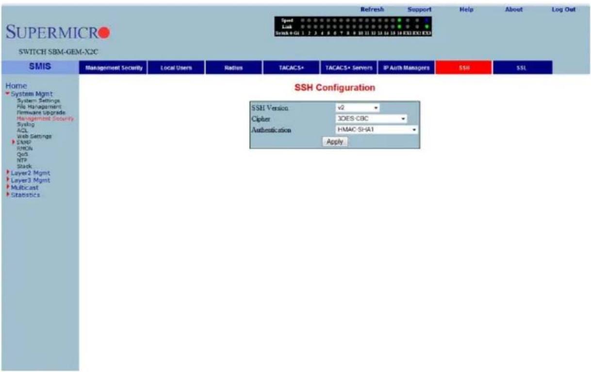
Clicking the SSH tab brings up the SSH CONFIGURATION page (Figure 7-17), which allows you to configure the SSH (Secure Shell) version and keys. The parameters for this page are shown in Table 7-8.
Table 7-8. SSH Configuration Page Parameters
| Parameter Description | |
| SSH Version | The default for this parameter is v2. You can choose to configure this as compatible with v1 instead. |
| Cipher | The default for this parameter is 3DES-CBC. You can instead choose to configure it as 3DES-CBC or DES-CBC or both |
| Authentication | This parameter's default is HMAC-SHA1. You can instead choose to configure it as HMAC-SHA1 or HMAC-MD5 or both. |
SSLConfiguration
Figure 7-18. SSL Configuraiton Page
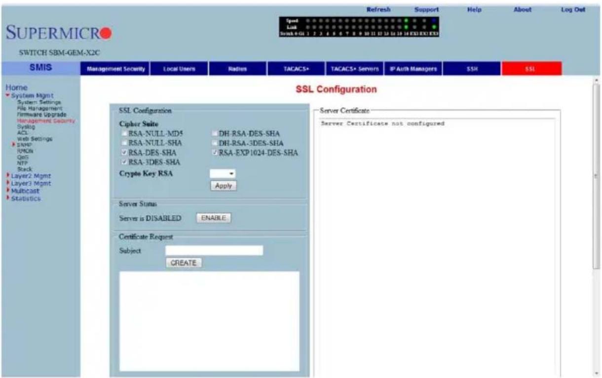
Clicking the SSL tab brings up the SSL CONFIGURATION page (Figure 7-18), which allows you to configure SSL (Secure Sockets Layer) parameters and generate SSL certificates for HTTPS. To configure SSL and enable HTTPS, follow the procedure below using this page.
Configuring SSL and Enabling HTTPS
- Configure C IPHER SUITE and CRYPTO KEY RSA with your chosen parameters.
- Create a certificate request by entering the subject name and clicking on the CREATE button.
- When the page reloads, the text box below the CREATE button will display a certificate request. Copy and paste these contents to a text file that says a.csr.
- To generate an SSL certificate, the openssl application can be used. The sub-steps below can be executed in any Linux machine to generate SSL certificates. For other openssl implementations, refer to the openssl documentation to find the equivalent steps for them.
a. Execute the below command in the Linux shell.
openssl req -x509 -newkey rsa:1024 -keyout cakey.pem -out cacert.pem
b. Execute the below command also in a Linux shell.
openssl x509 -req -in a.csr -out cert.pem -CA cacert.pem -CAkey cakey.pem -CAcreateserial
The above steps will generate the certificate file cert.pem.
- Open the generated certificate file cert.pem and delete the first line (---BEGIN CERTIFICATE ---) and last line (----END CERTIFICATE--).
- Join all the remaining lines as single lines to avoid line breaks being processed and copy/paste these joined texts in the ENTER CERTIFICATE text box back in the SSL CONFIGURATION page.
- Click the CONFIGURE button.
This configures the certificate and saves it to flash memory.
Syslog
The Syslog link provides configuration controls for the following features:
- "Syslog Configuration" on page 7-24
- "Syslog Mail Configuration" on page 7-25
Syslog Configuration
Figure 7-19. Syslog Configuration Page
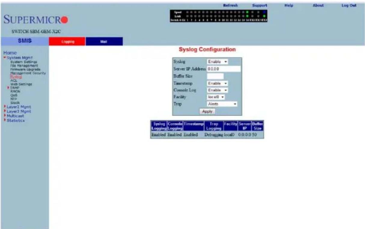
Clicking the LOGGING tab brings up the SYSLOG CONFIGURATION page (Figure 7-19), which allows you to configure logging parameters. The parameters for this page are shown in Table 7-9.
Table 7-9. Syslog Configuration Page Parameters
| Parameter Description | |
| Syslog This parameter enables or disables the Syslog feature. | |
| Server IP Address | This parameter specifies the Syslog server IP address. Make sure the Server IP is reachable. |
| Buffer Size | The buffer size is specified in log entries. Max entries buffered is 200. |
| Timestamp | This parameter allows you to enable or disable the adding of a timestamp to the log messages. |
| Console Log This parameter | allows you to enable or disable logging to the console. |
| Facility | This parameter allows you to select supported facilities. The switch supports syslog standard supported facilities LOCAL0, LOCAL1, LOCAL2, LOCAL3, LOCAL4, LOCAL5, LOCAL6, LOCAL7 and USER. |
| Traps | This parameter helps you to select a particular trap type. The following types of traps are supported ALERTS, CRITICAL, DEBUGGING, EMERGENCIES, ERROR, INFORMATIONAL, NOTIFICATION and WARNINGS. |
Syslog Mail Configuration
Figure 7-20. Syslog Mail Configuration Page
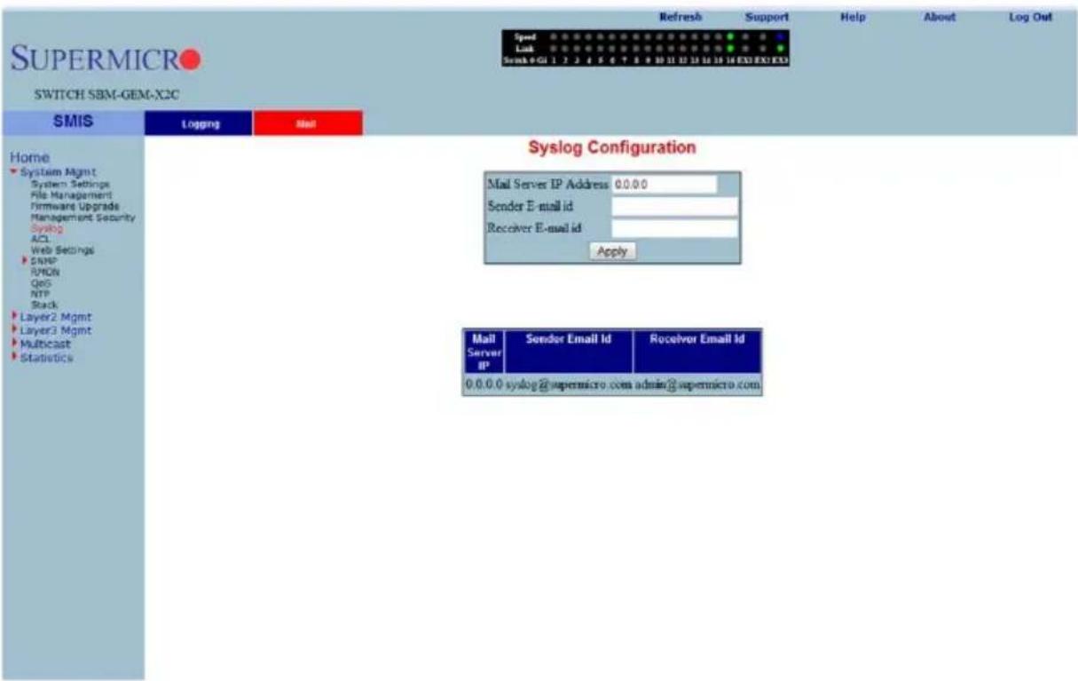
Clicking the MAIL tab brings up the SYSLOG MAIL CONFIGURATION page (Figure 7-20), which allows you to configure the mail server and mail addresses for the syslog feature. The parameters for this page are shown in Table 7-10.
Table 7-10. Syslog Mail Configuration Page Parameters
| Parameter Description | |
| Mail Server IP Address | This parameter specifies the IP address of the mail server. Make sure the mail server is reachable. |
| Sender Email ID | This parameter specifies the Email ID to be shown as the From address on Syslog Emails. |
| Receiver Email ID This parameter specifies the receipent Email address for Syslog Emails. | |
ACL
The ACL link allows you to configure the Access Control List for the switch. You can configure ACL on the following three pages:
• "MAC Based ACL" on page 7-26
• "IP Standard ACL" on page 7-27
• "IP Extended ACL" on page 7-28
MAC Based ACL
Figure 7-21. MAC ACL Configuration Page
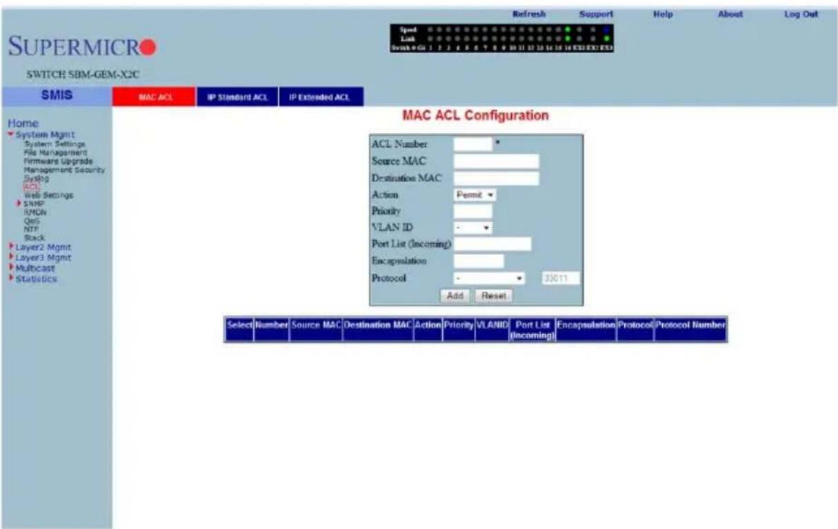
Clicking the MAC ACL tab brings up the MAC ACL CONFIGURATION page (Figure 7-21), which displays the various parameters to configure the MAC Access List. The parameters for this page are shown in Table 7-11.
Table 7-11. MAC ACL Configuration Page Parameters
| Parameter Description | |
| ACL Number This parameter | specifies a unique ID for the access list. |
| Source and Destination MAC | These fields specify both the Source MAC Address and Destination MAC Address, for which the access list must be applied. Both the Source and Destination MAC Addresses must be configured for the status of the access list to be active. |
| Action This parameter specifies the action to be taken for the access list. | |
| Priority | This parameter specifies the priority for the access list. |
| VLAN ID | This parameter specifies the VLAN ID for which the access list has to be applied. |
| Port List (Incoming) | This parameter specifies the Port List for which the access list has to be applied. |
| Encapsulation | This parameter specifies the Encapsulation type of the packet for which the access list has to be applied. |
| Protocol | This parameter specifies the non-IP protocol type of the packet for which the access list has to be applied. |
IP Standard ACL
Figure 7-22. IP Standard ACL Configuration Page
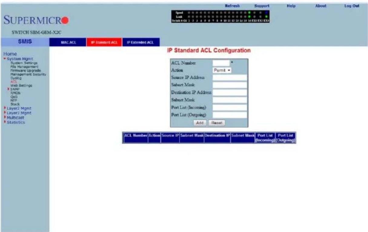
Clicking the IP STANDARD ACL tab brings up the IP STANDARD ACL CONFIGURATION page (Figure 7-22), which displays the various ACL (Access Control List) parameters to configure the Standard IP access lists. The parameters for this page are shown in Table 7-12.
Table 7-12. IP Standard ACL Configuration Page Parameters
| Parameter Description | |
| ACL Number | This parameter specifies the unique ID for the access list. This value must be in the range from 1 to 1000. |
| Action | This parameter specifies whether the packets must be allowed or dropped when a match has been found. |
| Source and Destination IP Address | This parameter specifies the IP Address of the Source and Destination for which the access list must be applied. |
| Subnet Mask | This parameter specifies the Source and Destination Address Mask corresponding to the IP Address. |
| Ports List (Incoming) | This parameter specifies the Incoming Port List for which the access list has to be applied. |
| Ports List (Outgoing) | This parameter specifies the Outgoing Port List for which the access list has to be applied. |
IP Extended ACL
Figure 7-23. IP Extended ACL Page
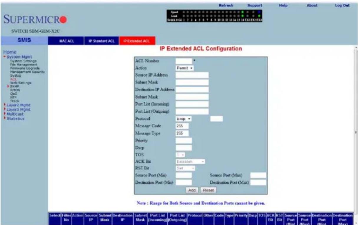
Clicking the IP EXTENDED ACL tab brings up the IP EXTENDED ACL CONFIGURATION page (Figure 7-23), which displays the various parameters required to configure the Extended IP access lists. The parameters for this page are shown in Table 7-13.
Table 7-13. IP Extended ACL Configuration Page Parameters
| Parameter Description | |
| ACL Number | This parameter specifies the unique ID for the access list. This value must be in the range from 1001 to 65535. |
| Action | This parameter specifies whether the packets must be allowed or dropped when a match has been found. |
| Source and Destination IP Address | This parameter specifies the IP Address for which the access list must be applied. |
| Subnet Mask | This parameter specifies the Address Mask corresponding to the IP Address. |
| Ports List (Incoming) | This parameter specifies the Incoming Port List for which the filter has to be applied. |
| Ports List (Outgoing) | This parameter specifies the Outgoing Port List for which the filter has to be applied. |
| Protocol This parameter specifies the type of protocol. | |
| Message Code | This parameter specifies the Message Code to be checked for ICMP Packets. |
| Message Type | This parameter specifies the Message Type to be checked for ICMP Packets. |
| Priority This parameter specifies the Priority for the filter. | |
| TOS This parameter specifies the Type of Service for the access list. | |
| ACK Bit | This parameter indicates the TCP Ack Bit to be checked against the incoming packet. |
| RST Bit | This parameter indicates the TCP Reset Bit to be checked against the incoming packet. |
| Source Port (Min) | These parameters specify the range of TCP/UDP sourceports from which the access list must be applied. |
| Source Port (Max) | |
| Destination Port (Min) | These parameters specify the destination ports to which the access list must be applied |
| Destination Port (Max) | |
WEBGUI Settings
Figure 7-24. Web GUI Settings Page
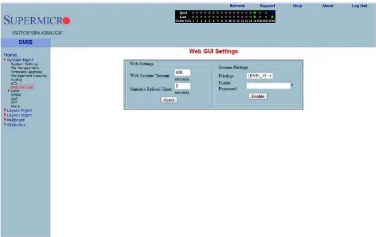
Clicking the WEB SETTINGS link brings up the WEB GUI SETTINGS page (Figure 7-24), which displays all basic Web GUI settings. The parameters for this page are shown in Table 7-14.
Table 7-14. Web GUI Settings Page Parameters
| Parameter Description | |
| Session timeout | This timeout value is used to automatically logout inactive user sessions. The default value is 5-minutes (600-seconds). |
| Statistics Refresh Timer | The statistics pages (grouped under "Statistics" node in left side tree) can be set to auto refresh based on this Statistics Refresh Timer. The default value zero means no auto refresh by default. |
| Session Privilege | This displays the current privilege level of the logged in user. You can choose to enter another privilege level using this configuration if you have the Enable Password for the required privilege levels. The Enable Passwords for different levels are configurable in the Management Security web page. |
SNMP
Figure 7-25. SNMP Agent Control Settings Page
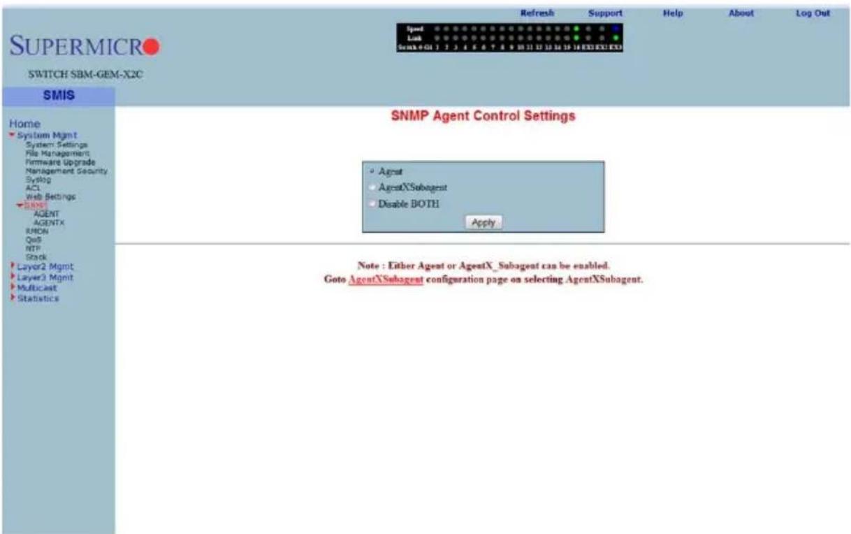
Clicking the SNMP link brings up the SNMP AGENT CONTROL SETTINGS page (Figure 7-25). SMIS supports the SNMP Agent or SNMP AgentX Sub-agent. The SNMP Agent or AgentX Sub-agent can be enabled or both can be disabled.
The SNMP Agent provides the following sub-page configurations shown in the table below.
Table 7-15. SNMP Agent Configuration Pages
| Configuration Page Description | |
| "SNMP Community Settings" on page 7-32 | This page allows you to configure the SNMP community including the COMMUNITY INDEX, NAME, SECURITY NAME, CONTEXT NAME, TRANSPORT TAG and STORAGE TYPE. |
| "SNMP Group Settings" on page 7-33 | This page allows you to configure SNMP groups including GROUP NAME, SECURITY NAME, SECURITY MODEL and STORAGE TYPE. |
| "SNMP Group Access Settings" on page 7-34 | This page allows you to configure access parameters for SNMP groups including GROUP NAME, SECURITY MODEL, SECURITY LEVEL, STORAGE TYPE, and READ, WRITE and NOTIFY VIEW. |
| "SNMP View Tree Settings" on page 7-35 | This page allows you to configure an SNMP view tree including VIEW NAME, SUB TREE, MASK, TYPE OF THE VIEW and STORAGE TYPE. |
| "SNMP Target Address Settings" on page 7-36 | This page allows you to configure SNMP target including TARGET NAME, TARGET IP, TRANSPORT TAG, PARAM and STORAGE TYPE. |
| Configuration Page Description"SNMP Target Parameter Settings" on page 7-37 | This setting allows you to configure SNMP target parameters including PARAMETER NAME, MP MODEL, SECURITY MODEL, NAME, LEVEL and STORAGE TYPE. |
| "SNMP User Settings" on page 7-38 | This setting allows you to configure SNMP security including user name, AUTHENTICATION PROTOCOL, AUTHENTICATION KEY, PRIVACY PROTOCOL, PRIVACY KEY and STORAGE TYPE. |
| "SNMP Trap Settings" on page 7-39 | This setting allows you to configure SNMP trap notifications including NOTIFY NAME, NOTIFY TAG, NOTIFY TYPE and STORAGE TYPE. |
SNMP Community Settings
Figure 7-26. SNMP Community Settings Page
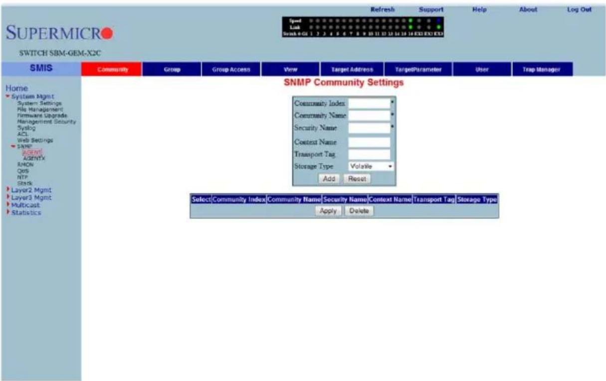
Clicking the COMMUNITY tab brings up the SNMP COMMUNITY SETTINGS page (Figure 7-26), which allows you to add SNMP managers or remove existing managers.. The parameters for this page are shown in Table 7-16.
Table 7-16. SNMP Community Settings Page Parameters
| Parameter Description | |
| Community index | This parameter sets the COMMUNITY INDEX identifier. |
| Community name | This parameter sets the COMMUNITY NAME string. |
| Security Name This parameter | set the User Name String. |
| Parameter DescriptionContext Name | This parameter sets the CONTEXT NAME that the management information is accessed from when using the community string, which is specified by the corresponding instance of the SNMP community name. |
| Transport Tag This parameter sets the T RANSPORT TAG Identifier. | |
| Storage Type | This parameter sets the Volatile Storage or Non-Volatile Storage setting. |
SNMP Group Settings
Figure 7-27. SNMP Group Settings Page
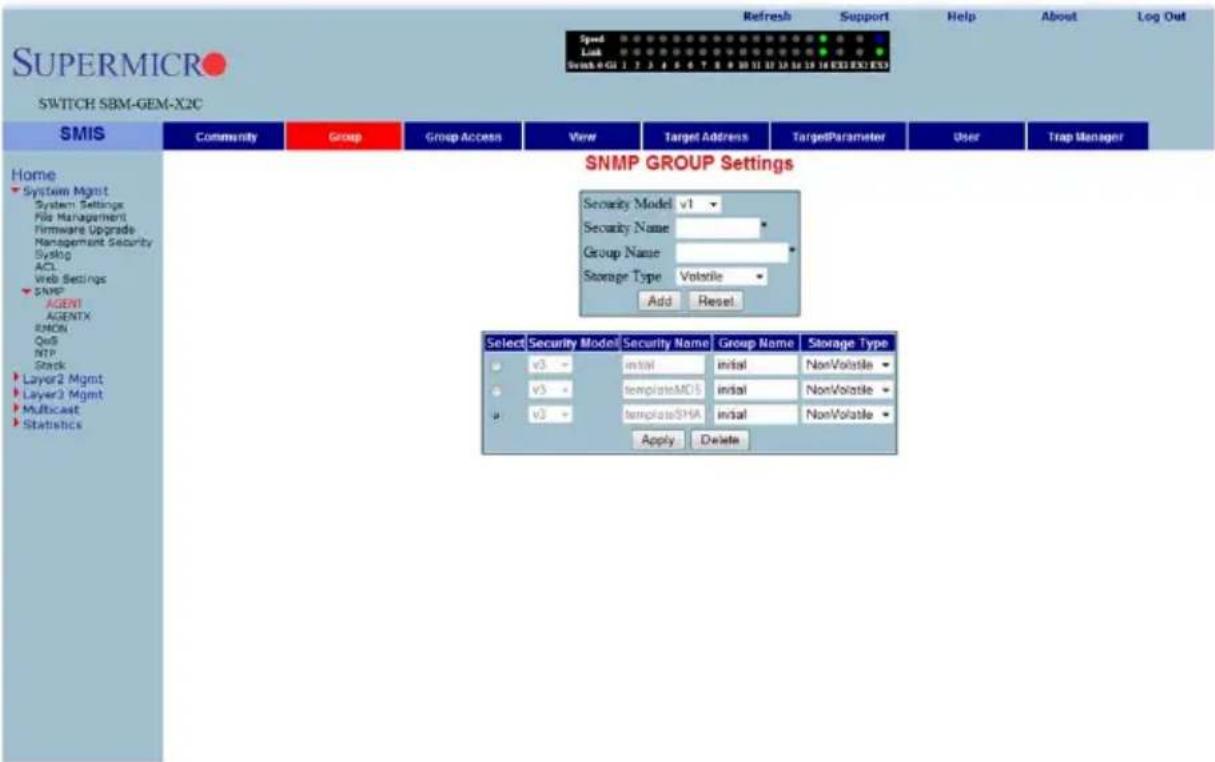
Clicking the GROUP tab brings up the SNMP GROUP SETTINGS page (Figure 7-27). This page helps you map a combination of the SECURITY MODEL and the SECURITY NAME into a GROUP NAME, which is used to define an access control policy. In addition, this page displays the STORAGE TYPE of the Group Table. The parameters for this page are shown in Table 7-17.
Table 7-17. SNMP Group Settings Page Parameters
| Parameter Description | |
| Security Model | This parameter allows you to select from version 1, version 2 or version 3 for the SECURITY MODEL used. |
| Security Name | Use this parameter to specify the SECURITY NAME string. |
| Group Name | Use this parameter to specify the GROUP NAME string. |
| Storage Type | Use this parameter to specify whether the STORAGE TYPE is Volatile or Non-Volatile. |
SNMP Group Access Settings
Figure 7-28. SNMP Group Access Settings Page
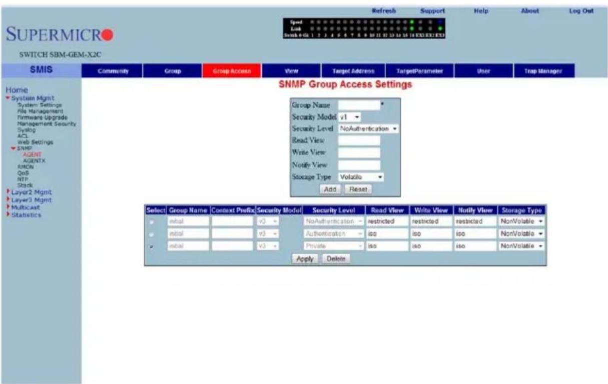
Clicking the GROUP ACCESS tab brings up the SNMP GROUP ACCESS SETTINGS page (Figure 7-28), which displays the access rights of groups. Each entry is indexed by a GROUP NAME, a Context Prefix, a SECURITY MODEL and a SECURITY LEVEL. A proper view name (READ, WRITE and MODIFY) must be used for access control checking. It also displays the STORAGE TYPE of the Group Access table. An SNMP Group must be created prior to the Group Access configuration.
The parameters for this page are shown in Table 7-18.
Table 7-18. SNMP Group Access Settings Page Parameters
| Parameter Description | |
| Group Name | This parameter allows you to specify the GROUP NAME string. |
| Security Model | This parameter allows you to specify whether SNMP version v1, v2 or v3 is used. Version 3 is the most secure model as it allows packet encryption with the private key word. |
| Security Level | With this parameter the no-authentication option disables authentication. The AUTHENTICATION option enables Message digest (MD5) or Secure Hash Algorithm (SHA) packet authentication. The PRIVATE option selects both AUTHENTICATION and PRIVACY. |
| Read View | This parameter allows you to specify the READ VIEW identifier. |
| Write View This parameter allows you to specify the W RITE VIEW identifier. | |
| Notify View | This parameter allows you to specify the NOTIFY VIEW identifier. |
| Storage Type | Use this parameter to specify whether the STORAGE TYPE is Volatile or Non-Volatile. |
SNMP View Tree Settings
Figure 7-29. SNMP View Tree Settings Page
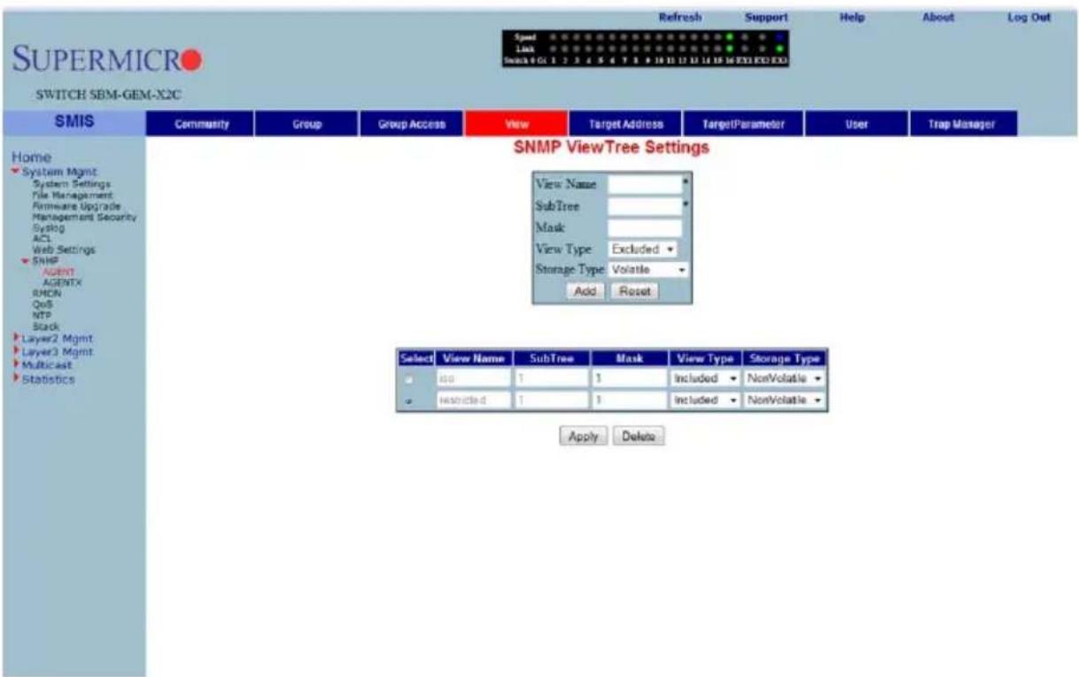
Clicking the VIEW tab brings up the SNMP VIEW TREE SETTINGS page (Figure 7-29), which allows configuration of view trees. A SUBTREE when combined with the corresponding instance of a MASK defines a family of view subtrees. The VIEW NAME is the name for a family of view subtrees. This page also displays the STORAGE TYPE of the VIEWTREE table. SNMP Group and SNMP Access settings have to be created prior to the Group View configuration.
The parameters for this page are shown in Table 7-19.
Table 7-19. SNMP View Tree Settings Page Parameters
| Parameter Description | |
| View Name | This parameter specifies a VIEW NAME string. |
| SubTree This parameter specifies a tree OID. | |
| Mask This parameter specifies an OID mask. | |
| View Type | This parameter specifies whether a VIEW TYPE is Included or Excluded. |
| Storage Type | Use this parameter to specify whether the STORAGE TYPE is volatile or non-volatile. |
SNMP Target Address Settings
Figure 7-30. SNMP Target Address Settings Page
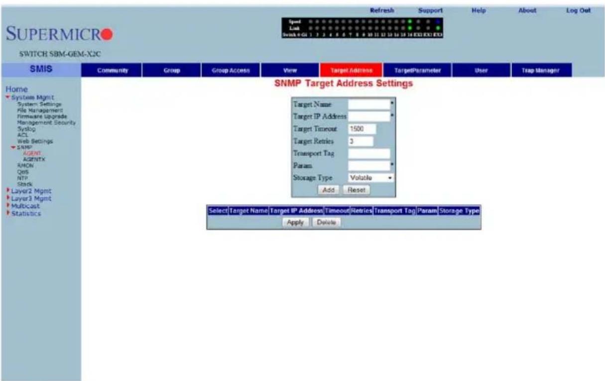
Clicking the TARGET ADDRESS tab brings up the SNMP TARGET ADDRESS SETTINGS page (Figure 7-30), which configures SNMP target address parameters. The parameters for this page are shown in Table 7-20.
Table 7-20. SNMP Target Address Settings Page Parameters
| Parameter Description | |
| Target Name | This parameter specifies a TARGET NAME as a unique identifier. |
| Target IP Address | The TARGET IP ADDRESS specifies a target address to be used in the generation of SNMP operations. |
| Target Timeout | TARGET TIMEOUT specifies the maximum round trip for communicating with the TARGET IP ADDRESS. |
| Target Retries | TARGET RETRIES specifies the number of attempts to be made when no response is received |
| Transport Tag | The TRANSPORT TAG value is used to select a target address for a particular operation. |
| Param | PARAM contains SNMP parameters to be used when generating messages to be sent to a transport address. |
| Storage Type | Use this parameter to specify whether the STORAGE TYPE is volatile or non-volatile. |
SNMP Target Parameter Settings
Figure 7-31. SNMP Target Parameter Settings Page
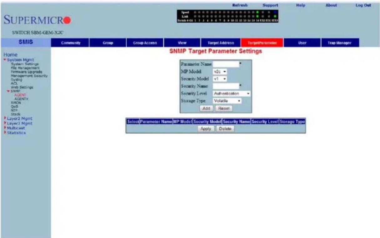
Clicking the TARGET PARAMETER tab brings up the SNMP TARGET PARAMETER SETTINGS page (Figure 7-31), which configures SNMP Target Address parameters. The parameters for this page are shown in Table 7-21.
Table 7-21. SNMP Target Parameter Settings Page Parameters
| Parameter Description | |
| Parameter Name | The target parameter is an unique name that specifies SNMP target information to be used in the generation of SNMP messages. |
| MP Model | The Message Processing (MP) Model is used when generating SNMP messages using this entry. |
| Security Model | The SECURITY MODEL is used when generating SNMP messages using this entry. |
| Security Name | The SECURITY NAME identifies the current PARAMETER NAME, on whose behalf SNMP messages will be generated. |
| Security Level | SECURITY LEVEL specifies the level of security used when generating SNMP messages. |
| Storage Type | STORAGE TYPE can be configured as Volatile or Non-Volatile. |
SNMP User Settings
Figure 7-32. SNMP Security Settings Page
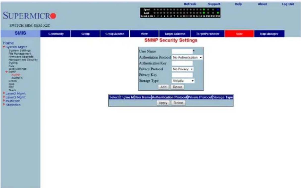
Clicking the USER tab brings up the SNMP SECURITY SETTINGS page (Figure 7-32), which configures users configured in the SNMP for the User-based Security Model. The parameters for this page are shown in Table 7-22.
Table 7-22. SNMP Security Settings Page Parameters
| Parameter Description | |
| User Name | USER NAME is the (User-based Security) model dependent security ID. |
| Authentication Protocol | The AUTHENTICATION PROTOCOL is used for authentication. |
| Authentication Key | The AUTHENTICATION KEY is the secret authentication key used for messages sent on behalf of this user to/from the SNMP. |
| Privacy Protocol | PRIVACY PROTOCOL is an indication of whether or not messages sent on behalf of this user to/from the SNMP are protected from disclosure, and if so, the type of privacy protocol that is used. |
| Privacy Key | PRIVACY KEY is an indication of whether or not messages sent on behalf of this user to/from the SNMP are protected from disclosure. |
| Storage Type | STORAGE TYPE can be configured as Volatile or Non-Volatile. |
SNMP Trap Settings
Figure 7-33. SNMP Trap Settings Page
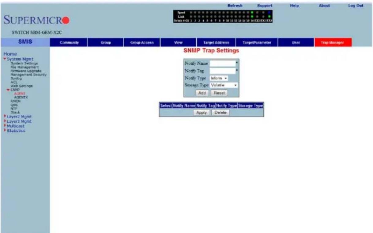
Clicking the TRAP MANAGER tab brings up the SNMP TRAP SETTINGS page (Figure 7-33), which configures the set of management targets that must receive notifications. The parameters for this page are shown in Table 7-23.
Table 7-23. SNMP Trap Settings Page Parameters
| Parameter Description | |
| Notify Name | NOTIFY NAME is a unique identifier associated with the entry. |
| Notify Tag | NOTIFY TAG contains a single tag value, which is used to select entries in the Target Address table. Any entry in the Target Address table that contains a tag value equal to the value of an instance of this Trap Manager, is selected. |
| Notify Type | The type of notification of the SNMP Trap Settings can be configured as Trap or Inform. |
| Storage Type | STORAGE TYPE can be configured as Volatile or Non-Volatile. |
SNMP AgentX
Figure 7-34. SNMP AgentX Subagent Settings Page
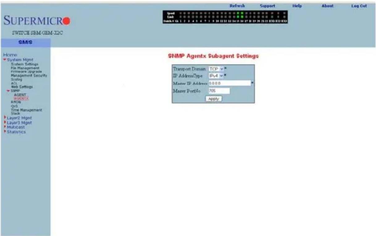
Clicking the AGENTX link brings up the SNMP AGENTX SUBAGENT SETTINGS page (Figure 7-34), which allows you to configure SNMP Agentx sub-agent parameters. The parameters for this page are shown in Table 7-24.
Table 7-24. SNMP AgentX Subagent Settings Page Parameters
| Parameter Description | |
| Transport Domain This parameter allows you to specify the TCP. | |
| IP Address Type | This parameter specifies IPv4 or IPv6 for the IP ADDRESS TYPE. |
| Master IP Address This parameter specifies the Master Agent IP address. | |
| Master Port No This parameter specifies the Master Port number. | |
RMON
The following pages can be used to set RMON (Remote Monitoring) features and settings:
- "RMON Basic Settings" on page 7-42
• "Event Configuration" on page 7-43 - "RMON Alarm Configuration" on page 7-44
- "Ethernet Statistics Configuration" on page 7-45
• "History Control Configuration" on page 7-46
RMON Basic Settings
Figure 7-35. RMON Basic Settings Page
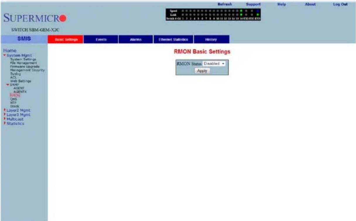
Clicking the BASIC SETTINGS tab brings up the RMON BASIC SETTINGS page (Figure 7-35), which enables/disables the RMON feature using the RMON Status parameter.
Event Configuration
Figure 7-36. Event Configuration Settings Page
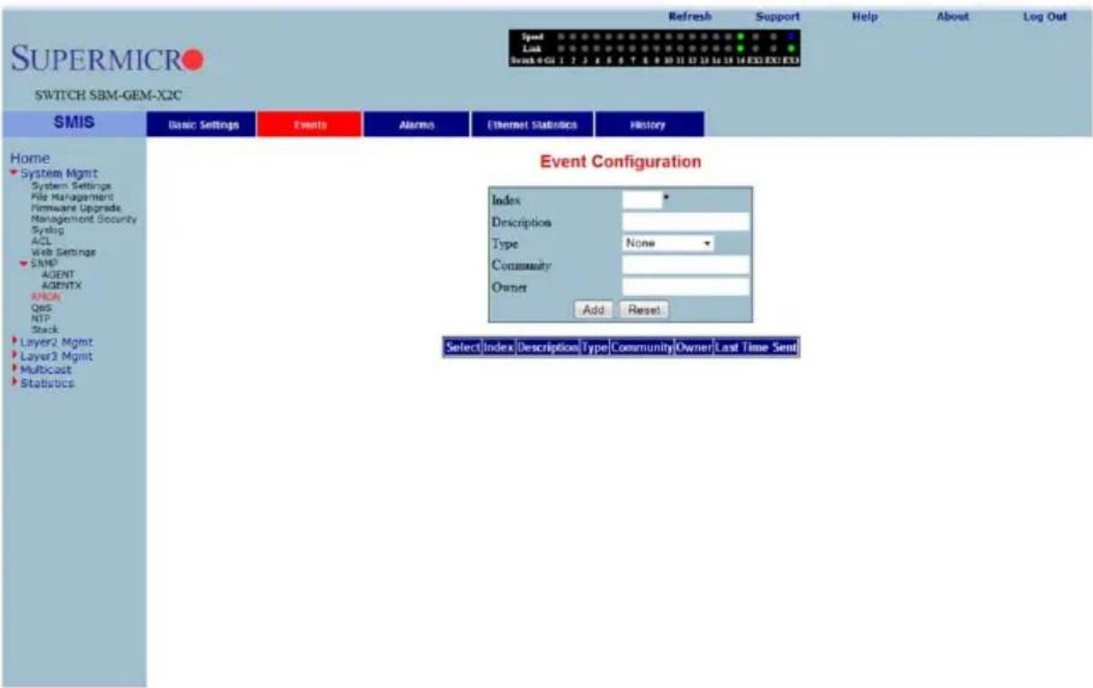
Clicking the EVENTS tab brings up the EVENT CONFIGURATIONS page (Figure 7-36), which configures RMON events. The parameters for this page are shown in Table 7-25.
Table 7-25. Event Configuration Page Parameters
| Parameter Description | |
| Index This parameter specifies the index to the Events table. | |
| Description This parameter specifies a brief description of the event. | |
| Type | This parameter specifies the event configured. This can be a Log, an SNMP Trap, Both, or None. For the event type to display, TRAP and Log and TRAP Community must be configured. |
| Community | This parameter specifies the SNMP community string used for this trap. This is relevant when an SNMP trap is requested for an event. For event type to display, TRAP and Log and TRAP Community must be configured. Also make sure the configured community is active before adding an event on that community. |
| Owner This parameter indicates the owner of this event. | |
| Last Time Sent This parameter denotes the time this event entry last generated an event. | |
RMON Alarm Configuration
Figure 7-37. RMON Alarm Configuration Page
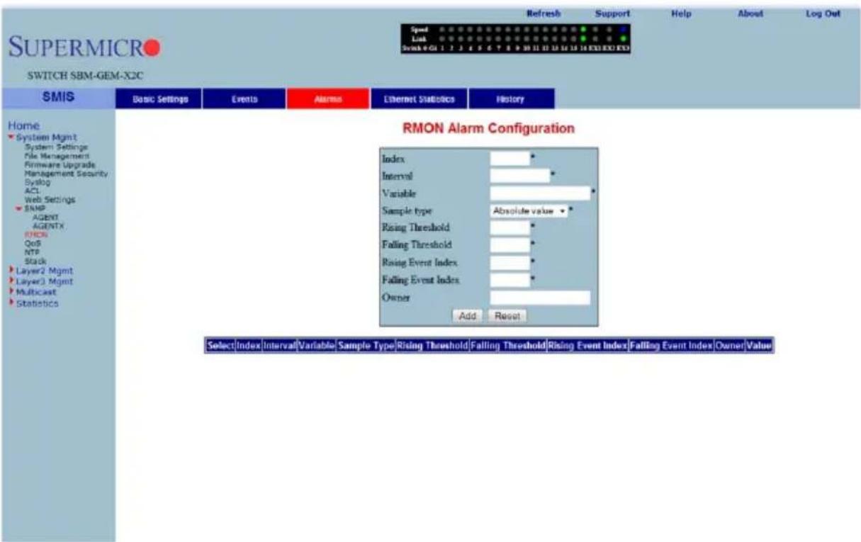
Clicking the ALARM tab brings up the RMON ALARM CONFIGURATION page (Figure 7-37), which configures RMON Alarm parameters. The parameters for this page are shown in Table 7-26.
Table 7-26. RMON Alarm Configuration Page Parameters
| Parameter Description | |
| Index This parameter specifies the table index. | |
| Interval | This parameter specifies the time interval for which the alarm monitors the variable. |
| Variable This parameter specifies the MIB object on which the alarm is set. | |
| Sample Type | You can set this parameter to an Absolute Value or as just an Incremental Value of the timer. |
| Rising Threshold | If the startup alarm is set as Rising Alarm and this threshold is reached, an alarm is raised. |
| Falling Threshold | If the startup alarm is set as Falling Alarm and this threshold is reached, an alarm is raised. |
| Rising Event Index | Indicates the index of the event to be raised when the RISING THRESHOLD is reached. |
| Parameter DescriptionFalling Event Index | Indicates the index of the event to be raised when the FALLING THRESHOLD is reached. |
| Owner Specifies the owner of the alarm. | |
Ethernet Statistics Configuration
Figure 7-38. Ethernet Statistics Configuration Page
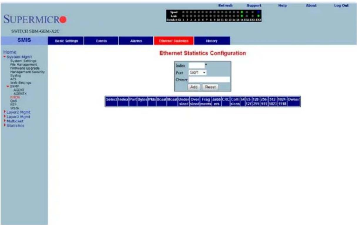
Clicking the ETHERNET STATISTICS tab brings up the ETHERNET STATISTICS CONFIGURATION page (Figure 7-38), which configures RMON Ethernet statistics parameters. The parameters for this page are shown in Table 7-27.
Table 7-27. Ethernet Statistics Configuration Page Parameters
| Parameter Description | |
| Index This parameter specifies the index to the table. | |
| Port This parameter specifies the Ethernet Port. | |
| Octets | This parameter specifies the total number of octets received from the network. |
| Packets | This parameter specifies the total number of packets received from the network. |
| Broadcast Packets | This parameter specifies the total number of broadcast packets received from the network. |
| Multicast Packets | This parameter specifies the total number of multicast packets received from the network. |
| Owner This parameter specifies the owner string. | |
History Control Configuration
Figure 7-39. History Control Configuration Page
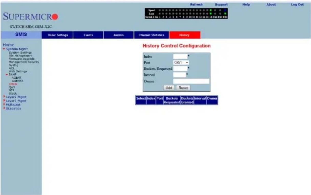
Clicking the HISTORY tab brings up the HISTORY CONTROL CONFIGURATION page (Figure 7-39), which configures RMON history parameters. The parameters for this page are shown in Table 7-28.
Table 7-28. History Control Configuration Page Parameters
| Parameter Description | |
| Index This parameter specifies the index to the table. | |
| Data Source | This parameter specifies the SNMP object ID of the variable for which the history is being collected. |
| Buckets Requested | Indicates the number of buckets to be configured for collecting the RMON statistics. |
| Interval | This parameter specifies the time interval between two successive polls to collect the statistics. |
| Owner Denotes the owner of | the RMON group of statistics. |
| Parameter DescriptionBuckets Granted Denotes the number of buckets granted for collecting the RMON statistics. | |
| Status | This parameter specifies the status of the History Control entry as either Valid or Invalid. |
QoS
The QoS link of the System page opens the QoS Basic Settings page. This page allows you to configure QoS through following pages:
• "QOS Basic Settings" on page 7-47
• "QOS Classmap Settings" on page 7-48
• "QOS Policymap Settings" on page 7-49
• "COSQ Scheduling Algorithm" on page 7-50
• "COSQ Weight and Bandwidth Configuration" on page 7-51
QOS Basic Settings
Figure 7-40. QOS Basic Settings Page
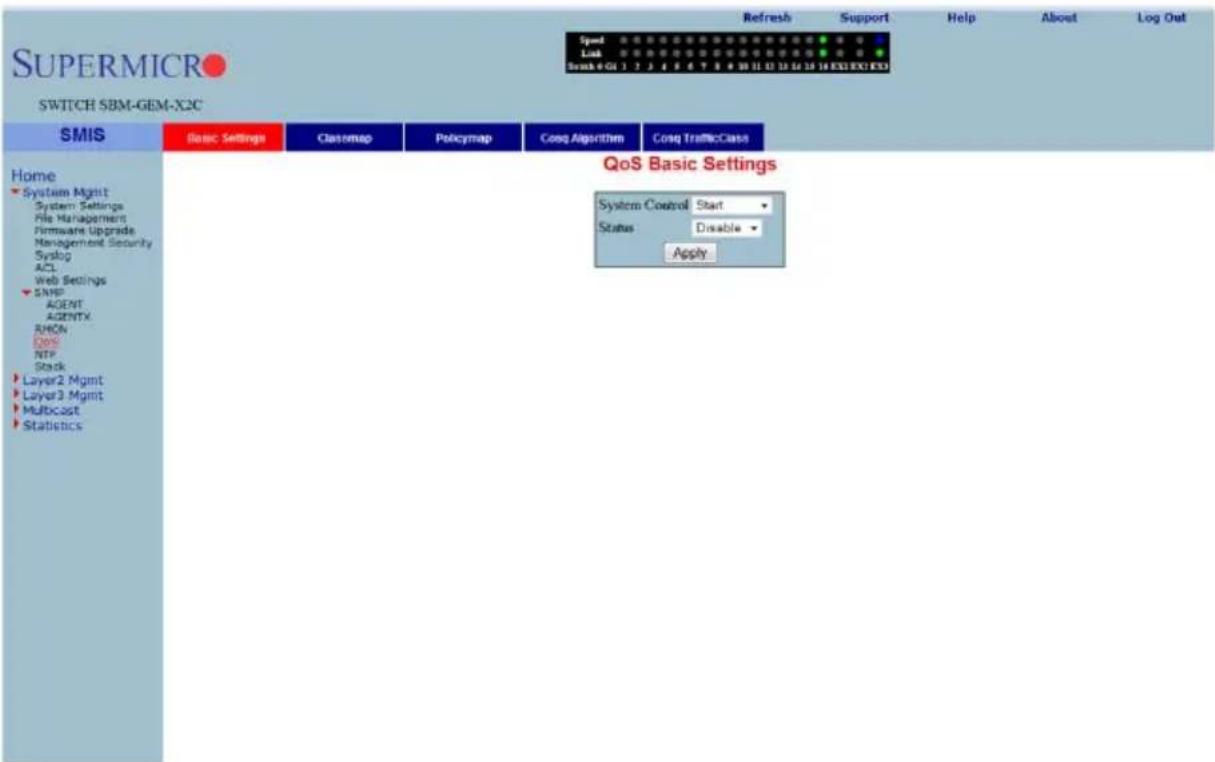
Clicking the BASIC SETTINGS tab brings up the QOS BASIC SETTINGS page (Figure 7-40), which allows you to configure QOS basic settings parameters. The parameters for this page are shown in Table 7-29.
Table 7-29. QOS Basic Settings Page Parameters
| Parameter Description | |
| System Control | With this parameter SYSTEM CONTROL can Start or Shutdown QoS. |
| Status This parameter allows enabling/disabling of the QoS status. | |
QOS Classmap Settings
Figure 7-41. QOS Classmap Settings Page
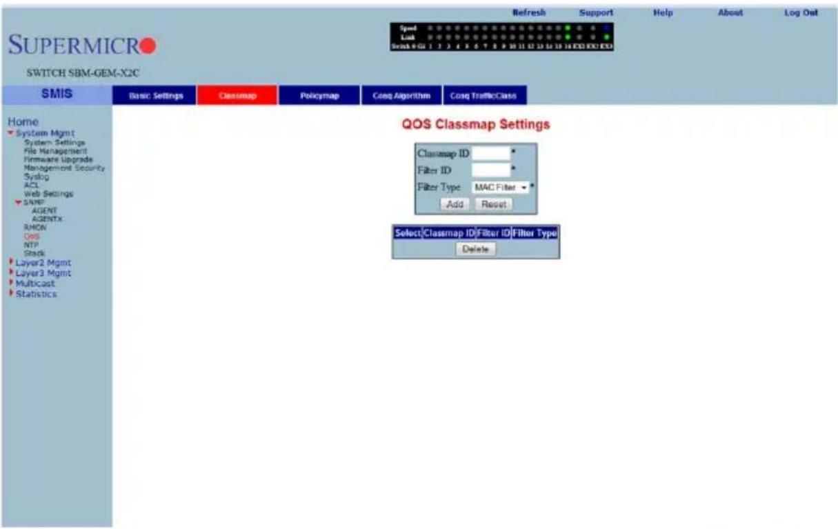
Clicking the CLASSMAP tab brings up the QOS CLASSMAP SETTINGS page (Figure 7-41), which is used to classify the stream of traffic. The parameters for this page are shown in Table 7-30.
Table 7-30. QOS Classmap Settings Page Parameters
| Parameter Description | |
| Classmap ID | This parameter specifies a unique ID for the Classmap. It must be in the range from 1 to 65535. |
| Filter ID | This parameter specifies the unique filter ID associated with this Classmap. |
| Filter Type | This parameter specifies the filter type associated with the Classmap. It can be set as either MAC filter (1) or IP filter (2). |
QOS Policymap Settings
Figure 7-42. QOS Policymap Settings Page
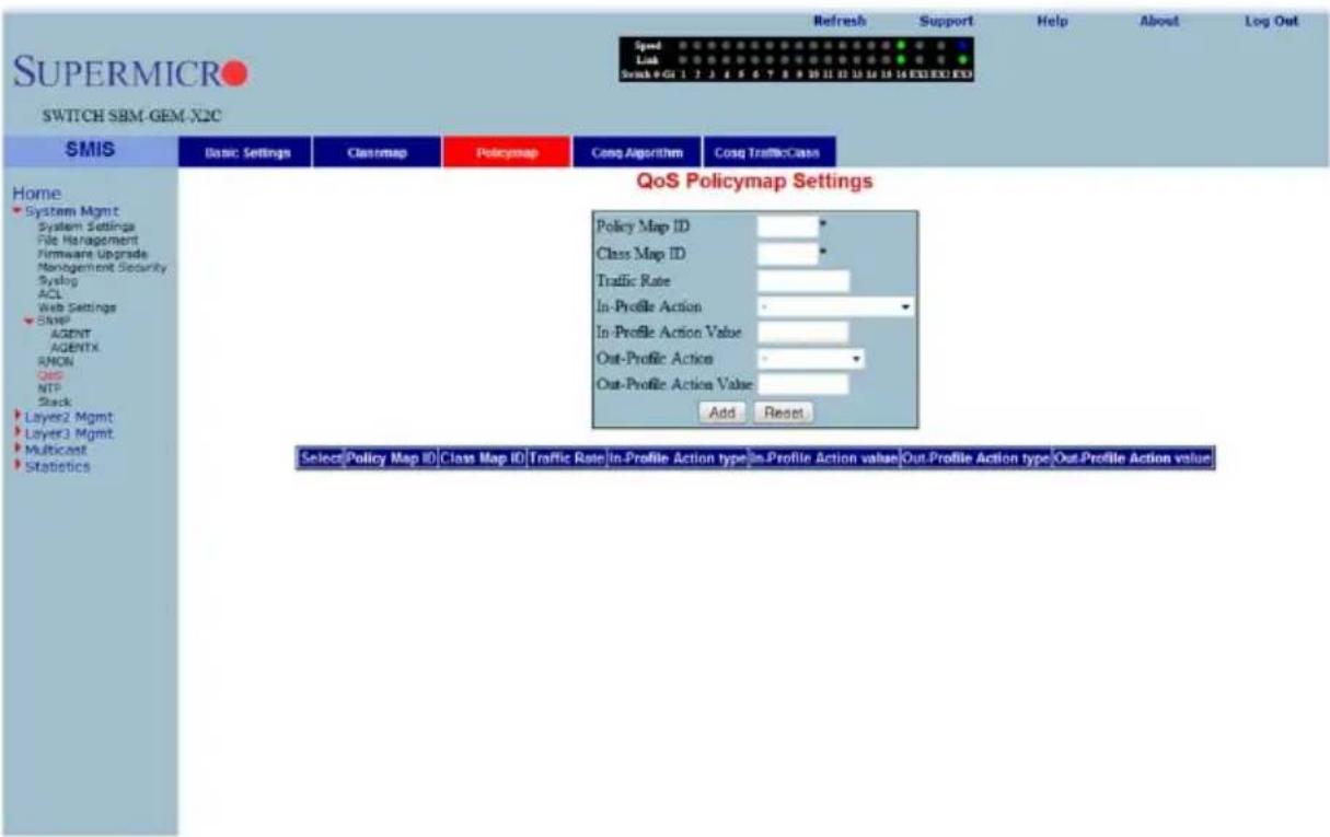
Clicking the POLICYMAP tab brings up the QOS POLICYMAP SETTINGS page (Figure 7-42), which is used to specify action for a specified classmap. The parameters for this page are shown in Table 7-31.
Table 7-31. QOS Policymap Settings Page Parameters
| Parameter Description | |
| Policy Map ID | This parameter specifies the unique ID for Policymap. The value ranges between 1 and 65535. |
| Class Map ID | This parameter specifies the CLASS MAP ID to associate with Policymap. |
| Traffic Rate This parameter specifies the T RAFFIC RATE of data that has to be applied. | |
| In-Profile Action | This parameter specifies the action to be applied on matched data, and can be specified as either Policy DSCP or Policy Precedence. |
| Out-Profile Action | This parameter specifies the action to be applied on out-of-profile data, and can be specified as either Policy DSCP or Drop. |
| In-Profile Action Value | The IN-PROFILE ACTION VALUE can be specified from 0 to 7 for DSCP, or from 0 to 63 for IP Precedence. |
| Out-Profile Action Value | The OUT-PROFILE ACTION VALUE can be specified as Drop or from 0 to 63 for DSCP. |
COSQ Scheduling Algorithm
Figure 7-43. COSQ Scheduling Algorithm Settings Page
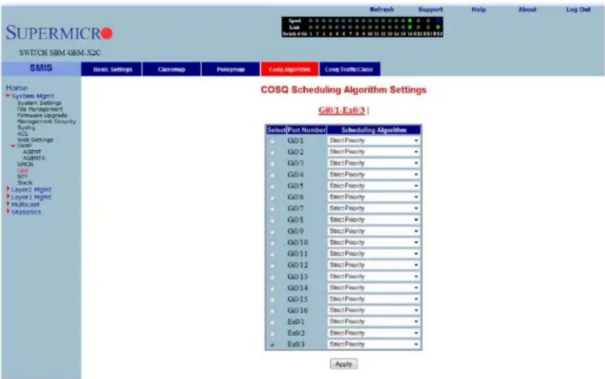
Clicking the COSQ ALGORITHM tab brings up the COSQ SCHEDULING ALGORITHM SETTINGS page (Figure 7-43), which allows you to choose the COSQ (Class of Service Queue) scheduling algorithm for every port. The parameters for this page are shown in Table 7-32.
Table 7-32. COSQ Scheduling Algorithm Settings Page Parameters
| Parameter Description | |
| Port Number | This list of ports allows you to select from the port index for your selected algorithm. |
| Scheduling Algorithm | The SCHEDULING ALGORITHM can be selected as one of the following:Strict PriorityRound RobinWeighted Round RobinWeighted Fair QueueinStrict Round RobinStrict Weighted Round RobinStrict Weighted Fair QueueingDeficit Round Robin |
COSQ Weight and Bandwidth Configuration
Figure 7-44. COSQ Weight and Bandwidth Configurations Page
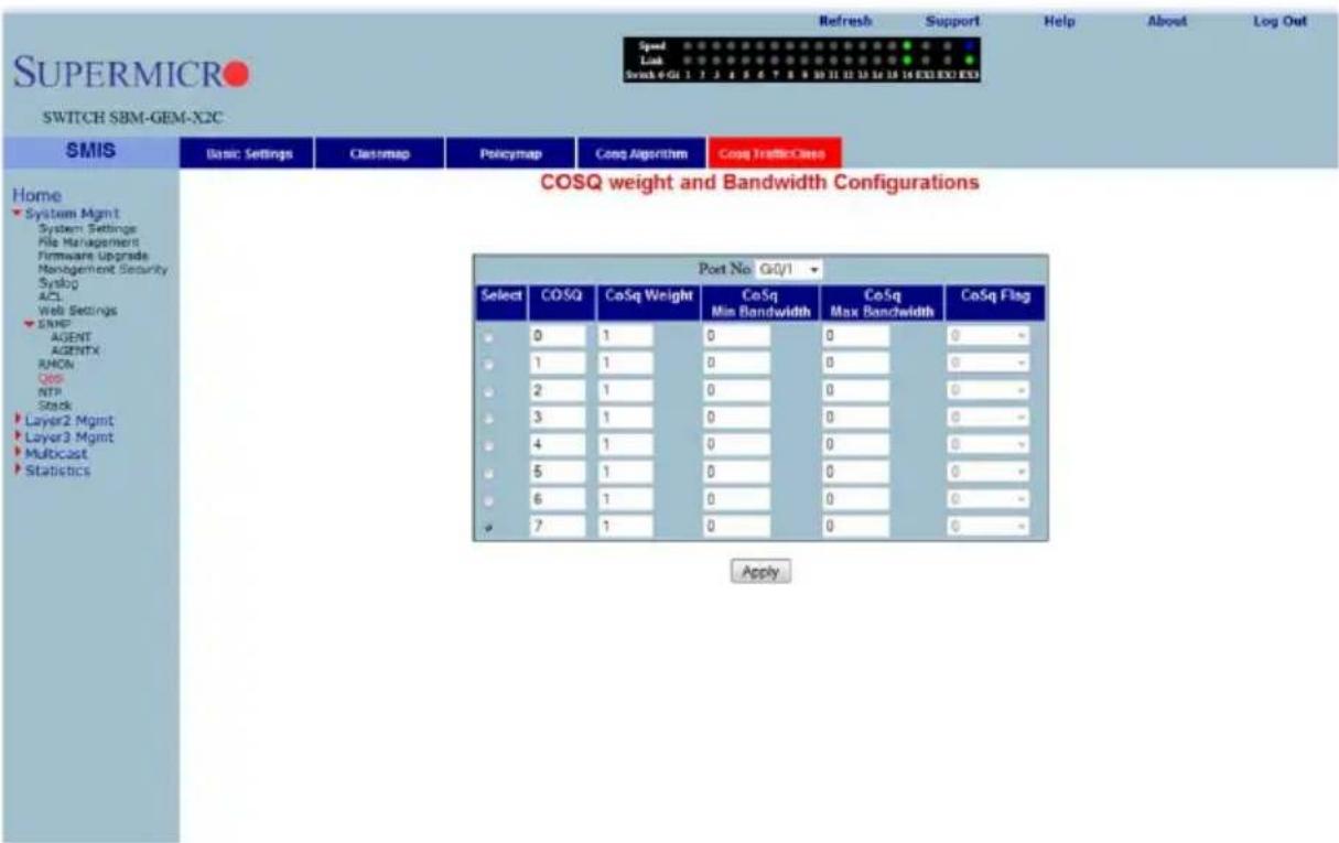
Clicking the COSQ TRAFFIC CLASS tab brings up the COSQ WEIGHT AND BANDWIDTH CONFIGURATIONS page (Figure 7-44), which allows you to configure the weight and bandwidth for CoS Queues. The parameters for this page are shown in Table 7-33.
Table 7-33. COSQ Weight and Bandwidth Configurations Page Parameters
| Parameter Description | |
| COSQ Queue | This parameter allows you to select between 0 to 7 for your COSQ QUEUE value. |
| COSQ Weight | This parameter allows you to select between 0 to 15 for your COSQ WEIGHT value. |
| COSQ Min Bandwidth | This parameter configures minimum bandwidth between 1 and 262143. |
| COSQ Max Bandwidth | This parameter configures maximum bandwidth between 1 and 262143. |
| COSQ Flag Use this parameter to set a flag for this queue. | |
NTP Settings
Figure 7-45. NTP Settings Page
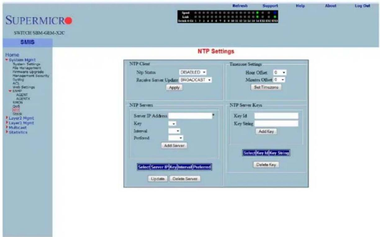
Clicking the NTP link brings up the NTP SETTINGS page (Figure 7-45), which configures the Network Time Protocol (NTP). The parameters for this page are shown in Table 7-34.
Table 7-34. NTP Settings Page Parameters
| Parameter Description | |
| NTP Client Settings | |
| NTP Status | This field enables or disables NTP in the switch. Configure the NTP SERVERS section to enable NTP. |
| Receive Server Update | The value for this parameter could be Broadcast or Unicast. To process the broadcast NTP updates from the server, choose the Broadcast option. |
| Timezone Settings | |
| Hour Offset This parameter allows you to enter an hour offset from GMT for local time. | |
| Minutes Offset | This parameter allows you to enter a minutes offset (after hour offset) from GMT for local time. |
| NTP Servers | |
| Server IP Address Use this parameter to enter the NTP server IP address. | |
| Key | Choose the key from the configured list. These keys are configurable in this page in the NTP SERVER KEYS section's fields. |
| Interval | This parameter allows you to choose the interval from the given list. |
| Preferred | This parameter allows you to choose the preferred server. Choose Yes if this server needs to be preferred over other configured NTP servers. You can add multiple NTP servers. |
| NTP Servers Keys | |
| Key ID | Use this parameter to select a number to identify the configured key strings. |
| Key String | Use this parameter to specify any string to be used as a key to handshake with NTP servers. |
Stack
The Supermicro Intelligent switch supports stacking of Supermicro switch units. Switch stacking is created by connecting switches in a daisy chain. One of the stacked switches is selected as a Master based on its configurations. The Master switch provides management support for the whole stack. Other switches in the stack are referred to as slave switches.

NOTE: Make sure all stacked switches are running the same version of firmware.
The Master switch manages the control plane traffic for all stacked switches. When the current master switch fails, the backup master is then selected as the current master. The Master selection algorithm is based on a priority configuration. If two switches have the same priority, the switch with the lowest MAC address is selected as the Master switch.
CX4 Cable Length
Stacking is supported with CX-4 cables only. The CX-4 cable used for stacking should be no more than 3-meters in length, because stacking internally runs at 12-Gbps and therefore requires a more robust signal than longer cable lengths might provide reliably. The industry standard stacking cable length is 3-meters.

NOTE: For stacking ports, you do not need to configure CX4 cable length. It is fixed as "short" for stacking ports.
When used for 10G Ethernet uplinks, the CX-4 ports can be from 1-meter to 12-meters in length; the maximum CX-4 cable length supported on Supermicro switches is 12-meters.
It is acceptable to use a 1-meter stacking cable for port 1 and a 12-meter uplink cable for port 2. You will only need to configure the long cable preference for port 2. Do this by selecting the Port Number in the CX4 CABLE LENGTH screen (Figure 7-46) and then selecting the "long" option.
Figure 7-46. Configuring CX4 Cable Length
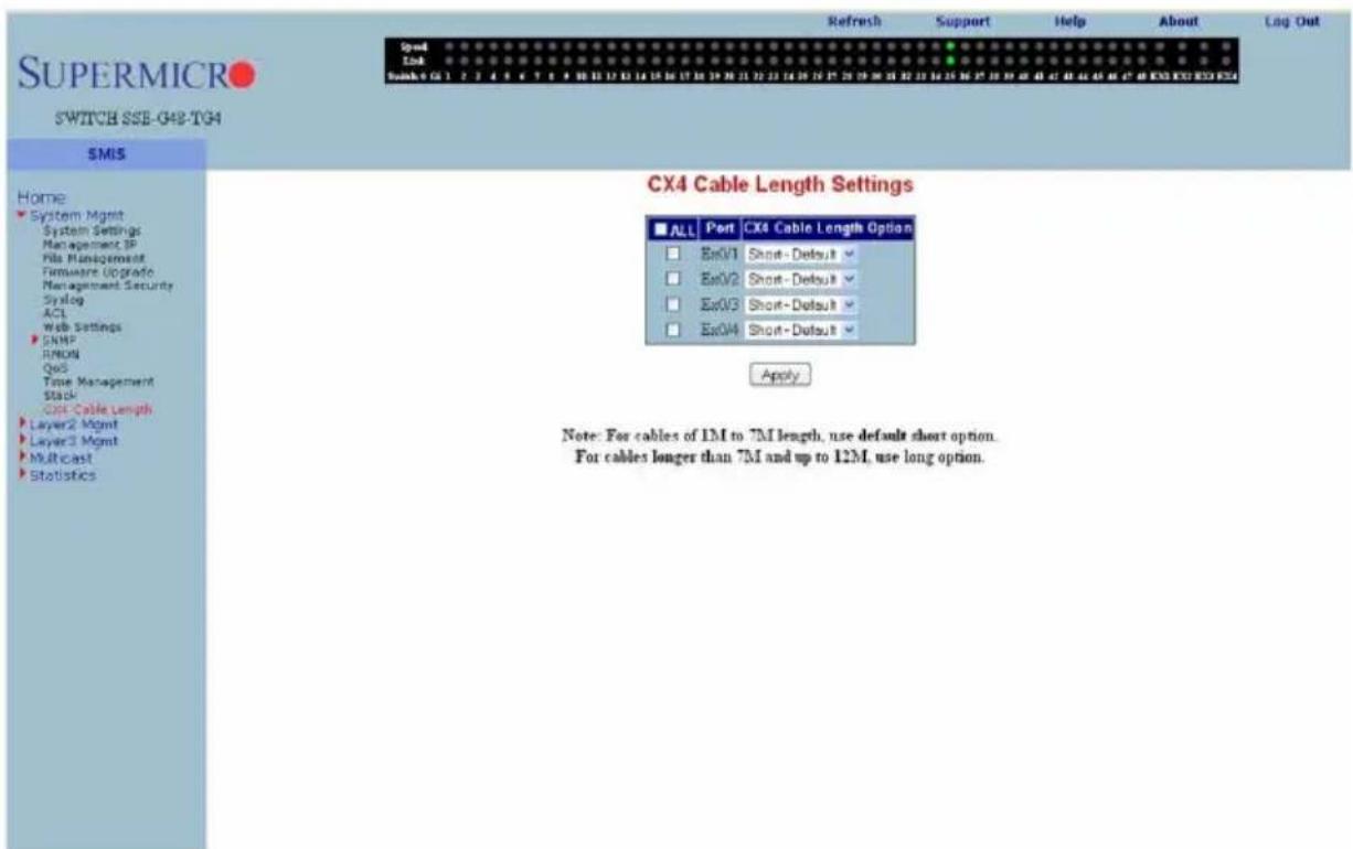
This configuration is done on an individual port basis. Thus, you can use "short" for one port and "long" for the other port. Alternatively you might use both "short" or, if neither are for stacking, both can be "long" cables.
Enabling Stacking
By default, Supermicro switches act as stand-alone switches. This stand-alone default facilitates using 10G Ethernet ports as Extreme Ethernet ports for uplinks.
When stacking is enabled the stacking ports are dedicated for stacking purposes. Stacking can be enabled using the command stack with the switch identifier and priority. The detailed command syntax is explained below.

NOTE: When stacking is enabled, the switch needs to be rebooted to make it effective.

NOTE: When a switch is acting as a stand-alone switch with stacking disabled, all physical interfaces are numbered as 0/1 to 0/n.
When the switch is in stacking mode, the interfaces are numbered as
In non-stacking mode, the switch ID is considered to be 0.
In the stacking mode, any firmware upgrade in the Master Switch will automatically initiate a firmware upgrade to all attached stack member switches. Firmware upgrade confirmation from stack member switches will be displayed in the Master Switch management interface.
Also in the stacking mode, the user can reload all stacked switches or any selected stack member switch from the master management interface.
The interface numbers change between stacking and non-stacking cases due to the switch ID. So configurations saved for stacking are not valid for non-stacking cases and vice versa.

NOTE: If you choose stacking using the stack command from a non-stacking case, and the configurations are already saved for restoring the switch, it will rename the configuration file by adding a suffix _nonstack and will not restore this file when the switch reboots with stacking enabled.
Similarly, if you choose non-stacking using the no stack command from the stacking case, and the configurations are already saved for restoring the switch, it will rename the configuration file by adding a suffix _stack and will not restore this file when the switch reboots with stacking disabled.
Adding Stacking Members
Connect the stacked switches using stacking cables. For better redundancy, connect the switches daisy-chained as shown in Figure 7-47. This chain connectivity helps to maintain stacking in case a single link or switch fails.
Before connecting switches in stacking, make sure stacking is enabled in all switches and that the switch identifier and priorities are all configured properly.
There is no other specific configuration required to add stacked switches. If two stacking-enabled switches connect through stacking cables, they form a stack.

NOTE: Do not use the same switch ID for multiple switches on the stack.
Figure 7-47. Switch Diagram
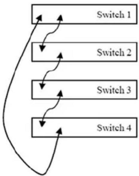
flowchart
graph TD
    A["Switch 1"] --> B["Switch 2"]
    B --> C["Switch 3"]
    C --> D["Switch 4"]
    D --> A
The SBM-GEM-X2C+ has four LEDs to display the stacking identifier. Due to the limited space available for LEDs, the stacking identifier is displayed in binary form using these four stacking LEDs.
| Stacking Identifier | Stacking ID LED 4 | Stacking ID LED 3 | Stacking ID LED 2 | Stacking ID LED 1 |
| 1 OFF OFF OFF ON | ||||
| 2 OFF OFF ON OFF | ||||
| 3 | O | F | F | O |
| 4 OFF ON OFF OFF | ||||
| 5 | O | F | F | O |
| 6 OFF ON ON OFF | ||||
| 7 OFF ON ON ON | ||||
| 8 ON OFF OFF OFF | ||||
| 9 | O | N | O | F |
| 10 ON OFF ON OFF | ||||
| 11 ON OFF ON ON | ||||
| 12 ON ON OFF OFF | ||||
| 13 ON ON OFF ON | ||||
| 14 ON ON ON OFF | ||||
| 15 ON ON ON ON | ||||
| 16 OFF OFF OFF OFF |

NOTE: In a stack only one switch can be configured as master. The slave switches will not allow you to configure anything except stacking disabled. To login to slave switches, use a login name as "stackuser" and password as "stack123".
Removing a stacked switch
To remove a switch from stacking follow the below recommended procedure.
- Disconnect stacking cables.
- Reboot the removed switch as a standalone switch.
- Disable stacking. Execute the "no stack" command.
- Reboot the switch again to operate as regular stand-alone switch.

NOTE: When a switch is moved from stacking to stand-alone mode, the saved stacking configurations can not be loaded in stand-alone mode. When stacking is disabled, the switch software renames the existing configuration file to avoid automatic restoration of stacking configurations on a stand-alone switch.
The following pages are available for configuring Stack settings;
- "Stack Configuration" on page 7-58
- "Stack Details" on page 7-59
- "Stack Counters" on page 7-61
Stack Configuration
Figure 7-48. Stack Configuration Page
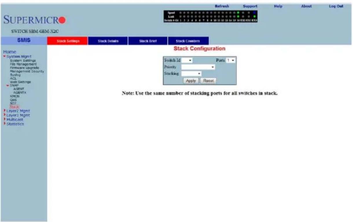
Clicking the STACK SETTINGS tab brings up the STACK CONFIGURATION page (Figure 7-48), which configures the stacking feature. The parameters for this page are shown in Table 7-35.
Table 7-35. Stack Configuration Page Parameters
| Parameter Description | |
| Switch ID | This parameter defines a switch identifier number for this switch. This identifier should be unique in the stack, since the number is used in referring all physical interfaces available in this switch.So for example, if this parameter is chosen as 2, the physical interfaces will be referred as Gi2/1 , Gi2/1 and so on.For non-stacking, stand-alone cases this switch ID is considered as zero. |
| Ports | This parameter represents the number of stacking ports. You can choose the number based upon your preferred stacking configuration and available CX4 ports. It is recommended that you use two CX4 ports as stacking ports to get redundancy. |
| Priority | This parameter chooses the priority for this switch in the Stacking Master selection. It could be configured as Preferred Master, Backup Master or Preferred Slave. |
| Stacking | This parameter enables or disables stacking.NOTE: Any change in stacking status requires a reboot of the switch. |
Stack Details
Figure 7-49. Stack Details Page
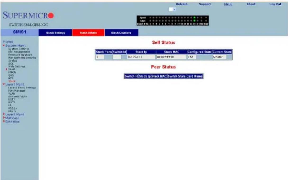
Clicking the STACK DETAILS tab brings up the STACK DETAILS page (Figure 7-49), which displays stacking details. The parameters for this page are shown in Table 7-36.
Table 7-36. Stack Details Page Parameters
| Parameter Description | |
| Self Status | |
| Stack Ports This is the number of stacking ports configured in this switch. | |
| Switch ID This parameter is used to specify the switch identifier of this switch. | |
| Stack IP | This parameter is used to specify the IP address of this switch. This IP address is used to communicate between stack member switches. |
| Stack MAC | This parameter is used to specify the MAC address of this switch. This MAC address is used to communicate between stack member switches. |
| Configured State This parameter is used to specify the priority of this switch. | |
| Current State | This parameter is used to specify the current status of this switch as Master or Slave. |
| Peer Status – The following parameters display information about all connected stack Slave switches. | |
| Switch ID This parameter is used to specify the switch identifier of the Slave switch. | |
| Stack IP | This parameter is used to specify the IP address of the Slave switch. This IP address is used to communicate between stack member switches. |
| Stack MAC | This parameter is used to specify the MAC address of the Slave switch. This MAC address is used to communicate between stack member switches. |
| Switch State | This parameter is used to specify the current status of the Slave switch. |
| Card Name This parameter is used to specify the type of Slave switch. | |
Stack Link Status
Figure 7-50. Stack Link Status Page
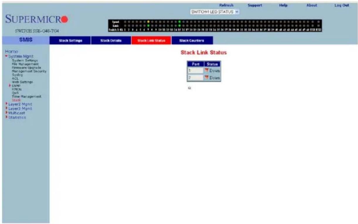
The STACK LINK STATUS page (Figure 7-50) displays the stack interface link status as "up" or "down".
Stack Counters
Figure 7-51. Stack Counter Details Page
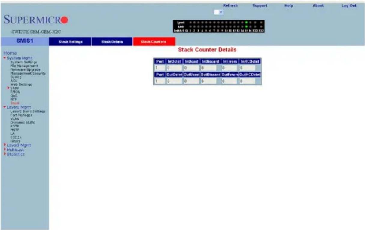
Clicking the STACK COUNTERS tab brings up the STACK COUNTERS DETAILS page (Figure 7-51), which displays statistics for stacking ports. The parameters for this page are shown in Table 7-37.
Table 7-37. Stack Counter Details Page Parameters
| Parameter Description | |
| Port This parameter displays | the stacking port identifier. |
| Received Statistics | |
| InOctet This parameter displays | the number of bytes received. |
| InUcast This parameter displays | the number of unicast packets received. |
| InDiscard | This parameter displays the number of received packets which were discarded. |
| InErrors This parameter displays | the number of packets received with errors. |
| InHCOctet This parameter displays | the number of bytes received with HC. |
| Transmit Statistics | |
| OutOctet This parameter displays | the number of bytes transmitted. |
| OutUcast This parameter displays | the number of unicast packets transmitted. |
| OutDiscard This parameter displays | the number of packets discarded in transmission. |
Table 7-37. Stack Counter Details Page Parameters (Continued)
| Parameter DescriptionOutErrors This parameter displays the number of packets transmitted got errors. |
| OutHCOctet This parameter displays the number of bytes transmitted with HC. |

NOTE: HC refers to the High Capacity value of the counter used. The regular counter is 32-bit. The HC counter is 64-bit.
Reload
Figure 7-52. System Settings Page – Reload
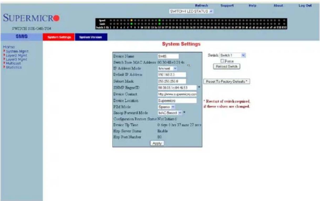
A "Switch Reload" function (Figure 7-52) is available in the SYSTEM SETTINGS page in the SYSTEM MANAGEMENT section.
You can use the SWITCH select option to choose the switch to reload, or you can select the ALL SWITCHES option to reload all stack member switches.
The FORCE check box provides an option to force a reload of the switch when the Master Switch is waiting for confirmation messages from slave switches for stacking configurations.
Click the RELOAD SWITCH button to reload the selected switch
7-5 Layer 2 Management
The LAYER2 MANAGEMENT page (Figure 7-53) has links to all pages with Layer2 controls.
Figure 7-53. Layer2 Management Page
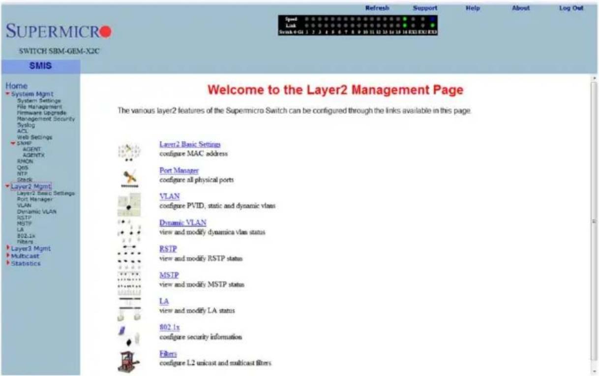
Layer 2 Basic Settings
Figure 7-54. MAC Address Table Settings Page
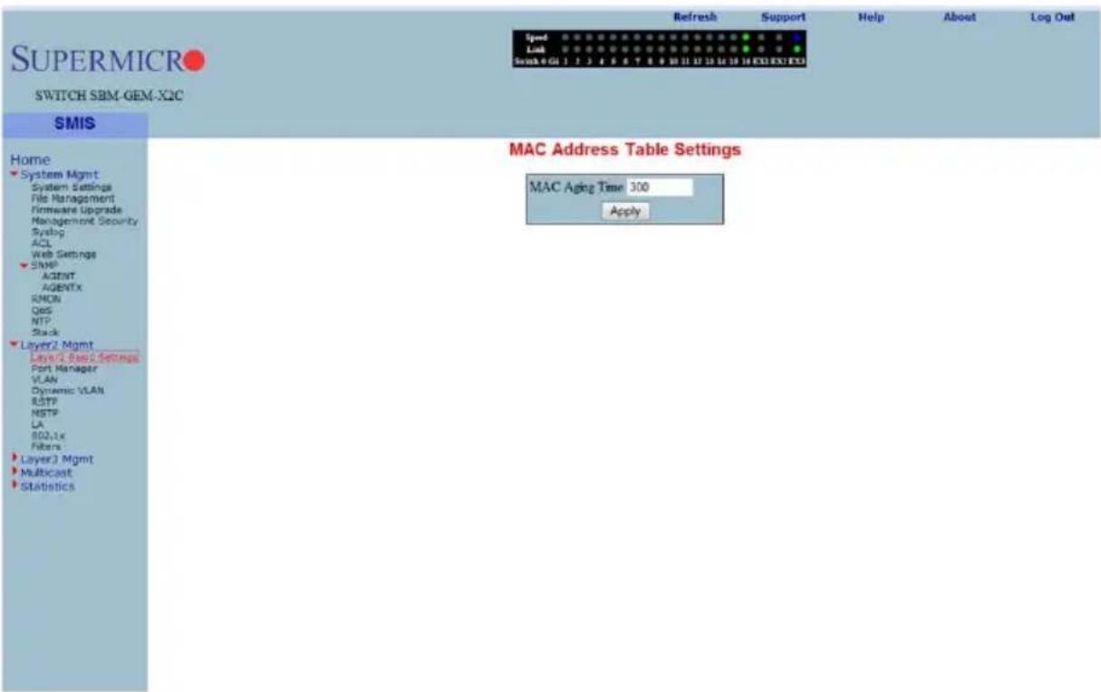
Clicking the LAYER2 BASIC STTINGS link brings up the MAC ADDRESS TABLE SETTINGS page (Figure 7-54), which gives you the option to change MAC aging time. MAC address confirmation can be done with this time interval.
Port Manager
The PORT MANAGER link has links to the following web pages:
- "Port Basic Settings" on page 7-65
• "Port Monitoring" on page 7-67
• "VLAN Traffic Class" on page 7-68
• "Port Control" on page 7-69
• "Rate Limiting" on page 7-70

NOTE: In all port based configuration pages, the port number group links are provided on the top.
In the normal standalone operation of the switch, there is only one link and the corresponding port configuration is displayed below it.
In case of stacking, multiple groups of port links are displayed. These links provide the configuration of ports from different stack member switches. To view the configuration of ports from a particular stack member switch, select the corresponding port links. For example, if three switches having switch identifier as 1, 2, and 3 are stacked together, the links will be as follows.
Gi1/1-Ex1/2 | Gi2/1-Ex2/2 | Gi3/1-Ex3/2
So to view the ports of switch 2, you need to select the Gi2/1-Ex2/2 link.
Port Basic Settings
Figure 7-55. Port Basic Settings Page
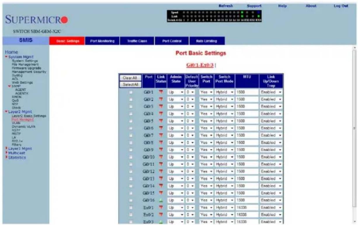
Clicking the BASIC SETTINGS tab brings up the PORT BASIC SETTINGS page (Figure 7-55), which allows you to configure port status and mode information. This page also helps configuring priority and MTU. The parameters for this page are shown in Table 7-38.
Table 7-38. Port Basic Settings Page Parameters
| Parameter Description | |
| Port This displays the port number. | |
| Link status | This column shows the physical link status as an UP or Down arrow. A green up arrow indicates that the status of the port is up, while the red down arrow indicates that the status of the port is down. |
| Admin State | This parameter allows you to administratively configure the admin state as Up or Down. |
| Default User Priority | This parameter allows you to set the priority from 0 to 7. |
| Switch Port | By default all ports are switch ports for layer 2 switching. To configure a port as a layer 3 routed port, choose No. |
| Switch Port Mode | Use this control allows to set the access mode as either Trunk or Hybrid. |
| MTU | This sets the MTU value. The Minimum is 90 and Maximum is 16338. A port must be administratively down in order to change the MTU. Jumbo frames of up to 9216 bytes are supported on 1G links. Jumbo frames of up to 16338 bytes are supported on 10G links. |
| Link Up/Down Trap | This parameter enables or disables SNMP trap generation for port up and down events. |
Port Monitoring
Figure 7-56. Port Monitoring Page
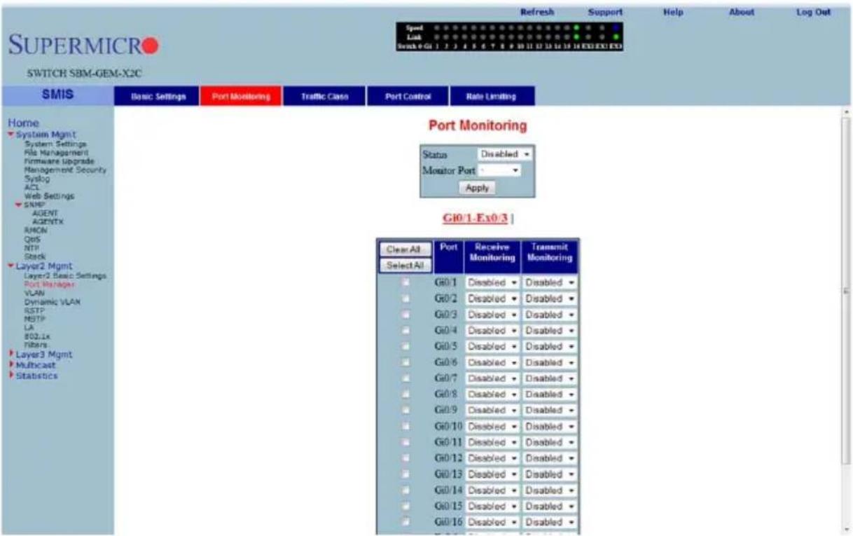
Clicking the PORT MONITORING tab brings up the PORT MONITORING page (Figure 7-56), which allows you to enable or disbale monitoring on port interface. The parameters for this page are shown in Table 7-39.
Table 7-39. Port Monitoring Page Parameters
| Parameter Description | |
| Status This parameter enables or disables the port monitoring. | |
| Port This displays the port number. | |
| Receive Monitoring This parameter enables or disables the receive monitoring. | |
| Trasmit Monitoring | This parameter enables or disables the transmit monitoring. |
VLAN Traffic Class
Figure 7-57. VLAN Traffic Class Mapping Page
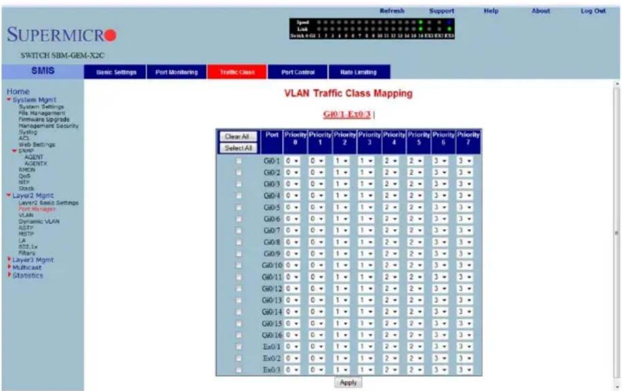
Clicking the TRAFFIC CLASS tab brings up the VLAN TRAFFIC CLASS MAPPING page (Figure 7-57), which allows you to map a priority to a traffic class. The parameters for this page are shown in Table 7-40.
Table 7-40. VLAN Traffic Class Mapping Page Parameters
| Parameter Description | |
| Port This displays the port number. | |
| Priority 0 This parameter chooses any traffic class 0 to 7 to map with priority 0. | |
| Priority 1 This parameter chooses any traffic class 0 to 7 to map with priority 1. | |
| Priority 2 This parameter chooses any traffic class 0 to 7 to map with priority 2. | |
| Priority 3 This parameter chooses any traffic class 0 to 7 to map with priority 3. | |
| Priority 4 This parameter chooses any traffic class 0 to 7 to map with priority 4. | |
| Priority 5 This parameter chooses any traffic class 0 to 7 to map with priority 5. | |
| Priority 6 This parameter chooses any traffic class 0 to 7 to map with priority 6. | |
| Priority 7 This parameter chooses any traffic class 0 to 7 to map with priority 7. | |
Port Control
Figure 7-58. Port Control Page
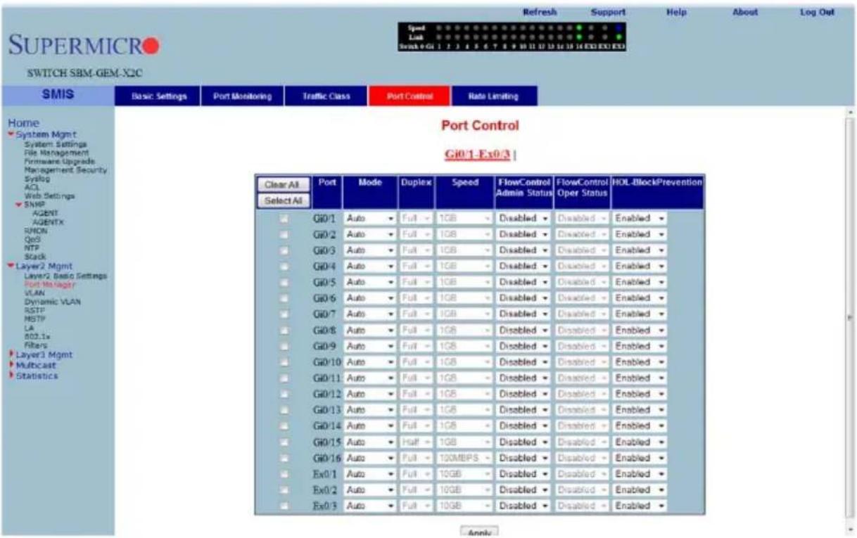
Clicking the PORT CONTROL tab brings up the PORT CONTROL page (Figure 7-58), which allows you to configure specific parameters of the port. You can choose between Auto-negotiation and No-negotiation for a port. If No-negotiation is chosen, then the speed of the link, FlowControl and duplex modes can be configured. The parameters for this page are shown in Table 7-41.
Table 7-41. Port Control Page Parameters
| Parameter Description | |
| Port This displays the port number. | |
| Mode | This parameter allows you to select either Auto Negotiation or No-negotiation. |
| Duplex | This parameter allows you to select either Full Duplex or Half Duplex. |
| Speed | This parameter allows you to select the speed as 10 Mbps, 100 Mbps or 1 G b p s . |
| Flow Control Admin Status | This parameter allows you to specify the Flow Control Admin Status as either Disabled, Trasmit Flow Control Enabled, Receive Flow Control Enabled or both Transmit and Receive Flow Control Enabled. |
| Flow Control Operation Status | This parameter displays the status of the flow control. |
| HOL Block Prevention | This parameter allows you to enable or disable Head of Line block prevention. |
Rate Limiting
Figure 7-59. Rate Limiting Page
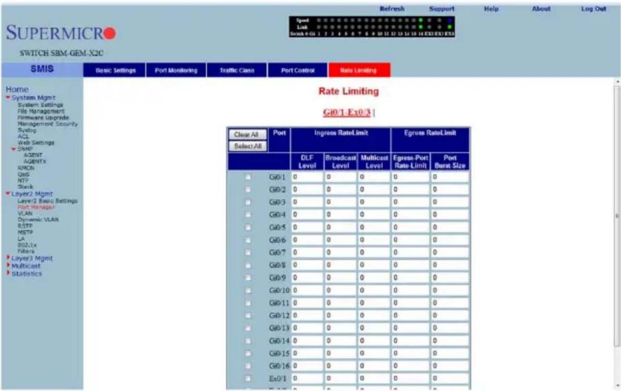
Clicking the RATE LIMITING tab brings up the RATE LIMITING page (Figure 7-59), which allows you to configure rate limiting for the port interface. The parameters for this page are shown in Table 7-42.
Table 7-42. Rate Limiting Page Parameters
| Parameter Description | |
| Port This displays the port number. | |
| The following parameters are configurable for Ingress Rate Limiting. | |
| DLF Level | This parameter allows you to specify the destination lookup failure packets per second. |
| Broadcast Level | This parameter allows you to specify the broadcast packets per second. |
| Multicast Level This parameter allows you to specify the multicast packets per second. | |
| The following parameters are configurable for Egress Rate Limiting. | |
| Egress Port Rate Limit | This parameter allows you to specify the egress limit of packets per second. |
| Egress Port Burst Size | This parameter allows you to specify the egress limit of packet burst size. |
VLAN
The VLAN link allows to configure the VLAN information. VLAN configuration information has been provided in the following pages:
• "VLAN Basic Settings" on page 7-71
- "Port Settings" on page 7-72
• "Static VLAN" on page 7-73
- "Protocol Group" on page 7-74
• "Port Protocol" on page 7-74
• "Vlan Port MAC Map" on page 7-75
• "Unicast MAC" on page 7-76
- "Wildcard" on page 7-77
• "Switch Port VLAN" on page 7-78
VLAN Basic Settings
Figure 7-60. VLAN Basic Settings Page
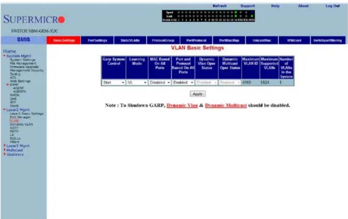
Clicking the BASIC SETTINGS tab brings up the VLAN BASIC SETTINGS page (Figure 7-60), which displays VLAN global configuration information. The parameters for this page are shown in Table 7-43.
Table 7-43. VLAN Basic Settings Page Parameters
| Parameter Description | |
| Garp System Control This parameter starts or shuts down GARP in the switch. | |
| Learning Mode | This parameter specifies the Learning Mode (Independent, Shared, Hybrid or VLAN Learning). |
| VLAN Version This parameter specifies the VLAN version supported. | |
| Maximum VLAN ID | This parameter specifies the largest (4094) valid VLAN ID, which this switch can accept, above which all will be discarded. |
| Maximum Supported VLANs | This parameter specifies the maximum number of VLANs that this device can scale. |
| Number of VLANs in the System | This parameter specifies the active number of VLANs configured in the device. |
| MAC Based on All Ports | This parameter enables or disables the per Port MAC based classification. |
| Port and Protocol Based on all Ports | This parameter enables or disables the per Port Protocol based classification. |
In addition, the BASIC SETTINGS page provides the configuration3 of Bridge Mode (Customer /Provider) and the priority for tunneled STP BPDUs. When you configure BRIDGE MODE TO PROVIDER, the Port Protocol based classification and MAC-based classification on all ports must be disabled.
Port Settings
Figure 7-61. VLAN Port Settings Page
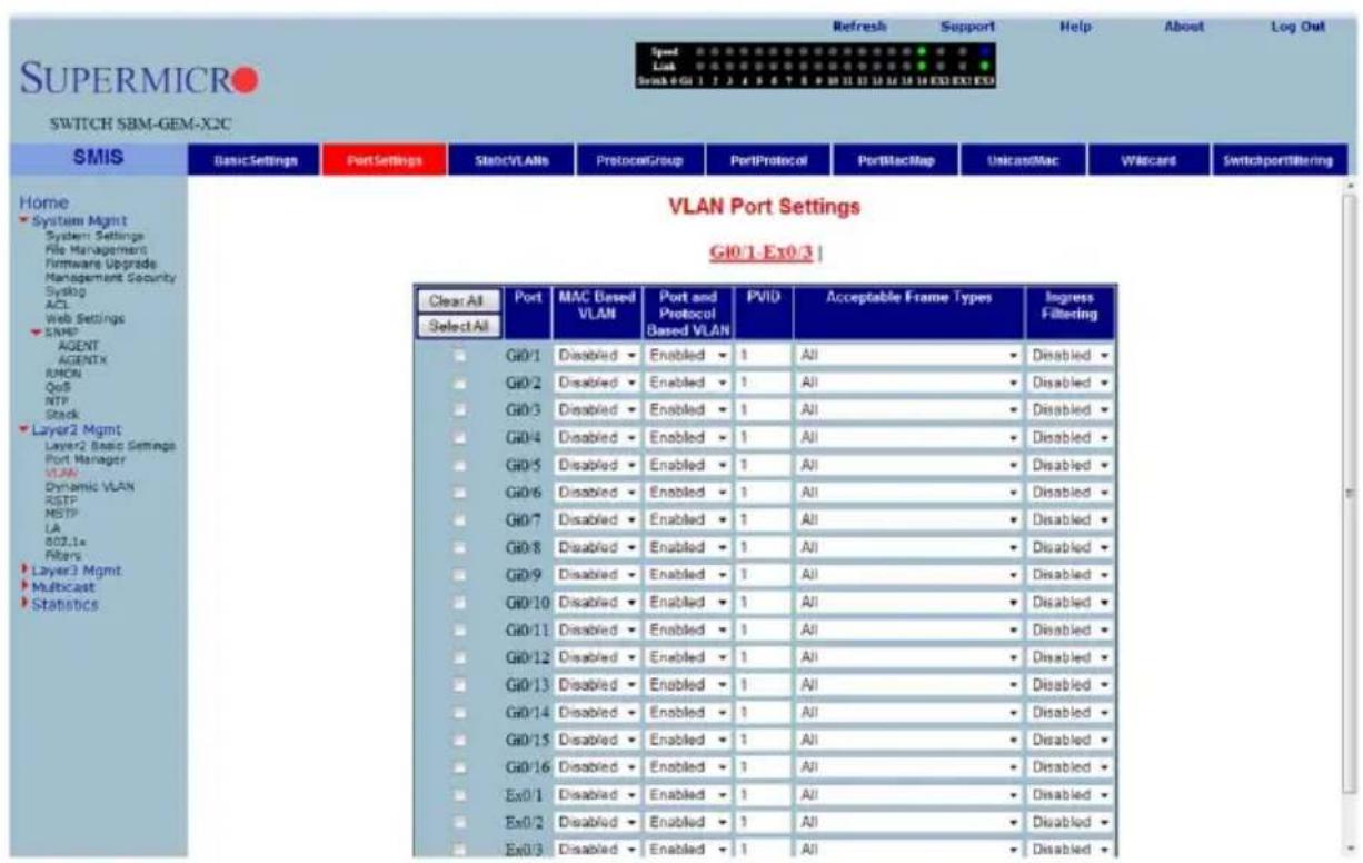
Clicking the PORT SETTINGS tab brings up the VLAN PORT SETTINGS page (Figure 7-61), which is used to associate the VLAN ID to the port for Port based VLAN classification.
While associating different ports to VLANs, you can also configure INGRESS FILTERING (at the port level) and ACCEPTABLE FRAME TYPES (accept Tagged Frame Alone or All frames).
The other configurations provided in this page are, enabling/disabling per Port MAC based classification and Port Protocol based classification, enabling/disabling of tunneling and enabling/disabling of STP BPDU Tunneling. To enable STP BPDU Tunneling on an interface, you must first enable tunneling on that interface.
Static VLAN
Figure 7-62. Static VLAN Configuration Page
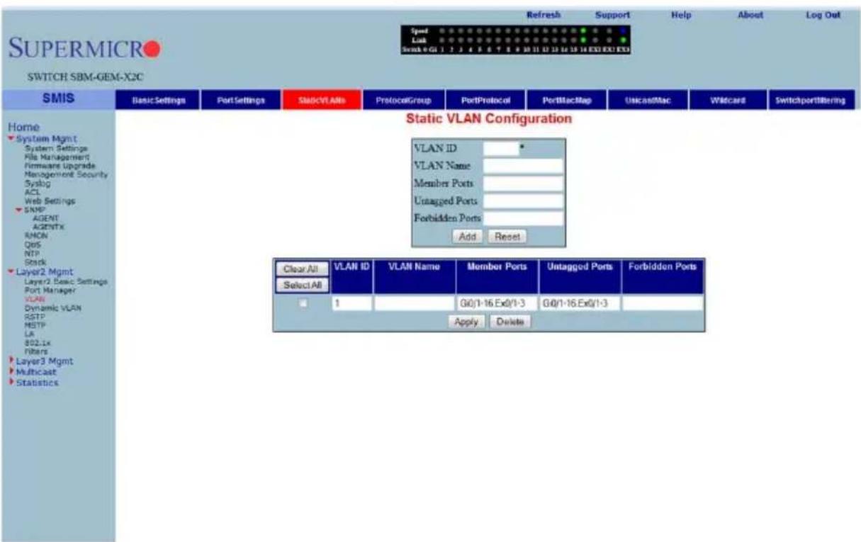
Clicking the STATIC VLANs tab brings up the STATIC VLAN CONFIGURATION page (Figure 7-62), which allows you to configure the VLAN related information statically.
Using the first table you can create new entries for uncreated VLANs. VLAN ID is the mandatory field in configuring a VLAN. You can also enter a VLAN NAME, MEMBER PORT LIST, UNTAGGED PORT and the FORBIDDEN PORTS for a VLAN.
The second table displays the VLAN configurations saved in the switch.
Protocol Group
Figure 7-63. VLAN Protocol Group Settings Page
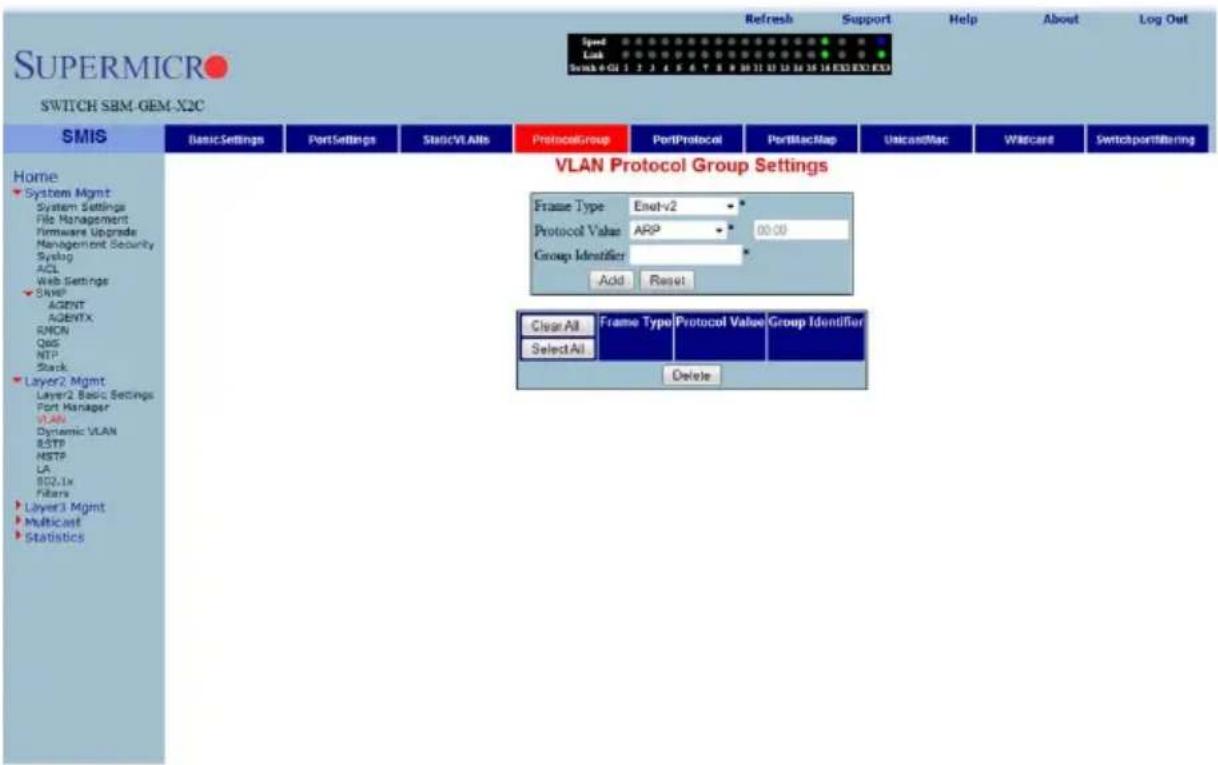
Clicking the PROTOCOL GROUP tab brings up the VLAN PROTOCOL GROUP SETTINGS page (Figure 7-63), which is used to map Protocol Templates to Protocol Group Identifiers.
The FRAME TYPE gives you the data-link encapsulation format. The PROTOCOL VALUE is the value of the protocol in a protocol template. The GROUP ID represents a group of protocols that are associated together.
Port Protocol
Clicking the Port PROTOCOL tab brings up the PORT VLAN PROTOCOL SETTINGS page (not shown), which displays a table used for Port and Protocol based VLAN classification. The GROUP ID designates a group of protocols in the Protocol Group Database. The VLAN ID is the ID associated with a group of protocols for each port.
Vlan Port MAC Map
Figure 7-64. VLAN Port MAC Map Settings Page
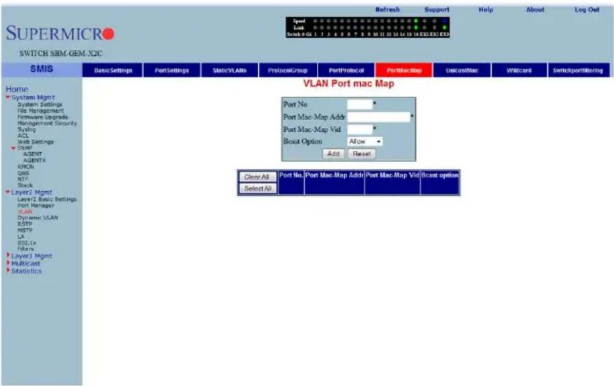
Clicking the PORT MAC MAP tab brings up the VLAN PORT MAC MAP page (Figure 7-64), which allows you to configure MAC based VLANs. The parameters for this page are shown in Table 7-44.
Table 7-44. VLAN Port MAC Map Page Parameters
| Parameter Description | |
| Port No This displays the port number. | |
| Port Mac-Map Addr This parameter specifies the Port MAC-Map address. | |
| Port Mac-Map Vid This parameter specifies the VLAN identifier for this MAC based VLAN | |
| Bcast Option | This parameter specifies the Broadcast option, which can be allowed or discarded. |
Unicast MAC
Figure 7-65. VLAN Unicast MAC Settings Page
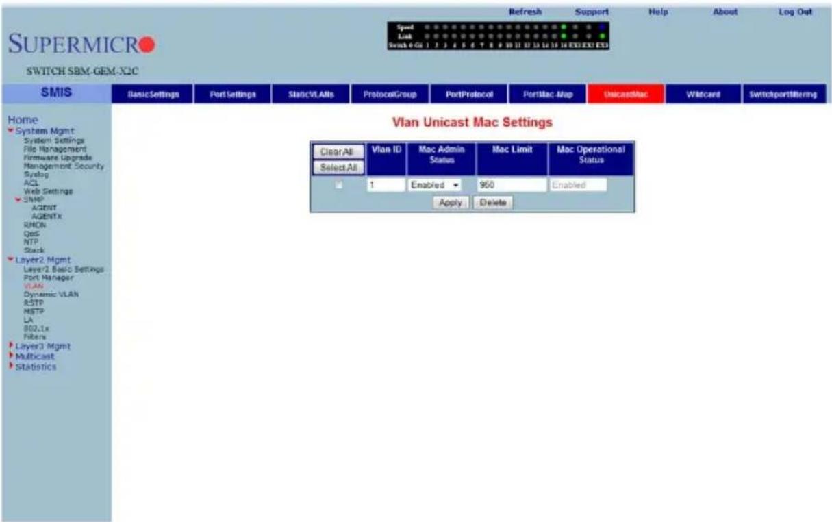
Clicking the UNICAST MAC tab brings up the VLAN UNICAST MAC SETTINGS page (Figure 7-65), which allows you to configure the various parameters for VLAN Unicast MAC settings. The parameters for this page are shown in Table 7-45.
Table 7-45. VLAN Unicast Mac Settings Page Parameters
| Parameter Description | |
| VLAN ID This parameter specifies the VLAN Identifier. | |
| MAC Admin Status | This parameter specifies the MAC administration status, which can be enabled or disabled. |
| MAC Limit This parameter indicates the MAC limit. | |
| MAC Operational Status | This parameter specifies the MAC operational Status, which can be enabled or disabled. |
Wildcard
Figure 7-66. Wildcard Settings Page
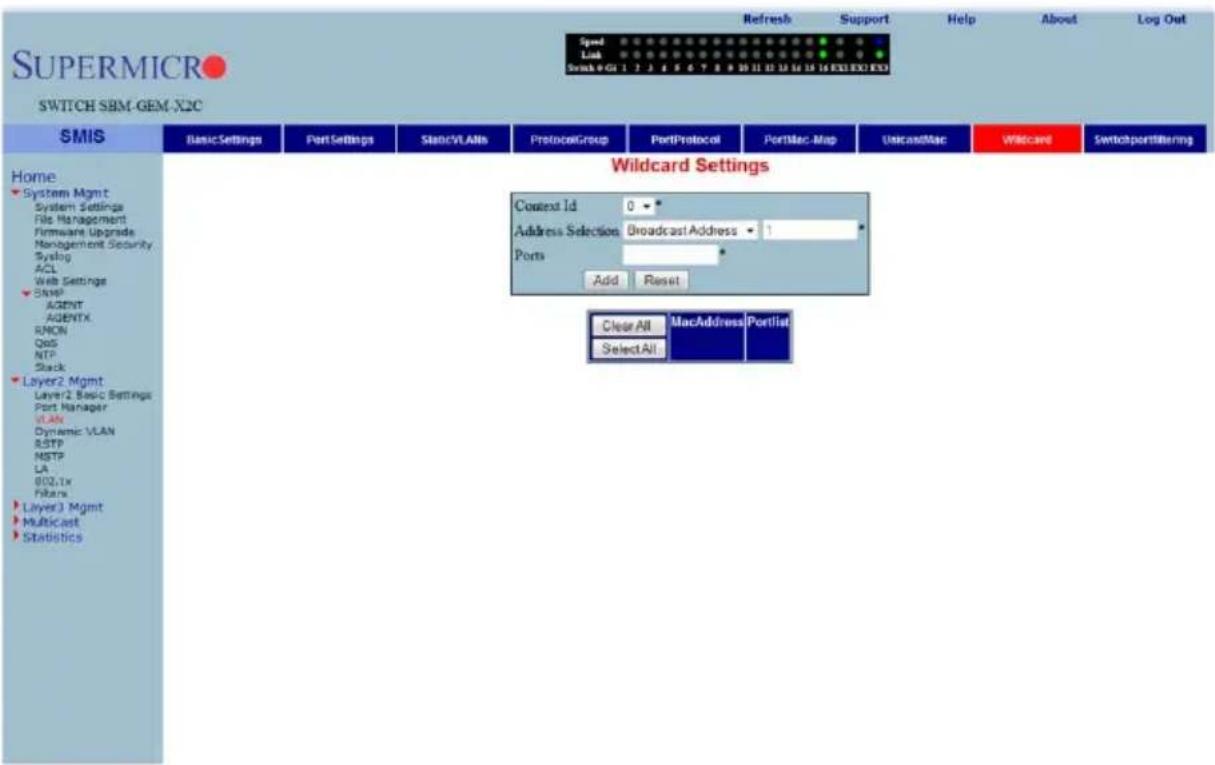
Clicking the WILDCARD tab brings up the WILDCARD SETTINGS page (Figure 7-66), which configures wildcard MAC addresses and ports for VLANs. The parameters for this page are shown in Table 7-46.
Table 7-46. Wildcard Settings Page Parameters
| Parameter Description | |
| Content ID | This parameter allows you to select the CONTENT ID. |
| Address Selection Use this parameter to select the address type. | |
| Ports This parameter allows you to enter a port. | |
Switch Port VLAN
Figure 7-67. SwitchPort Vlan Filtering Page
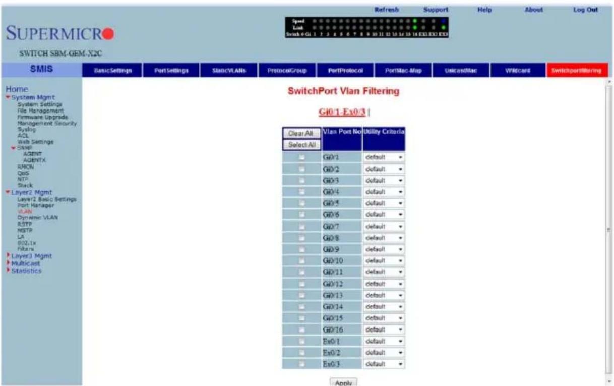
Clicking the SWITCH PORT FILTERING tab brings up the SWITCHPORT VLAN FILTERING page (Figure 7-67), which configures utility criteria for SwitchPort Vlan filtering. The parameters for this page are shown in Table 7-47.
Table 7-47. SwitchPort Vlan Filtering Page Parameters
| Parameter Description | |
| VLAN Port No. | This parameter displays the VLAN Port Number, which can be selected by the check box to the left of the column. |
| Utility Criteria | Use this parameter to select the utility criteria for the VLAN port selected. |
Dynamic Vlan
The Dynamic VLAN link allows you to configure the Dynamic VLAN information. Dynamic VLAN configuration information has been provided in the following pages
• "Dynamic VLAN Global Configuration" on page 7-79
- "Port Configuration" on page 7-80
• "GARP Timers" on page 7-81
Dynamic VLAN Global Configuration
Figure 7-68. Dynamic VLAN Global Configuration Page
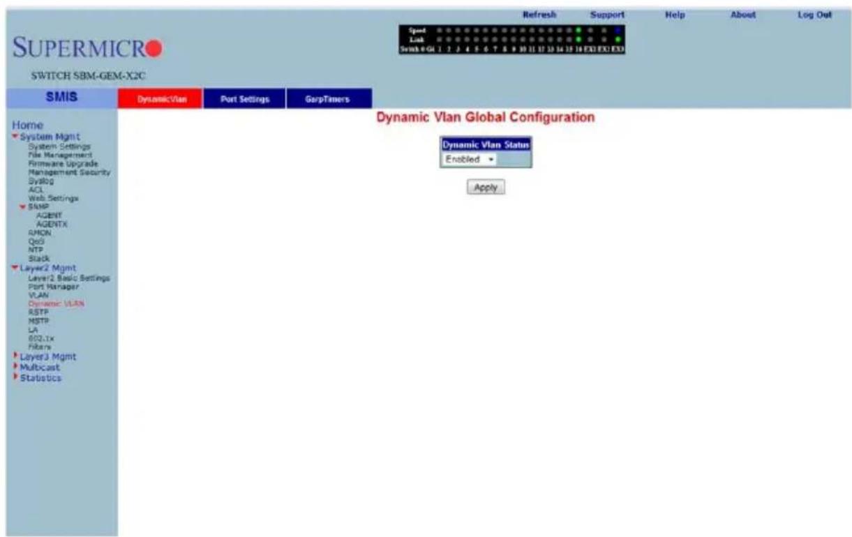
Clicking the DYNAMIC VLAN tab brings up the DYNAMIC VLAN GLOBAL CONFIGURATION page (Figure 7-68), which allows you to enable or disable Dynamic VLAN.
Port Configuration
Figure 7-69. Dynamic VLAN Port Configuration Page
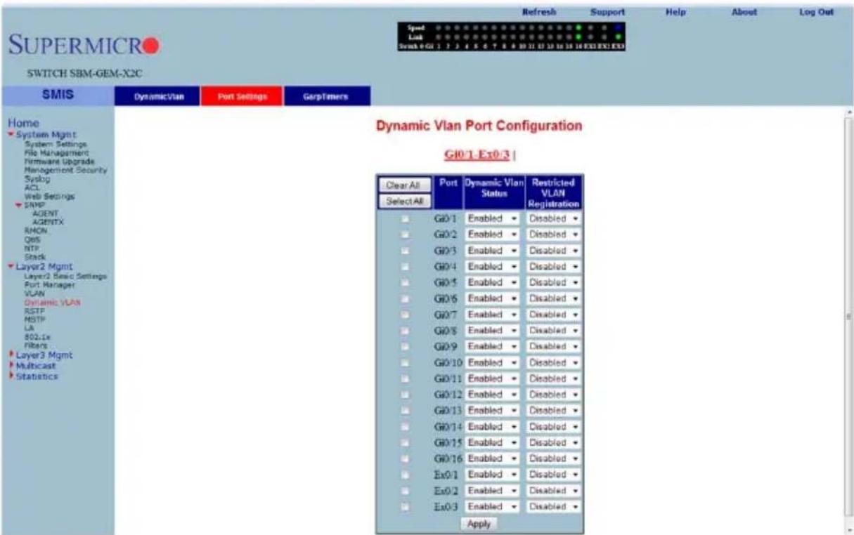
Clicking the PORT SETTINGS link brings up the DYNAMIC VLAN PORT CONFIGURATION page (Figure 7-69), which allows you to configure parameters for Dynamic VLAN ports. The parameters for this page are shown in Table 7-48.
Table 7-48. Dynamic VLAN Port Configuration Page Parameters
| Parameter Description | |
| Port | This parameter displays the Port Number, which can be selected by the check box to the left of the column. |
| Dynamic VLAN Status | Use this parameter to enable/disable the DYNAMIC VLAN STATUS. |
| Restricted VLAN Registration | This parameter allows you to enable/disable RESTRICTED VLAN REGISTRATION. |
GARP Timers
Figure 7-70. Garp Timers Configuration Page
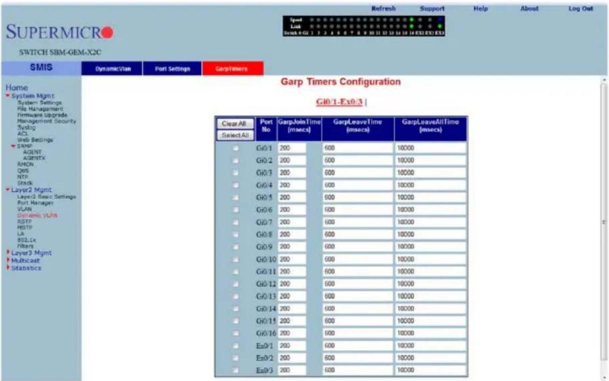
Clicking the GARP TIMERS tab brings up the GARP TIMERS CONFIGURATION page (Figure 7-70), which displays the various parameters for changing Garp times. The parameters for this page are shown in Table 7-49.
Table 7-49. Garp Timers Configuration Page Parameters
| Parameter Description | |
| Port No This parameter displays the Port Number. | |
| Garp Join Time (msecs) This parameter allows you to change the Garp Join Time. | |
| Garp Leave Time (msecs) This parameter allows you to change the Garp Leave Time. | |
| Garp Leave All Time (msecs) | This parameter allows you to change the Garp Leave All Time. |
RSTP
The RSTP link provides links to the following configuration pages:
• "RSTP Global Settings" on page 7-82
• "RSTP Basic Settings" on page 7-83
• "Port Settings" on page 7-84
- "Port Status" on page 7-85
RSTP Global Settings
Figure 7-71. Global Configuration Page
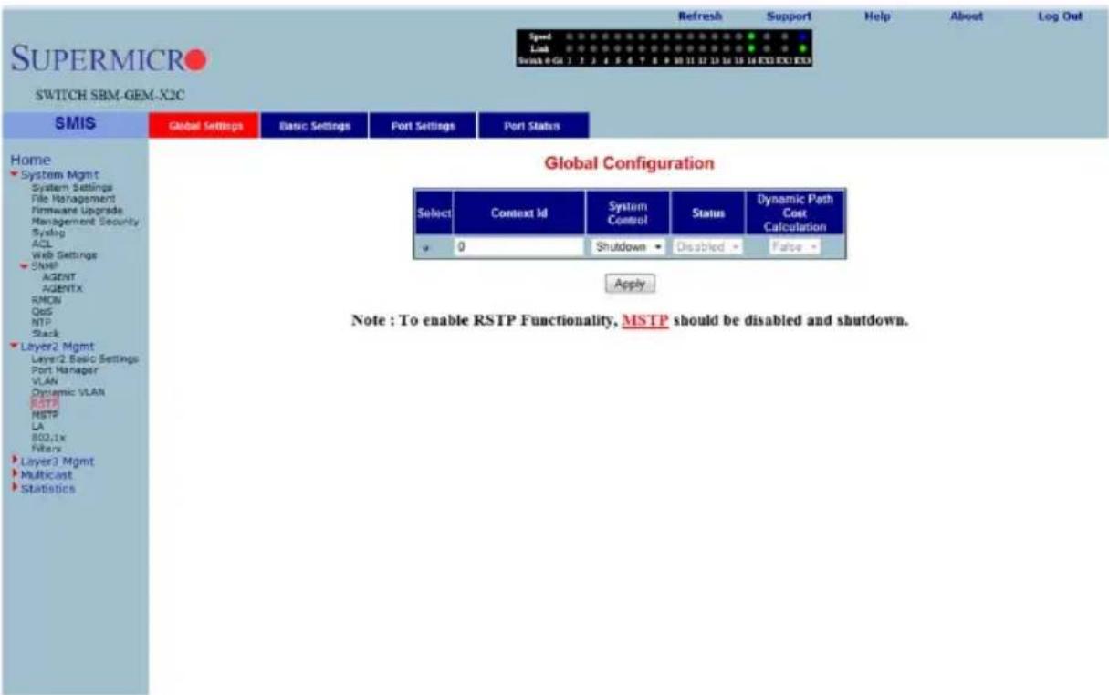
Clicking the GLOBAL SETTINGS tab brings up the GLOBAL CONFIGURATION page (Figure 7-71), which allows you to configure RSTP global parameters. The parameters for this page are shown in Table 7-50.
Table 7-50. Global Configuration Page Parameters
| Parameter Description | |
| System Control This parameter starts or Shutdown RSTP in the switch. | |
| Status | This parameter allows you to enable/disable the protocol at a global level on the switch. |
| Dynamic Path Cost Calculation | This parameter allows you to enable or disable the DYNAMIC PATH COST CALCULATION. |
RSTP Basic Settings
Figure 7-72. RSTP Configuration Page
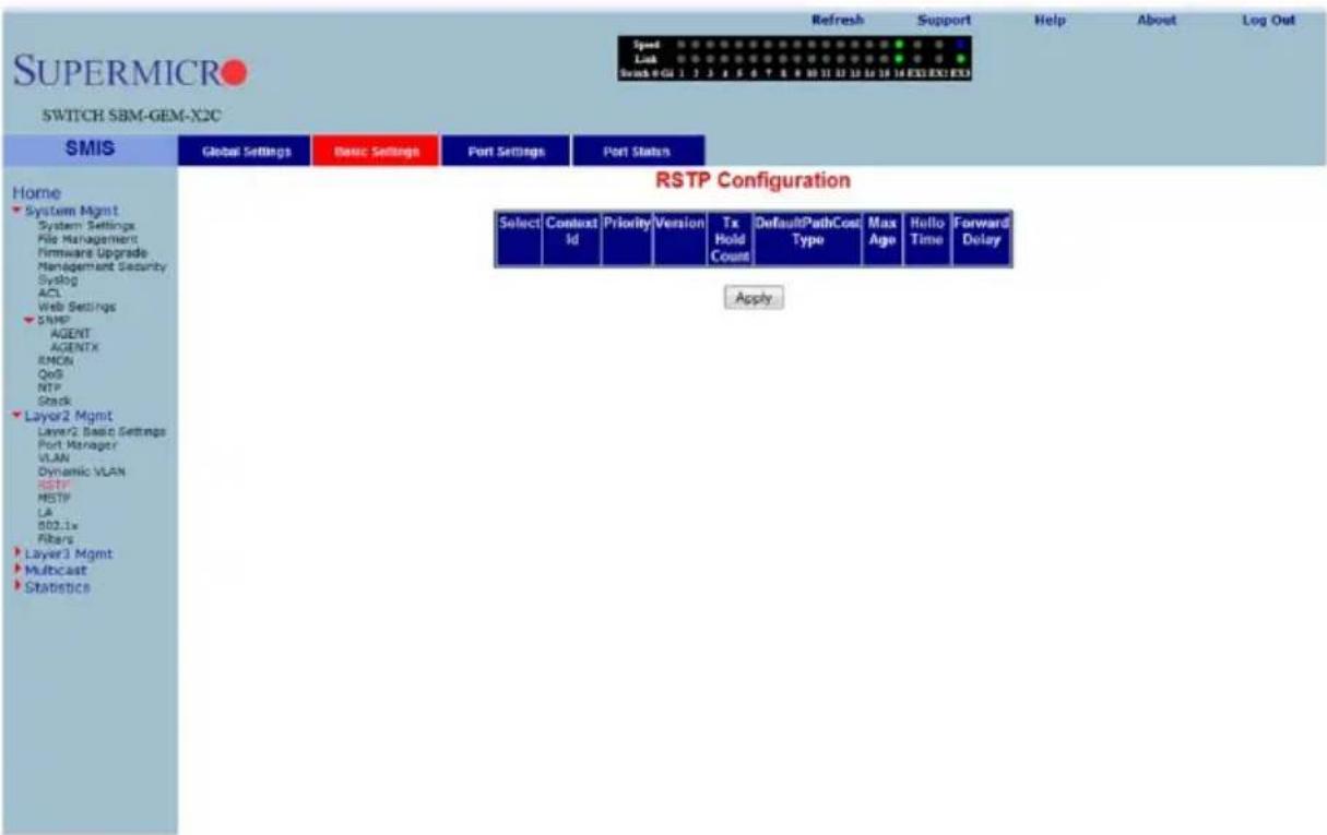
Clicking the BASIC SETTINGS tab brings up the RSTP CONFIGURATION page (Figure 7-72), which displays the various parameters for RSTP configuration. The parameters for this page are shown in Table 7-51.
Table 7-51. RSTP Configuration Page Parameters
| Parameter Description | |
| System Control This parameter allows you to start or shutdown RSTP in the switch. | |
| RSTP Status | This parameter allows you to enable/disable the protocol at a global level on the switch. |
| Compatibility | This parameter allows you to choose to run the protocol as an RSTP or STP compatible version. |
| Bridge Priority | This parameter specifies the BRIDGE PRIORITY, which can be used to select the root bridge. |
| Transmit Hold Count | This parameter specifies the maximum number of packets that can be sent in a given interval. This is configured to avoid flooding. |
| Default Path Cost Version | This parameter allows you to configure the path cost either as a 16-bit value or a 32-bit value. This is provided mainly for backward compatibility with STAP. |
Port Settings
Figure 7-73. Port Status Configuration Page
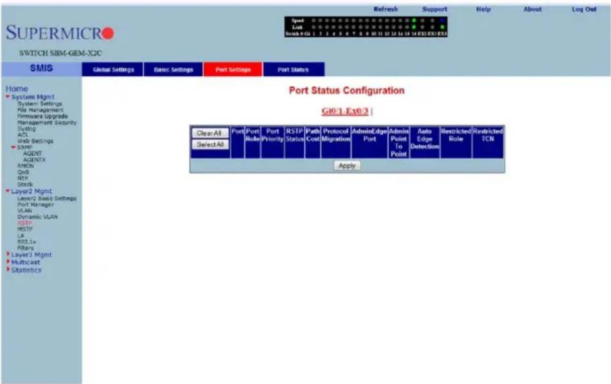
Clicking the PORT SETTINGS tab brings up the PORT STATUS CONFIGURATION page (Figure 7-73), which allows you to set the configuration per port related to RSTP. The parameters for this page are shown in Table 7-52.
Table 7-52. Port Status Configuration Page Parameters
| Parameter Description | |
| Port This parameter specifies the port identifier. | |
| Status | This parameter enables or disables the RSTP protocol status on a particular port. |
| Priority This parameter specifies the port priority used in role selection. | |
| Path Cost This parameter specifies the path cost associated with this port. | |
| Protocol Migration | This parameter controls the migration from RSTP to STP, if the other side of the switch runs STP. The migration takes place only if this is Enabled. |
| PortFast | This parameter must be configured, if the corresponding port is an edge port. |
| Point-to-Point | This parameter allows you to configure ports explicitly as Point-to-point (Force true), Non-point-to-point or leave the decision to be made Dynamically (from the AL or MAC layer). |
| Auto Edge Status | If this parameter is set to true, the edge port status is dynamically calculated. |
| Restricted Role | This parameter specifies the RESTRICTED ROLE status of the port. |
| Restricted TCN | This parameter indicates the RESTRICTED TCN status of the port. |
Port Status
Figure 7-74. RSTP Port Status Page
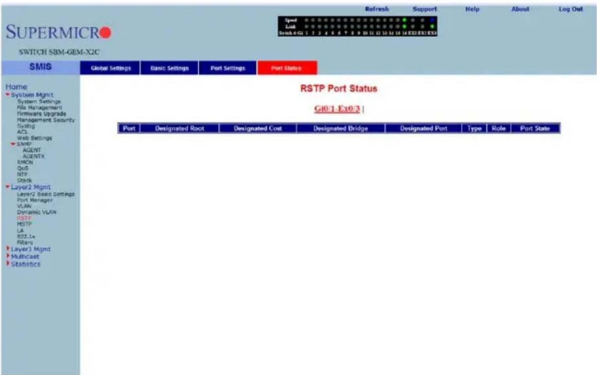
Clicking the PORT STATUS tab brings up the RSTP PORT STATUS page (Figure 7-74), which displays RSTP port specific information. The parameters for this page are shown in Table 7-53.
Table 7-53. RSTP Port Status Page Parameters
| Parameter Description | |
| Designated Root | This parameter specifies the unique Bridge Identifier of the bridge that is recorded as the root for the segment to which the port is attached. |
| Designated Cost | This parameter specifies the path cost of the Designated Port of the segment connected to this port. |
| Designated Bridge | This parameter specifies the Bridge Identifier of the bridge, which this port considers to be the Designated Bridge for this port's segment. |
| Designated PortType | This parameter specifies the Port Identifier of the port on the Designated Bridge for this port's segment.This parameter specifies the operational point-to-point status of the LAN segment attached to this port. It indicates whether a port is considered to have a Point-to-point connection or Shared Media. |
| Role | This parameter specifies the port's current role as defined by the Spanning Tree Protocol. |
| Port State | This parameter specifies the port's current state as defined by application of the Spanning Tree Protocol. |
MSTP
The MSTP link leads you to the following configuration pages:
• "MSTP Basic Settings" on page 7-86
• "MSTP Timers" on page 7-88
- "Port Configuration" on page 7-89
• "VLAN Mapping" on page 7-90
• "Port Settings" on page 7-91
• "CIST Port Status" on page 7-92
MSTP Basic Settings
Figure 7-75. Global Configuration Page
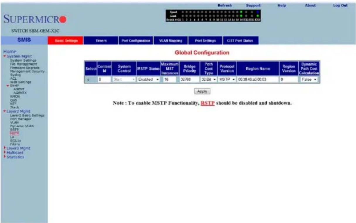
Clicking the BASIC SETTINGS tab brings up the GLOBAL CONFIGURATION page (Figure 7-75), which can access the MSTP global configuration. The parameters for this page are shown in Table 7-54.
Table 7-54. Global Configuration Page Parameters
| Parameter Description | |
| System Control | This parameter Starts or Shutdown MSTP in the switch. |
| MSTP Status | This parameter specifies the protocol that can be enabled/disabled at a global level on the switch using this field. |
| Compatibility | This parameter allows you to choose to run the protocol in MSTP, RSTP or an STP compatible version. |
| Bridge Priority | This parameter specifies the Priority value assigned to the bridge that is used to select the root bridge. |
| Transmit Hold Count | This parameter specifies the maximum number of packets that can be sent in a given interval. This is configured to avoid flooding. |
| Default Path Cost Version | This parameter allows you to configure the path cost either as a 16-bit value or a 32-bit value. This is provided mainly for backward compatibility with STAP. |
| Maximum Age (Seconds) | This parameter specifies the time period for which the information received in the RSTP BDPU is valid. |
| Forward Delay (Seconds) | This parameter specifies how fast a port changes its Spanning state when moving towards the Forwarding state. |
| Hop Counts (Seconds) | This parameter specifies the maximum number of bridges that a packet can cross before it will be dropped, to avoid infinite looping of the packets. |
| Region Name | This parameter specifies the name for the Region's configuration. By default, the region name will be equal to the Bridge MAC Address. |
| Region Version | This parameter specifies the version number of the configuration to be used. |
MSTP Timers
Figure 7-76. Timers Configuration Page
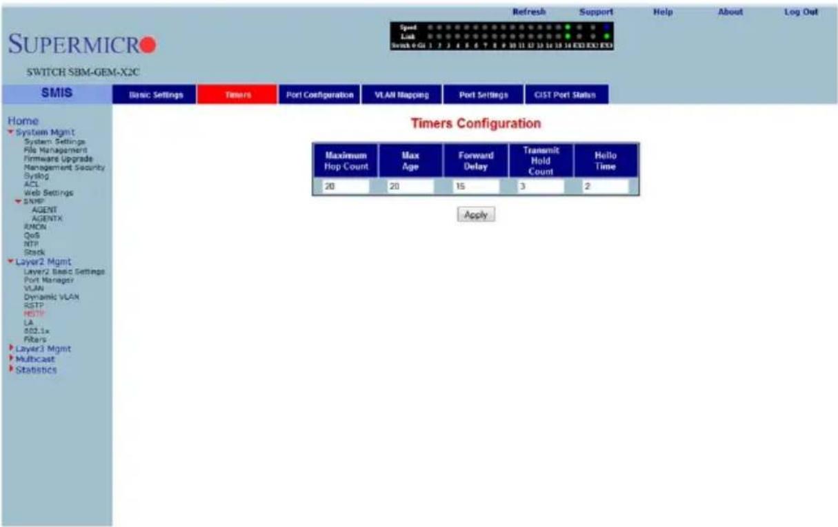
Clicking the TIMERS tab brings up the TIMERS CONFIGURATION page (Figure 7-76), which configures the time for MAXIMUM HOP COUNT, FORWARD DELAY, MAXIMUM AGE, TRANSMIT HOLD AGE and HELLO TIME.
Port Configuration
Figure 7-77. CIST Settings Page
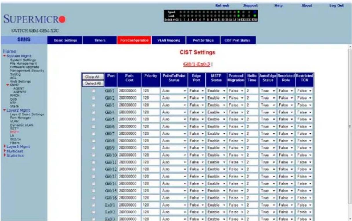
Clicking the PORT CONFIGURATION tab brings up the CIST SETTINGS page (Figure 7-77), which sets the configuration per Port related to MSTP. The parameters for this page are shown in Table 7-55.
Table 7-55. CIST Settings Page Parameters
| Parameter Description | |
| Port This parameter specifies the port identifier. | |
| Admin Status | This parameter specifies the MSTP protocol status that can be enabled/disabled on the particular port. |
| Priority This parameter specifies the port priority used in role selection. | |
| Path Cost This parameter specifies the path cost associated with this port. | |
| Protocol Migration | This parameter controls the migration among MSTP, RSTP and STP protocols, if the other side of the switch runs a different mode. Migration takes place only if this is enabled. |
| Edge Status | This parameter must be configured if the corresponding port is an edge port. |
| Point-to-Point Status | This parameter allows you to configure the ports explicitly as point-to-point (Force true), as a non-point-to-point port, or leave the decision to be made dynamically (from the AL or MAC layer). |
| Hello Time (Seconds) | This parameter specifies the administrative value of Hello Time for the port. |
| Auto Edge Status | If set to True, the edge port status will be dynamically calculated. |
| Restricted Role This parameter specifies the Restricted role status of the port. | |
| Restricted TCN This parameter indicates the Restricted TCN status of the port. | |
VLAN Mapping
Figure 7-78. VLAN Mapping Page
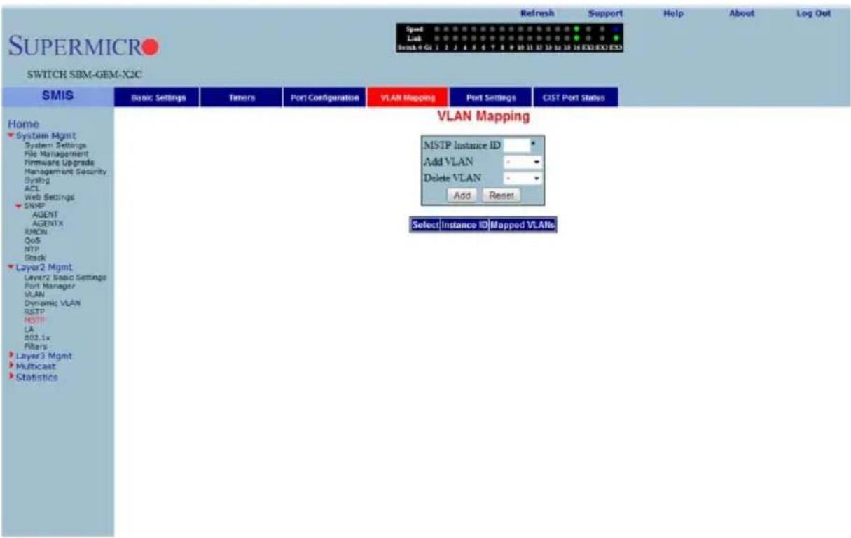
Clicking the VLAN MAPPING tab brings up the VLAN MAPPING page (Figure 7-78), whose table contains one entry for each instance of MSTP. The parameters for this page are shown in Table 7-56.
Table 7-56. VLAN Mapping Page Parameters
| Parameter Description | |
| MSTP Instance ID | This parameter specifies the Instance ID, which is the index of the table. |
| Map VLAN | This parameter specifies the list of VLANs to be mapped to this instance of the spanning tree. |
| Unmap VLAN | This parameter specifies the list of VLANs to be unmapped from this instance of the spanning tree. |
Port Settings
Figure 7-79. Port Settings Page
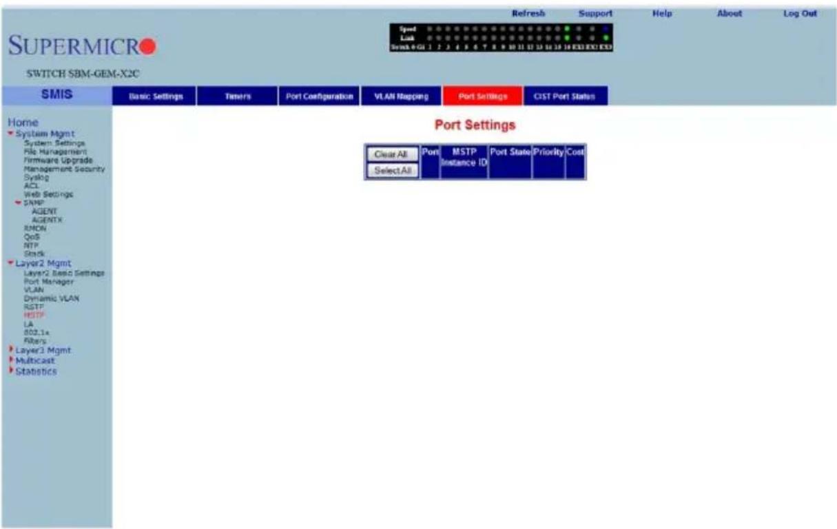
Clicking the PORT SETTINGS tab brings up the PORT SETTINGS page (Figure 7-79), which displays the various parameters for port settings. The parameters for this page are shown in Table 7-57.
Table 7-57. Port Settings Page Parameters
| Parameter Description | |
| Port | This parameter specifies the interface index of the port on which MSTP is being run. |
| MSTP Instance ID | This parameter specifies the instance ID of the STP that is associated with this instance. |
| Port State This parameter specifies the current state of the port. | |
| Priority This parameter specifies the priority related to this port. | |
| Cost | This parameter specifies the cost associated with this port, which will be added to the cost of any path that includes this port. |
CIST Port Status
Figure 7-80. MSTP CIST Port Status Page
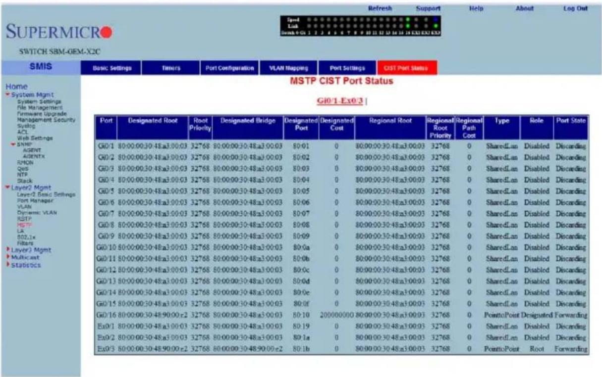
Clicking the CIST PORT STATUS tab brings up the MSTP CIST PORT STATUS page (Figure 7-80), which displays MSTP CIST port specific information. The parameters for this page are shown in Table 7-58.
Table 7-58. MSTP CIST Port Status Page Parameters
| Parameter Description | |
| Designated Root | This parameter specifies the unique Bridge Identifier of the Bridge recorded as the Root for the segment to which the port is attached. |
| Designated Bridge | This parameter specifies the Bridge Identifier of the bridge, which this port considers to be the Designated Bridge for this port's segment. |
| Designated Port | This parameter specifies the Port Identifier of the port on the Designated Bridge for this port's segment. |
| Designated Cost | This parameter specifies the path cost of the Designated Port of the segment connected to this port. |
| Regional Root | This parameter specifies the unique Bridge Identifier of the bridge recorded as the CIST Regional Root Identifier in the configuration BPDUs transmitted. |
| Regional Path Cost | This parameter specifies the contribution of this port to the path cost of paths towards the CIST Regional Root, which includes this port. |
| Type | This parameter specifies the operational point-to-point status of the LAN segment attached to this port. It indicates whether a port is considered to have a point-to-point connection or shared media. |
| Parameter DescriptionRole | This parameter specifies the ports current role as defined by the Spanning Tree Protocol. |
| Port State | This parameter specifies the port's current state as defined by the application of the Spanning Tree Protocol. |
LA
The LA link provides links to the following configuration pages:
• "LA Basic Settings" on page 7-94
- "Interface Settings" on page 7-95
• "Port Channel" on page 7-96
• "Port Settings" on page 7-97
• "Port State Info" on page 7-98
- "Load Balancing" on page 7-99
LA Basic Settings
Figure 7-81. LA Basic Settings Page
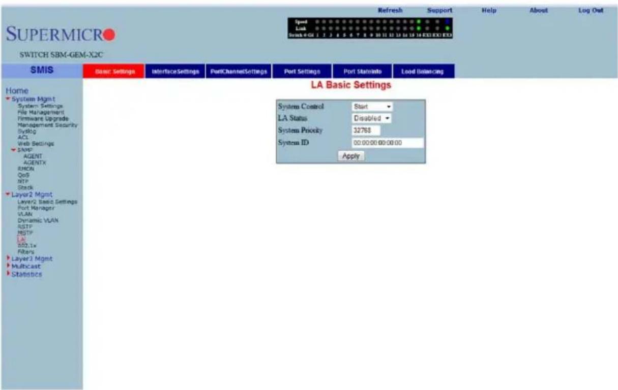
Clicking the BASIC SETTINGS tab brings up the LA BASIC SETTINGS page (Figure 7-81), which displays the various parameters for LA basic settings. The parameters for this page are shown in Table 7-59.
Table 7-59. LA Basic Settings Page Parameters
| Parameter Description | |
| System Control | This parameter Starts or Shutdown LA in the switch. |
| LA Status This is used to enable or disable LA in the switch. | |
| System Priority | This parameter specifies the priority value associated with the Actor's system ID. |
| System ID | This parameter specifies the Bridge MAC Address that is displayed. This is a read-only parameter. |
Interface Settings
Figure 7-82. Port Channel Interface Basic Settings Page
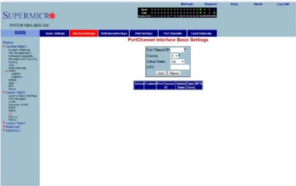
Clicking the INTERFACE SETTINGS tab brings up the PORT CHANNEL INTERFACE BASIC SETTINGS page (Figure 7-82), which allows you to configure port channels. The parameters for this page are shown in Table 7-60.
Table 7-60. Port Channel Interface Basic Settings Page Parameters
| Parameter Description | |
| Port Channel ID | This parameter specifies the identifier of the port channel interface. The valids values are between 1 to 65535. |
| Admin Status | This parameter administratively makes the port channel Up or Down. |
| MTU This parameter specifies the MTU value for this port channel. | |
Port Channel
Figure 7-83. LA Port Channel Settings Page
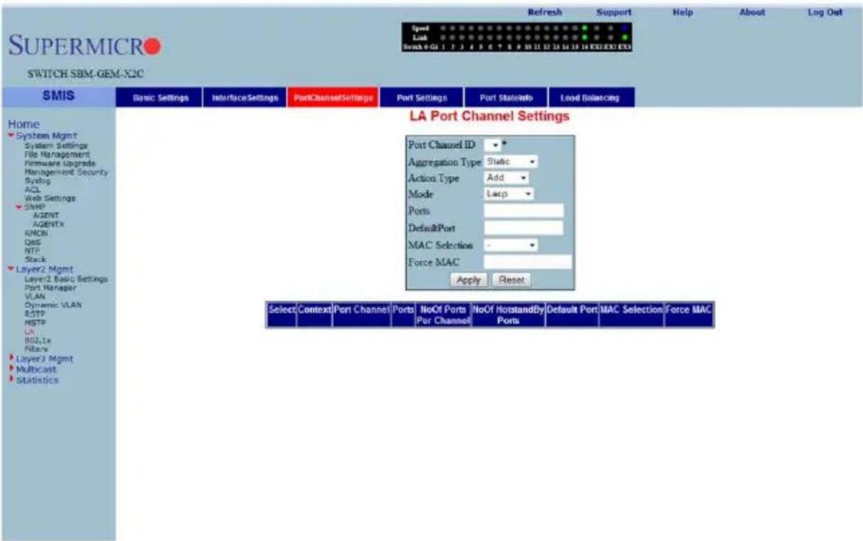
Clicking the PORT CHANNEL SETTINGS tab brings up the LA PORT CHANNEL SETTINGS page (Figure 7-83), which is used to edit the Port Channel configuration. The first table is for creating Port Channel interfaces while the second table is for editing the Port Channel configuration. The third table is used to display the Port Channels and to delete the existing Port Channels.
The parameters for this page are shown in Table 7-61.
Table 7-61. LA Port Channel Settings Page Parameters
| Parameter Description | |
| Port Channel ID This parameter specifies the identifier of the port channel interface. | |
| Action Type | This parameter specifies whether the port channel must be created or deleted. |
| Ports | This parameter specifies the interface indices that must be configured to be members of the Port Channel. |
| MAC Selection | This parameter specifies the mode by which the MAC address for the port channel is assigned. It can be dynamic or the user canForcethe selection of a specific MAC address. |
| Force MAC | This parameter specifies the MAC Address that is assigned to the port channel. For this, the MAC selection mode must beForce. |
Port Settings
Figure 7-84. LA Port Settings Page
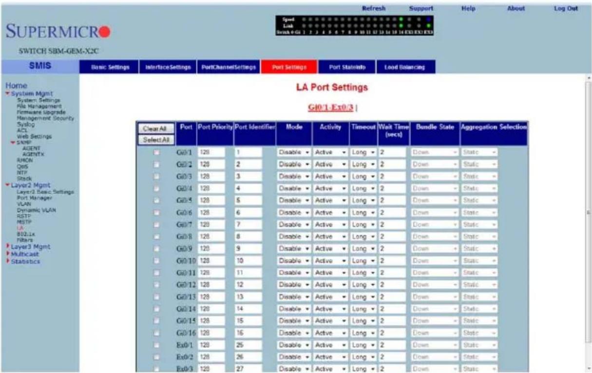
Clicking the PORT SETTINGS tab brings up the LA PORT SETTINGS page (Figure 7-84), which configures LA properties at a per-port level. The parameters for this page are shown in Table 7-62.
Table 7-62. LA Port Settings Page Parameters
| Parameter Description | |
| Port This parameter specifies the Interface Index. | |
| Port Priority This parameter specifies the priority value of the Port. | |
| Mode | This parameter specifies the various port modes, such as LACP, Manual or Disable. |
| Activity | This parameter specifies whether the Port LACP activity is Active or Passive. |
| Timeout | This parameter sets the time within which LACP PDUs must be received on a port to avoid timing out of the Aggregated Link. If a Long timeout is chosen then the ports will time out of the Port Channel in 90-seconds. If a Short timeout is chosen then the ports will time out of the Port Channel in 3-seconds. |
| Parameter DescriptionWait Time | This parameter configures the waiting time for a port after receiving Partner information and before entering aggregation. |
| Bundle State | This parameter indicates the current state of the port with respect to Link Aggregation. The possible states are:Up in Bundle- The port is an active member of the port channel.Up Individual- The port is not a member of any port channel but its Oper-Status is Up.Standby- The port is a member of the port channel but is currently in a standby state.Down- The port's Oper-Status is Down. |
Port State Info
Figure 7-85. LA Port State Machine Information Page
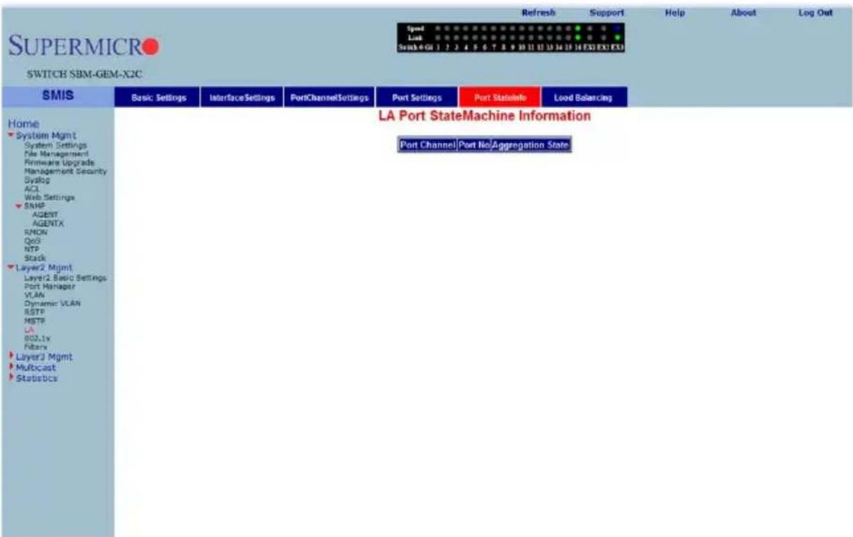
Clicking the PORT STATE INFO tab brings up the LA PORT STATE MACHINE INFORMATION page (Figure 7-85), which displays Link Aggregation state machine information. It displays the aggregation state information for every port channel.
Load Balancing
Figure 7-86. LA Load Balancing Policy Page
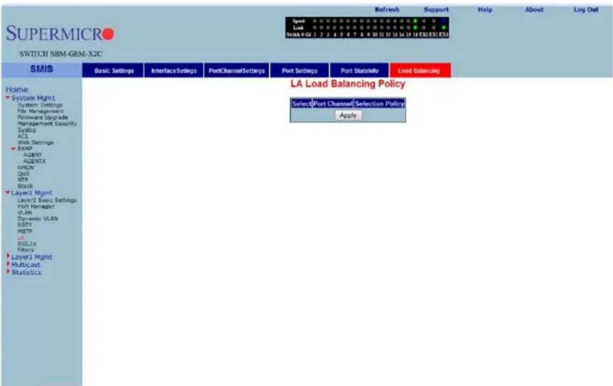
Clicking the LOAD BALANCING tab brings up the LA LOAD BALANCING POLICY page (Figure 7-86), which allows you to choose the selection policy for load distribution on the aggregated links.
The selection policy can be one of the following - Source MAC based, Destination MAC based, both Source and Destination MAC, Source IP address, Destination IP address or both IP addresses.
802.1x
The 802.1x link provides link to the following configuration pages:
• "Basic Settings" on page 7-100
• "Port Settings" on page 7-101
• "Timers" on page 7-103
- "Local AS" on page 7-104
• "MAC Session Info" on page 7-105
Basic Settings
Figure 7-87. 802.1x Basic Settings Page
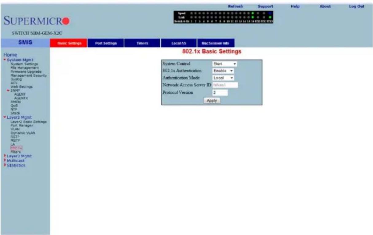
Clicking the BASIC SETTINGS tab brings up the 802.1x BASIC SETTINGS page (Figure 7-87), which displays the various 802.1x Basic Settings parameters. The parameters for this page are shown in Table 7-63.
Table 7-63. 802.1x Basic Settings Page Parameters
| Parameter Description | |
| System Control This parameter starts or shutdown 802.1x in the switch. | |
| 802.1x Authentication | This parameter allows enabling or disabling of the 802.1x based port security feature in the switch. |
| Authentication Server | This parameter specifies the Authentication Server Location as Remote or Local. |
| Network Access Server ID | This parameter specifies the Authenticator ID, which originates the Access-Request Packets. |
Port Settings
Figure 7-88. 802.1x Port Settings Page
| 802.1x Port Settings G10/1.Ex0/3 | | ||||||||||||
| SMIS Basic Settings Port Settings Timers Local AS MacSession Info | ||||||||||||
| Home System Mgmt System Settings File Management Firmware Upgrade Management Security Symbol ACL Web Settings SNMP AGENT AGENTX RMON QoS NTP Stack Layer2 Mgmt Layer2 Basic Settings Port Manager VLAN Dynamic VLAN RSTP MSTP LA 802.1x Filters Layer3 Mgmt Multicast Statistics | Clear All Select All | Port | Port Control | Access Control | Auth PortStatus | Supp PortStatus | Authentication Mode | Configured Control Direction | Operational Control Direction | AuthSM State | SuppSM State | Aut |
| G10/1 | ForceAuthorized | INACTIVE | Authorized | Unauthorized | Unauthorized | PortBased | Both | Both | Initialize | Disconnected | Fa | |
| G10/2 | ForceAuthorized | INACTIVE | Authorized | Unauthorized | Unauthorized | PortBased | Both | Both | Initialize | Disconnected | Fa | |
| G10/3 | ForceAuthorized | INACTIVE | Authorized | Unauthorized | Unauthorized | PortBased | Both | Both | Initialize | Disconnected | Fa | |
| G10/4 | ForceAuthorized | INACTIVE | Authorized | Unauthorized | Unauthorized | PortBased | Both | Both | Initialize | Disconnected | Fa | |
| G10/5 | ForceAuthorized | INACTIVE | Authorized | Unauthorized | Unauthorized | PortBased | Both | Both | Initialize | Disconnected | Fa | |
| G10/6 | ForceAuthorized | INACTIVE | Authorized | Unauthorized | Unauthorized | PortBased | Both | Both | Initialize | Disconnected | Fa | |
| G10/7 | ForceAuthorized | INACTIVE | Authorized | Unauthorized | Unauthorized | PortBased | Both | Both | Initialize | Disconnected | Fa | |
| G10/8 | ForceAuthorized | INACTIVE | Authorized | Unauthorized | Unauthorized | PortBased | Both | Both | Initialize | Disconnected | Fa | |
| G10/9 | ForceAuthorized | INACTIVE | Authorized | Unauthorized | Unauthorized | PortBased | Both | Both | Initialize | Disconnected | Fa | |
| G10/10 | ForceAuthorized | INACTIVE | Authorized | Unauthorized | Unauthorized | PortBased | Both | Both | Initialize | Disconnected | Fa | |
| G10/11 | ForceAuthorized | INACTIVE | Authorized | Unauthorized | Unauthorized | PortBased | Both | Both | Initialize | Disconnected | Fa | |
| G10/12 | ForceAuthorized | INACTIVE | Authorized | Unauthorized | Unauthorized | PortBased | Both | Both | Initialize | Disconnected | Fa | |
| G10/13 | ForceAuthorized | INACTIVE | Authorized | Unauthorized | Unauthorized | PortBased | Both | Both | Initialize | Disconnected | Fa | |
| G10/14 | ForceAuthorized | INACTIVE | Authorized | Unauthorized | Unauthorized | PortBased | Both | Both | Initialize | Disconnected | Fa | |
| G10/15 | ForceAuthorized | INACTIVE | Authorized | Unauthorized | Unauthorized | PortBased | Both. | |||||
Clicking the PORT SETTINGS tab brings up the 802.1x PORT SETTINGS page (Figure 7-88), which configures security information at the individual port levels. The parameters for this page are shown in Table 7-64.
Table 7-64. 802.1x Port Settings Page Parameters
| Parameter Description | |
| Port | This parameter specifies the Index of the port for which its fields (such as PORT CONTROL, PORT AUTHORIZATION STATUS, and so on) are configured. |
| Port Control | This parameter specifies the control values of the Authenticator Port. The control values can be:Force Authorize - All the traffic through this port will be allowed always.Force Unauthorize - All the traffic through this port will be blocked always.Auto - The 802.1x authentication process will be imposed over this port. |
| Port Authorization Status | This parameter specifies current status of the port either as Authorized or Un-Authorized. |
| Authentication Mode | This parameter specifies the configuration for selecting the AUTHENTICATION MODE to be Port Based. |
| Admin Control Direction | This parameter specifies whether security is to be imposed forIn - the incoming trafficBoth - both incoming and outgoing traffic |
| Operational Control Direction | This parameter specifies the current security status. |
| Port Initialize | This parameter specifies the initialization control for the port. Setting this value to True causes the port to be initialized. The value reverts to False once initialization is complete. |
| Maximum Authentication Request | This parameter specifies the maximum number of authentication requests that can be sent from the authenticator before getting a response from the supplicant. |
| Reauthentication | This parameter provides configuration to enable or disable the reauthentication mechanism on the port. |
Timers
Figure 7-89. 802.1x Timer Configuration Page
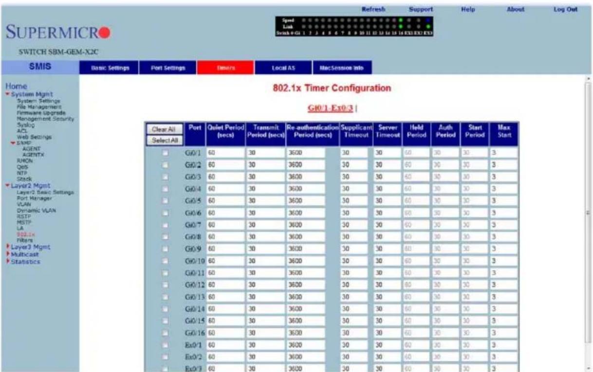
Clicking the TIMERS tab brings up the 802.1X TIMER CONFIGURATION page (Figure 7-89), which configures Timer parameters at the individual port level. The parameters for this page are shown in Table 7-13.
Table 7-65. 802.1x Timer Configuration Page Parameters
| Parameter Description | |
| Port | This parameter is the index of the port for which fields such as QUIET PERIOD, TRANSMIT PERIOD, and such are configured. |
| Quiet Period (Seconds) | This parameter specifies the duration for which the authenticator will be silent and will not attempt to acquire a supplicant. It can be configured to any value in the range from 1 to 65535 seconds. |
| Transmit Period (Seconds) | This parameter specifies the time period used by the Authenticator State machine to define when the EAPOL PDU is to be transmitted. It can be configured to any value in the range from 1 to 65535 seconds. |
| Re-authentication Period (Seconds) | This parameter specifies the time between periodic re-authentication of the supplicant. |
Local AS
Figure 7-90. Local Authentication Server Configuration Page
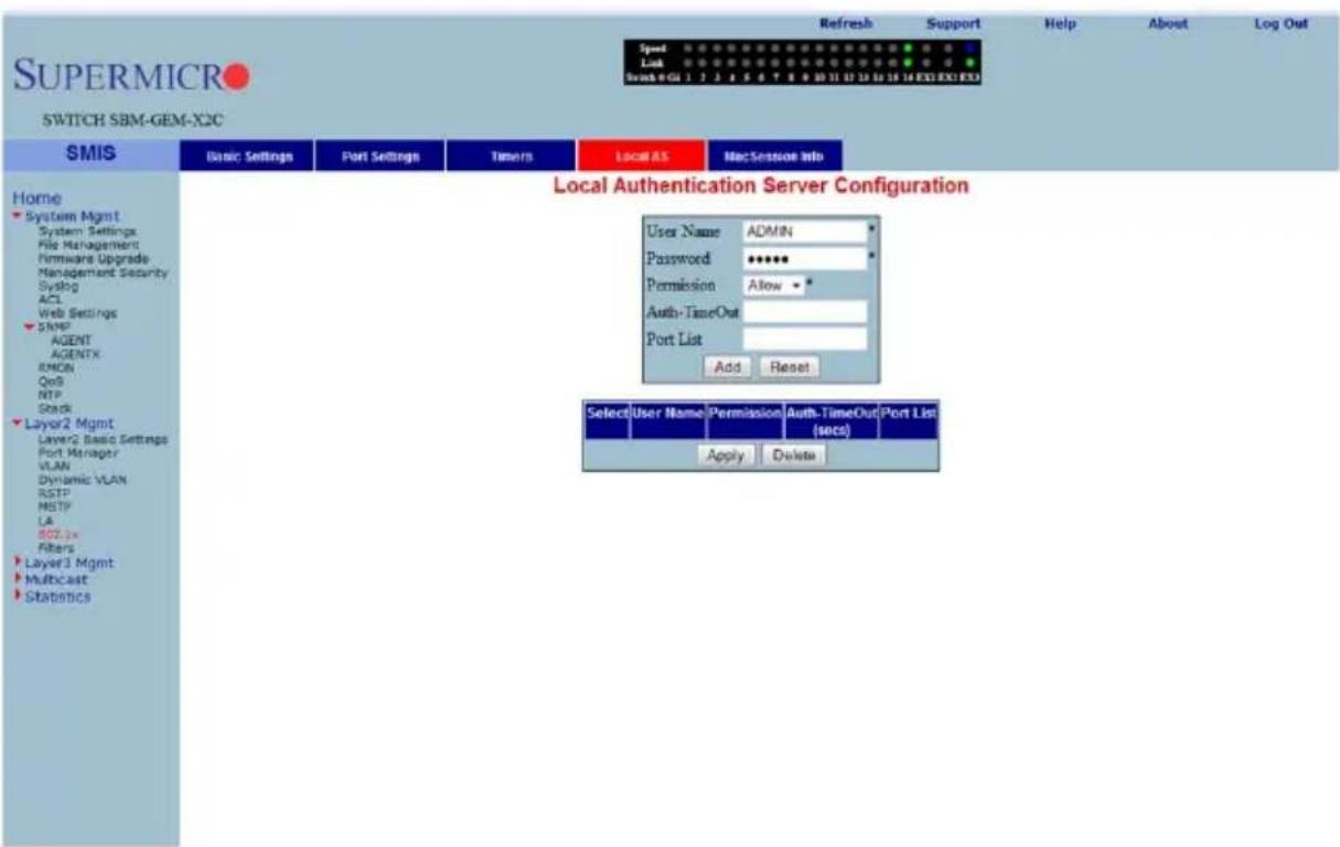
Clicking the LOCAL AS tab brings up the LOCAL AUTHENTICATION SERVER CONFIGURATION page (Figure 7-21), which configures Local Authentication Server information. The parameters for this page are shown in Table 7-13.
Table 7-66. Local Authentication Server Configuration Page Parameters
| Parameter Description | |
| User Name | This parameter specifies the identity of the user who is seeking authentication, and is set by a string of not more than 20 printable characters. |
| Password | This parameter specifies the password specific to the user name, and is set by a string of not more than 20 printable characters. |
| Permission | This parameter represents the allowance and denial of access. The values that can be configured are:Allow- When set to Allow, the authentication request is allowed over the set of ports in the PORT LIST.Deny- When set to Deny, the authentication request is NOT allowed over the set of ports in the PORT LIST. |
| Port List | This parameter represents the complete set of ports of the authenticator to which the user is allowed or denied access. It is based on permission. |
MAC Session Info
Figure 7-91. MAC Session Info Page
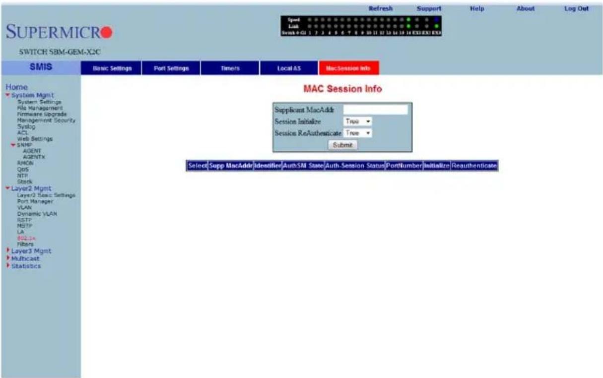
Clicking the MAC SESSION INFO tab brings up the MAC SESSION INFO page (Figure 7-21), which configures the supplicant MAC address. The parameters for this page are shown in Table 7-13.
Table 7-67. MAC Session Info Page Parameters
| Parameter Description | |
| Session Initialize | This parameter is the initialization control for this Supplicant MAC address. Setting this attribute to True causes the Supplicant session with this MAC address, to be initialized. The attribute value reverts to False once initialization has completed. |
| Session ReAuthenticate | This parameter is the reauthentication control for this Supplicant MAC address. Setting this attribute to True causes the Authenticator PAE state machine for this MAC address to reauthenticate the Supplicant. Setting this attribute to False has no effect. This attribute always returns to False when it is read. |
Filters
The Filters link allows you to configure Layer 2 packet filtering.
The Layer 2 packet filtering management has the following configuration pages:
• "Unicast Filters" on page 7-106
• "Multicast Filters" on page 7-107
Unicast Filters
Figure 7-92. L2 Unicast Filter Configuration Page
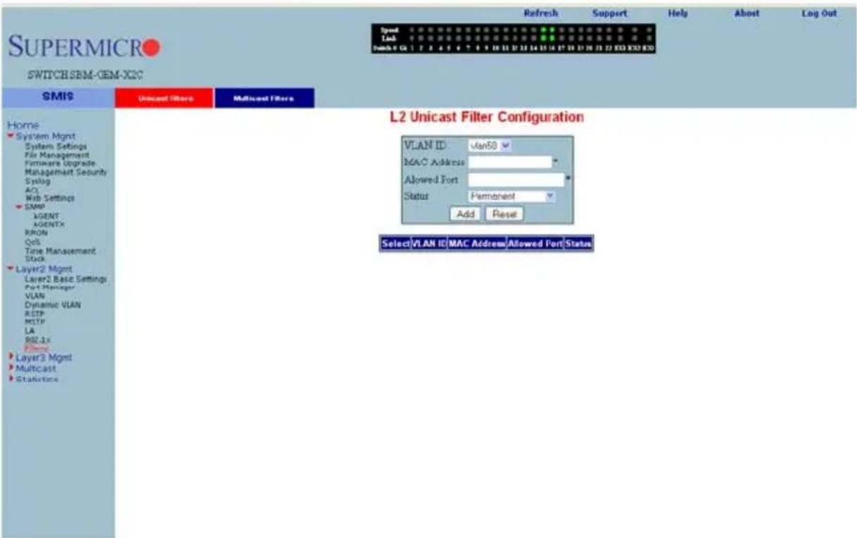
Clicking the UNICAST FILTERS tab brings up the L2 UNICAST FILTER CONFIGURATION page (Figure 7-21), which sets the filter configuration to control the unicast packets that the switch needs to process. The parameters for this page are shown in Table 7-13.
Table 7-68. L2 Unicast Filter Configuration Page Parameters
| Parameter Description | |
| FDB ID This parameter specifies the forwarding database ID. | |
| MAC Address | This parameter specifies the destination MAC address of the received packet. |
| Receive Port This parameter | specifies the port on which the packet was received. |
| Parameter Description Allowed Ports | This parameter specifies the list of ports on which the received packet, with the above set MAC address (if received from the configured port) can be forwarded. |
| Status | You can choose to set this configuration to any one of the following types:Other– For entries currently in use, but whose conditions remain different from the following values.Permanent– Entries that reside even after the restart of the switch.DeleteOnReset– This deletes the entry on restart.DeleteOnTimeout– This deletes the entry on expiration of the ageing timer. |
Multicast Filters
Figure 7-93. L2 Multicast Filter Configuration Page
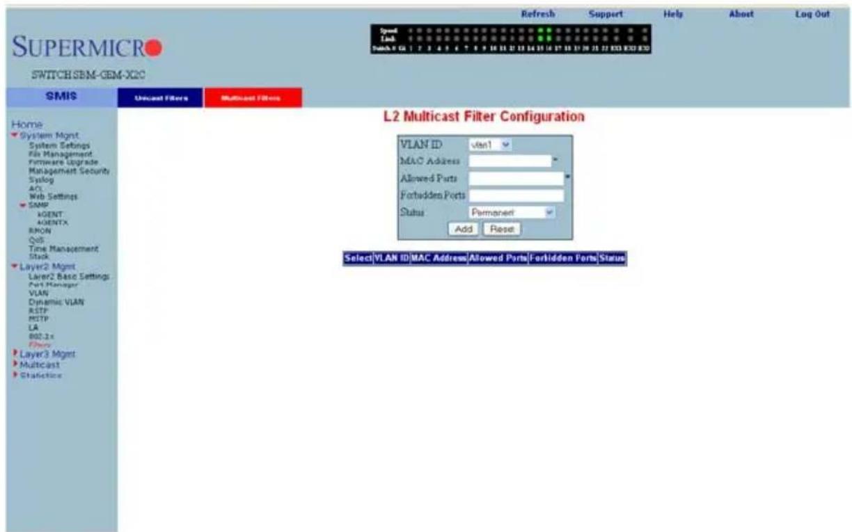
Clicking the MULTICAST FILTERS tab brings up the L2 MULTICAST FILTER CONFIGURATION page (Figure 7-21), which allows you to set the filter configuration to control the multicast packets that the switch needs to process. The parameters for this page are shown in Table 7-13.
Table 7-69. L2 Multicast Filter Configuration Page Parameters
| Parameter Description | |
| VLAN ID This parameter specifies the VLAN ID. | |
| MAC Address | This parameter specifies the destination MAC address of the received packet. |
| Receive Port This parameter | specifies the port on which the packet was received. |
| Allowed Ports | This parameter specifies the list of ports on which the received packet, with the above set MAC address (if received from the configured port) can be forwarded. |
| Forbidden Ports | This parameter specifies the list of ports on which the received packet, with the above set MAC address (if received from the configured port) must NOT be forwarded. |
| Status | You can choose to set this configuration to any one of the following types:Permanent– This configuration resides even after restart of the switch.DeleteOnReset– This configuration deletes the entry on restart.DeleteOnTimeout– This configuration deletes the entry on expiration of the ageing timer. |
7-6 Layer 3 Management
Figure 7-94. Layer3 Management Page
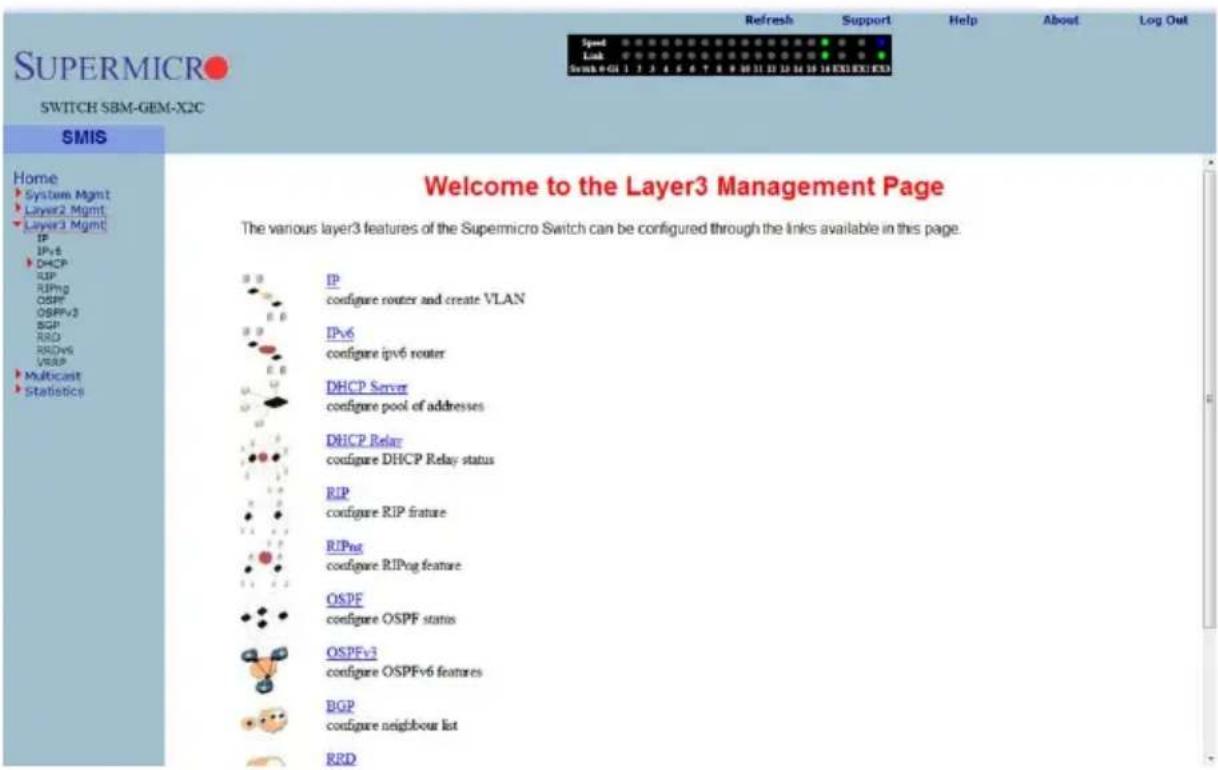
The LAYER 3 MANAGEMENT home page (Figure 7-94) has links to all Layer 3 features.
IP
The IP link enables you to perform IP related configuration. This can be done through the following pages.
• "Vlan Interface" on page 7-109
• "IP V4 Interface Settings" on page 7-110
• "IP Route" on page 7-111
- "LoopBack Basic Settings" on page 7-112
Vlan Interface
Figure 7-95. VLAN Interface Basic Settings Page
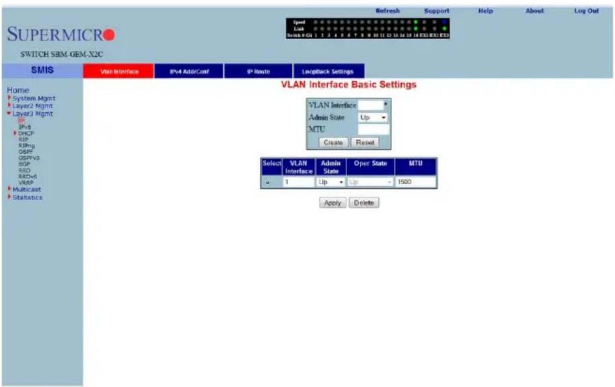
Clicking the VLAN INTERFACE tab brings up the VLAN INTERFACE BASIC SETTINGS page (Figure 7-95), which allows configuring of L3 VLAN interfaces. The parameters for this page are shown in Table 7-70.
Table 7-70. VLAN Interface Basic Settings Page Parameters
| Parameter Description | |
| VLAN Interface This parameter specifies the VLAN identifier. | |
| Admin State | This parameter specifies the admin state as either Up or Down. |
| MTU This parameter specifies the maximum transfer unit size in bytes. | |
IP V4 Interface Settings
Figure 7-96. IPv4 Interface Settings Page
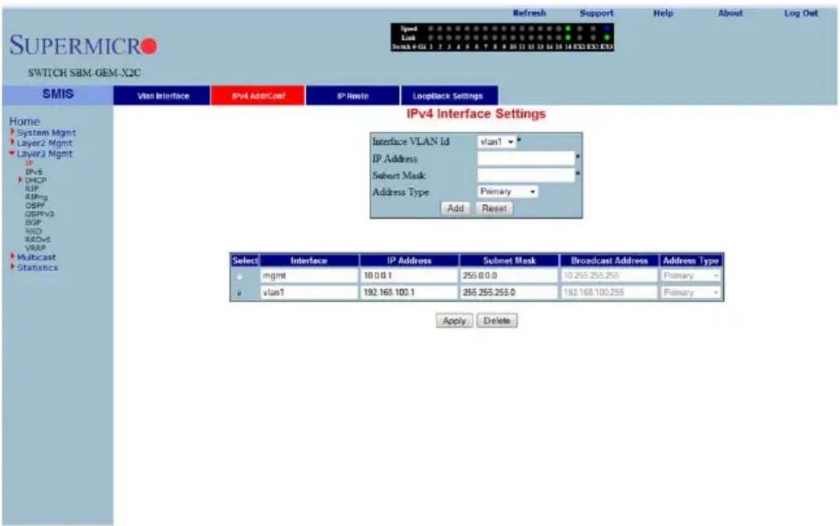
Clicking the IPv4 ADDR CONF tab brings up the IPv4 INTERFACE SETTINGS page (Figure 7-96), which allows you to configure the IP address for L3 VLANs. The parameters for this page are shown in Table 7-71.
Table 7-71. IPv4 Interface Settings Page Parameters
| Parameter Description | |
| Interface VLAN ID This parameter specifies the VLAN interface. | |
| IP Address | This parameter specifies the IP Address of the specified interface. |
| Subnet Mask This parameter indicates the mask for the specified IP Address. | |
| Address Type | This parameter specifies the type of address, which can be Primary or Secondary. |
IP Route
Figure 7-97. IP Route Configuration Page
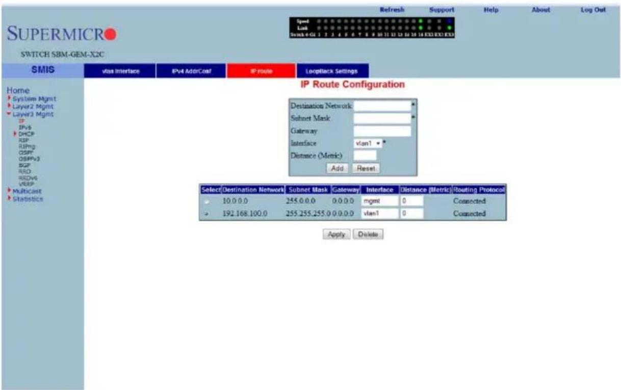
Clicking the IP ROUTE tab brings up the IP ROUTE CONFIGURATION page (Figure 7-97), which allows you to configure the static IP routes. The parameters for this page are shown in Table 7-72.
Table 7-72. IP Route Configuration Page Parameters
| Parameter Description | |
| Destination Network | This parameter specifies the network address for which the route is being added. |
| Subnet Mask | This parameter indicates the subnet mask for the Destination Network address. |
| Gateway This parameter denotes the Next Hop Gateway to reach the IP address. | |
| Interface This parameter specifies the outgoing interface. | |
| Distance (Metric) This parameter specifies the metric value of the destination. | |
LoopBack Basic Settings
Figure 7-98. LoopBack Basic Settings Page

Clicking the LOOPBACK SETTINGS tab brings up the LOOPBACK BASIC SETTINGS page (Figure 7-98), which allows you to configure loopback IP interfaces. The parameters for this page are shown in Table 7-73.
Table 7-73. LoopBack Basic Settings Page Parameters
| Parameter Description | |
| LoopBack Interface This parameter is the name of the loopback interface getting created. | |
| Interface Type This parameter is always the loopback for this configuration. | |
| Interface Status This parameter for the I NTERFACE STATUS can be set to Up or Down. | |
| IP Address This parameter specifies the IP address for this loopback interface. | |
| Subnet Mask This parameter specifies the subnet mask for this loopback interface. | |
IP V6
The IPv6 link allows you to perform IPv6 related configurations. This can be accomplished through the following six pages.
- "IPv6 Route Configuration" on page 7-113
- "IPv6 Interface" on page 7-114
- "ND Cache" on page 7-115
- "Address Settings" on page 7-116
- "Address Profile" on page 7-117
- "Prefix Settings" on page 7-118
IPv6 Route Configuration
Figure 7-99. IP6 Route Configuration Page
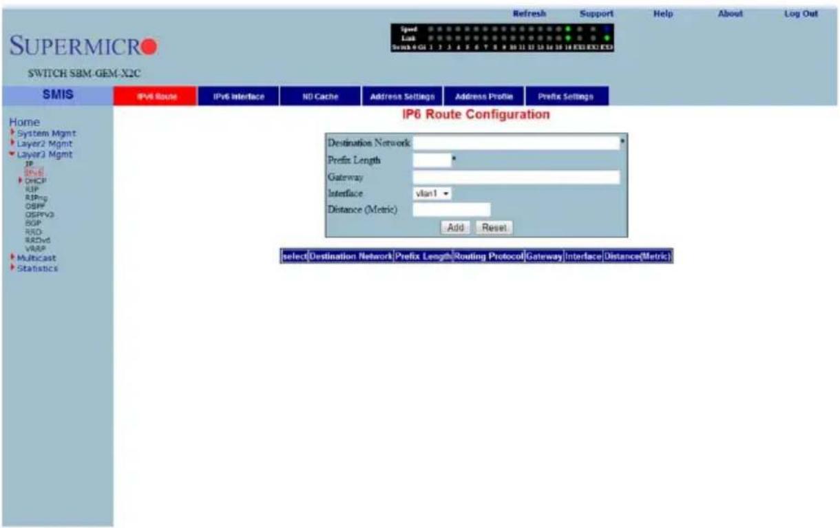
Clicking the IPv6 ROUTE tab brings up the IP6 ROUTE CONFIGURATION page (Figure 7-99), which configures various IP6 Route parameters. The parameters for this page are shown in Table 7-74.
Table 7-74. IP6 Route Configuration Page Parameters
| Parameter Description | |
| Destination Network | This parameter specifies the network address for which the IPv6 route is being added. |
| Prefix Length This parameter | specifies the subnet mask for the above said address. |
| Routing Protocol | This parameter indicates the routing protocol through which the route was learnt, if not manual. This cannot be configured. |
| Gateway This parameter specifies the Next Hop Gateway to reach the IP address. | |
| Interface This parameter indicates the outgoing interface. | |
| Distance (Metric) This parameter denotes metric value of the destination. | |
IPv6 Interface
Figure 7-100. IPv6 Interface Settings Page
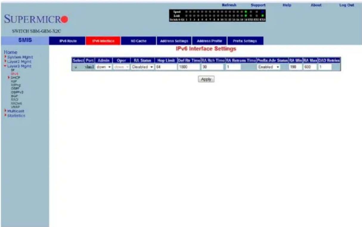
Clicking the IPv6 INTERFACE tab brings up the IPv6 INTERFACE SETTINGS page (Figure 7-100), which displays the various parameters for the IPv6 Interface. The parameters for this page are shown in Table 7-75.
Table 7-75. IPv6 Interface Settings Page Parameters
| Parameter Description | |
| Port This parameter specifies the Index of the VLAN interface. | |
| Admin This parameter indicates the Administrative Status of IPv6 on the Interface. | |
| Oper | This parameter specifies the Operational Status of IPv6 on the given Interface, which is a read-only field. |
| RA Status This parameter indicates the Router Advertisement status on the Interface. | |
| Hop Limit | This parameter denotes the Hop Limit value to be placed in the Router Advertisements sent on the Interface. |
| Def-Rtr Time | This parameter specifies the Default router lifetime to be placed in the Router Advertisements sent on the interface. |
| RA Rch Time | This parameter indicates the Reachable time to be placed in the Router Advertisements sent on the interface. |
| RA Retrans Time | This parameter specifies the RA Retransmit time to be placed in the Router Advertisement sent on the interface. |
| Prefix-Adv Status | This parameter specifies the Prefix Advertisement status on the Interface. |
| RA Min | This parameter specifies the minimum time in seconds allowed between sending unsolicited router advertisements. |
| RA Max | This parameter indicates the maximum time in seconds allowed between sending unsolicited router advertisements. |
| DAD Retries | This parameter specifies the maximum number of Duplicate Address Detection retries. |
ND Cache
Figure 7-101. ND Cache Configuration Page
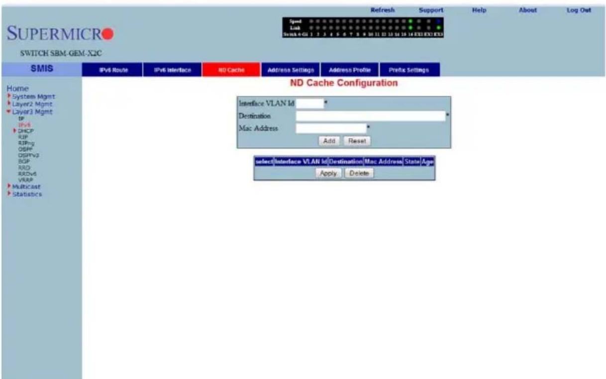
Clicking the ND CACHE tab brings up the ND CACHE CONFIGURATION page (Figure 7-101). The parameters for this page are shown in Table 7-76.
Table 7-76. ND Cache Configuration Page Parameters
| Parameter Description | |
| Interface VLAN ID This parameter indicates index of the VLAN interface. | |
| Destination This parameter specifies Destination IPv6 address. | |
| MAC Address This parameter denotes the physical address of the Destination address. | |
| State | This parameter indicates the Reachability state of the entry, which is a read-only field. |
| Age This parameter specifies the Age Time. | |
Address Settings
Figure 7-102. Address Settings Page
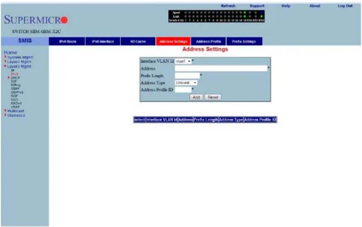
Clicking the ADDRESS SETTINGS tab brings up the ADDRESS SETTINGS page (Figure 7-102), which allows you to configure address settings for IPv6. The parameters for this page are shown in Table 7-77.
Table 7-77. Address Settings Page Parameters
| Parameter Description | |
| Interface VLAN ID This parameter specifies the index of the VLAN Interface. | |
| Address This parameter specifies the IPv6 address. | |
| Prefix Length | This parameter indicates the length of the prefix (in bits) associated with this entry's IPv6 address. |
| Address Type | This parameter specifies that the type of address can be Link-Local, Global-Unicast or Anycast. |
| Address Profile ID This parameter indicates the index to the IPv6 address Profile table. | |
Address Profile
Figure 7-103. Address Profile Settings Page
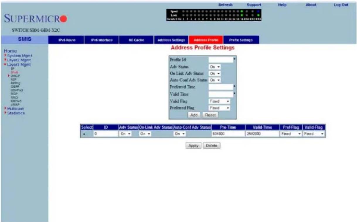
Clicking the ADDRESS PROFILE tab brings up the ADDRESS PROFILE SETTINGS page (Figure 7-103). The parameters for this page are shown in Table 7-78.
Table 7-78. Address Profile Settings Page Parameters
| Parameter Description | |
| Profile ID This parameter specifies the index of the Address Profile entry. | |
| Adv Status This parameter specifies the Prefix Advertise status. | |
| On Link Adv Status This parameter indicates the On-Link Advertise Flag status. | |
| Auto Conf Adv Status | This parameter denotes the Autonomous Configuration Advertise Flag status. |
| Preferred Time | This parameter specifies the Preferred Lifetime of the prefix address that uses this profile. |
| Valid Time | This parameter indicates the Valid Lifetime of the prefix address that uses this profile. |
| Valid Flag | This parameter specifies if the Valid Lifetime Flag is Variable or Fixed. |
| Preferred Flag | This parameter specifies if the Preferred Lifetime Flag is Variable or Fixed. |
Prefix Settings
Figure 7-104. Prefix Configuration Page
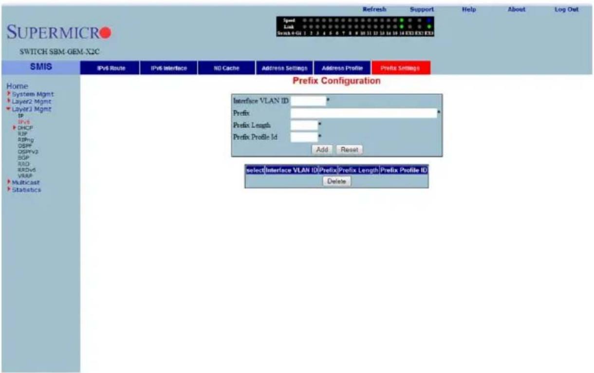
Clicking the PREFIX SETTINGS tab brings up the PREFIX CONFIGURATION page (Figure 7-104). The parameters for this page are shown in Table 7-79.
Table 7-79. Prefix Configuration Page Parameters
| Parameter Description | |
| Interface VLAN ID This parameter specifies the index of the VLAN Interface. | |
| Prefix This parameter indicates the IPv6 address prefix to be advertised in RA. | |
| Prefix Length This parameter indicates the P | REFIX LENGTH (in bits). |
| Prefix Profile ID This parameter specifies index to the IPv6 address profile table. | |
DHCP Server
The DHCP Server link helps you to manage the DHCP server in the switch through the following two pages:
• "DHCP Basic Settings" on page 7-119
• "Pool Settings" on page 7-120
DHCP Basic Settings
Figure 7-105. DHCP Basic Settings Page
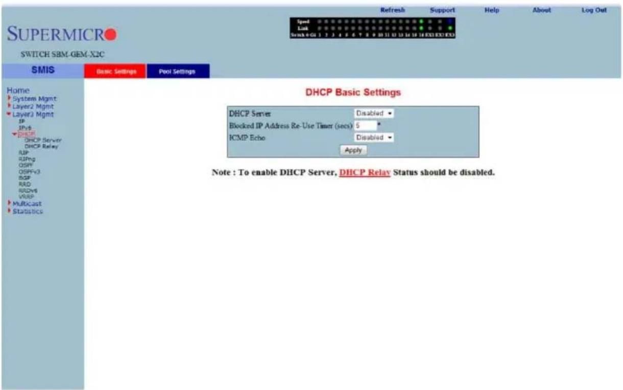
Clicking the DHCP SETTINGS tab brings up the DHCP BASIC SETTINGS page (Figure 7-105). The parameters for this page are shown in Table 7-80.
Table 7-80. DHCP Basic Settings Page Parameters
| Parameter Description | |
| DHCP-Server | With this parameter you can enable or disable the DHCP server using this configuration. |
| Offer-reuse Time out (seconds) | This parameter specifies the Reuse Timeout value that can be configured in this field, which is used by DHCP. |
| ICMP Echo This parameter enables or disables the ICMP Echo feature. | |
Pool Settings
Figure 7-106. DHCP Pool Settings Page
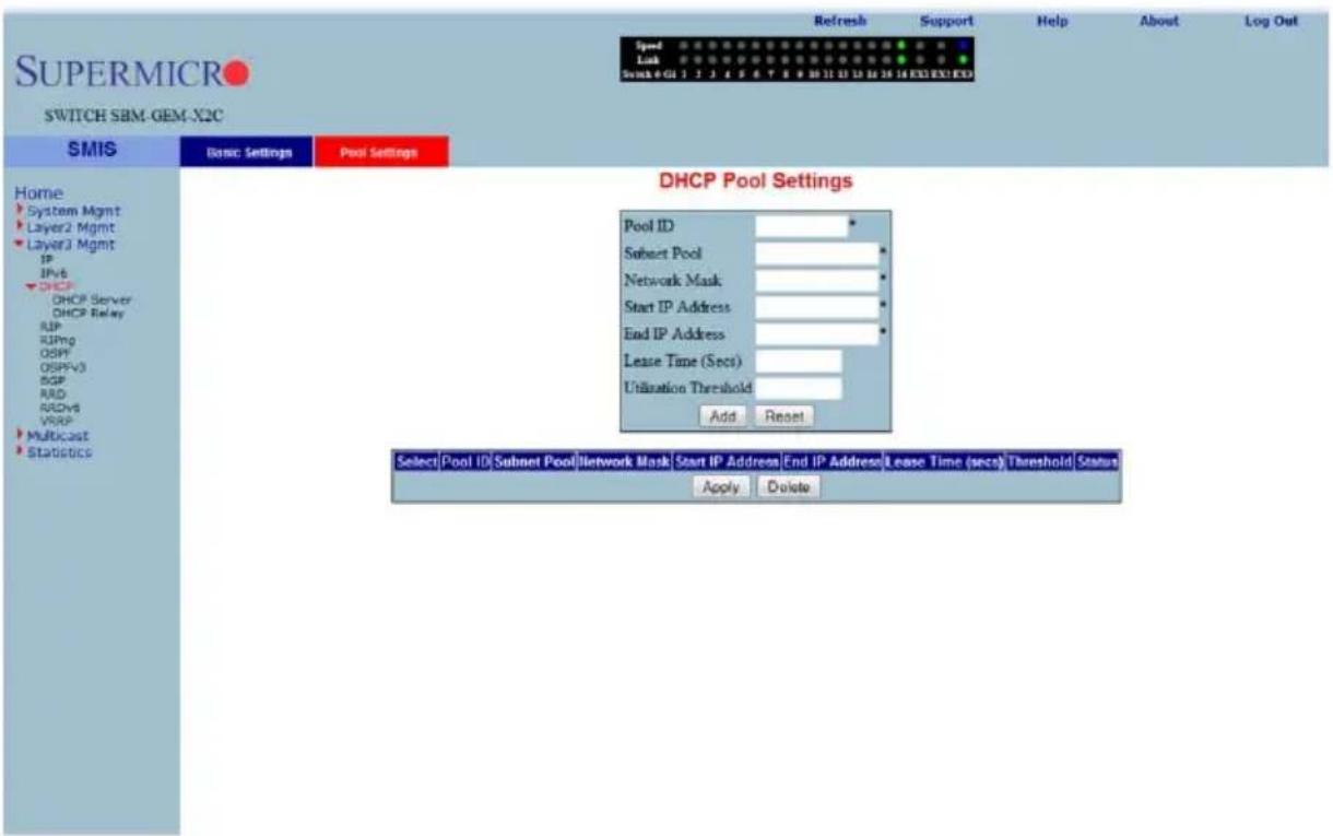
Clicking the POOL SETTINS link brings up the DHCP POOL SETTINGS page (Figure 7-106), which allows you to configure the IP address pool that can be used by the DHCP server to allocate IP addresses. The parameters for this page are shown in Table 7-81.
Table 7-81. DHCP Pool Settings Page Parameters
| Parameter Description | |
| Pool ID | This parameter specifies the pool ID to index among the different subnet pools configured. |
| Network This parameter specifies the subnet of the IP address in the pool. | |
| Subnet Mask This parameter specifies the subnet mask of the IP address in the pool. | |
| Start IP | This parameter specifies the first IP address in the address pool that is used for dynamic allocation by the DHCP server. |
| End IP | This parameter specifies the last IP address in the address pool that is used for dynamic allocation by the DHCP server. |
| Lease Time | This parameter specifies the time interval for which the IP address is valid. |
| Utilization Threshold This parameter specifies the DHCP Pool Utilization Threshold value. | |
| Status This parameter specifies the status of the entry. | |
DHCP Relay
The DHCP Relay link helps you to manage the DHCP relay in the switch through the following two pages:
- "DHCP Relay Basic Settings" on page 7-121
- "Interface Settings" on page 7-122
DHCP Relay Basic Settings
Figure 7-107. DHCP Relay Configuration Page
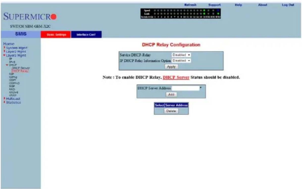
Clicking the BASIC SETTINGS tab brings up the DHCP RELAY CONFIGURATION page (Figure 7-107), which displays the various parameters for configuring the DHCP relay. The parameters for this page are shown in Table 7-82.
Table 7-82. DHCP Relay Configuration Page Parameters
| Parameter Description | |
| Service DHCP-Relay | This parameter specifies the DHCP relay status that can be enabled or disabled in the switch using this field. |
| IP DHCP Relay Information Option | You can enable/disable this field to control the processing related to the Relay Agent Information options. |
| DHCP Server Address | This parameter indicates the IP address of the DHCP Server to which the Relay Agent needs to forward the packets from the client. |
Interface Settings
Figure 7-108. DHCP Relay Interface Configuration Page
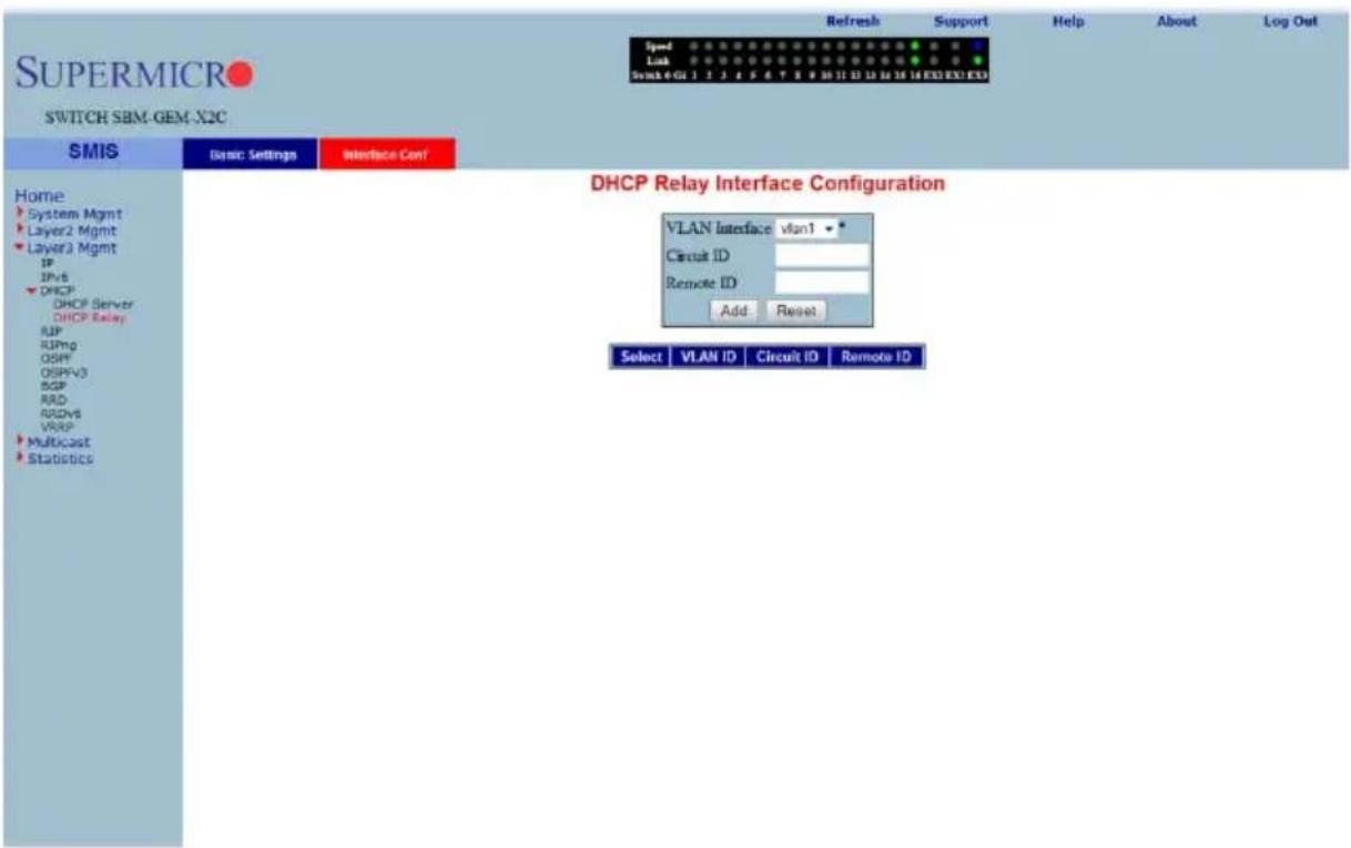
Clicking the INTERFACE CONF tab brings up the DHCP RELAY INTERFACE CONFIGURATION page (Figure 7-108), which allows you to configure the DHCP relay for VLANs. The parameters for this page are shown in Table 7-83.
Table 7-83. DHCP Relay Interface Configuration Page Parameters
| Parameter Description | |
| VLAN Interface This parameter specifies the VLAN Interface name. | |
| Circuit ID This parameter specifies the DHCP Relay Circuit identifier. | |
| Remote ID This parameter specifies the Remote identifier. | |
RIP
The RIP link opens the following links for configuration of RIP protocol:
• "RIP Basic Settings" on page 7-123
- "Interfaces" on page 7-124
• "Neighbors List" on page 7-125
• "Security Settings" on page 7-126
- "Address Summarization" on page 7-127
RIP Basic Settings
Figure 7-109. RIP Basic Settings Page
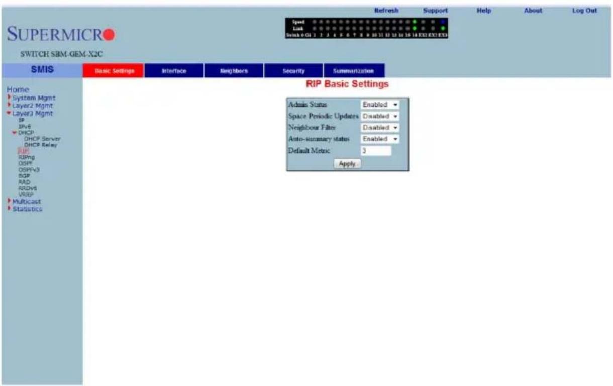
Clicking the BASIC SETTINGS tab brings up the RIP BASIC SETTINGS page (Figure 7-109). The parameters for this page are shown in Table 7-84.
Table 7-84. RIP Basic Settings Page Parameters
| Parameter Description | |
| Output-delay | This parameter specifies the delay that needs to be enabled for RIP to split the periodic update packets before they are sent out. |
| Neighbor Filter | This parameter enables or disables neighbor filtering. Neighbor filtering helps you to filter routes from specific neighbors. |
| Auto-summary status This parameter enables or disables the Auto-summary feature. | |
Interfaces
Figure 7-110. RIP Interface Page
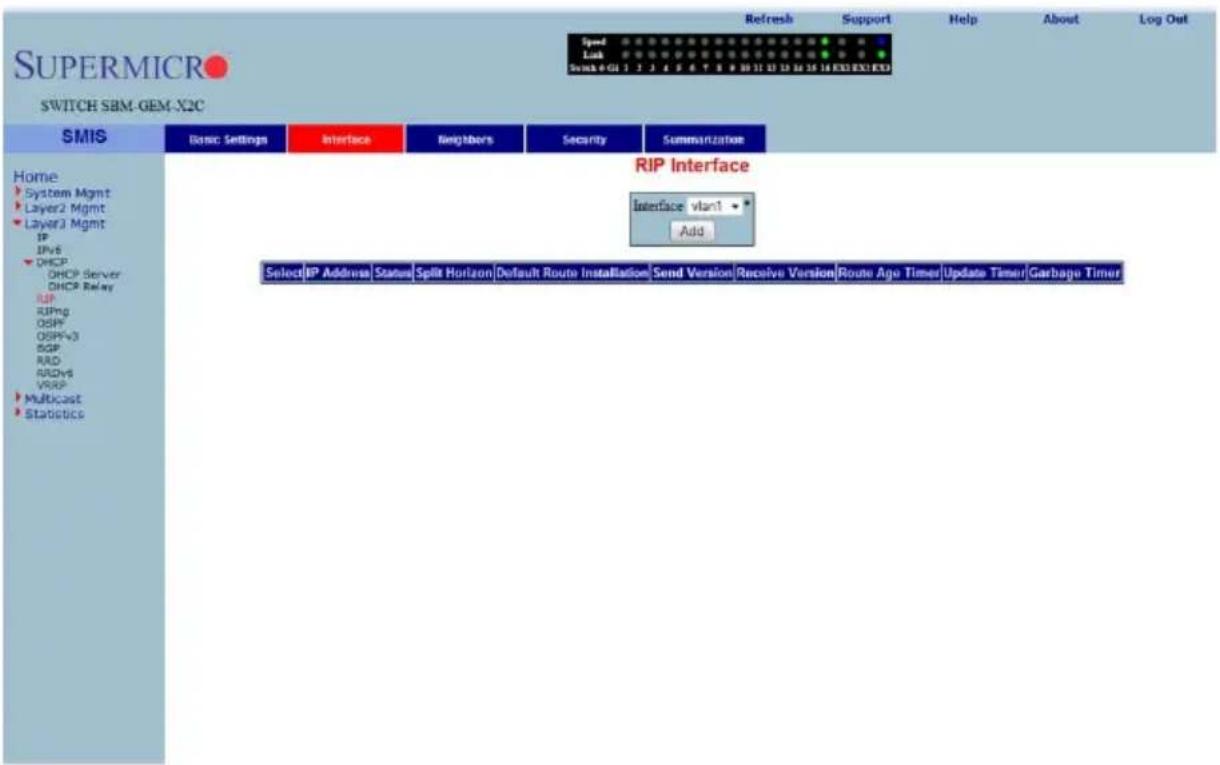
Clicking the INTERFACE tab brings up the RIP INTERFACE page (Figure 7-110). The parameters for this page are shown in Table 7-85.
Table 7-85. RIP Interface Page Parameters
| Parameter Description | |
| Interface | This parameter specifies the Interface ID for which RIP needs to be configured. |
| IP Address This parameter specifies the IP address of the RIP interface. | |
| Status This parameter specifies the admin status of the interface. | |
| Split Horizon | This parameter specifies the operational status of Split Horizon in the system. |
| Default Route Installation | This parameter specifies whether Default Route Installation can be done or not. |
| Send Version | This parameter allows selecting the RIP packets sent to be compatible to either RIPv1 , RIPv1 Compatible or RIPv2 . |
| Receive Version | This parameter is similar to SEND VERSION, but it allows you to choose the RIP packets to be received as either RIPv1 , RIPv2 , both RIPv1 and RIPv2 or None. |
| Route Age Timer | This parameter specifies the time interval after which the routes will be flushed. |
| Update Timer | This parameter specifies the time interval between successive RIP updates. |
| Garbage Timer | This parameter specifies the time interval after which the invalid routes will be removed from the routing table. |
Neighbors List
Figure 7-111. RIP Neighbor List Page
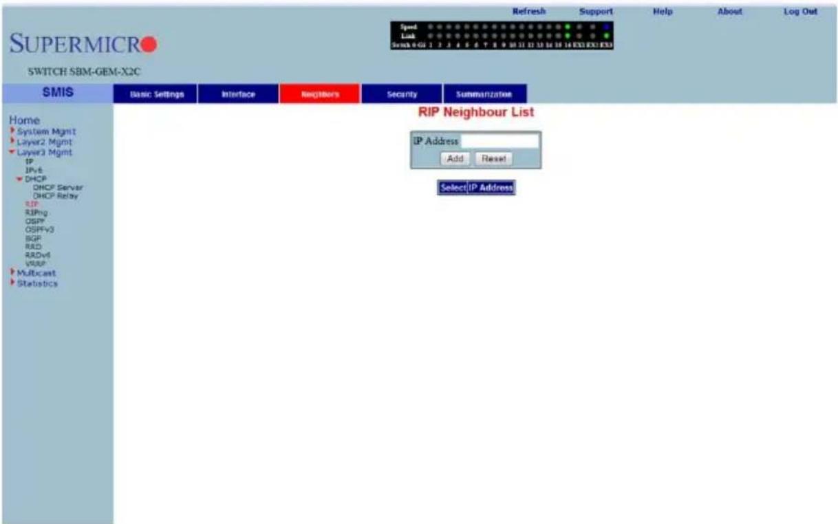
Clicking the NEIGHBORS tab brings up the RIP NEIGHBOR LIST page (Figure 7-111), which is used to configure the RIP neighbors, by configuring their IP address.
The single parameter for this page is IP ADDRESS, which specifies the IP Address of the neighbor router to which the unicast update has to be sent.
Security Settings
Figure 7-112. RIP Security Settings Page
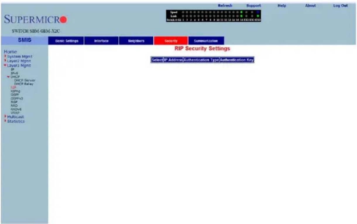
Clicking the SECURITY tab brings up the RIP SECURITY SETTING page (Figure 7-112). The parameters for this page are shown in Table 7-13.
Table 7-86. RIP Security Setting Page Parameters
| Parameter Description | |
| IP Address | This parameter displays the active RIP interfaces. You can select the interface for which you want to configure authentication. |
| Authentication Type | This parameter specifies the authentication type. You can choose No Authentication, or Simple Password, or the md5 authentication type. |
| Authentication Key | This parameter specifies the key used for authentication if the authentication type is other than No Authentication. |
Address Summarization
Figure 7-113. RIP Interface Specific Address Summarization Page
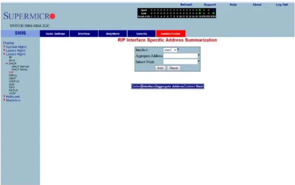
Clicking the SUMMARIZATION tab brings up the RIP INTERFACE SPECIFIC ADDRESS SUMMARIZATION page (Figure 7-113). The parameters for this page are shown in Table 7-87.
Table 7-87. RIP Interface Specific Address Summarization Page Parameters
| Parameter Description | |
| Interface | This parameter specifies the Interface ID for which the RIP aggregate address needs to be configured. |
| Aggregate Address This parameter specifies the aggregate address. | |
| Subnet Mask This parameter specifies the mask of the aggregate address. | |
RIPng
The RIP6 link allows you perform RIPv6 related configuration for the switch. This can be accomplished through the following two pages:
- "RIP6 Interface" on page 7-128
- "Filters" on page 7-129
RIP6 Interface
Figure 7-114. RIP6 Interface Configuration Page
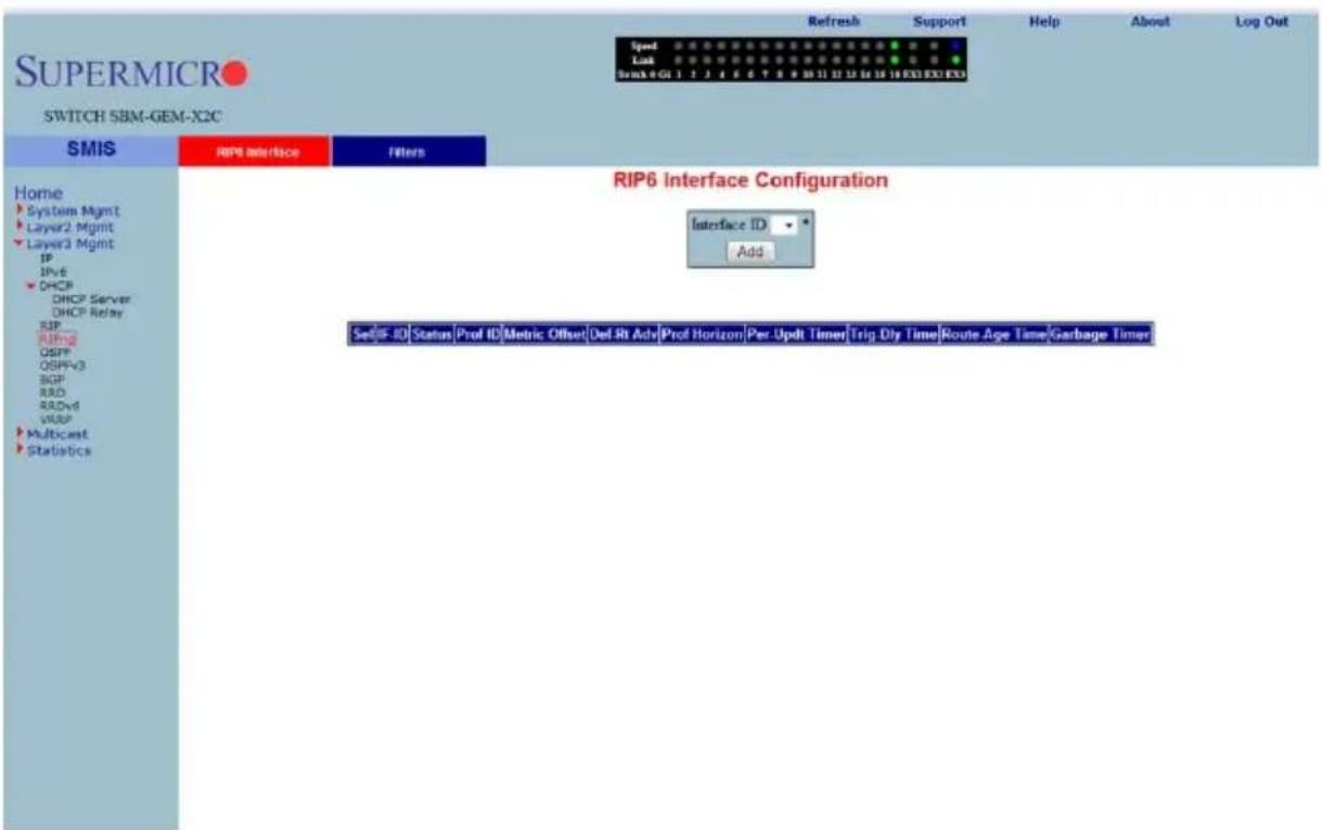
Clicking the RIP6 INTERFACE tab brings up the RIP6 INTERFACE CONFIGURATION page (Figure 7-114). The parameters for this page are shown in Table 7-88.
Table 7-88. RIP6 Interface Configuration Page Parameters
| Parameter Description | |
| Interface ID Specifies the Interface Id for which RIPv6 needs to be configured. | |
| Status This parameter specifies the administration status of the interface. | |
| Prof ID This parameter indicates the Index of the Address Profile entry. | |
| Metric Offset | This parameter specifies the metric for the routes that are being re-distributed. |
| Def Rt Adv | This parameter indicates the default router lifetime to be placed in the Router Advertisements sent on the interface. |
| Parameter DescriptionProf Horizon | This parameter specifies the operational status of Profile Horizon in the system. |
| Per-Updt Timer | This parameter specifies the time interval between successive RIP6 updates. |
| Trig-Dly Time | This parameter indicates the time interval in seconds by which further triggered updates are delayed, after one triggered update is sent. |
| Route Age Time | This parameter specifies the time interval after which, the routes are flushed. |
| Garbage Timer | This parameter specifies the time interval after which, the invalid routes are removed from the routing table. |
Filters
Figure 7-115. RIP6 Filter Configuration Page
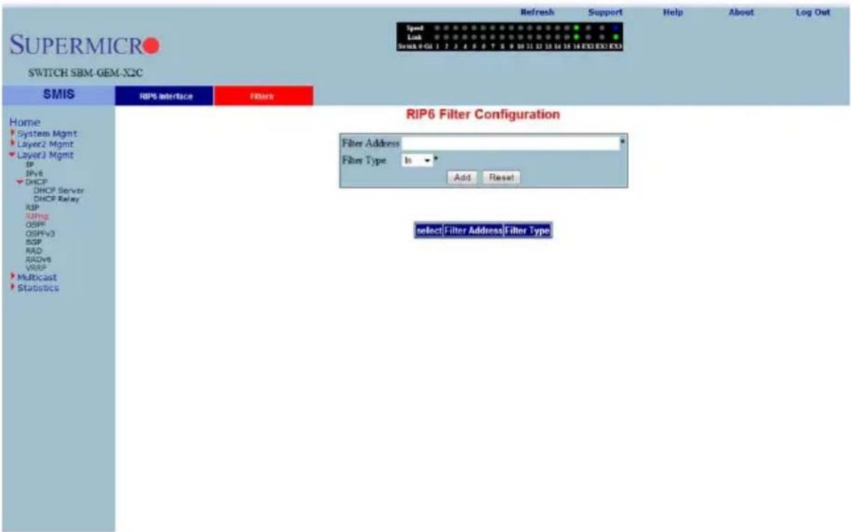
Clicking the FILTERS tab brings up the RIP6 FILTER CONFIGURATION page (Figure 7-115). The parameters for this page are shown in Table 7-89.
Table 7-89. RIP6 Filter Configuration Page Parameters
| Parameter Description | |
| Filter Address | This parameter specifies the FILTER ADDRESS for the RIP6 interface. |
| Filter Type | This parameter specifies the FILTER TYPE for which RIP6 needs to be configured. |
OSPF
The OSPF link allows you to configure the OSPF protocol through the following pages:
- "OSPF Basic Settings" on page 7-131
- "Area" on page 7-132
- "Interface" on page 7-133
• "Virtual Interface" on page 7-134
• "OSPF Neighbor" on page 7-135 - "OSPF RRD Route Configuration" on page 7-136
• "OSPF Area Aggregation" on page 7-137
• "External Aggregation" on page 7-138
OSPF Basic Settings
Figure 7-116. OSPF Basic Settings Page
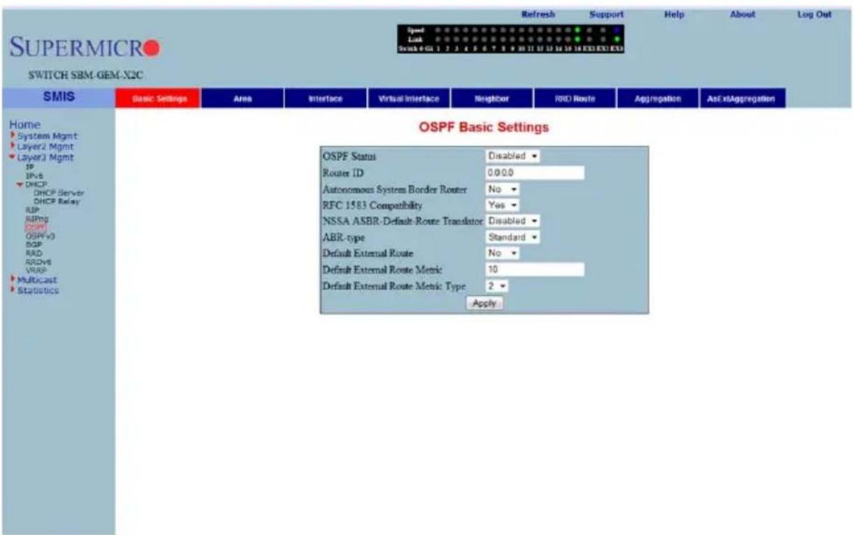
Clicking the BASIC SETTINGS tab brings up the OSPF BASIC SETTINGS page (Figure 7-116). The parameters for this page are shown in Table 7-90.
Table 7-90. OSPF Basic Settings Page Parameters
| Parameter Description | |
| OSPF Status This parameter specifies the global status of the protocol in the switch. | |
| Router ID This parameter specifies the router identifier. | |
| Autonomous System Border Router | This parameter indicates the flag to denote whether or not the router is to be configured as an Autonomous System Border Router. |
| RFC 1583 Compatibility | This parameter specifies the compatibility to RFC 1583 for choosing the route among multiple AS for the same destination. |
| External Link State Database Limit | This parameter specifies the maximum number of non-default AS-external-LSA entries that can be stored in the link state database. |
Area
Figure 7-117. OSPF Area Configuration Page
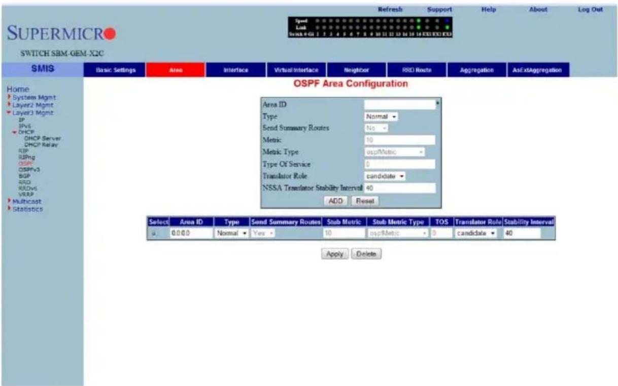
Clicking the AREA tab brings up the OSPF AREA CONFIGURATION page (Figure 7-117). The parameters for this page are shown in Table 7-91.
Table 7-91. OSPF Area Configuration Page Parameters
| Parameter Description | |
| Area ID This parameter specifies the identifier for the area. | |
| Type | This parameter allows you to configure the area type, as a Stub area, a Normal area or NSSA. |
| Send Summary Router | This field is used to control the import of summary LSAs to stub areas. This does not have any impact for other areas. |
| Default Cost | This parameter specifies the metric/cost associated with the routes. |
Interface
Figure 7-118. OSPF Interface Configuration Page
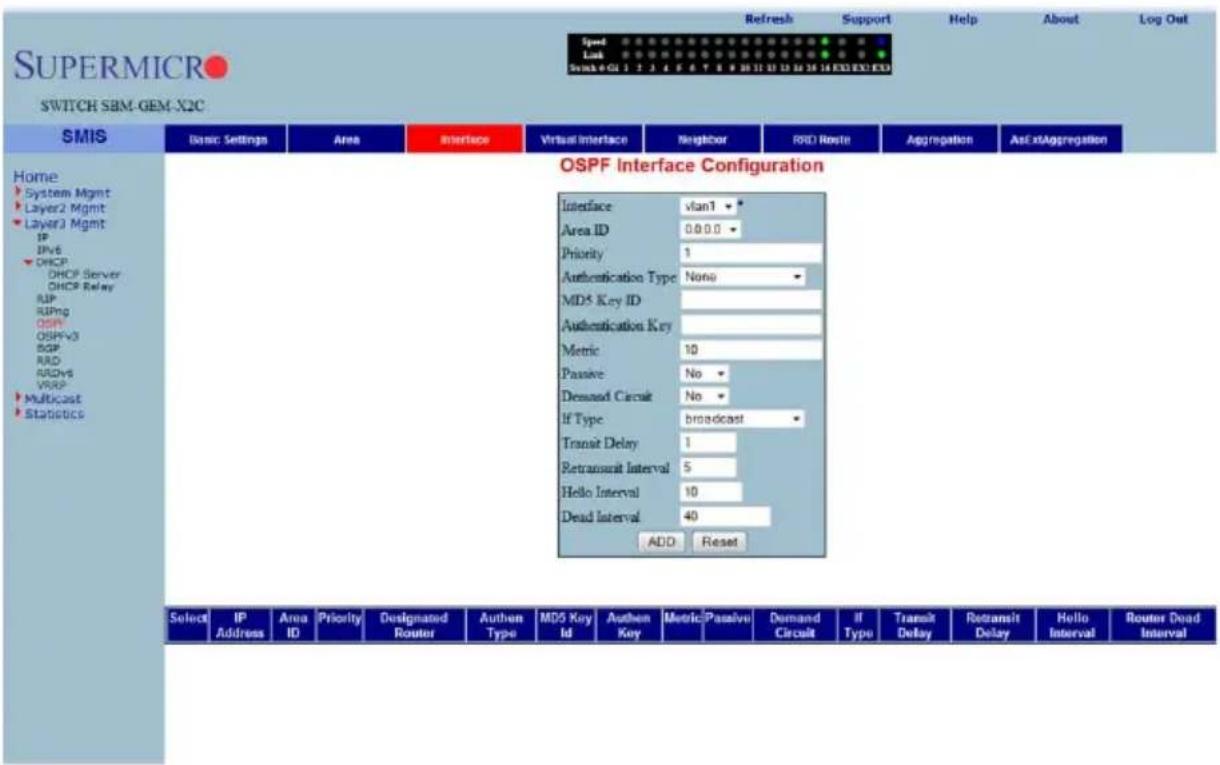
Clicking the INTERFACE tab brings up the OSPF INTERFACE CONFIGURATION page (Figure 7-118). The parameters for this page are shown in Table 7-92.
Table 7-92. OSPF Interface Configuration Page Parameters
| Parameter Description | |
| Interface This parameter specifies the interface index of the port. | |
| Area ID | This parameter indicates the 32-bit integer uniquely identifying the area to which the interface connects. |
| Priority | This parameter specifies the priority of this interface, which is used in the DR election algorithm. |
| Authentication Type | This parameter allows you to choose MD5, Simple Password or None as the authentication type. |
| MD5 Key ID | This parameter specifies the secret key used to create the message digest appended to the OSPF packet, if the authentication type is MD5. |
| Authentication Key | This parameter specifies the key required for authentication, if authentication is enabled on this interface. |
| IP Address This parameter specifies the IP Address of the OSPF interface. | |
| Parameter DescriptionDesignated Router This read-only field specifies the IP Address of the Designated Router. | |
| Status | When this parameter is enabled, the interface is advertised as an internal route to some area. When disabled it denotes that the interface is external to OSPF. |
Virtual Interface
Figure 7-119. OSPF Virtual Interface Configuration Page
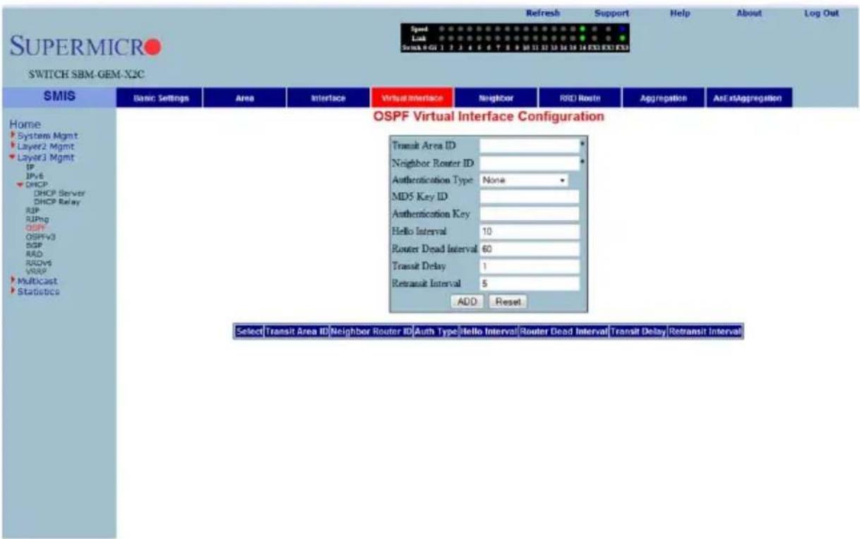
Clicking the VIRTUAL INTERFACE tab brings up the OSPF VIRTUAL INTERFACE CONFIGURATION page (Figure 7-119). The parameters for this page are shown in Table 7-93.
Table 7-93. OSPF Virtual Interface Configuration Page Parameters
| Parameter Description | |
| Transit Area ID This parameter specifies the transit area that the virtual link traverses. | |
| Neighbor Router ID This parameter specifies the router ID of the virtual neighbor. | |
| Authentication Type | This parameter allows you to choose MD5, Simple Password or None as the authentication type. |
| Parameter DescriptionMD5 Key ID | This parameter specifies the secret key used to create the message digest appended to the OSPF packet if the authentication type is MD5. |
| Authentication Key | This parameter specifies the key required for authentication, if authentication is enabled on this interface. |
OSPF Neighbor
Figure 7-120. OSPF Neighbor Configuration Page
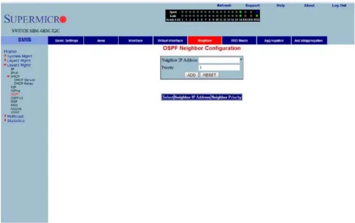
Clicking the NEIGHBOR tab brings up the OSPF NEIGHBOR CONFIGURATION page (Figure 7-120), which allows you to configure OSPF neighbors. The parameters for this page are shown in Table 7-94.
Table 7-94. OSPF Neighbor Configuration Page Parameters
| Parameter Description | |
| Neighbor IP Address This parameter specifies the neighbor router ID. | |
| Priority This parameter specifies a number value for the router priority. | |
OSPF RRD Route Configuration
Figure 7-121. OSPF RRD Route Configuration Page
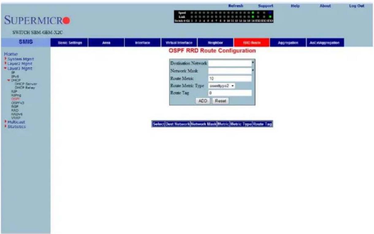
Clicking the RRD ROUTE tab brings up the OSPF RRD ROUTE CONFIGURATION page (Figure 7-121), which displays the various parameters for RRD Route configuration. The parameters for this page are shown in Table 7-95.
Table 7-95. OSPF RRD Route Configuration Page Parameters
| Parameter Description | |
| Destination Network | This parameter specifies the DESTINATION NETWORK. |
| Network Mask | This parameter specifies the NETWORK MASK. |
| Route Metric This parameter | specifies the R OUTE METRIC. |
| Route Metric Type | This parameter specifies the ROUTE METRIC TYPE. |
| Route Tag This parameter specifies the R OUTE TAG. | |
OSPF Area Aggregation
Figure 7-122. OSPF Area Aggregation Page
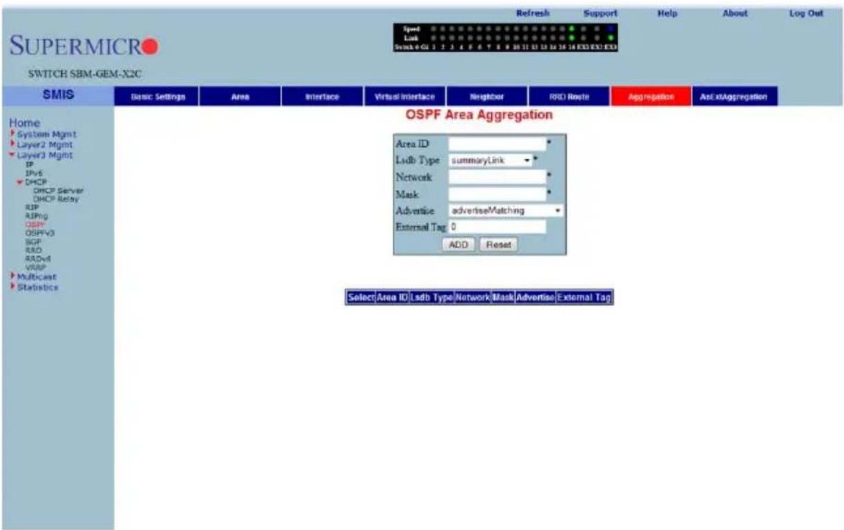
Clicking the AGGREGATION tab brings up the OSPF AREA AGGREGATION page (Figure 7-122). The parameters for this page are shown in Table 7-96.
Table 7-96. OSPF Area Aggregation Page Parameters
| Parameter Description | |
| Area ID | This parameter specifies the area associated with the OSPF address range. It is specified as an IP address. |
| Lsdb Type | This parameter specifies the link state data base type as a Summary Link or as a NSSA External Link. |
| Network This parameter specifies the network address. | |
| Mask This parameter specifies the network mask. | |
| Advertise | This parameter specifies the advertise option as Advertise Matching or Do Not Advertise Matching. |
| External Tag | This parameter is not used by the OSPF protocol itself. It may be used to communicate information between AS boundary routers. The precise nature of this information is outside the scope of OSPF. |
External Aggregation
Figure 7-123. OSPF As External Aggregation Configuration Page
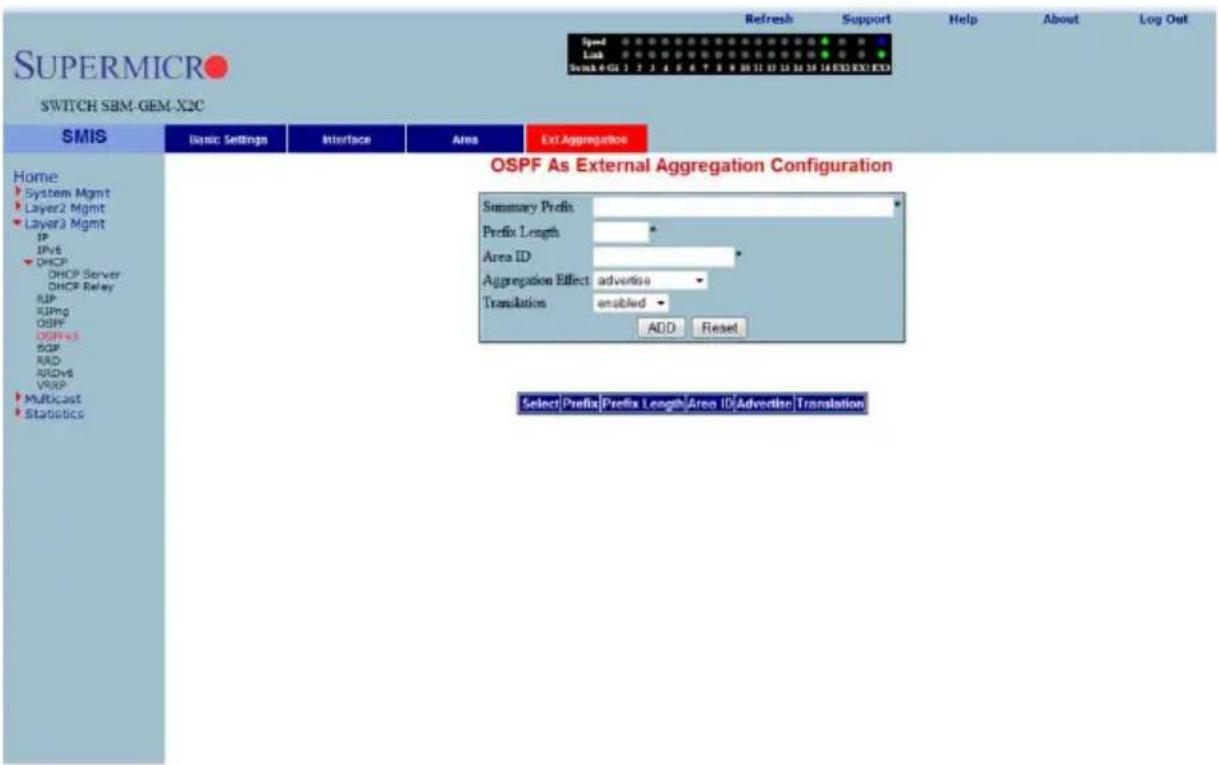
Clicking the EXT AGGREGATION tab brings up the OSPF AS EXTERNAL AGGREGATION CONFIGURATION page (Figure 7-123), which allows you to configure OSPF external aggregation parameters. The parameters for this page are shown in Table 7-97.
Table 7-97. OSPF As External Aggregation Configuration Page Parameters
| Parameter Description | |
| Network This parameter specifies the external network address. | |
| Mask This parameter specifies the network mask. | |
| Area ID This parameter specifies the Area identifier. | |
Table 7-97. OSPF As External Aggregation Configuration Page Parameters
| Parameter DescriptionAggregation Effect | This parameter specifies the Aggreation option as one of the following:Advertise – When set toadvertiseand associated Area ID is 0.0.0.0, then the aggregated Type-5 are generated. Otherwise if the associated Area ID is x.x.x.x (other than 0.0.0.0), then the aggregated Type-7 is generated in NSSA x.x.x.x for the specified range.Do Not Advertise – When set todoNotAdvertise(2) and associated Area ID is 0.0.0.0, then the Type-5 is not generated for the specified range, while aggregated Type-7 are generated in all attached NSSA. While if the associated Area ID is x.x.x.x (other than 0.0.0.0), then the Type-7 are not generated in NSSA x.x.x.x for the specified range.Allow All – When set toallowAlland associated Area ID is 0.0.0.0, then the aggregated Type-5 are generated for the specified range. In addition aggregated Type-7 are generated in all attached NSSA for the specified range.Deny All – When set todenyAllneither Type-5 nor Type-7 will be generated for the specified range. |
| Translation This parameter enables or disables the translation. | |
OSPF V3
The OSPFv3 link allows you to configure the OSPFv3 protocol through the following pages:
- "OSPFv3 Basic Settings" on page 7-140
- "Interface" on page 7-141
- "Area" on page 7-143
- "OSPF V3 External Aggregation" on page 7-144
OSPFv3 Basic Settings
Figure 7-124. OSPFv3 Basic Settings Page
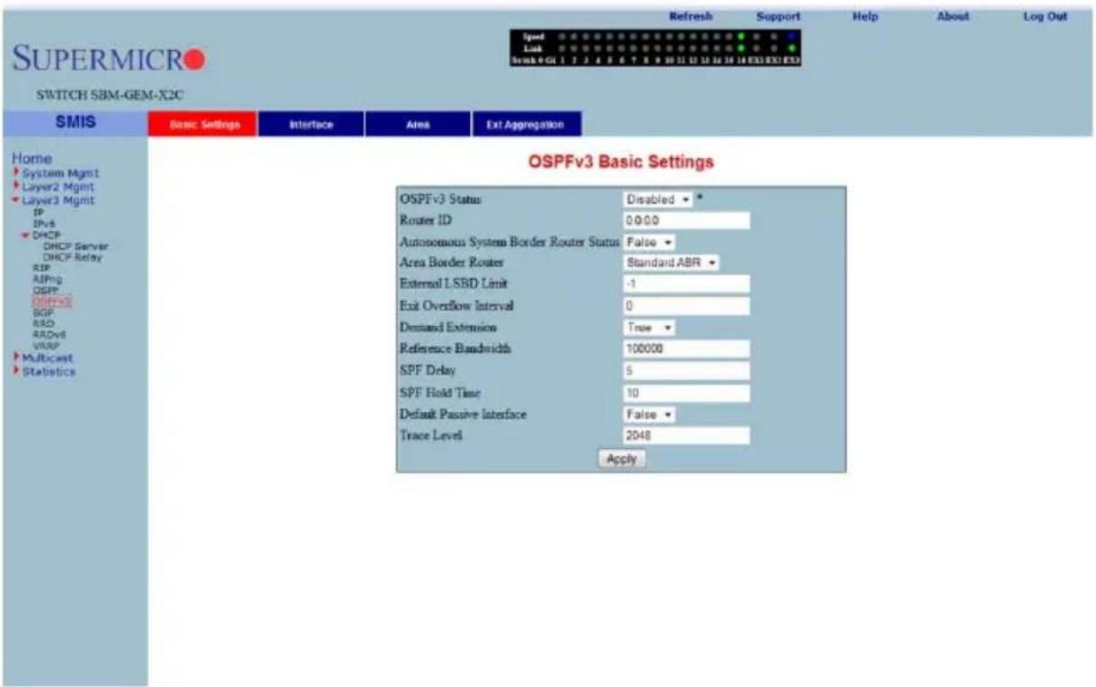
Clicking the BASIC SETTINGS tab brings up the OSPFv3 BASIC SETTINGS page (Figure 7-124). The parameters for this page are shown in Table 7-98.
Table 7-98. OSPFv3 Basic Settings Page Parameters
| Parameter Description | |
| OSPFv3 Status This parameter enables or disables OSPFv3 administratively. | |
| Router ID This parameter uniquely identifies the router in the Autonomous System. | |
| Autonomous System Border Router Status | This parameter specifies the router as Autonomous System border router. |
| Area Border Router This parameter specifies the router as an area border router. | |
| External LSDB Limit | This parameter specifies maximum number of non-default AS-external-LSAs entries that can be stored in the link-state database. |
| Exit Overflow Interval | This parameter specifies the time interval in seconds a router will attempt to leave OverflowState. |
| Demand Extension This parameter indicates the router's support for demand routing. | |
| Reference Bandwidth | This parameter specifies Reference bandwidth in kilobits/seconds, for calculating default interface metrics. |
| SPF Delay | This parameter indicates the delay in routing calculation after a topology change. |
| SPF Hold Time | This parameter specifies the minimum time between two consecutive SPF calculations. |
| Default Passive Interface | This parameter specifies whether all the OSPFv3 interfaces created after this setting are passive or not. |
| Trace Level This parameter defines the level of trace required for OSPFv3. | |
Interface
Figure 7-125. Interface Settings Page
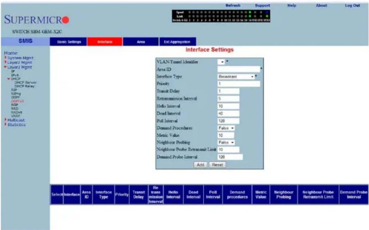
Clicking the INTERFACE tab brings up the INTERFACE SETTINGS page (Figure 7-125). The parameters for this page are shown in Table 7-99.
Table 7-99. Interface Settings Page Parameters
| Parameter Description | |
| VLAN/Tunnel Identifier This | parameter specifies the IPv6 interface over which OSPFv3 is enabled. |
| Area ID This parameter specifies the area ID associated with the IPv6 interface. | |
| Interface Type | This parameter specifies the type of OSPFv3 interface (broadcast, nbma, pointToPoint and pointToMultipoint). |
| Priority This parameter specifies the priority of the interface. | |
| Transit Delay | This parameter indicates the estimated number of seconds to transmit a link state update packet over the interface. |
| Retransmission Interval | This parameter indicates the number of seconds between the link-state advertisement retransmissions, for adjacencies belonging to the interface. |
| Hello Interval | This parameter indicates the length of time, in seconds, between the Hello packets that the router sends on the interface. |
| Dead Interval | This parameter specifies the number of seconds for which the router waits for hello packet from the neighbor before declaring this neighbor down. |
| Poll Interval | This parameter denotes the larger time interval, in seconds, between the Hello packets sent to an inactive non-broadcast multi- access neighbor. |
| Demand Procedures | This parameter indicates whether Demand OSPFv3 procedures must be performed on this interface. |
| Metric Value This parameter | specifies the metric assigned to this interface. |
| Neighbour Probing | This parameter enables or disables neighbor probing to determine whether the neighbor is active or inactive. |
| Neighbour Probe Retransmit Limit | This parameter indicates the number of consecutive LSA retransmissions before the neighbor is deemed inactive and the neighbor adjacency is brought down. |
| Demand Probe Interval This | parameter defines how often the neighbor is probed. |
Area
Figure 7-126. OSPFv3 Area Settings Page
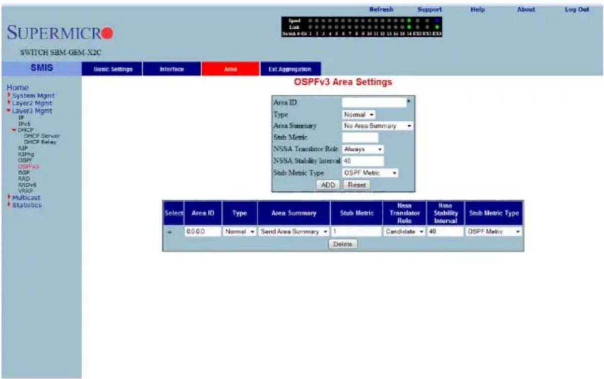
Clicking the AREA tab brings up the OSPFv3 AREA SETTINGS page (Figure 7-126). The parameters for this page are shown in Table 7-100.
Table 7-100. OSPFv3 Area Settings Page Parameters
| Parameter Description | |
| Area ID This parameter uniquely identifies an area. | |
| Type | This parameter indicates whether an area is a Stub area, NSSA, or Standard (normal) area. |
| Area Summary | This parameter controls the import of Inter-Area LSAs into stub areas. This can be noAreaSummary or sendAreaSummary. |
| Stub Metric | This parameter indicates the metric value advertised for the default route into Stub area and NSSA. |
| NSSA Translator Role | This parameter specifies the NSSA Border router's ability to perform NSSA translation of type-7 LSAs into type-5 LSAs. |
| NSSA Stability Interval | This parameter specifies the number of seconds after an elected translator determines its services are no longer required, in which it must continue to perform its translation duties. |
| Stub Metric Type | This parameter specifies the type of metric (OSPFv3 Metric, External Type 1, External Type 2) advertised as a default route. |
OSPF V3 External Aggregation
Figure 7-127. OSPF AS External Aggregation Configuration Page
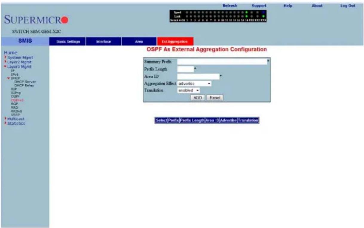
Clicking the EXT AGGREGATION tab brings up the OSPF AS EXTERNAL AGGREGATION CONFIGURATION page (Figure 7-127), which allows you to configure OSPF external aggregation parameters. The parameters for this page are shown in Table 7-101.
Table 7-101. OSPF AS External Aggregation Configuration Page Parameters
| Parameter Description | |
| Network This parameter specifies the external network address. | |
| Mask This parameter specifies the network mask. | |
| Area ID This parameter specifies the Area identifier. | |
Table 7-101. OSPF AS External Aggregation Configuration Page Parameters
| Parameter DescriptionAggregation Effect | This parameter specifies the Aggreation option as one of the following:Advertise– When set toadvertiseand the associated Area ID is 0.0.0.0, then aggregated Type-5 are generated. Otherwise if associated Area ID is x.x.x.x (other than 0.0.0.0), then aggregated Type-7 is generated in NSSA x.x.x.x for the specified range.Do Not Advertise– When set todoNotAdvertise(2)and the associated Area ID is 0.0.0.0, then Type-5 is not generated for the specified range, while aggregated Type-7 are generated in all attached NSSA. While associated Area ID is x.x.x.x (other than 0.0.0.0), then Type-7 are not generated in NSSA x.x.x.x for the specified range.Allow All– When set toallowAlland associated Area ID is 0.0.0.0, then aggregated Type-5 are generated for the specified range. In addition aggregated Type-7 are generated in all attached NSSA, for the specified range.Deny All– When set todenyAllneither Type-5 nor Type-7 will be generated for the specified range. |
| Translation This parameter enables or disables the translation. | |
BGP
The BGP link allows you to configure the BGP protocol. Following are the configuration parameters available to manage BGP through this interface:
• "BGP Basic Settings" on page 7-146
- "BGP Peer Configuration" on page 7-147
• "BGP MED Configuration" on page 7-148
- "Local Preference" on page 7-149
• "BGP Filter" on page 7-151
- "Route Aggregations" on page 7-152
- "Advanced BGP Configuration" on page 7-153
• "BGP Community Management" on page 7-154
BGP Basic Settings
Figure 7-128. BGP Basic Settings Page
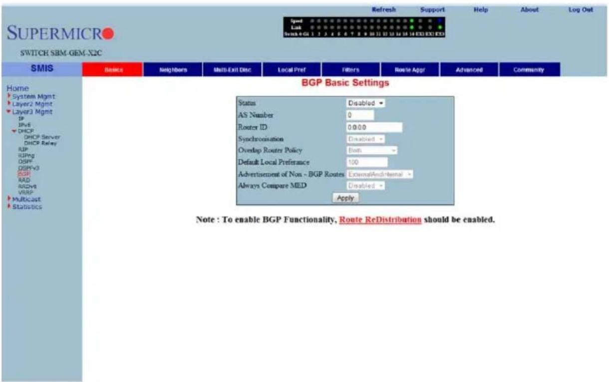
Clicking the BASICS tab brings up the BGP BASIC SETTINGS page (Figure 7-128). The parameters for this page are shown in Table 7-102.
Table 7-102. BGP Basic Settings Page Parameters
| Parameter Description | |
| Status | This parameter specifies the BGP admin status. Using this, the protocol can be enabled/disabled in the switch. |
| AS Number | This parameter specifies the autonomous system to which the switch is connected, which is a read-only field. |
| Synchronization | The synchronization between IGP and BGP can be ensured by enabling this field. |
| Overlap Router Policy | This parameter represents the policy for handling overlapping routes. When an overlapping route is received, depending upon the configured policy, either the less-specific routes or most-specific routes or both are installed in the RIB tree. |
| Default Local Preference | This parameter sets a preference value for the autonomous system path. |
| Advertisement of Non-BGP Routes | You can choose to advertise even the external non-BGP routes by enabling this feature. |
| Always Compare MED | By enabling this feature, you can choose to always compare the MED values of paths from different neighbors for the same prefix, for choosing the best path. |
BGP Peer Configuration
Figure 7-129. BGP Peer Configuration Page
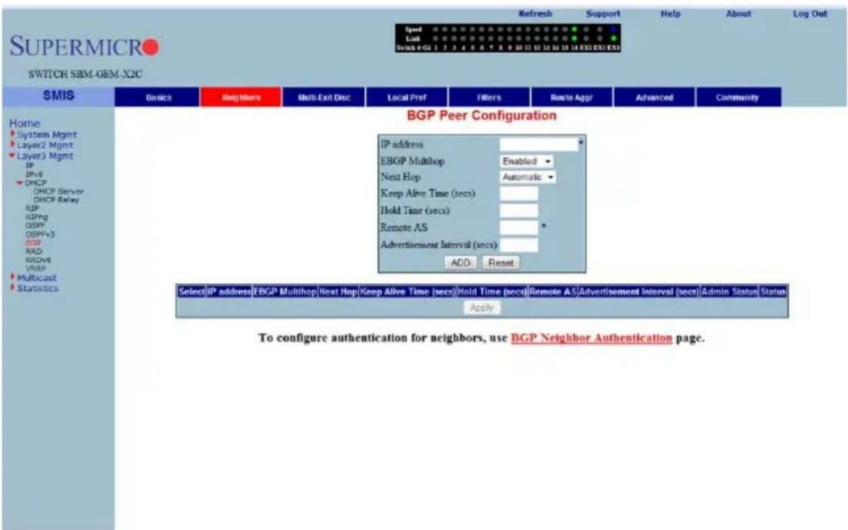
Clicking the NEIGHBORS tab brings up the BGP PEER CONFIGURATION page (Figure 7-129), which allows you to configure BGP Neighbors. The parameters for this page are shown in Table 7-103.
Table 7-103. BGP Peer Configuration Page Parameters
| Parameter Description | |
| IP Address This parameter specifies the IP address of the BGP neighbor. | |
| EBGP MultiHop | By enabling this feature, BGP connections can be established between peers, which are not directly connected. |
| Next Hop | Using this parameter, next Hop can be set as Self or Automatic. By setting this field to Self, you can make the switch the next hop for all the routes that it distributes to its peers. |
| Keep Alive Time (Seconds) | This parameter specifies the maximum time interval between successive updates between any two BGP peers. |
| Hold Time (Seconds) | This parameter specifies the Hold time. This is the timer interval that a BGP will wait, before it decides that a connection to the peer is torn down. |
| Remote AS | This parameter represents the remote autonomous system number. |
| Advertisement Interval (seconds) | This parameter specifies the interval in seconds for the Minimum Route advertisement interval timer. |
| Status This parameter specifies the status of the entry. | |
BGP MED Configuration
Figure 7-130. BGP MED Configuration Page
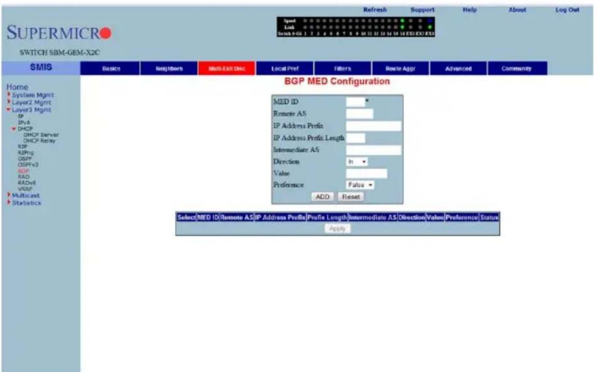
Clicking the MULTI-EXIT DISC tab brings up the BGP MED CONFIGURATION page (Figure 7-130), which allows you to configure the MED value for routes learnt from BGP peers. The parameters for this page are shown in Table 7-104.
Table 7-104. BGP MED Configuration Page Parameters
| Parameter Description | |
| MED ID This parameter specifies the index for this table. | |
| Remote AS | This parameter specifies the AS number from which the route update is received. |
| IP Address Prefix | This parameter specifies the IP address prefix for which the update is received. |
| IP Address Prefix Length This parameter is used to calculate the subnet. | |
| Intermediate AS This parameter represents the intermediate AS between the BGP peers. | |
| Direction | This parameter can be set for the incoming or the outgoing packets using In and Out values. |
| Value | This parameter specifies the MED value to be associated with this path learnt. |
| Preference This parameter is used to enable/disable filtering. | |
| Status This parameter indicates the status of the entry. | |
Local Preference
Figure 7-131. BGP Local Preference Configuration Page
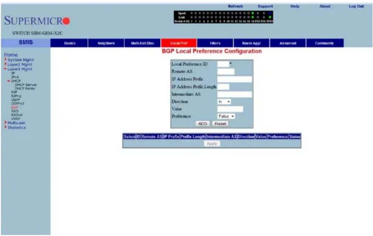
Clicking the LOCAL PREF tab brings up the BGP LOCAL PREFERENCE CONFIGURATION page (Figure 7-131), which allows you to configure the Local Preference value for routes. The parameters for this page are shown in Table 7-105.
Table 7-105. BGP Local Preference Configuration Page Parameters
| Parameter Description | |
| Local Preference ID | This parameter specifies the Local Preference ID, which is the index for this table. |
| Remote AS | This parameter specifies the AS number from which the route update is received. |
| IP Address Prefix | This parameter specifies the IP Address prefix for which the update is received. |
| IP Address Prefix Length This parameter is used to calculate the subnet. | |
| Intermediate AS This parameter represents the intermediate AS between the BGP peers. | |
| Direction | This parameter can be set for the incoming or the outgoing packets using In and Out values. |
| Value | This parameter specifies the Local preference value to be associated with this learnt path. |
| Preference This parameter is used to enable/disable filtering. | |
| Status This parameter specifies the status of the entry. | |
BGP Filter
Figure 7-132. BGP Filter Configuration Page
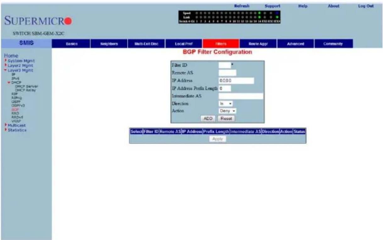
Clicking the FILTERS tab brings up the BGP FILTER CONFIGURATION page (Figure 7-132), which is used to set the filters on the routes being learnt. The parameters for this page are shown in Table 7-106.
Table 7-106. BGP Filter Configuration Page Parameters
| Parameter Description | |
| Filter ID This parameter specifies the filter index. | |
| Remote AS | This parameter specifies the remote AS associated with the BGP peer from which the router is being distributed. |
| IP Address This parameter specifies the IP address for which the route is being learnt. | |
| IP Address Prefix Length | This parameter specifies the prefix length to calculate the Subnet. |
| Intermediate AS This parameter represents the intermediate AS between the BGP peers. | |
| Direction This parameter indicates the direction of the packet. | |
| Action | With this parameter you can choose either to Allow (not to filter) or Deny (Filter) for the above configuration set. |
| Status This parameter specifies the status of the entry. | |
Route Aggregations
Figure 7-133. BGP Route Aggregation Configuration Page
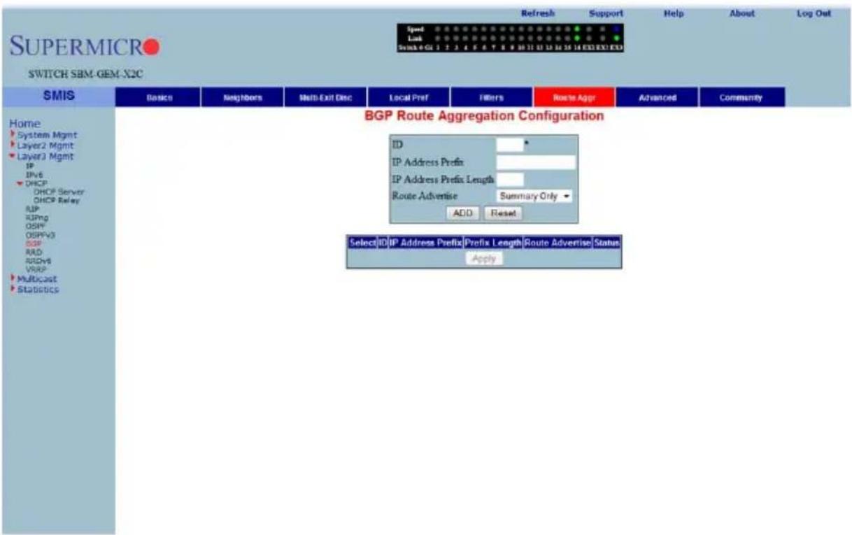
Clicking the ROUTE AGGR tab brings up the BGP ROUTE AGGREGATION CONFIGURATION page (Figure 7-133), which is used to aggregate and configure the routes advertised by BGP. The parameters for this page are shown in Table 7-107.
Table 7-107. BGP Route Aggregation Configuration Page Parameters
| Parameter Description | |
| ID This parameter specifies the index to this table. | |
| IP Address Prefix | This parameter specifies the IP address prefix that needs to be aggregated. |
| IP Address Prefix Length | This parameter, in combination with the IP Prefix, decides the aggregated route to be distributed by this switch. |
| Route Advertise | With this parameter you can either choose to advertise only the aggregated routes by setting Summary only, or choose to advertise all routes by setting All. |
| Status This parameter specifies the status of the entry. | |
Advanced BGP Configuration
Figure 7-134. Advanced BGP Configuration Page
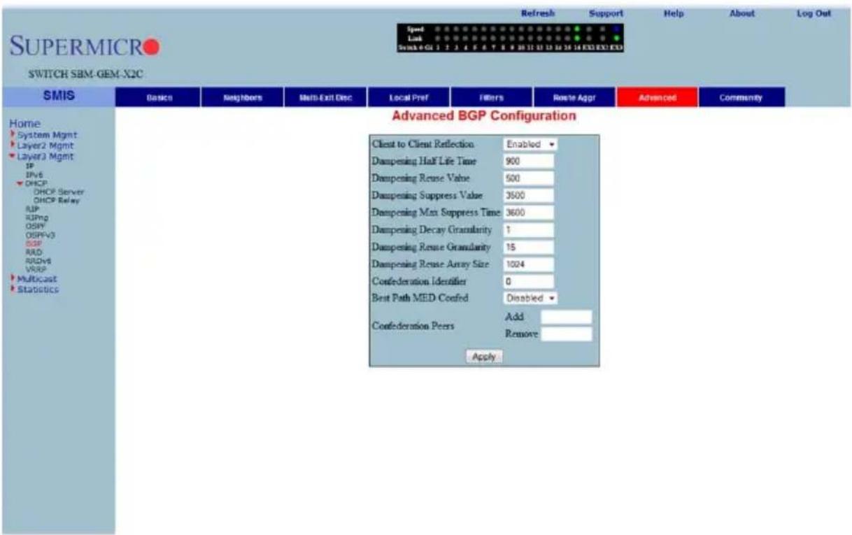
Clicking the ADVANCED tab brings up the ADVANCED BGP CONFIGURATION page (Figure 7-134), which configures dampening and confederation parameters. The parameters for this page are shown in Table 7-108.
Table 7-108. Advanced BGP Configuration Page Parameters
| Parameter Description | |
| Client to Client Reflection | This parameter configures the Route Reflector to support route reflection to client peers.By default, the Route Reflector will reflect routes learnt from a client peer to all other client peers. If required, the administrator can disable this feature by disabling client-to-client reflection.If disabled, then the Route Reflector will not advertise routes learnt from a client peer to other client peers. This occurs when all peers within a cluster are fully-meshed and the client peer itself is able to advertise routes to other clients of the route-reflector. |
| Dampening Half Life Time | This parameter specifies the time (in seconds) after which a penalty is decreased by half. Once a route has been assigned a penalty, the penalty is decreased by half after the half-life time. |
| Dampening Reuse Value | If the penalty associated with a suppressed route falls below this value, the route is re-used. |
| Dampening Suppress Value | A route is suppressed when the penalty associated with the route exceeds this value. |
| Dampening Max Suppress Time | This parameter specifies the maximum time (in seconds) a route can be suppressed. |
| Dampening Decay Granularity | This parameter specifies the time granularity in seconds used to perform all decay computations. |
| Dampening Reuse Granularity | This parameter specifies the time interval between evaluations of the reuse-lists. Each reuse lists corresponds to an additional time increment. |
| Dampening Reuse Array Size | This parameter specifies the size of the reuse index arrays. This size determines the accuracy with which suppressed routes can be placed within the set of reuse lists, when suppressed for a long time. |
| Confederation Identifier | This parameter specifies the BGP confederation identifier. The possible values are between 1 to 65535. Configuring 0 removes the existing configuration. |
| Best Path MED Confed | This parameter enables or disables MED comparison among paths learnt from confed peers. |
| Confederation Peers This parameter configures the ASs that belongs to the confederation. | |
BGP Community Management
Figure 7-135. BGP Community Management Page
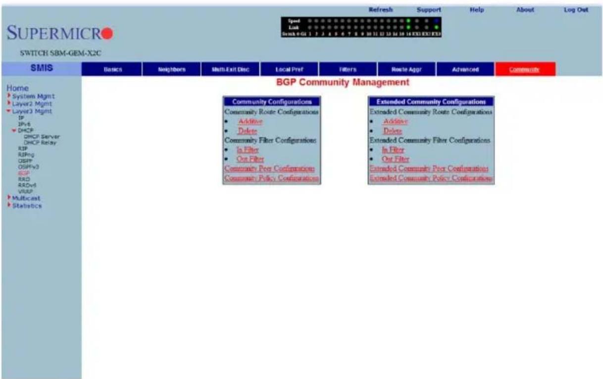
Clicking the COMMUNITY tab brings up the BGP COMMUNITY MANAGEMENT page (Figure 7-135), which configures BGP community and extended community parameters. The parameters for this page are shown in Table 7-109.
Table 7-109. BGP Community Management Page Parameters
| Parameter Description | |
| Community Route Configurations | This parameter configures an entry in the Additive or Delete Community table. |
| Community Filter Configurations | This parameter configures the permit or deny function for the community attribute while receiving or advertising. |
| Community Peer Configurations | This parameter enables or disables advertisement of community attributes to the peer. |
| Community Policy Configurations | This parameter configures the community attribute advertisement policy for a specific destination. |
| Extended Community Route Configurations | This parameter configures an entry in the Additive or Delete Extended Community table. |
| Extended Community Filter Configurations | This parameter configures the permit or deny function for the Extended Community attribute while receiving or advertising. |
| Extended Community Peer Configurations | This parameter enables or disables advertisement of the Extended Community attributes to the peer. |
| Extended Community Policy Configurations | This parameter configures the Extended Community attribute advertisement policy for the specific destination. |
RRD
The RRD link allows you to manage the Route Redistribution with the help of the following pages:
- "RRD Basic Settings" on page 7-156
- "BGP" on page 7-157
- "RIP" on page 7-158
- "OSPF" on page 7-159
RRD Basic Settings
Figure 7-136. RRD Basic Settings Page
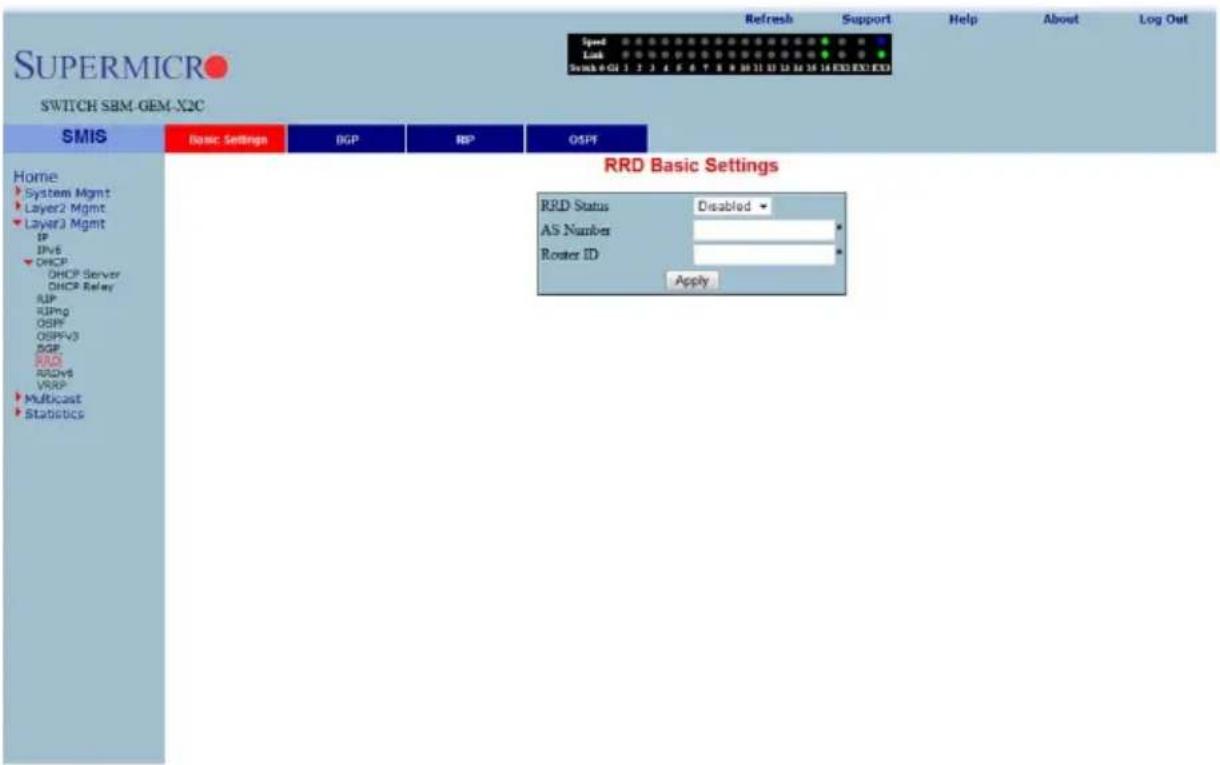
Clicking the BASIC SETTINGS tab brings up the RRD BASIC SETTINGS page (Figure 7-136). The parameters for this page are shown in Table 7-110.
Table 7-110. RRD Basic Settings Page Parameters
| Parameter Description | |
| RRD Status | By enabling this parameter, Route Re-distribution can be enabled in the switch. |
| AS Number | This parameter is used to configure the Router AS number to which this switch belongs. |
| Router ID This parameter represents the Router ID of the switch. | |
BGP
Figure 7-137. RRD BGP Configuration Page
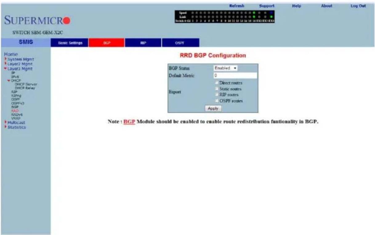
Clicking the BGP tab brings up the RRD BGP CONFIGURATION page (Figure 7-137), which allows you to re-distribute the routes that are learnt through other routing protocols to BGP. The parameters for this page are shown in Table 7-111.
Table 7-111. RRD BGP Configuration Page Parameters
| Parameter Description | |
| BGP Status This parameter | enables or disables redistribution for BGP. |
| Default Metric | This parameter specifies the metric for the routes that are being re-distributed. |
| Import | With this parameter you can choose to import Direct routes, Static routes, RIP routes and/or OSPF routes to BGP. |
RIP
Figure 7-138. RRD RIP Configuration Page
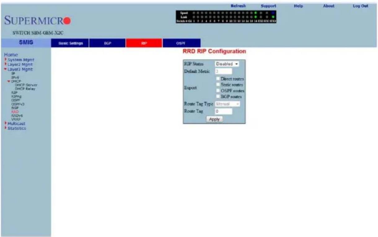
Clicking the RIP tab brings up the RRD RIP CONFIGURATION page (Figure 7-138), which allows you to re-distribute the routes that are learnt through other routing protocols to RIP. The parameters for this page are shown in Table 7-112.
Table 7-112. RRD RIP Configuration Page Parameters
| Parameter Description | |
| RIP Status This parameter enables or disables redistribution for RIP. | |
| Default Metric | This parameter specifies the metric for the routes that are being re-distributed. |
| Import | You can use this parameter to choose to import Direct routes, Static routes, OSPF routes and BGP routes to RIP. |
| Route Tag Type | This parameter describes whether a tag is manually configured or automatically generated. |
| Route Tag | This parameter indicates the route tag in case you configure a manual option for the tag type. |
OSPF
Figure 7-139. RRD OSPF Configuration Page
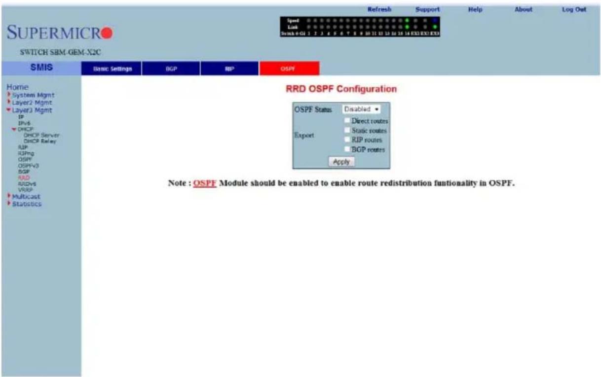
Clicking the OSPF tab brings up the RRD OSPF CONFIGURATION page (Figure 7-139), which allows you to e-distribute the routes that are learnt through other routing protocols to OSPF. The parameters for this page are shown in Table 7-113.
Table 7-113. RRD OSPF Configuration Page Parameters
| Parameter Description | |
| OSPF Status This parameter | enables or disables redistribution for OSPF. |
| Import | With this parameter you can choose to import Direct routes, Static routes, RIP routes and BGP routes to OSPF. |
RRD6
The RRD6 link allows you to perform RRD6 related configuration through the following pages.
- "RRD6 Basic Settings" on page 7-160
- "Filters" on page 7-161
- "RRD V6 OSPF" on page 7-162
- "RRD RIP" on page 7-163
RRD6 Basic Settings
Figure 7-140. RRD6 Basic Settings Page
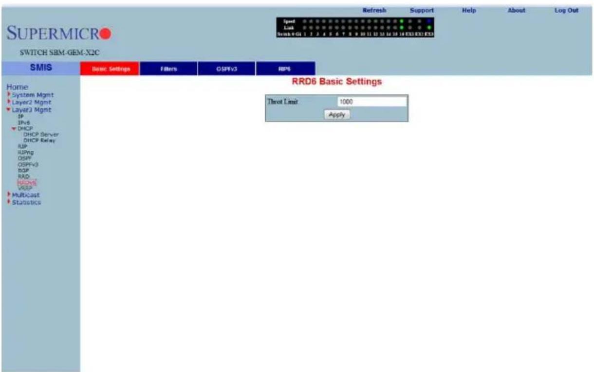
Clicking the BASIC SETTINGS tab brings up the RRD6 BASIC SETTINGS page (Figure 7-140), which has the single parameter option of changing the throat limit for RRD6.
Filters
Figure 7-141. RRD6 Filter Configuration Page
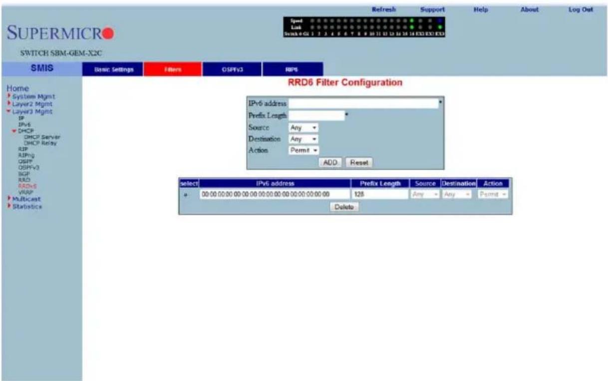
Clicking the FILTERS tab brings up the RRD6 FILTER CONFIGURATION page (Figure 7-141). The parameters for this page are shown in Table 7-114.
Table 7-114. RRD6 Filter Configuration Page Parameters
| Parameter Description | |
| IPv6 address This parameter | specifies the IPv6 Address. |
| Prefix Length | This parameter indicates the length of the prefix (in bits) associated with this entry's IPv6 address. |
| Source This parameter denotes the address of the Source. | |
| Destination This parameter specifies the address of the Destination. | |
| Action | With this parameter you can either choose to Permit (not to filter) or Deny (Filter) for the above configuration set. |
RRD V6 OSPF
Figure 7-142. RRD6 OSPFv3 Configuration Page
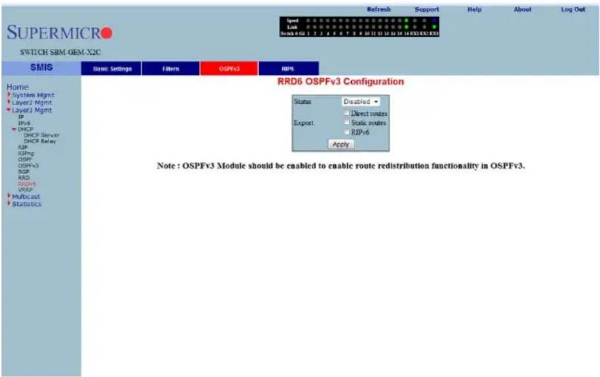
Clicking the OSPFv3 tab brings up the RRD6 OSPFv3 CONFIGURATION page (Figure 7-142). The parameters for this page are shown in Table 7-115.
Table 7-115. RRD6 OSPFv3 Configuration Page Parameters
| Parameter Description | |
| Status This parameter enables or disables redistribution for OSPFv3. | |
| Import | With this parameter you can choose to import Direct routes, Static routes or RIPv6 routes. |
RRD RIP
Figure 7-143. RRD RIPv6 Configuration Page
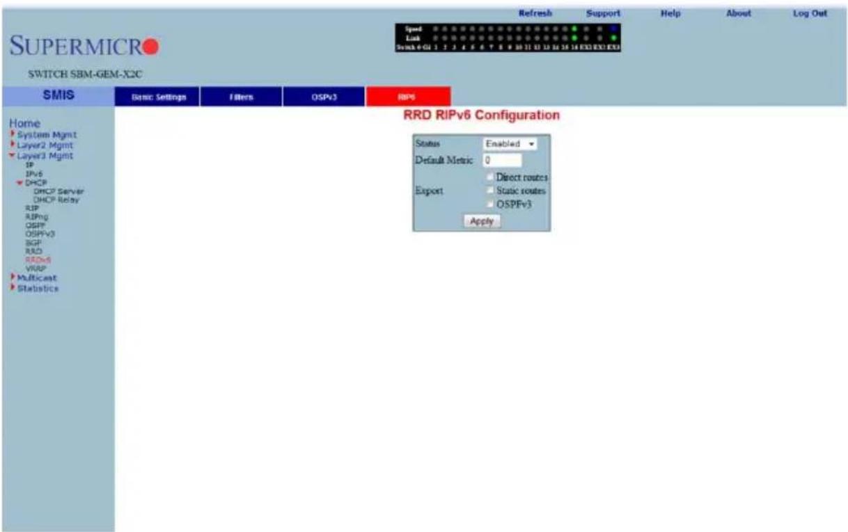
Clicking the RP6 tab brings up the RRD RIPv6 CONFIGURATION page (Figure 7-143). The parameters for this page are shown in Table 7-116.
Table 7-116. RRD RIPv6 Configuration Page Parameters
| Parameter Description | |
| Status This parameter enables or disables redistribution for RIP6. | |
| Default Metric | This parameter specifies the metric for the routes that are being re-distributed. |
| Import | With this parameter you can choose to import Direct routes, Static routes or OSPFv3 routes. |
VRRP
The VRRP link allows you to configure VRRP through the following two pages:
• "VRRP Basic Settings" on page 7-164
• "VRRP Settings" on page 7-165
VRRP Basic Settings
Figure 7-144. VRRP Basic Settings Page
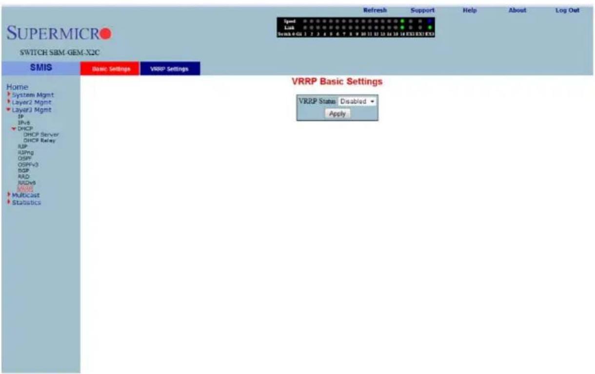
Clicking the BASIC SETTINGS tab brings up the VRRP BASIC SETTINGS page (Figure 7-144), whose single parameter allows you to specify the status of VRRP in the switch.
VRRP Settings
Figure 7-145. VRRP Settings Page
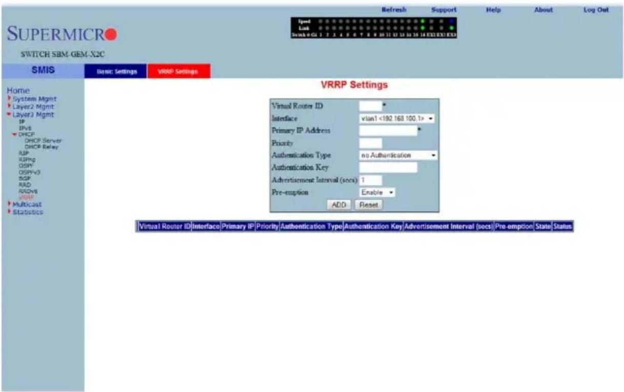
Clicking the VRRP SETTINGS link brings up the VRRP SETTINGS page (Figure 7-145). The parameters for this page are shown in Table 7-117.
Table 7-117. VRRP Settings Page Parameters
| Parameter Description | |
| Virtual Router ID This parameter indicates the Virtual ID associated with each Virtual Router. | |
| Interface | This parameter represents the interface on which the Virtual Router must be configured. |
| Primary IP Address This parameter specifies the P RIMARY IP ADDRESS for the Virtual Router. | |
| Priority | This parameter indicates the PRIORITY for the Virtual Router. The configurable priority value ranges from 1 to 254. |
| Authentication Type This parameter indicates the A UTHENTICATION TYPE for the Virtual Router. | |
| Authentication Key | This parameter indicates the AUTHENTICATION KEY for the Virtual Router. |
| Advertisement Interval (Seconds) | This parameter specifies the time Interval in seconds for sending the advertisement packets. |
| Preempt Mode | This parameter enablesor disables the PREEMPT MODE. |
| State This parameter indicates the current state of the Virtual Router. | |
| Status This parameter specifies the Admin Status of the Virtual Router. | |
7-7 Multicast
Figure 7-146. Multicast Home Page
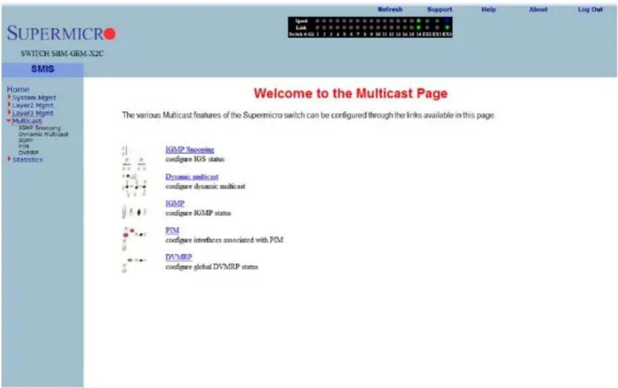
MULTICAST HOME page (Figure 7-146) has links to multicast features in the switch.
GMP Snooping
The GMP Snooping link allows you to configure GMP Snooping through the following pages:
- "IGMP Snooping Configuration" on page 7-167
- "IGMP Snooping Timer" on page 7-168
- "IGMP Snooping Interface" on page 7-169
- "IGMP Snooping VLAN Router" on page 7-170
- "IGMP MAC Forwarding" on page 7-171
IGMP Snooping Configuration
Figure 7-147. IGMP Snooping Configuration Page
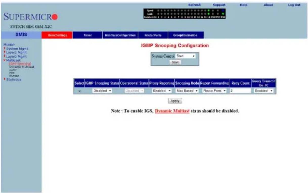
Clicking the BASIC SETTINGS tab brings up the IGMP SNOOPING CONFIGURATION page (Figure 7-147), which allows you to configure IGMP snooping parameters. The parameters for this page are shown in Table 7-118.
Table 7-118. IGMP Snooping Configuration Page Parameters
| Parameter Description | |
| System Control | This parameter Starts or Shutdown IGS in the switch. |
| IGMP Snooping Status | This parameter enables or disables IGMP snooping globally in the switch.To enable IGS, GMRP status must be Disabled. |
| Operational Status | This parameter enables or disables IGMP snooping operationally in the switch. To enable IGS, GMRP status must be Disabled. |
| Proxy Reporting | This parameter indicates whether the proxy reporting in the IGMP snooping switch is to be enabled or disabled. |
| Snooping Mode | This parameter specifies the IGMP snooping multicast forwarding mode, which can be configured using the Destination IP Address or the Destination MAC Address. |
| Report Forwarding | This parameter specifies whether the IGMP reports are forwarded on all ports or only on router ports. |
| Retry Count | This parameter specifies the maximum number of group specific queries sent on a port on the reception of an IGMPv2 leave message. |
| Query Transmit On TC | This parameter allows you to enable or disable query transmit when topology changes. |
IGMP Snooping Timer
Figure 7-148. IGMP Snooping Timer Configuration Page
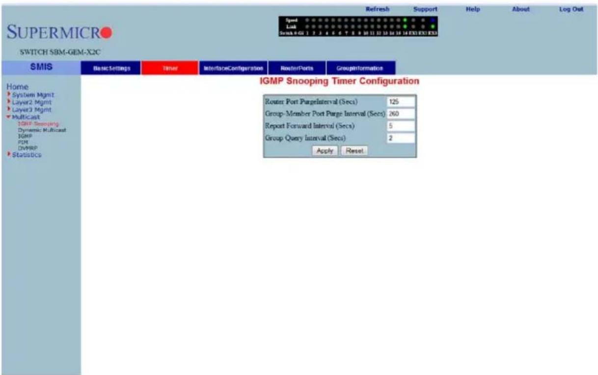
Clicking the TIMER tab brings up the IGMP SNOOPING TIMER CONFIGURATION page (Figure 7-148), which configures IGMP snooping timers. The parameters for this page are shown in Table 7-119.
Table 7-119. IGMP Snooping Timer Configuration Page Parameters
| Parameter Description | |
| Router Port PurgeInterval (Secs) | This parameter specifies the interval for which the learnt router port will be purged. The default value is 125-seconds. |
| Group-Member Port Purge Interval (Secs) | This parameter specifies the interval after which a port gets deleted, if IGMP reports are not received on a port. The default value is 260-seconds. |
| Report Forward Interval (Secs) | This parameter specifies the interval within which the next report messages for the same multicast group will not be forwarded. The default value is 5-seconds. |
| Group Query Interval (Secs) | This parameter specifies the interval within which the switch sends a group specific query on a port when an IGMPv2 leave message is received. The default value is 2-seconds. |
IGMP Snooping Interface
Figure 7-149. IGMP Snooping Interface Configuration Page
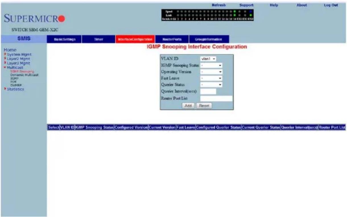
Clicking the INTERFACE CONFIGURATION tab brings up the IGMP SNOOPING INTERFACE CONFIGURATION page (Figure 7-149), which configures IGMP snooping interface specific parameters. The parameters for this page are shown in Table 7-120.
Table 7-120. IGMP Snooping Interface Configuration Page Parameters
| Parameter Description | |
| VLAN ID | This parameter specifies the VLAN ID for which the configuration is to be performed. |
| IGMP Snooping Status | This parameter specifies the status of IGMP snooping in the Switch, which can be enabled or disabled for a specific VLAN. |
| Operating Version | This parameter specifies the operating version of the IGMP snooping switch for a specific VLAN. |
| Fast Leave | This parameter indicates whether the fast leave processing for a specific VLAN, is to be enabled or disabled. |
| Querier Status | This parameter specifies whether the IGMP snooping switch is enabled or disabled as a querier for a specific VLAN. |
| Querier Interval(secs) | This parameter specifies the time period for which general queries are sent by the IGMP snooping switch, when configured as querier on a VLAN. |
| Router Port List This parameter specifies the router port list for a specific VLAN. | |
| Current Version | This parameter specifies the working IGMP Version on the given VLAN. |
| Current Querier Status This parameter specifies the current status of the Querier. | |
IGMP Snooping VLAN Router
Figure 7-150. IGMP Snooping VLAN Router Ports Page
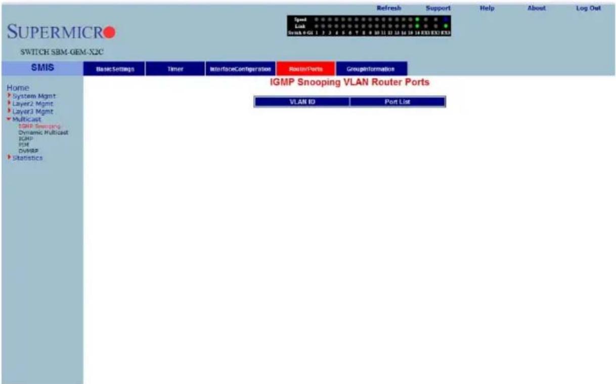
Clicking the ROUTE PORTS tab brings up the IGMP SNOOPING VLAN ROUTER PORTS page (Figure 7-150). The parameters for this page are shown in Table 7-121.
Table 7-121. IGMP Snooping VLAN Router Ports Page Parameters
| Parameter Description | |
| VLAN ID This parameter specifies the VLAN ID. | |
| Port List | This parameter specifies the ports on which routers are connected for a specific VLAN. |
IGMP MAC Forwarding
Figure 7-151. MAC Based Multicast Forwarding Table Page
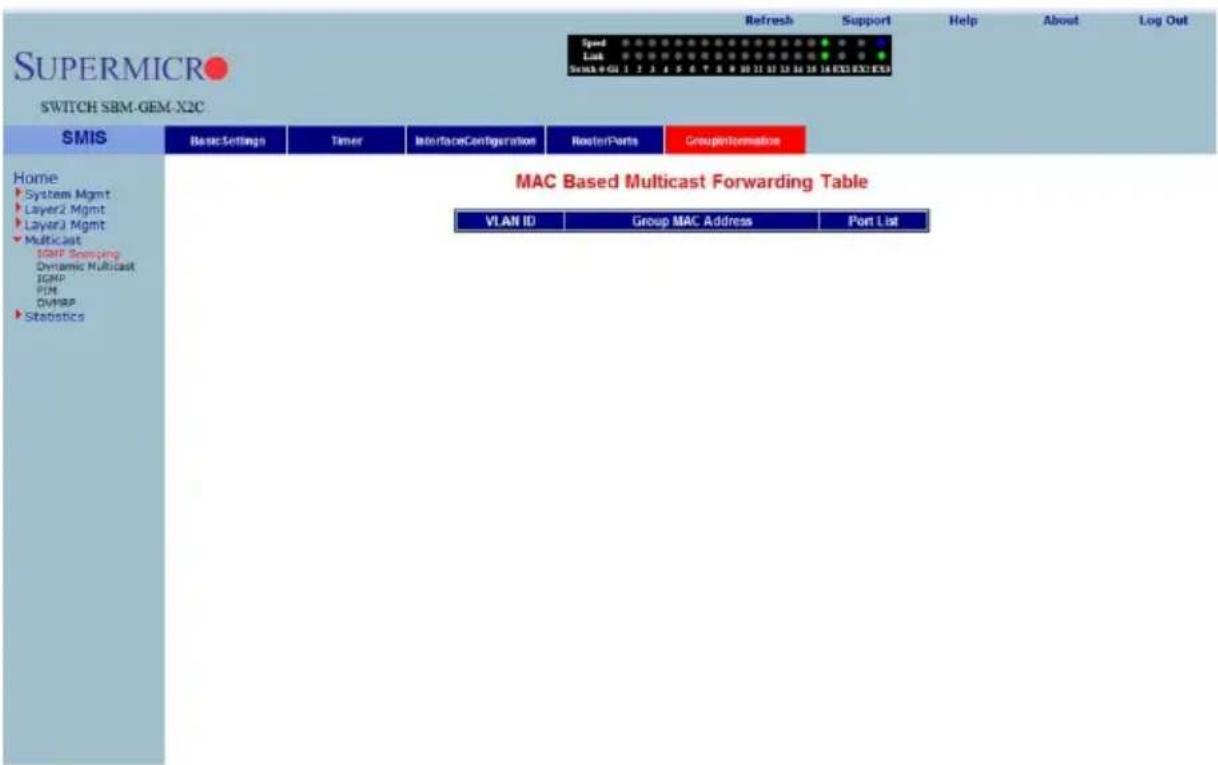
Clicking the GROUP INFORMATION tab brings up the MAC BASED MULTICAST FORWARDING TABLE page (Figure 7-151), which displays either the IP Based or the MAC Based Multicast Forwarding Table depending upon the configuration of the forwarding mode. The parameters for this page are shown in Table 7-122.
Table 7-122. MAC Based Multicast Forwarding Table Page Parameters
| Parameter Description | |
| VLAN ID | This parameter specifies the VLAN ID pertaining to the MAC based multicast forwarding entry. |
| Group MAC Address This parameter specifies the Group MAC Multicast address that is learnt. | |
| Port List This parameter specifies the learnt ports. | |
Dynamic Multicast
The Dynamic Multicast link allows you to configure Dynamic Multicast through the following pages:
• "Global Configuration" on page 7-172
• "Dynamic Multicast Port Configuration" on page 7-173
Global Configuration
Figure 7-152. Dynamic Multicast Global Configuration Page
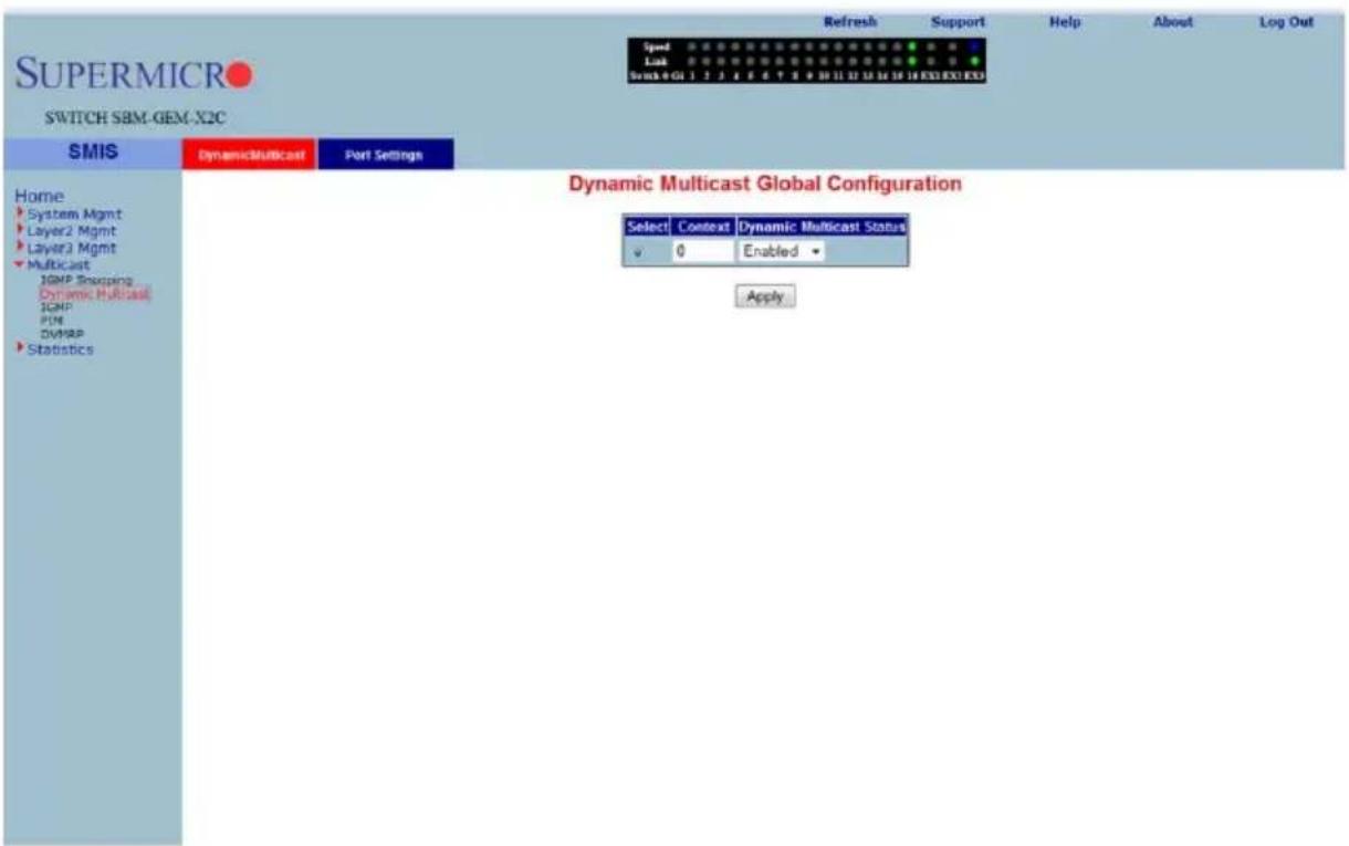
Clicking the DYNAMIC MULTICAST tab brings up the DYNAMIC MULTICAST GLOBAL CONFIGURATION page (Figure 7-152), which allows you to enable or disable the dynamic multicast feature.
Dynamic Multicast Port Configuration
Figure 7-153. Dynamic Multicast Port Configuration Page
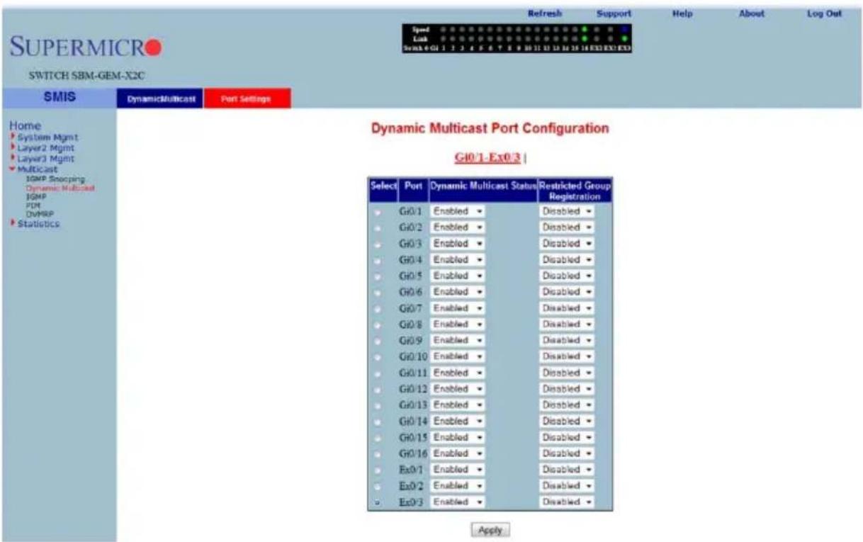
Clicking the PORT SETTINGS tab brings up the DYNAMIC MULTICAST PORT CONFIGURATION page (Figure 7-153), which configures dynamic multicast at the port level. The parameters for this page are shown in Table 7-123.
Table 7-123. Dynamic Multicast Port Configuration Page Parameters
| Parameter Description | |
| Port This parameter specifies the Port index. | |
| Dynamic Multicast Status This parameter enables or disables dynamic multicast on this port. | |
| Restricted Group Registration | This parameter enables or disables RESTRICTED GROUP REGISTRATION on this port. |
IGMP
The IGMP page allows you to configure the IGMP protocol. The IGMP protocol in the switch can be configured through the following pages:
- "Basic Settings" on page 7-174
- "Interface Configuration" on page 7-175
• "Group Information" on page 7-176 - "Source Information" on page 7-177
Basic Settings
Figure 7-154. IGMP Configuration Page
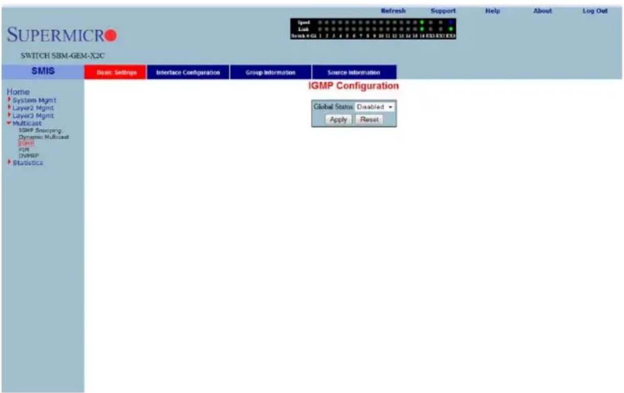
Clicking the IGMP CONFIGURATION tab brings up the IGMP CONFIGURATION page (Figure 7-154), whose single parameter allows you to enable or disable IGMP in the switch.
Interface Configuration
Figure 7-155. IGMP Interface Configuration Page
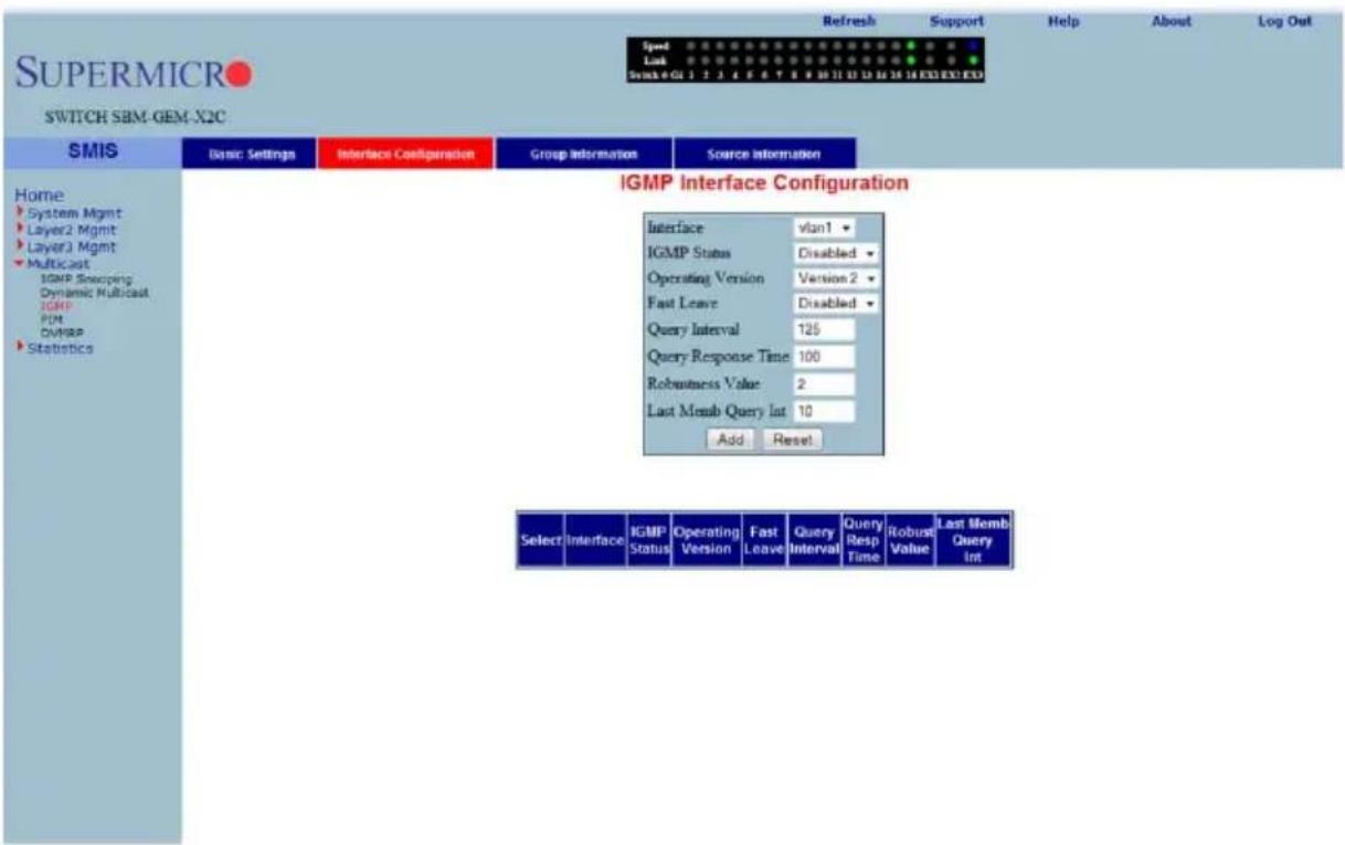
Clicking the INTERFACE CONFIGURATION tab brings up the IGMP INTERFACE CONFIGURATION page (Figure 7-155). The parameters for this page are shown in Table 7-124.
Table 7-124. IGMP Interface Configuration Page Parameters
| Parameter Description | |
| Interface This parameter specifies the interface index. | |
| IGMP Status This parameter specifies the IGMP Status. | |
| Operating Version | With this parameter you can choose to run either in IGMP Version 1, IGMP Version 2 or IGMP Version 3. This can be configured for every interface. |
| Fast Leave | This parameter indicates whether the fast leave processing for a specific interface, is to be enabled or disabled. |
| Query Interval | This parameter indicates the interval between two successive IGMP queries. |
| Query Response Time This parameter specifies the response time for IGMP queries. | |
| Robustness Value This parameter specifies the R OBUSTNESS VALUE on this interface. | |
Group Information
Figure 7-156. IGMP Group Configuration Page
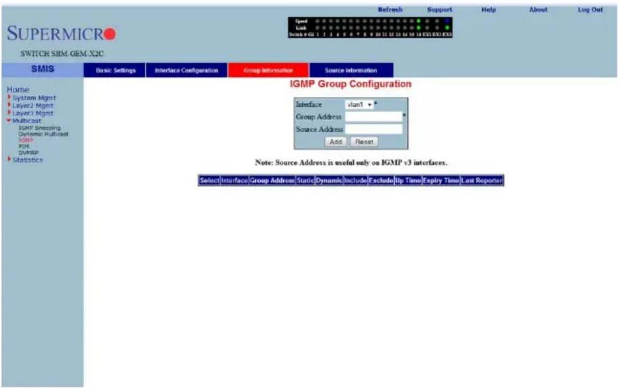
Clicking the GROUP INFORMATION tab brings up the IGMP GROUP CONFIGURATION page (Figure 7-156). The parameters for this page are shown in Table 7-125.
Table 7-125. IGMP Group Configuration Page Parameters
| Parameter Description | |
| Interface This parameter specifies the interface index. | |
| Group Address This parameter specifies the IP multicast group address. | |
| Source Address | This parameter represents the IP Source address.NOTE: Source configuration is allowed only when the operating version is v3 on this interface. |
| Filter Mode | This parameter specifies the FILTER MODE. |
Source Information
Figure 7-157. IGMP Source Information Page
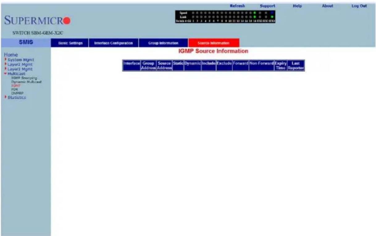
Clicking the SOURCE INFORMATION tab brings up the IGMP SOURCE INFORMATION page (Figure 7-157). The parameters for this page are shown in Table 7-126.
Table 7-126. IGMP Source Information Page Parameters
| Parameter Description | |
| Group Address This parameter specifies the IP multicast group address. | |
| Interface This parameter specifies the interface index. | |
| Source Address This parameter represents the IP Source address. | |
PIM
The PIM link allows you to perform PIM related configuration through the following pages:
- "Basic Settings" on page 7-178
- "Component" on page 7-179
- "Interfaces" on page 7-180
• "Candidate RPs" on page 7-181
• "Threshold" on page 7-182
• "Static RP" on page 7-183
Basic Settings
Figure 7-158. PIM Basic Settings Page
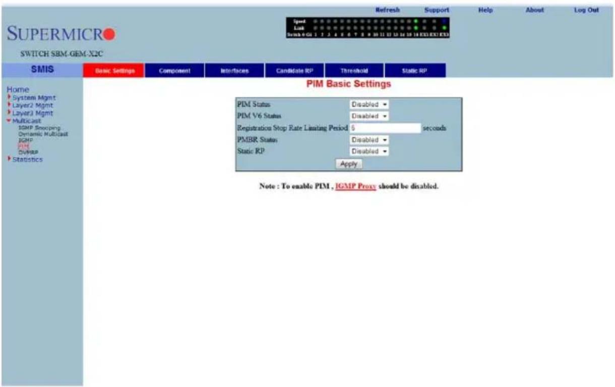
Clicking the BASIC SETTINGS tab brings up the PIM BASIC SETTINGS page (Figure 7-158), which specifies the PIM status in the switch. The parameters for this page are shown in Table 7-127.
Table 7-127. PIM Basic Settings Page Parameters
| Parameter Description | |
| PIM Status | This parameter allows you to enable or disable the PIM status in the switch. |
| PIM V6 Status | This parameter allows you to enable or disable the PIM V6 status in the switch. |
| Registration Stop Rate Limiting Period | This parameter specifies the registration stop rate limiting period in seconds. |
| PMBR Status | This parameter allows you to enable or disable the PMBR status in the switch. |
| Static RP This parameter allows you to enable or disable the Static RP in the switch. | |
Component
Figure 7-159. PIM Component Configuration Page
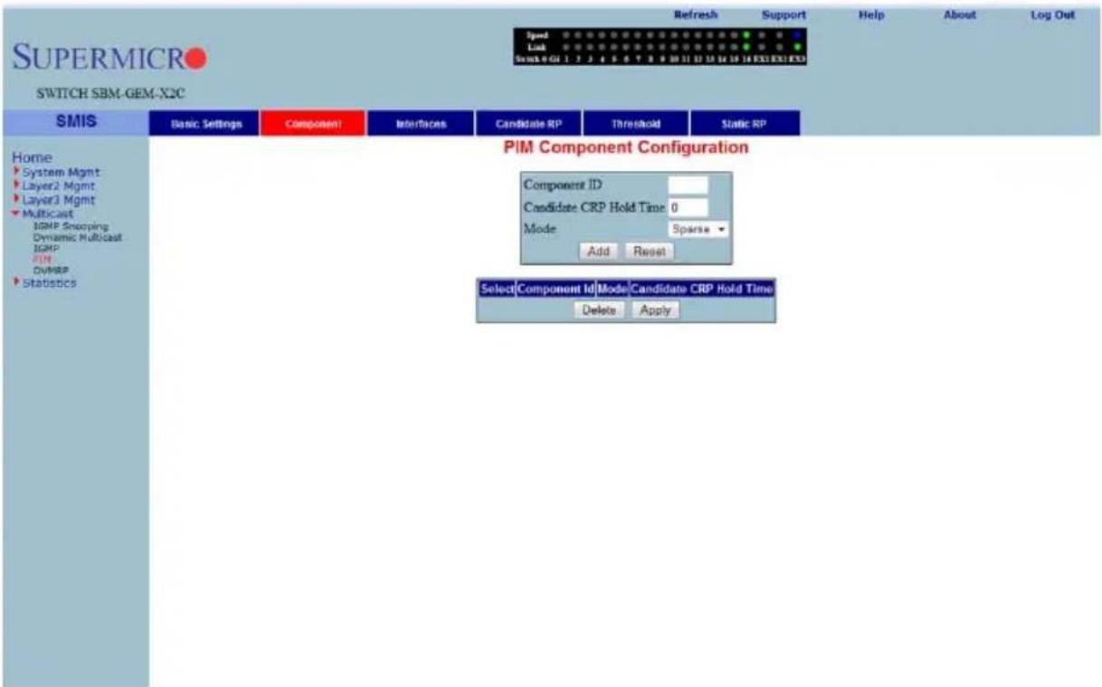
Clicking the COMPONENT tab brings up the PIM COMPONENT CONFIGURATION page (Figure 7-159). The parameters for this page are shown in Table 7-128.
Table 7-128. PIM Component Configuration Page Parameters
| Parameter Description | |
| Component ID This parameter specifies a number uniquely identifying the component. | |
| Candidate CRP Hold Time | This parameter specifies the hold time of the component when it is a candidate RP in the local domain. |
| Mode | This parameter specifies the mode of the component. It can be Sparse or Dense. |
| Parameter DescriptionBSR Address | This parameter specifies the IP address of the bootstrap router for the local PIM region, which is a read-only field. |
| BSR Expiry Time | This parameter indicates the minimum time remaining before the bootstrap router in the local domain is declared down, which is a read-only field. |
Interfaces
Figure 7-160. PIM Interface Configuration Page
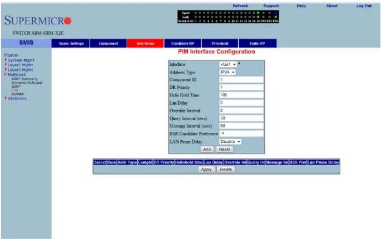
Clicking the INTERFACES tab brings up the PIM INTERFACE CONFIGURATION page (Figure 7-160). The parameters for this page are shown in Table 7-129.
Table 7-129. PIM Interface Configuration Page Parameters
| Parameter Description | |
| Interface This parameter specifies the interface index. | |
| Component ID This parameter specifies a number uniquely identifying the component. | |
| Hello Interval (Seconds) | This parameter specifies the time interval between two successive Hello messages being sent by PIM on this interface. |
| Join Prune Interval (Seconds) | This parameter specifies the time interval between two successive Join/Prune messages being sent by PIM on this interface. |
| CBSR Preference | This parameter indicates the preference value for the local interface as a candidate bootstrap router. |
| Row Status This parameter | indicates the operational status of the entry. |
Candidate RPs
Figure 7-161. Candidate RP Configuration Page
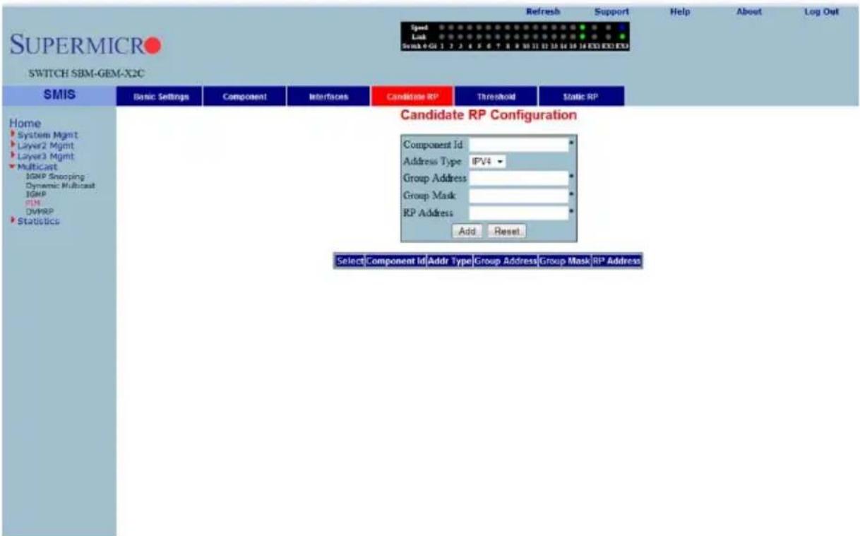
Clicking the CANDIDATE RPs tab brings up the CANDIDATE RP CONFIGURATION page (Figure 7-161). The parameters for this page are shown in Table 7-130.
Table 7-130. Candidate RP Configuration Page Parameters
| Parameter Description | |
| Component ID This parameter specifies a number uniquely identifying the component. | |
| Group Address | This parameter represents the multicast group, for which the switch advertises itself as the candidate RP. |
| Group Mask | This parameter specifies the subnet mask, which when combined with the group address gives the group prefix. |
| RP Address This parameter represents the IP address of the Candidate-RP. | |
Threshold
Figure 7-162. PIM Threshold Configuration Page
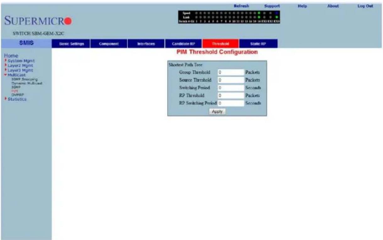
Clicking the THRESHOLD tab brings up the PIM THRESHOLD CONFIGURATION page (Figure 7-162). The parameters for this page are shown in Table 7-131.
Table 7-131. PIM Threshold Configuration Page Parameters
| Parameter Description | |
| Group Threshold | This parameter is a bits-per-second (BPS) value that when it exceeds a certain value, initiates source specific counters for a particular group. |
| Source Threshold | This parameter is a bits-per-second (BPS) value that when exceeds a certain value, initiates switching to shortest path tree. |
| Switching Period | This parameter specifies the time interval that the data rate is monitored for, initiating the counters or for switching to SPT. |
| RP Threshold | When the number of registered packets received exceeds this threshold value, RP initiates switching to SPT. |
| RP Switching Period | This parameter specifies the time interval for which the registered packets are monitored to initiate switching to SPT. |
Static RP
Figure 7-163. Static RP Configuration Page
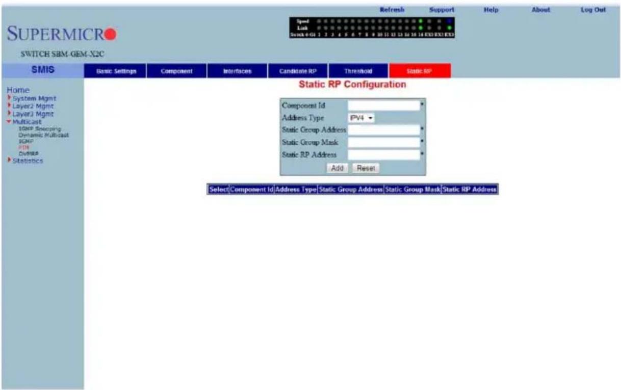
Clicking the STATIC RP tab brings up the STATIC RP CONFIGURATION page (Figure 7-163), which configure static PIM RPs (Rendezvous Points). The parameters for this page are shown in Table 7-132.
Table 7-132. Static RP Configuration Page Parameters
| Parameter Description | |
| Component ID This parameter specifies a number uniquely identifying the component. | |
| Address Type This parameter chooses the IPv4 or IPv6 address type. | |
| Static Group Address | This parameter represents the multicast group, for which the switch advertises itself as the candidate RP. |
| Static Group Mask | This parameter specifies the subnet mask, which when combined with the group address gives the group prefix. |
| Static RP Address This parameter represents the IP address of the candidate RP. | |
DVMRP
The DVMRP page allows you to configure the DVMRP protocol using the following pages:
• "DVMRP Basic Settings" on page 7-184
- "Interfaces" on page 7-185
DVMRP Basic Settings
Figure 7-164. DVMRP Basic Settings Page
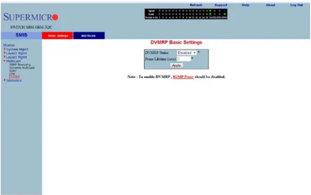
Clicking the BASIC SETTINGS tab brings up the DVMRP BASIC SETTINGS page (Figure 7-164). The parameters for this page are shown in Table 7-133.
Table 7-133. DVMRP Basic Settings Page Parameters
| Parameter Description | |
| DVMRP Status DVMRP can | be enabled or disabled in the switch using this field. |
| Prune Lifetime (Seconds) | This parameter represents the Prune Life Time Configuration value. |
Interfaces
Figure 7-165. DVMRP Interface Settings Page
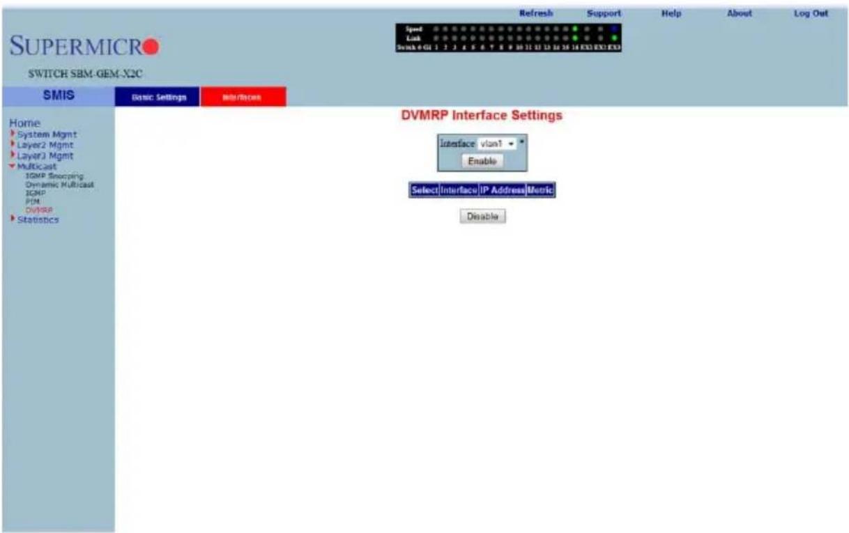
Clicking the INTERFACES tab brings up the DVMRP INTERFACE SETTINGS page (Figure 7-165), which displays the various parameters XXXXXX. The parameters for this page are shown in Table 7-134.
Table 7-134. DVMRP Interface Settings Page Parameters
| Parameter Description | |
| Interface This parameter specifies the Interface Index. | |
| IP Address | This parameter specifies the IP Address of the interface, which is a read-only field. |
| Metric | This parameter specifies the distance metric for this interface, which is used to calculate distance vectors. |
7-8 Statistics
Figure 7-166. Statistics Home Page
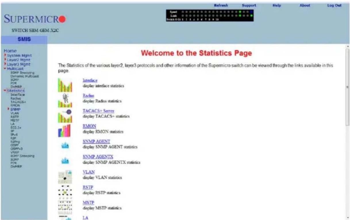
The STATISTICS HOME page (Figure 7-166) contains links to all statistical information for all switch features.
Interface
The Interface link allows you to configure the following pages:
- "Interface Statistics" on page 7-187
• "Ethernet Statistics" on page 7-188
Interface Statistics
Figure 7-167. Interface Statistics Page
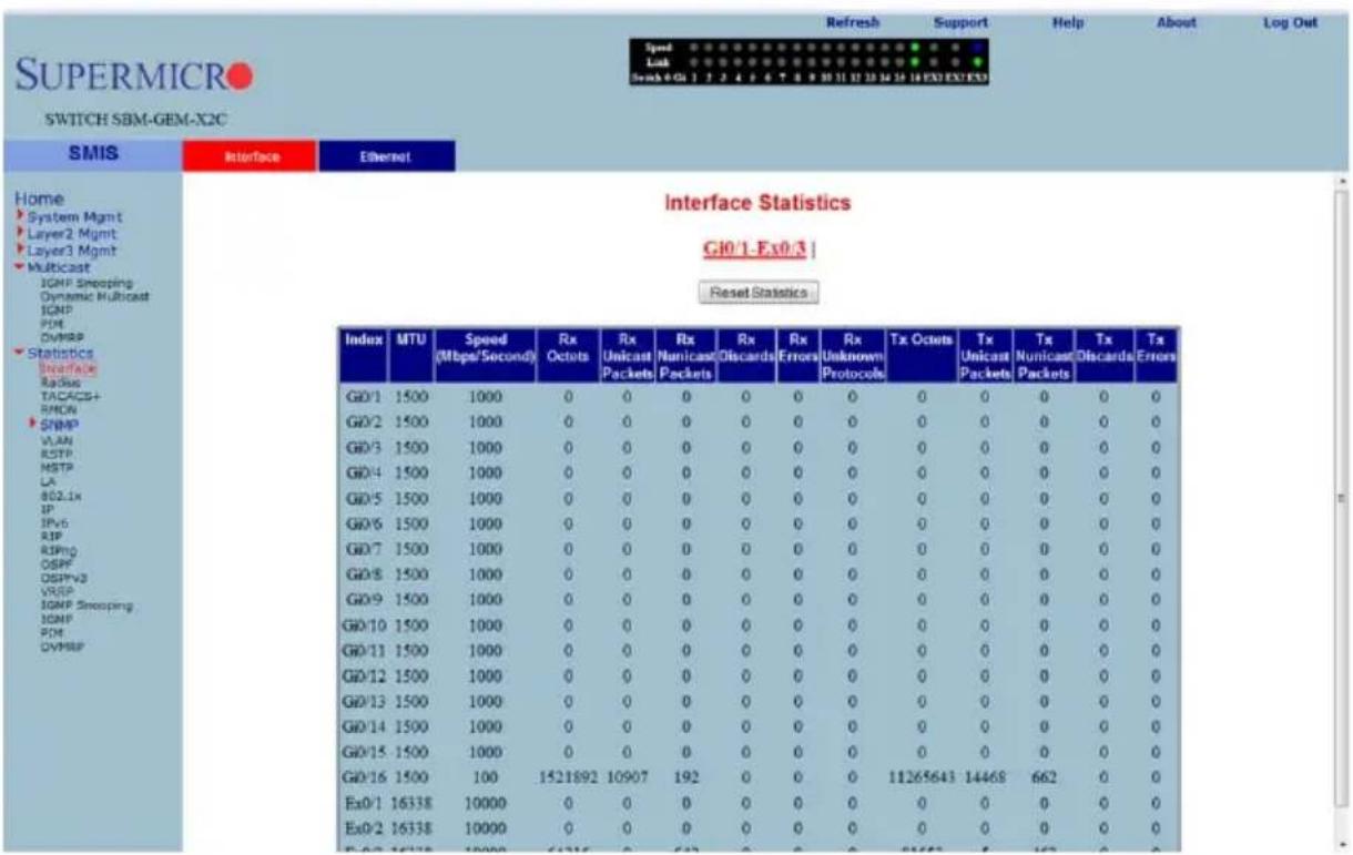
Clicking the INTERFACE tab brings up the INTERFACE STATISTICS page (Figure 7-167). The parameters for this page are shown in Table 7-135.
Table 7-135. Interface Statistics Page Parameters
| Parameter Description | |
| Index This parameter specifies the Port index. | |
| MTU This parameter specifies the Max Transfer Unit bytes. | |
| Speed (Bits Per Second) This parameter specifies the port speed in bits per second. | |
| Received Octets This parameter specifies the number of bytes received. | |
| Received Unicast Packets This parameter specifies the number of unicast packets received. | |
| Received Nunicast Packets This parameter specifies the number of non-unicast packets received. | |
| Received Discards This parameter specifies the number of packets discarded due to errors. | |
| Received Errors This parameter specifies the number of packets received with errors. | |
| Received Unknown Protocols | This parameter specifies the number of packets received with an unknown protocol. |
| Transmitted Octets This parameter specifies the number of bytes transmitted. | |
| Transmitted Unicast Packets | This parameter specifies the number of unicast packets transmitted. |
| Transmitted Nunicast Packets | This parameter specifies the number of non-unicast packets transmitted. |
| Transmitted Discards | This parameter specifies the number of packets discarded due to transmit errors. |
| Transmitted Errors This parameter specifies the number of transmit errors. | |
Ethernet Statistics
Figure 7-168. Ethernet Statistics Page
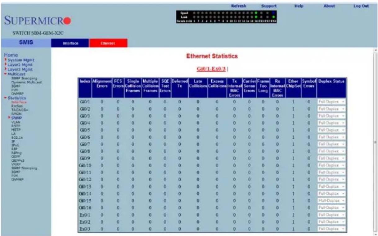
Clicking the ETHERNET tab brings up the ETHERNET STATISTICS page (Figure 7-168). The parameters for this page are shown in Table 7-136.
Table 7-136. Ethernet Statistics Page Parameters
| Parameter Description | |
| Index This parameter specifies the port index. | |
| Alignment Errors | This parameter specifies the number of alignment errors. Alignment errors generally indicate improper byte-alignment for Ethernet packets. |
| FCS Errors | This parameter specifies the number of packets received with checksum errors. |
| Single Collision Frames | This parameter specifies the number of frames received with a collision. |
| Multiple Collision Frames | This parameter specifies the number of frames received with multiple collisions. |
| SQE Test Errors | This parameter specifies the number of Signal Quality Errors that have occurred. |
| Deferred Transmissions | This parameter specifies the number of frames deferred for transmissions due to network sense. |
| Late Collisions | This parameter specifies the number of frames faced late collisions. A collision is considered late if the jam occurs after 512 bit-times, or 64 bytes. |
| Excess Collisions | This parameter specifies the number of excess collisions detected. Excessive Collisions describe the situation where a station has tried 16 times to transmit without success and discards the frame. This means that there is excessive traffic on the network and this must be reduced. |
| Transmitted Internal MAC Errors | This parameter specifies the number of MAC transmit errors. |
| Carrier Sense Errors This parameter specifies the number of carrier sense errors. | |
| Frame Too Long | This parameter specifies the number of too long frames received for transmission. |
| Received Internal MAC Errors | This parameter specifies the number of MAC received errors. |
| Symbol Errors This parameter specifies the number of symbol errors. | |
| Duplex Status This parameter specifies the current status of duplex. | |
Radius
Figure 7-169. Radius Server Statistics Page
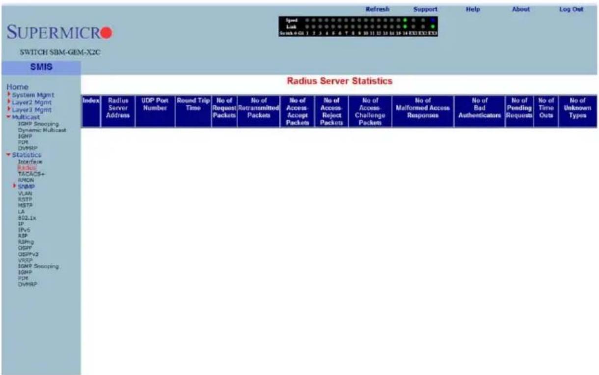
Clicking the RADIUS link brings up the RADIUS SERVER STATISTICS page (Figure 7-169). The parameters for this page are shown in Table 7-137.
Table 7-137. Radius Server Statistics Page Parameters
| Parameter Description | |
| Index This parameter specifies the port index. | |
| Radius Server Address | This parameter specifies the RADIUS SERVER ADDRESS. |
| UDP Port Number This parameter specifies the UDP PORT NUMBER. | |
| Round Trip Time | This parameter displays the ROUND TRIP TIME in seconds. |
| No of Request Packets This parameter specifies the number of request packets transmitted. | |
| No of Retransmitted Packets | This parameter specifies the number of packets retransmitted. |
| No of Access-Accept Packets | This parameter specifies the number of accept packets. |
| No of Access-Reject Packets | This parameter specifies the number of reject packets. |
| No of Access-Challenge Packets | This parameter specifies the number of challenge packets. |
| No of Malformed Access Responses | This parameter specifies the number of invalid access responses received. |
| No of Bad Authenticators This parameter specifies the number of failed authentications. | |
| No of Pending Requests This parameter specifies the number of currently pending requests. | |
| No of Time Outs This parameter specifies the number of time outs that have happened. | |
| No of Unknown Types | This parameter specifies the number of unknown types that have been received. |
TACACS+ Statistics
Figure 7-170. TACACS+ Statistics Page
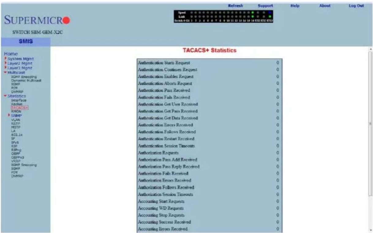
Clicking the TACACS+ link brings up the TACACS+ STATISTICS page (Figure 7-170). The parameters for this page are shown in Table 7-138.
Table 7-138. TACACS+ Statistics Page Parameters
| Parameter Description | |
| Authentication Starts Request | This parameter specifies the number of authentication starts requested. |
| Authentication Continues Request | This parameter specifies the number of authentication continues requested. |
| Authentication Enables Request | This parameter specifies the number of authentication enables requested. |
| Authentication Aborts Request | This parameter specifies the number of authentication aborts requested. |
| Authentication Pass Received | This parameter specifies the number of authentication passes received. |
| Authentication Fails Received | This parameter specifies the number of authentication fails received. |
| Authentication Get User Received | This parameter specifies the number of authentication get users received. |
| Authentication Get Pass Received | This parameter specifies the number of authentication get passes received. |
| Authentication Get Data Received | This parameter specifies the number of authentication get datas received. |
| Authentication Errors Received | This parameter specifies the number of authentication errors received. |
| Authentication Follows Received | This parameter specifies the number of authentication follows received. |
| Authentication Restart Received | This parameter specifies the number of authentication restarts received. |
| Authentication Session Timeouts | This parameter specifies the number of authentication session timeouts received. |
| Authorization Requests | This parameter specifies the number of authentication requests received. |
| Authorization Pass Add Received | This parameter specifies the number of authentication pass adds received. |
| Authorization Pass Reply Received | This parameter specifies the number of authentication pass replies received. |
| Authorization Fails Received | This parameter specifies the number of authentication fails received. |
| Authorization Errors Received | This parameter specifies the number of authentication errors received. |
| Authorization Follows Received | This parameter specifies the number of authentication follows received. |
| Authorization Session Timeouts | This parameter specifies the number of authentication session timeouts. |
| Accounting Start Requests | This parameter specifies the number of accounting start requests. |
| Accounting WD Requests This parameter specifies the number of accounting WD requests. | |
| Accounting Stop Requests This parameter specifies the number of accounting stop requests. | |
| Accounting Success Received | This parameter specifies the number of accounting successes received. |
| Accounting Errors Received | This parameter specifies the number of accounting errors received. |
| Accounting Follows Received | This parameter specifies the number of accounting follows received. |
| Accounting Session Timeouts | This parameter specifies the number of accounting sessions received. |
| Malformed Packets Received | This parameter specifies the number of malformed packets received. |
| Socket Failures This parameter specifies the number of socket failures. | |
| Connection Failures This parameter specifies the number of connection failures. | |
RMON Ethernet Statistics
Figure 7-171. RMON Ethernet Statistics Page
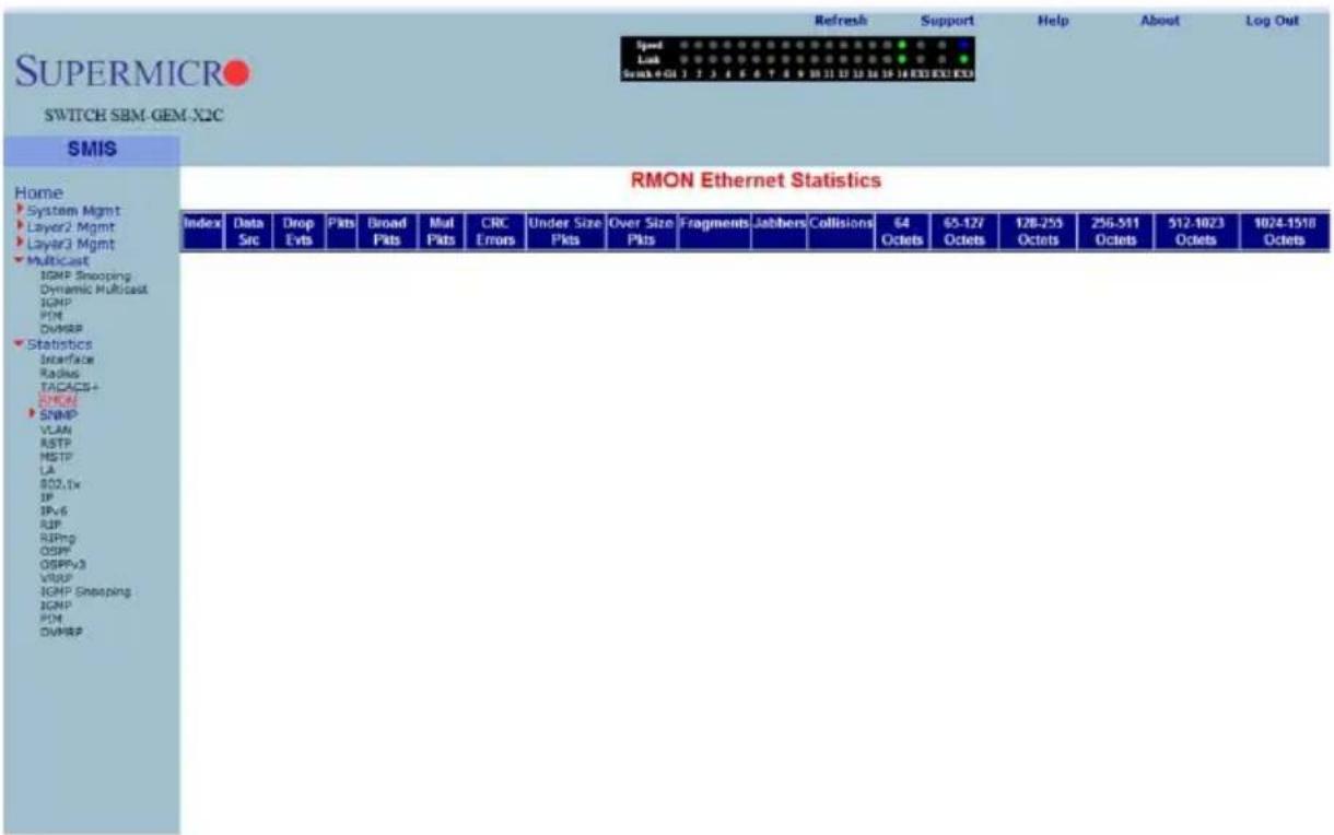
Clicking the RMON link brings up the RMON ETHERNET STATISTICS page (Figure 7-171), which displays RMON Ethernet statistics information. The parameters for this page are shown in Table 7-139.
Table 7-139. RMON Ethernet Statistics Page Parameters
| Parameter Description | |
| Index This parameter specifies the index. | |
| Port This parameter specifies the port. | |
| Octets This parameter specifies the number of octets received. | |
| Packets This parameter specifies the number of packets received. | |
| Broadcast Packets This parameter specifies the number of broadcast packets received. | |
| Multicast Packets | This parameter specifies the number of multicast packets received. |
| CRC Errors This parameter specifies the number of packets received with crc errors. | |
| Under Size Packets This parameter specifies the number of under size packets received. | |
| Over Size Packtes This parameter specifies the number of over size packets received. | |
| Fragments This parameter specifies the number of fragments received. | |
| Jabbers This parameter specifies the number of jabbers. | |
| Collisions This parameter specifies the number of collisions. | |
| 64 Octets | This parameter specifies the number of Ethernet packets received with a size less than 64 bytes. |
| 65-127 Octets | This parameter specifies the number of Ethernet packets received with a size between 65 and 127 bytes. |
| 128-255 Octets | This parameter specifies the number of Ethernet packets received with a size between 128 and 255 bytes. |
| 256-511 Octets | This parameter specifies the number of Ethernet packets received with a size between 256 and 511 bytes. |
| 512-1023 Octets | This parameter specifies the number of Ethernet packets received with a size between 512 and 1023 bytes. |
| 1024-1518 Octets | This parameter specifies the number of Ethernet packets received with a size between 1024 and 1518 bytes. |
SNMP Statistics
The SNMP Statistics link allows you to configure SNMP Statistics through the following pages:
- "Agent" on page 7-196
• "SNMP AgentX" on page 7-197
Agent
Figure 7-172. SNMP Statistics Page
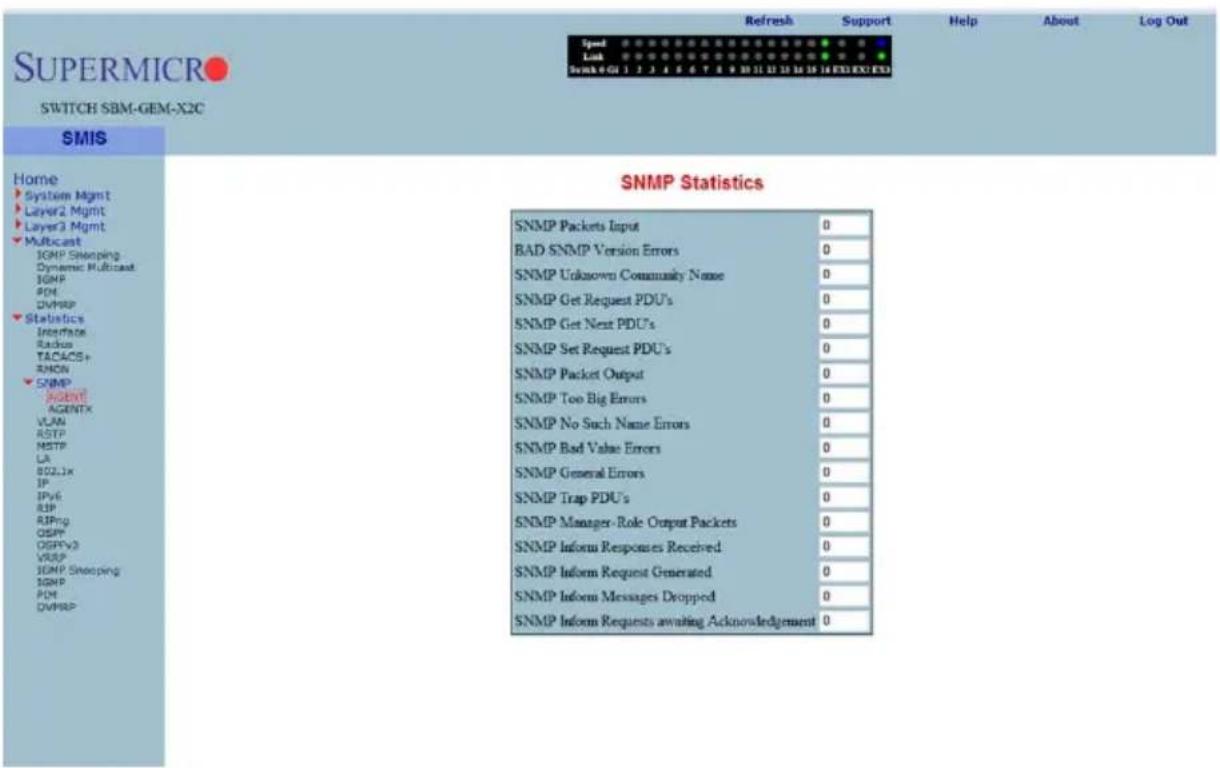
Clicking the SNMP AGENT link brings up the SNMP STATISTICS page (Figure 7-172), which displays SNMP statistics. The parameters for this page are shown in Table 7-140.
Table 7-140. SNMP Statistics Page Parameters
| Parameter Description | |
| SNMP Packets Input This parameter specifies the number of SNMP packets input. | |
| BAD SNMP Version Errors | This parameter specifies the number of BAD SNMP version errors. |
| SNMP Unknown Community Name | This parameter specifies the number of SNMP unknown community names. |
| SNMP Get Request PDU's | This parameter specifies the number of SNMP Get Request PDU's. |
| SNMP Get Next PDU's This parameter specifies the number of SNMP Get Next PDU's. | |
| SNMP Set Request PDU's | This parameter specifies the number of SNMP Set Request PDU's. |
| SNMP Packet Output This parameter specifies the number of SNMP packets output. | |
| SNMP Too Big Errors This parameter specifies the number of SNMP Too Big errors, | |
| SNMP No Such Name Errors | This parameter specifies the number of SNMP No Such Name errors, |
| SNMP Bad Value Errors This parameter specifies the number of SNMP Bad Value errors. | |
| SNMP General Errors This parameter specifies the number of SNMP General errors. | |
| SNMP Trap PDU's This parameter specifies the number of SNMP Trap PDU's. | |
| SNMP Manager-Role Output Packets | This parameter specifies the number of SNMP Manager-Role Output packets. |
| SNMP Inform Responses Received | This parameter specifies the number of SNMP Inform responses received. |
| SNMP Inform Request Generated | This parameter specifies the number of SNMP Inform requests generated. |
| SNMP Inform Messages Dropped | This parameter specifies the number of SNMP Inform messages dropped. |
| SNMP Inform Requests awaiting Acknowledgement | This parameter specifies the number of SNMP Inform requests awaiting acknowledgement. |
SNMP AgentX
Clicking the AGENTX link brings up the AGENTX SUBAGENT STATISTICS page (not shown), which displays Agentx Subagent information. The parameters for this page are shown in Table 7-141.
Table 7-141. Agentx Subagent Statistics Page Parameters
| Parameter Description | |
| Transmit Statistics | |
| Transmitted Packets This parameter specifies the number of packets transmitted. | |
| Open PDU This parameter specifies the number of open PDUs transmitted. | |
| IndexAlloc PDU This parameter specifies the number of IndexAlloc PDUs transmitted. | |
| Register PDU This parameter specifies the number of register PDUs transmitted. | |
| Add Agent Caps PDU This parameter specifies the number of add agent caps PDUs transmitted. | |
| Notify PDU This parameter specifies the number of notify PDUs transmitted. | |
| Ping PDU This parameter specifies the number of ping PDUs transmitted. | |
| Remove Agent Caps PDU | This parameter specifies the number of remove agent caps PDUs transmitted. |
| IndexDeAlloc PDU | This parameter specifies the number of IndexDeAlloc PDUs transmitted. |
| Parameter | Description |
| UnRegister PDU This parameter specifies the number of unregister PDUs transmitted. | |
| Close PDU This parameter specifies the number of close PDUs transmitted. | |
| Response PDU This parameter specifies the number of response PDUs transmitted. | |
| Receive Statistics | |
| Received Packets This parameter specifies the number of packets received. | |
| Get Request PDU This parameter specifies the number of get request PDUs received. | |
| Get Next PDU This parameter specifies the number of get next PDUs received. | |
| Get Bulk PDU This parameter specifies the number of get bulk PDUs received. | |
| TestSet PDU This parameter specifies the number of test set PDUs received. | |
| Commit PDU This parameter specifies the number of commit PDUs received. | |
| Cleanup PDU This parameter specifies the number of cleanup PDUs received. | |
| Undo PDU This parameter specifies the number of undo PDUs received. | |
| Dropped Packets This parameter specifies the number of dropped packets. | |
| Parse Drop Errors | This parameter specifies the number of received PDUs dropped due to parse errors. |
| Open Fail Errors This parameter specifies the number of open fail PDUs received. | |
| Close PDU This parameter specifies the number of close PDUs received. | |
| Response PDU This parameter specifies the number of response PDUs received. | |
VLAN
The VLAN link allows you to view VLAN statistics through the following pages:
- "Current DB" on page 7-199
• "VLAN Port Statistics" on page 7-200
• "VLAN Multicast Table" on page 7-201
• "VLAN Counter Statistics" on page 7-202
• "VLAN Capabilities" on page 7-203
• "VLAN FDB Entries" on page 7-204
Current DB
Figure 7-173. VLAN Current Database Page
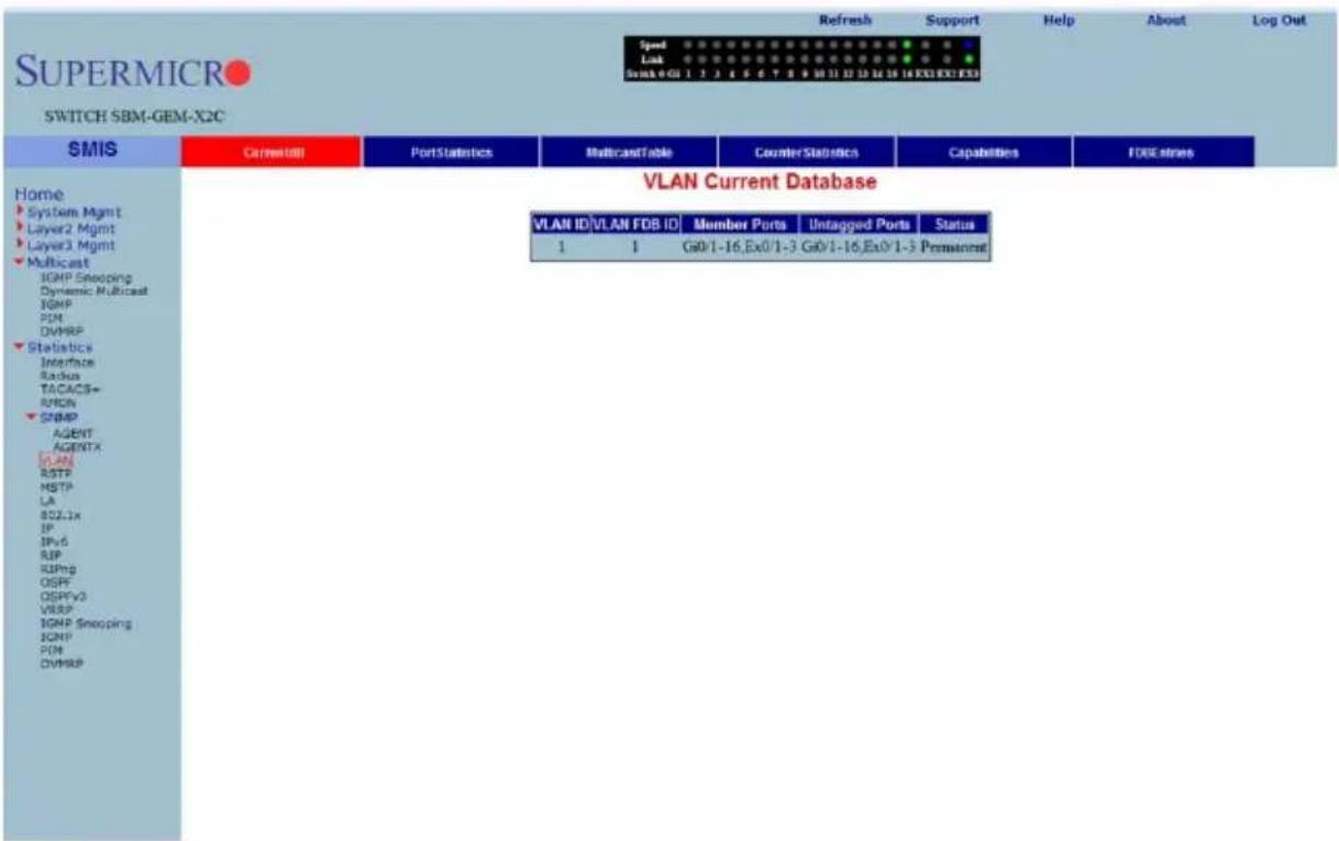
Clicking the CURRENT DB tab brings up the VLAN CURRENT DATABASE page (Figure 7-173), which displays VLAN database entries. The parameters for this page are shown in Table 7-142.
Table 7-142. VLAN Current Database Page Parameters
| Parameter Description | |
| VLAN ID This parameter specifies the VLAN identifier. | |
| VLAN FDB ID This parameter specifies the VLAN filter database identifier. | |
| Member Ports This parameter specifies the index of member ports. | |
| Untagged Ports This parameter specifies the index of untagged member ports. | |
| Status This parameter specifies the VALN status. | |
VLAN Port Statistics
Figure 7-174. VLAN Port Statistics Page
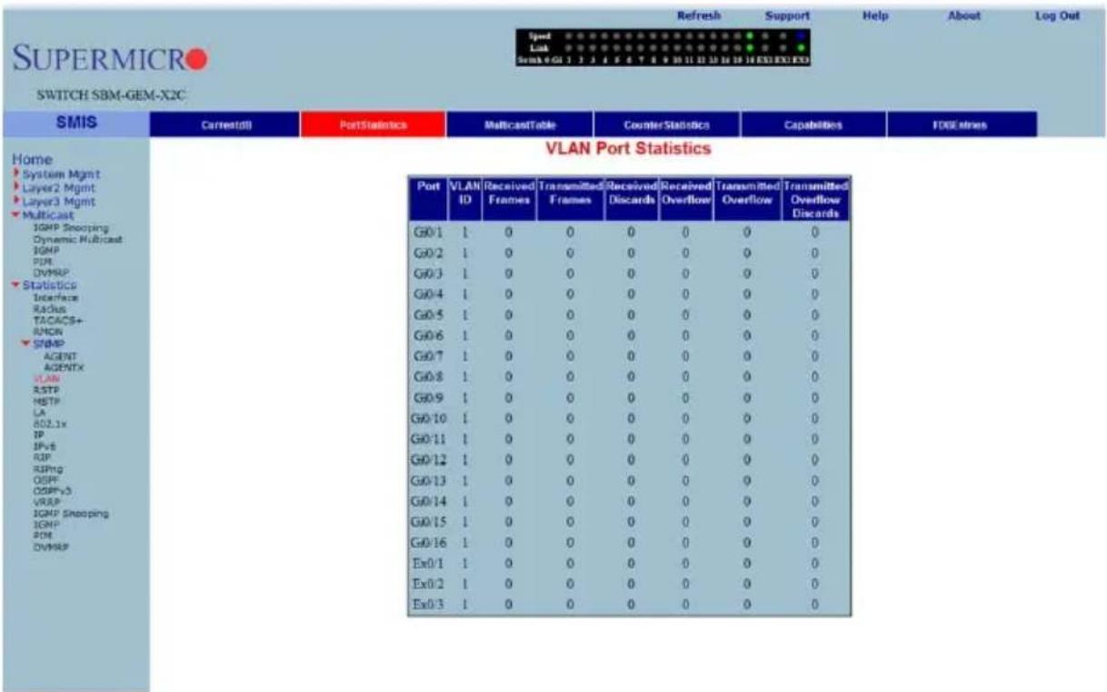
Clicking the PORT STATISTICS tab brings up the VLAN PORT STATISTICS page (Figure 7-174), which displays the various parameters XXXXXX. The parameters for this page are shown in Table 7-143.
Table 7-143. VLAN Port Statistics Page Parameters
| Parameter Description | |
| Port This parameter specifies the port index. | |
| VLAN ID This parameter specifies the VLAN identifier. | |
| Received Frames This parameter specifies the number of packets received in this VLAN. | |
| Transmitted Frames | This parameter specifies the number of packets transmitted in this VLAN. |
| Received Discards This parameter specifies the number of received packets discarded. | |
| Received Overflow This parameter specifies the number of received overflow packets. | |
| Transmitted Overflow This parameter specifies the number of transmit overflows. | |
| Transmitted Overflow Discards | This parameter specifies the number of transmit overflow discards. |
VLAN Multicast Table
Figure 7-175. VLAN Multicast Table Page
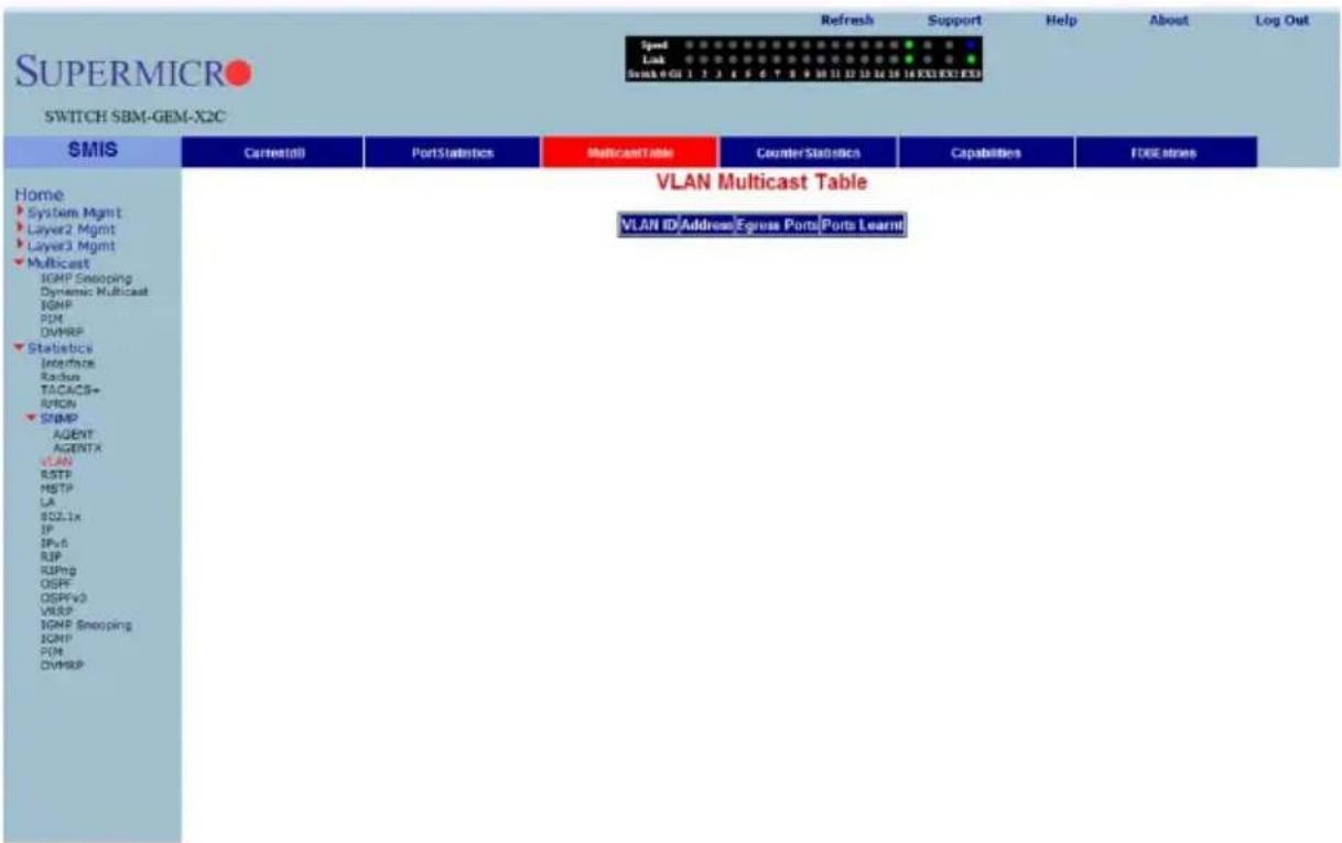
Clicking the MULTICAST TABLE tab brings up the VLAN MULTICAST TABLE page (Figure 7-175), which displays multicast VLAN information. The parameters for this page are shown in Table 7-144.
Table 7-144. VLAN Multicast Table Page Parameters
| Parameter Description | |
| VLAN ID This parameter specifies the VLAN identifier. | |
| Address This parameter specifies the VLAN address. | |
| Egress Ports This parameter specifies the indexes of egress ports. | |
| Ports Learnt | This parameter specifies the indexes of ports on this VLAN that are learned. |
VLAN Counter Statistics
Figure 7-176. VLAN Counter Statistics Page
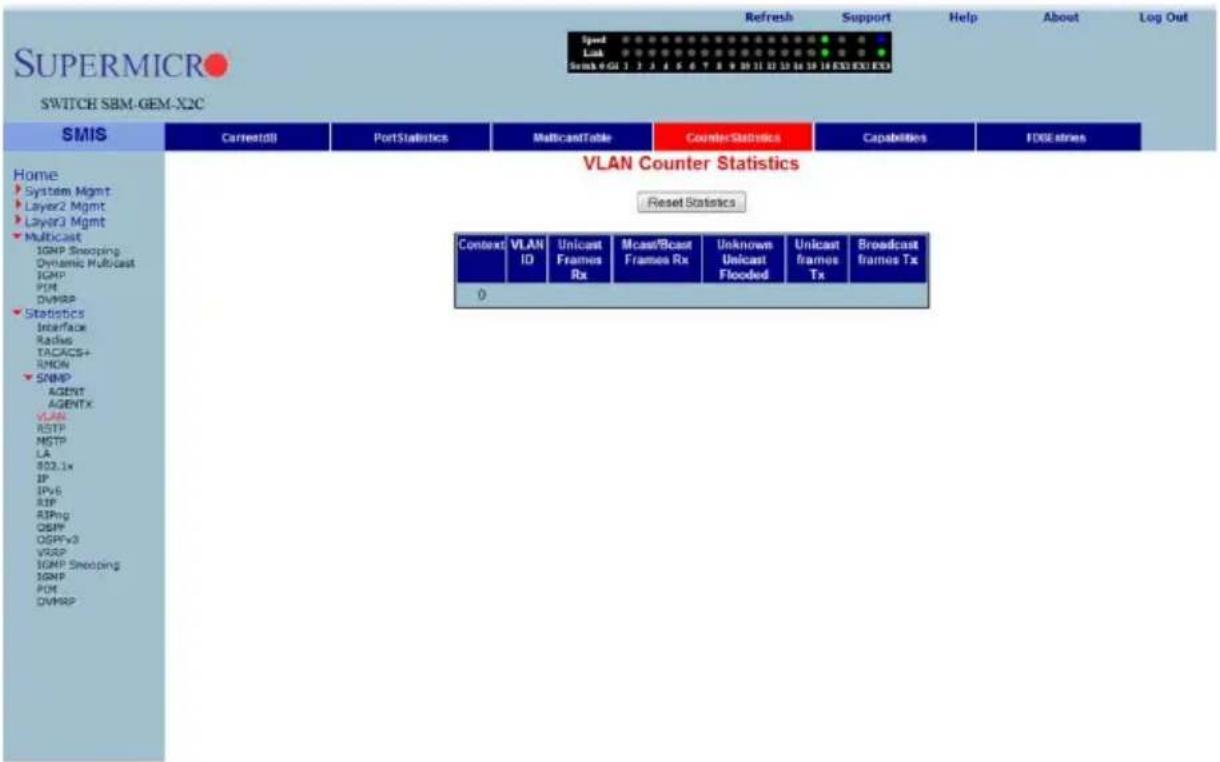
Clicking the COUNTER STATISTICS link brings up the VLAN COUNTER STATISTICS page (Figure 7-176), which displays VLAN counters. The parameters for this page are shown in Table 7-145.
Table 7-145. VLAN Counter Statistics Page Parameters
| Parameter Description | |
| VLAN ID This parameter specifies the VLAN identifier. | |
| Unicast Frames Rx This parameter specifies the number of unicast packets received. | |
| Mcast/Bcast Frames Rx This parameter specifies the number of non-unicast packets received. | |
| Unknown Unicast Flooded | This parameter specifies the number of packets flooded due to unknown unicast. |
| Unicast frames Tx This parameter specifies the number of unicast packets transmitted. | |
| Broadcast frames Tx | This parameter specifies the number of broadcast packets transmitted. |
VLAN Capabilities
Figure 7-177. VLAN Capabilities Page
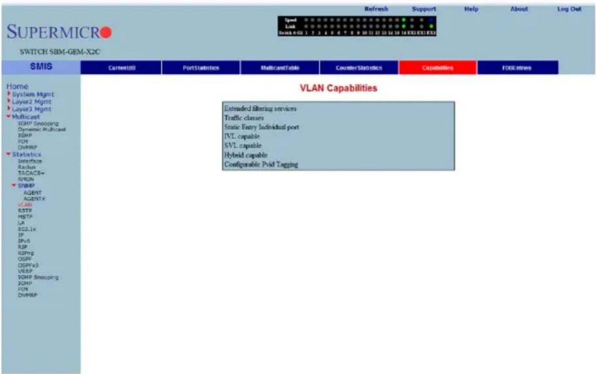
Clicking the CAPABILITIES tab brings up the VLAN CAPABILITIES page (Figure 7-177), which displays the VLAN capabilities of the switch. The parameters for this page are shown in Table 7-146.
Table 7-146. VLAN Capabilities Page Parameters
| Parameter Description | |
| Extended Filtering Services | This parameter specifies the number of extended filtering services. |
| Traffic Classes This parameter specifies the number of traffic classes | |
| Static Entry Individual port This parameter specifies the number of Static Entry Individual ports. | |
| IVL capable This parameter specifies the number of IVL capables. | |
| SVL capable This parameter specifies the number of SVL capables. | |
| Hybrid capable This parameter specifies the number of Hybrid capables. | |
| Configurable PVID Tagging This parameter specifies the number of Configurable PVID taggings. | |
VLAN FDB Entries
Figure 7-178. VLAN FDB Entries Page
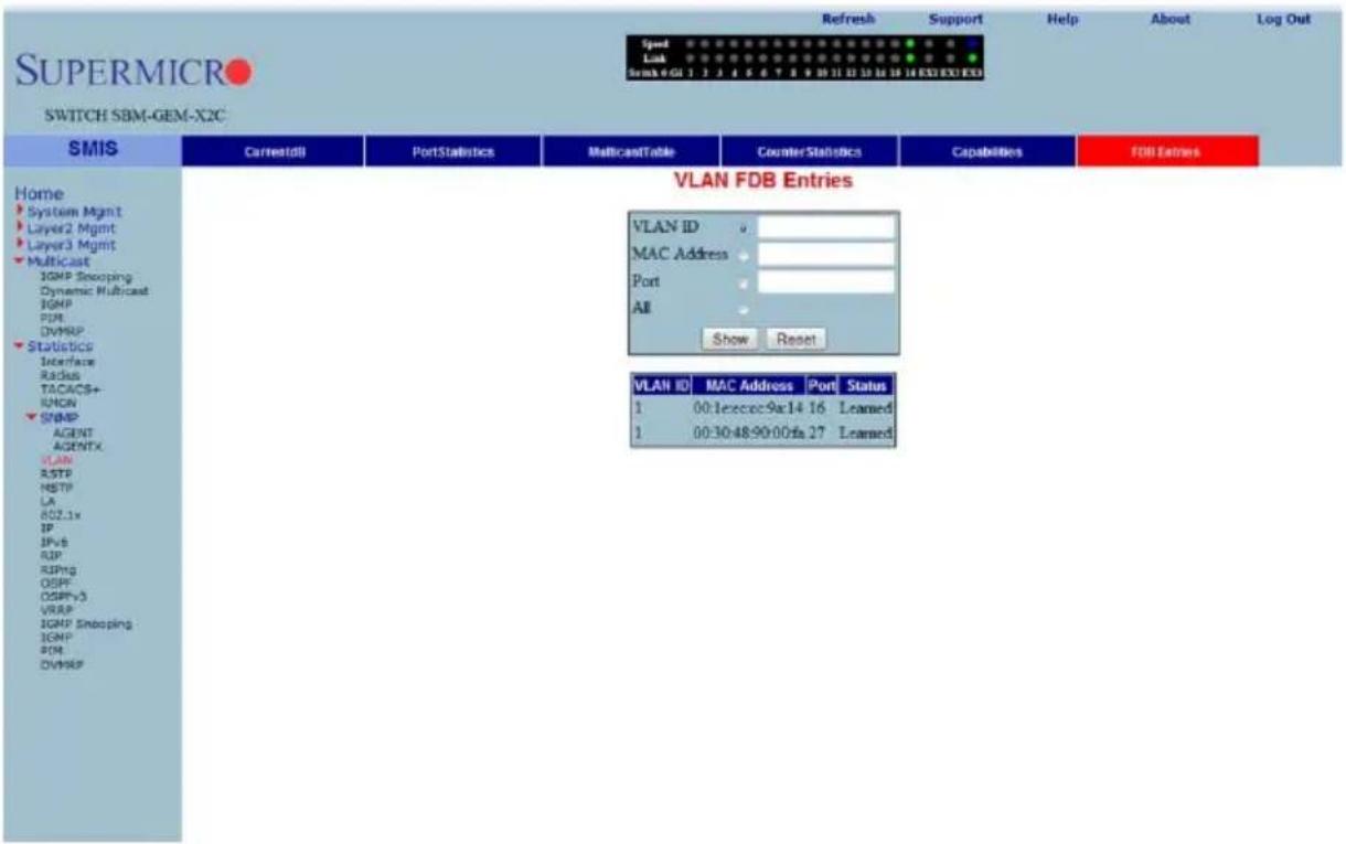
Clicking the FDB ENTRIES tab brings up the VLAN FDB ENTRIES page (Figure 7-178), which displays VLAN filter database entries. The parameters for this page are shown in Table 7-147.
Table 7-147. VLAN FDB Entries Page Parameters
| Parameter Description | |
| VLAN ID This parameter specifies the VLAN identifier. | |
| MAC Address This parameter specifies the MAC address learned. | |
| Port This parameter specifies the Index of port where this entry is learned. | |
| Status This parameter specifies the Status of this entry. | |
RSTP Statistics
The RSTP STATISTICS link allows you to view RSTP statistics through the following pages:
• "RSTP Information" on page 7-205
• "RSTP Port Statistics" on page 7-206
RSTP Information
Figure 7-179. RSTP Information Page
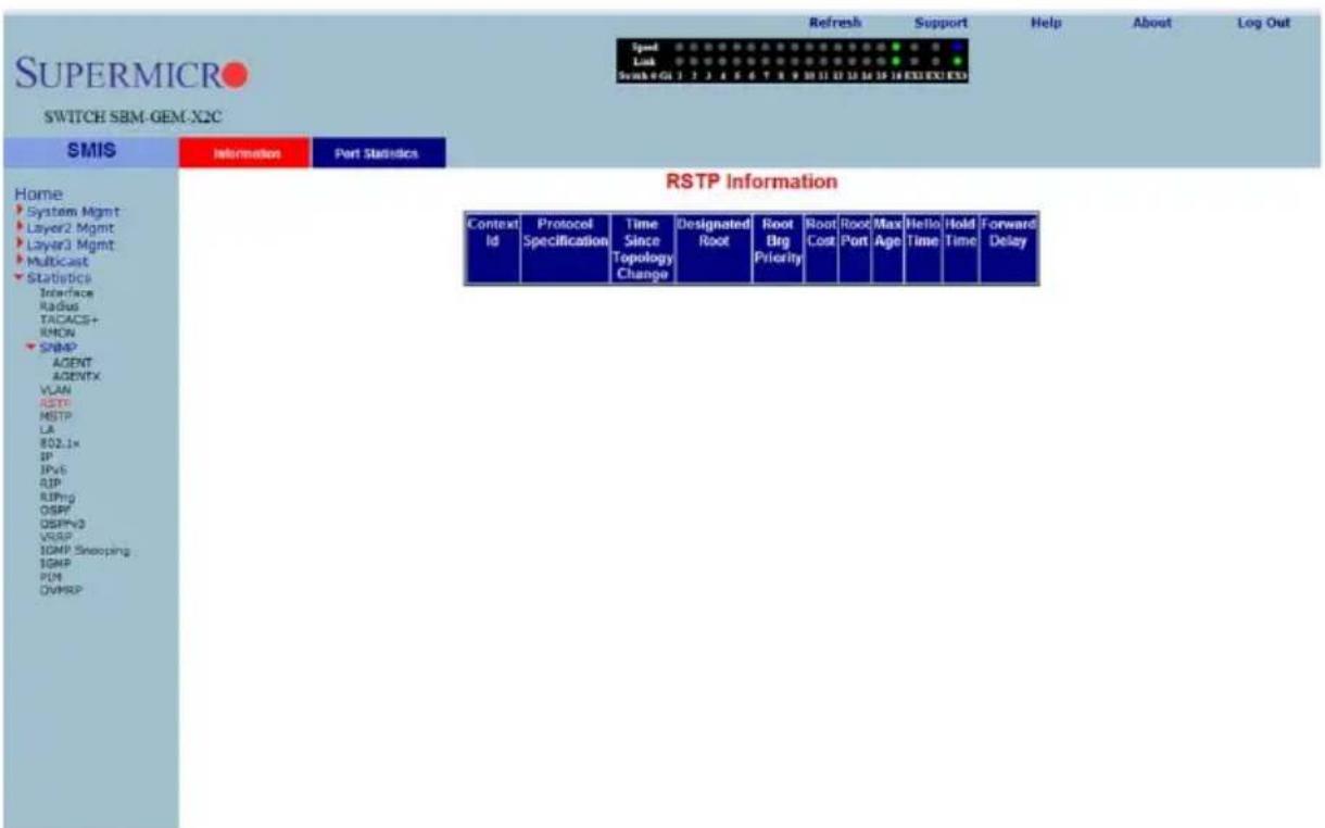
Clicking the INFORMATION tab brings up the RSTP INFORMATION page (Figure 7-179), which displays RSTP statistics. The parameters for this page are shown in Table 7-148.
Table 7-148. RSTP Information Page Parameters
| Parameter Description | |
| Protocol Specification This parameter specifies the Protocol Specification. | |
| Time Since Topology Change | This parameter specifies the number of seconds since topology changed. |
| Designated Root This parameter specifies the designated root bridge address. | |
| Root Brg Priority This parameter specifies the priority of root bridge. | |
| Root Cost This parameter specifies the cost to root. | |
| Root Port This parameter specifies the index of the root port. | |
| Max Age This parameter specifies the max age in seconds. | |
| Hello Time This parameter specifies the Hello time in seconds. | |
| Hold Time This parameter specifies the hold time in seconds. | |
| Forward Delay This parameter specifies the forward delay in seconds. | |
RSTP Port Statistics
Figure 7-180. RSTP Port Statistics Page
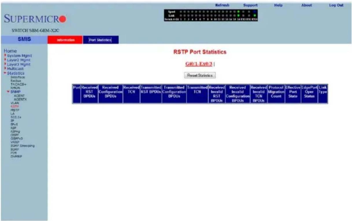
Clicking the PORT STATISTICS tab brings up the RSTP PORT STATISTICS page (Figure 7-180), which displays RSTP port level statistics. The parameters for this page are shown in Table 7-149.
Table 7-149. RSTP Port Statistics Page Parameters
| Parameter Description | |
| Port This parameter specifies the port index. | |
| Received RST BPDUs This parameter specifies the number of RSTP BPDUs received. | |
| Received Configuration BPDUs | This parameter specifies the number of config BPDUs received. |
| Received TCN | This parameter specifies the number of topology changed notifications received. |
| Transmitted RST BPDUs This parameter specifies the number of RSTP BPDUs transmitted. | |
| Transmitted Configuration BPDUs | This parameter specifies the number of config BPDUs transmitted. |
| Transmitted TCN | This parameter specifies the number of topology change notifications transmitted. |
| Received Invalid RST BPDUs | This parameter specifies the number of invalid RSTP BPDUs received. |
| Received Invalid Configuration BPDUs | This parameter specifies the number of invalid configuration BPDUs received. |
| Received Invalid TCN BPDUs | This parameter specifies the number of invalid topology change BPDUs received. |
| Protocol Migration Count | This parameter specifies the number of times protocol migration happened. |
| Effective Port State This parameter specifies the effective port state. | |
| EdgePort Oper Status This parameter specifies the operational status of edge port. | |
| Link Type This parameter specifies the broadcast or point-to-point. | |
MSTP Statistics
The MSTP Statistics link allows you to view MSTP statistics through the following pages:
• "MSTP Information" on page 7-208
• "MSTP CIST Statistics" on page 7-209
• "MSTP MSTI Port Statistics" on page 7-210
MSTP Information
Figure 7-181. MSTP Information Page
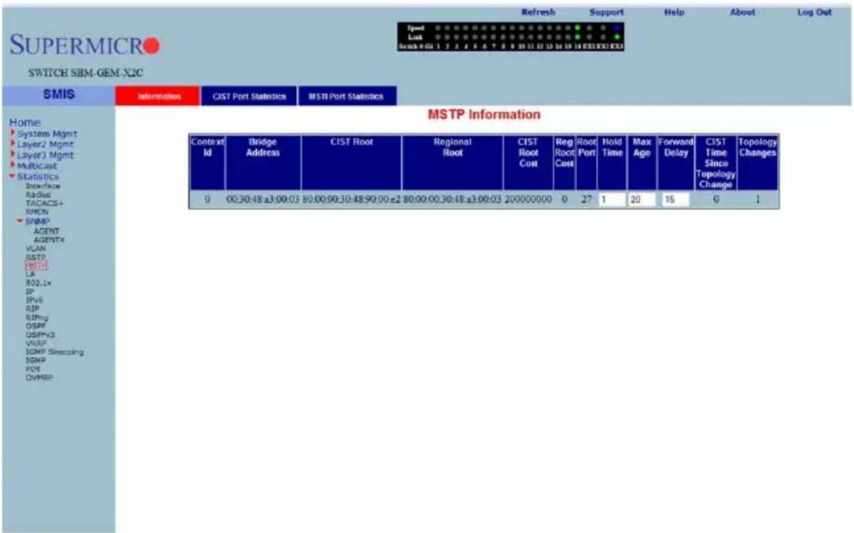
Clicking the INFORMATION tab brings up the MSTP INFORMATION page (Figure 7-137), which displays MSTP statistics. The parameters for this page are shown in Table 7-13.
Table 7-150. MSTP Information Page Parameters
| Parameter Description | |
| Bridge Address This parameter specifies the Bridge Address. | |
| CIST Root This parameter specifies the CIST root. | |
| Regional Root This parameter specifies the Regional root. | |
| CIST Root Cost This parameter specifies the CIST root cost. | |
| Regional Root Cost This parameter specifies the Regional root cost. | |
| Root Port This parameter specifies the index of the root port. | |
| Hold Time This parameter specifies the hold time in seconds. | |
| Max Age This parameter specifies the maximum age in seconds. | |
| Forward Delay This parameter specifies the forward delay in seconds. | |
| CIST Time Since Topology Change | This parameter specifies the number of seconds since topology last changed. |
| Topology Changes This parameter specifies the number of topology changes. | |
MSTP CIST Statistics
Figure 7-182. MSTP CIST Port Statistics Page
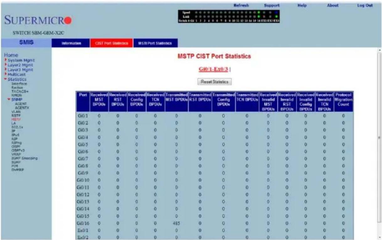
Clicking the CIST PORT STATISTICS tab brings up the MSTP CIST PORT STATISTICS page (Figure 7-182), which displays STP CIST port level statistics. The parameters for this page are shown in Table 7-151.
Table 7-151. MSTP CIST Port Statistics Page Parameters
| Parameter Description | |
| Received MST BPDUs This | parameter specifies the number of MSTP BPDUs received. |
| Received RST BPDUs This | parameter specifies the number of RSTP BPDUs received. |
| Received Config BPDUs This | parameter specifies the number of config BPDUs received. |
| Received TCN BPDUs | This parameter specifies the number of topology change notification BPDUs received. |
| Transmitted MST BPDUs This parameter specifies the number of MSTP BPDUs transmitted. | |
| Transmitted RST BPDUs This parameter specifies the number of RSTP BPDUs transmitted. | |
| Transmitted Config BPDUs This parameter specifies the number of config BPDUs transmitted. | |
| Transmitted TCN BPDUs | This parameter specifies the number of topology change notification BPDUs transmitted. |
| Received Invalid MST BPDUs | This parameter specifies the number of invalid MSTP BPDUs received. |
| Received Invalid RST BPDUs | This parameter specifies the number of invalid RSTP BPDUs received. |
| Received Invalid Config BPDUs | This parameter specifies the number of invalid config BPDUs received. |
| Received Invalid TCN BPDUs | This parameter specifies the number of invalid TCN BPDUs received. |
| Protocol Migration Count | This parameter specifies the number of times protocol migration happened. |
MSTP MSTI Port Statistics
Figure 7-183. MSTP MSTI Port Statistics Page
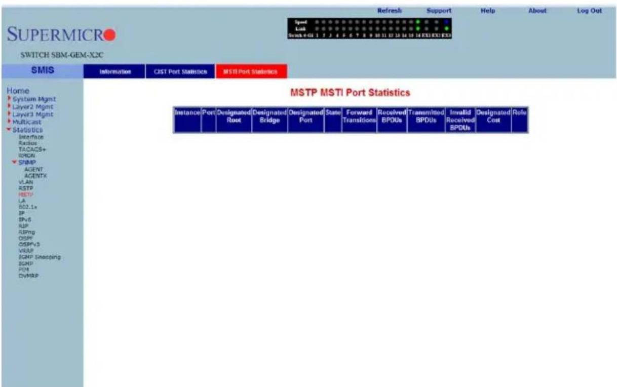
Clicking the MSTI PORT STATISTICS tab brings up the MSTP MSTI PORT STATISTICS page (Figure 7-183), which displays MSTP MSTI port level statistics. The parameters for this page are shown in Table 7-152.
Table 7-152. MSTP MSTI Port Statistics Page Parameters
| Parameter Description | |
| Instance This parameter specifies the MSTP instance Identifier. | |
| Port This parameter specifies the port index. | |
| Designated Root This parameter specifies the designated root bridge address. | |
| Designated Bridge This parameter specifies the designated Bridge address. | |
| Designated Port | This parameter specifies the index of designated port for this MSTP instance. |
| State This parameter specifies the current state. | |
| Forward Transitions This parameter specifies the number of Forward Transitions. | |
| Received BPDUs This parameter specifies the number of BPDUs received. | |
| Transmitted BPDUs This parameter specifies the number of BPDUs transmitted. | |
| Invalid Received BPDUs | This parameter specifies the number of invalid BPDUs received. |
| Designated Cost This parameter specifies the designated cost. | |
| Role This parameter specifies the current role. | |
The Link Aggregation link allows you to view Link Aggregation (LA) statistics through the following pages:
• "LA Port Statistics" on page 7-212
• "LA Neighbor Statistics" on page 7-213
LA Port Statistics
Figure 7-184. LA Port Statistics Page
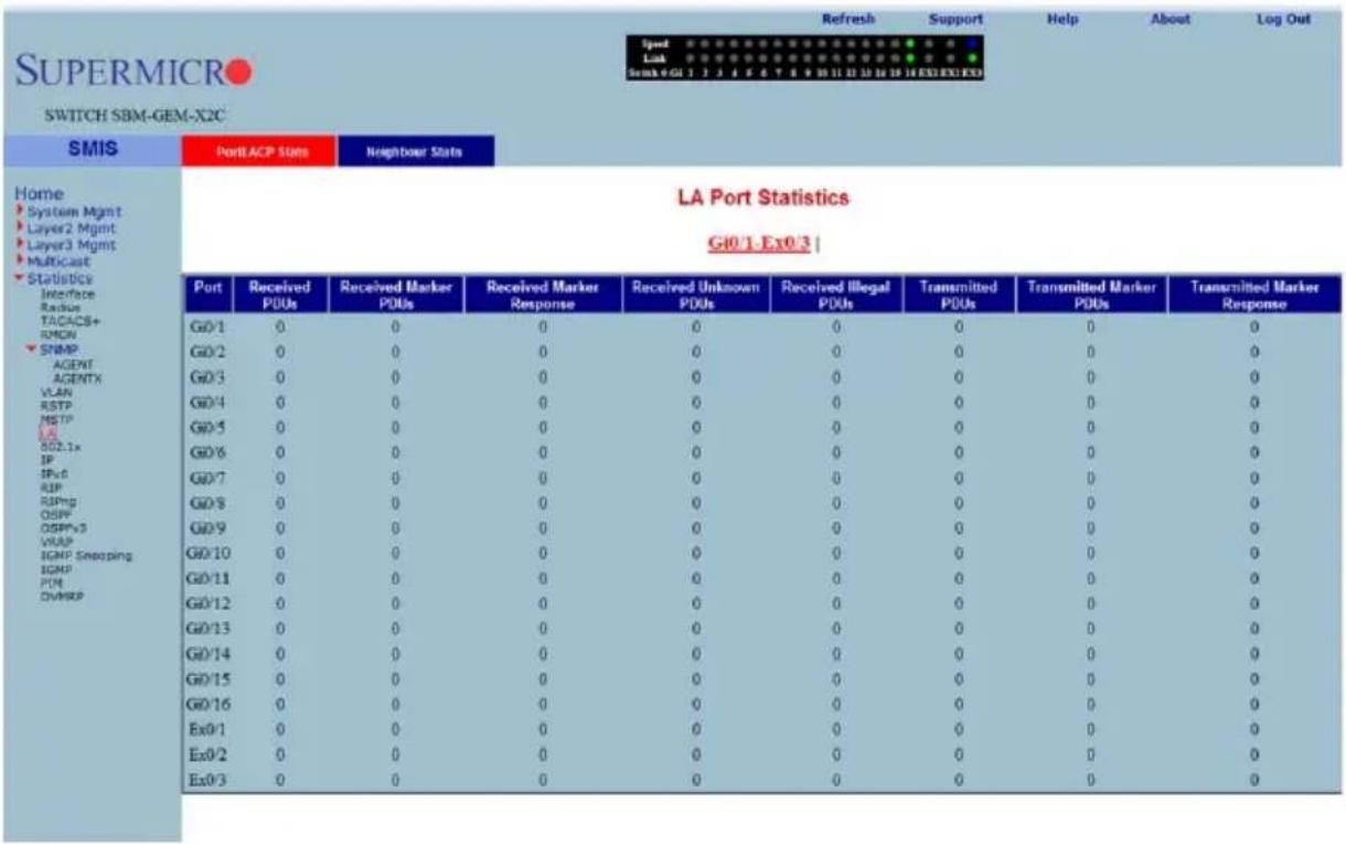
Clicking the PORT LACP STATS tab brings up the LA PORT STATISTICS page (Figure 7-184), which displays LACP port level statistics. The parameters for this page are shown in Table 7-153.
Table 7-153. LA Port Statistics Page Parameters
| Parameter Description | |
| Port This parameter specifies the port index. | |
| Received PDUs This parameter specifies the number of LACP PDUs received. | |
| Received Marker PDUs This parameter specifies the number of Marker PDUs received. | |
| Received Marker Response This parameter specifies the number of Marker response PDUs received. | |
| Received Unknown PDUs This parameter specifies the number of unknown PDUs received. | |
| Received Illegal PDUs This parameter specifies the number of invalid PDUs received. | |
| Transmitted PDUs This parameter specifies the number of LACP PDUs transmitted. | |
| Transmitted Marker PDUs This parameter specifies the number of Marker PDUs transmitted. | |
| Transmitted Marker Response This parameter specifies the number of Marker response PDUs transmitted. | |
LA Neighbor Statistics
Figure 7-185. LA Neighbor Statistics Information Page
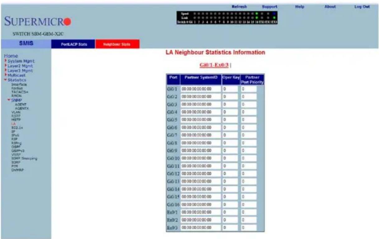
Clicking the NEIGHBOR STATS tab brings up the LA NEIGHBOR STATISTICS INFORMATION page (Figure 7-185), which displays LACP neighbor statistics. The parameters for this page are shown in Table 7-154.
Table 7-154. LA Neighbor Statistics Information Page Parameters
| Parameter Description | |
| Port Index This parameter specifies the port index. | |
| Partner SystemID This parameter specifies the Partner SystemID. | |
| Oper Key This parameter specifies the Oper Key. | |
| Partner Port Priority This parameter specifies the Partner Port Priority. | |
802.1X
The 802.1x link allows you to view 802.1x statistics through the following pages:
• "802.1X Session Statistics" on page 7-214
- "802.1X Supplicant Statistics" on page 7-215
• "Mac Session Statistics" on page 7-216
802.1X Session Statistics
Figure 7-186. 802.1x Session Statistics Page
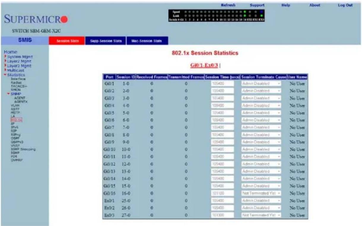
Clicking the SESSION STATS tab brings up the 802.1x SESSION STATISTICS page (Figure 7-186), which displays 802.1x statistics information. The parameters for this page are shown in Table 7-155.
Table 7-155. 802.1x Session Statistics Page Parameters
| Parameter Description | |
| Port This parameter specifies the port index. | |
| Session ID This parameter specifies the session identifier. | |
| Received Frames This parameter specifies the number of packets received. | |
| Transmitted Frames This parameter specifies the number of packets transmitted. | |
| Session Time (secs) This parameter specifies the session time in seconds. | |
| Parameter DescriptionSession Terminate Cause This parameter specifies the reason for session termination. | |
| User Name This parameter specifies the name of the user authenticated. | |
802.1X Supplicant Statistics
Figure 7-187. 802.1x Supplicant Session Statistics Page
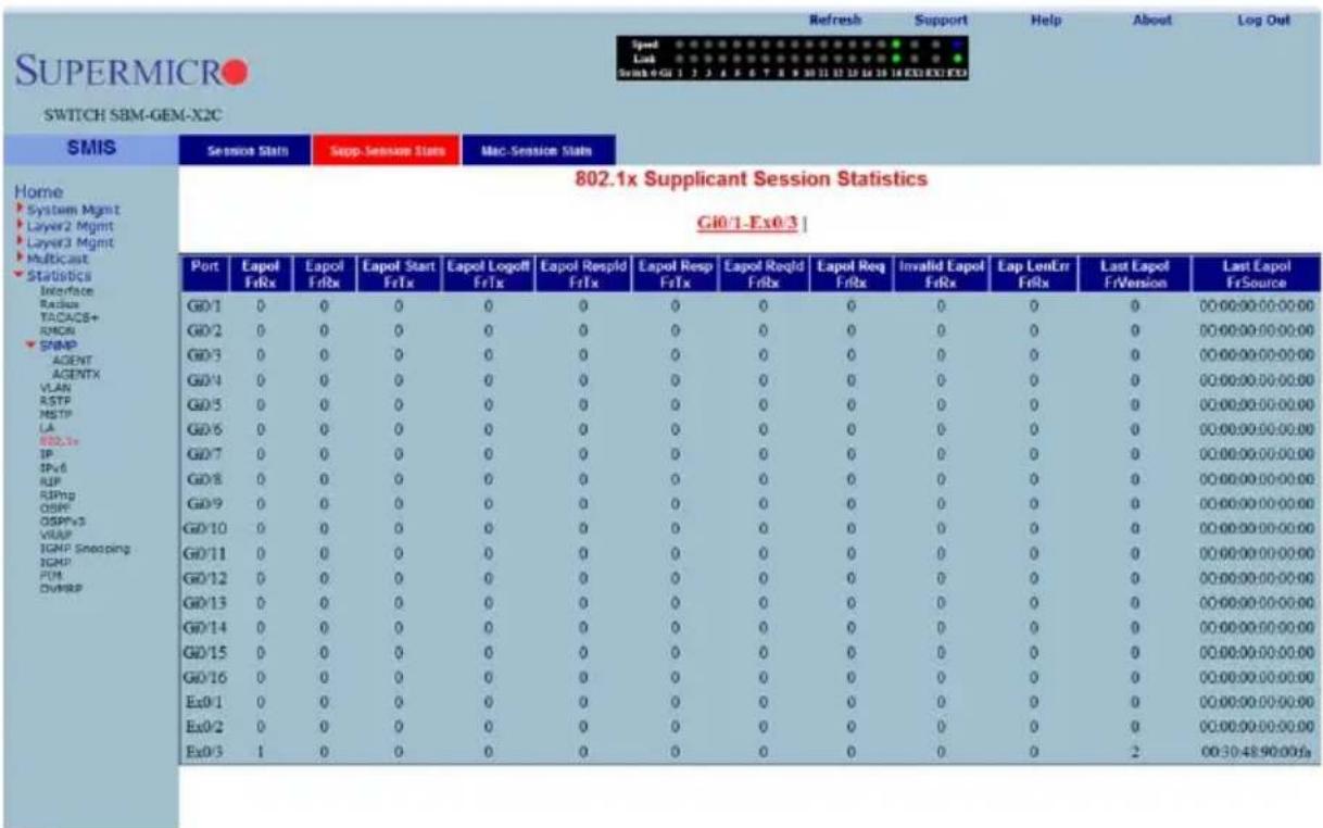
Clicking the SUPP SESSION STATS tab brings up the 802.1x SUPPLICANT SESSION STATISTICS page (Figure 7-187), which displays information about the 802.1x supplicant session. The parameters for this page are shown in Table 7-156.
Table 7-156. 802.1x Supplicant Session Statistics Page Parameters
| Parameter Description | |
| Port This parameter specifies the port index. | |
| Eapol FrRx This parameter specifies the number of the EAPOL packets received. | |
| Eapol FrTx This parameter specifies the number of the EAPOL packets transmitted. | |
| Eapol Start FrTx | This parameter specifies the number of the EAPOL start packet transmitted. |
| Eapol Logoff FrTx | This parameter specifies the number of the EAPOL logoff packet transmitted. |
| Eapol Respld FrTx | This parameter specifies the number of the EAPOL response identifier packet transmitted. |
| Eapol Resp FrTx | This parameter specifies the number of the EAPOL response packet frame transmitted. |
| Eapol ReqId FrRx | This parameter specifies the number of the EAPOL request identifier packet received. |
| Eapol Req FrRx | This parameter specifies the number of the EAPOL request frame received. |
| Invalid Eapol FrRx | This parameter specifies the number of the invalid EAPOL frame received. |
| Eap LenErr FrRx | This parameter specifies the number of EAPOL packets received with an invalid length. |
| Last Eapol FrVersion This parameter specifies the version on the last EAPOL packet. | |
| Last Eapol FrSource This parameter specifies the source of the last EAPOL packet. | |
Mac Session Statistics
Figure 7-188. MAC Session Statistics Page
![SUPERMICRO SWITCH SBM-GEM-X2C SMIS Service Stats Step-Session Stats Mac-Session Stats Home System Mgmt Layer2 Mgmt Layer3 Mgmt Multicast Statistics Interface Radius TACACS+ RMGN SNMP AGENT AGENTX VLAN RSTP MSTP LA SCL1+ IP IPx5 RUP RIPing OSPF OSPFx5 VRAP IGMP Snooping IGMP FIM DVMRP MAC Session Statistics Supplicant MacAddr Submit Select[Supplicant MacAddr]Frames Rx |Frames Tx |Session ID |Session Terminto Cause |User Name](/content/2026/05/1141607/images/3cfe274738aea12e32699ddf59db09593d8210794c28fa73a1893003456dbc23.jpg)
Clicking the MAC SESSION STATS tab brings up the MAC SESSION STATISTICS page (Figure 7-188), which displays statistics information about 802.1x MAC sessions. The parameters for this page are shown in Table 7-157.
Table 7-157. MAC Session Statistics Page Parameters
| Parameter Description | |
| Supplicant MacAddr This parameter specifies the supplicant MAC address. | |
| Frames Rx This parameter specifies the number of packets received. | |
| Frames Tx This parameter specifies the number of packets transmitted. | |
| Session ID This parameter specifies the session identifier. | |
| Session Terminte Cause This parameter specifies the reason for session termination. | |
| User Name This parameter specifies the name of user authenticated. | |
IP
The IP link allows you to view IP statistics through the following pages:
- "ARP Cache" on page 7-218
• "ICMP Statistics" on page 7-219
ARP Cache
Figure 7-189. ARP Cache Page
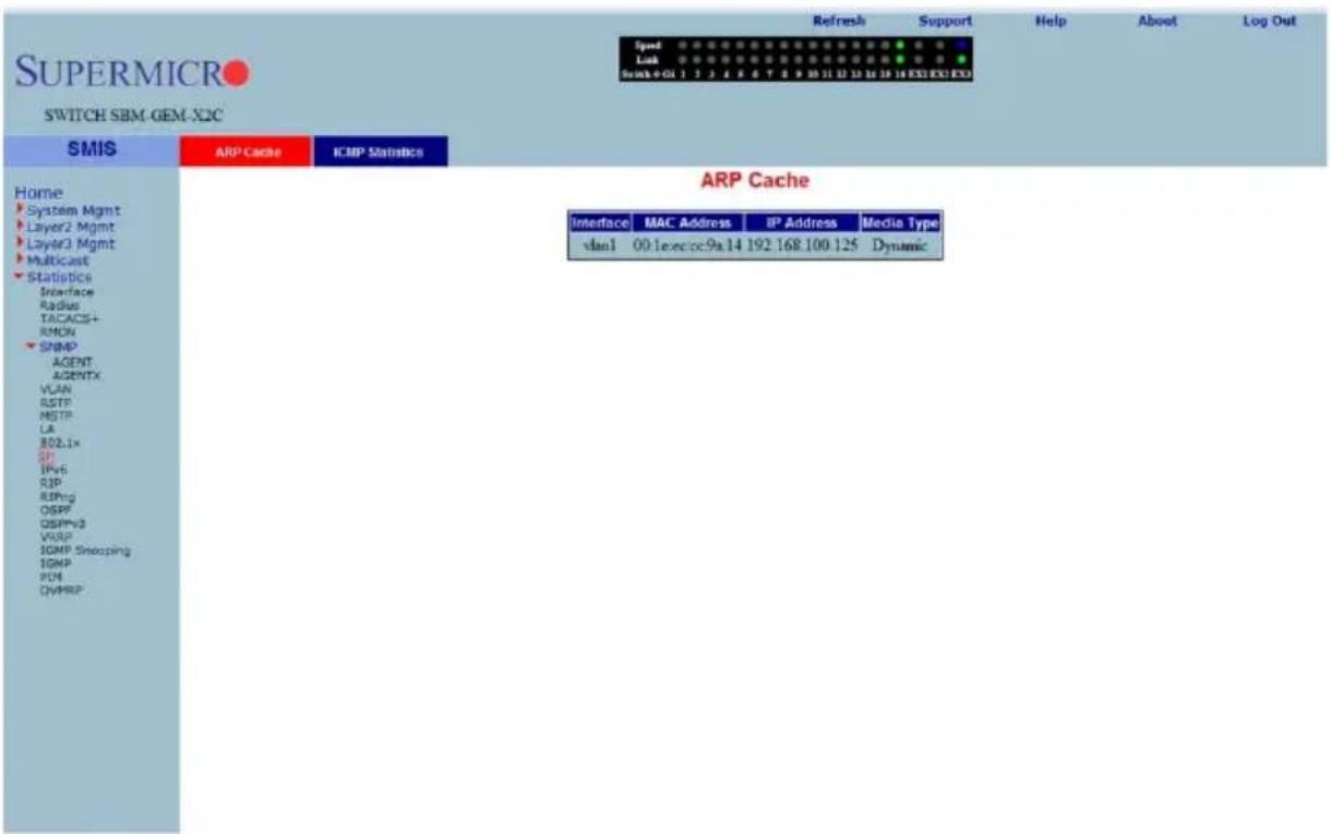
Clicking the ARP CACHE tab brings up the ARP CACHE page (Figure 7-189), which displays ARP entries. The parameters for this page are shown in Table 7-158.
Table 7-158. ARP Cache Page Parameters
| Parameter Description | |
| Interface | This parameter specifies the interface from which this ARP entry is learned. |
| MAC Address This parameter specifies the MAC address. | |
| IP Address This parameter specifies the IP address. | |
| Media Type This parameter specifies the static ARP or dynamic ARP. | |
ICMP Statistics
Figure 7-190. ICMP Statistics Page
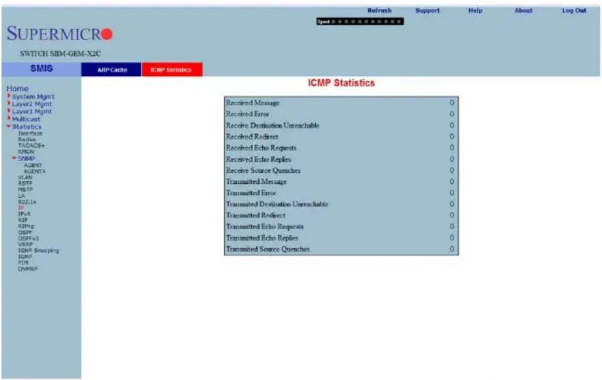
Clicking the ICMP STATISTICS tab brings up the ICMP STATISTICS page (Figure 7-190), which displays ICMP statistics information. The parameters for this page are shown in Table 7-159.
Table 7-159. ICMP Statistics Page Parameters
| Parameter Description | |
| Received Message This parameter specifies the number of received messages. | |
| Received Error This parameter specifies the number of received errors. | |
| Receive Destination Unreachable | This parameter specifies the number of received destination unreachable. |
| Received Redirect This parameter specifies the number of received redirects. | |
| Received Echo Requests This parameter specifies the number of echo requests.. | |
| Received Echo Replies This parameter specifies the number of echo replies. | |
| Receive Source Quenches This parameter specifies the number of source quenches. | |
| Transmitted Message This parameter specifies the number of transmitted messages. | |
| Transmitted Error This parameter specifies the number of transmitted errors. | |
| Transmitted Destination Unreachable | This parameter specifies the number of transmitted destination unreachable. |
| Transmitted Redirect This parameter specifies the number of transmitted redirects. | |
| Transmitted Echo Requests | This parameter specifies the number of transmitted echo requests. |
| Transmitted Echo Replies | This parameter specifies the number of transmitted echo replies. |
| Transmitted Source Quenches | This parameter specifies the number of transmitted source quenches. |
IPv6
The IPv6 link allows you to view IPv6 statistics through the following pages:
- "IP V6 Interface Statistics" on page 7-221
• "ICMP V6 Statistics" on page 7-223
IP V6 Interface Statistics
Figure 7-191. IPV6 Interface Statistics Page
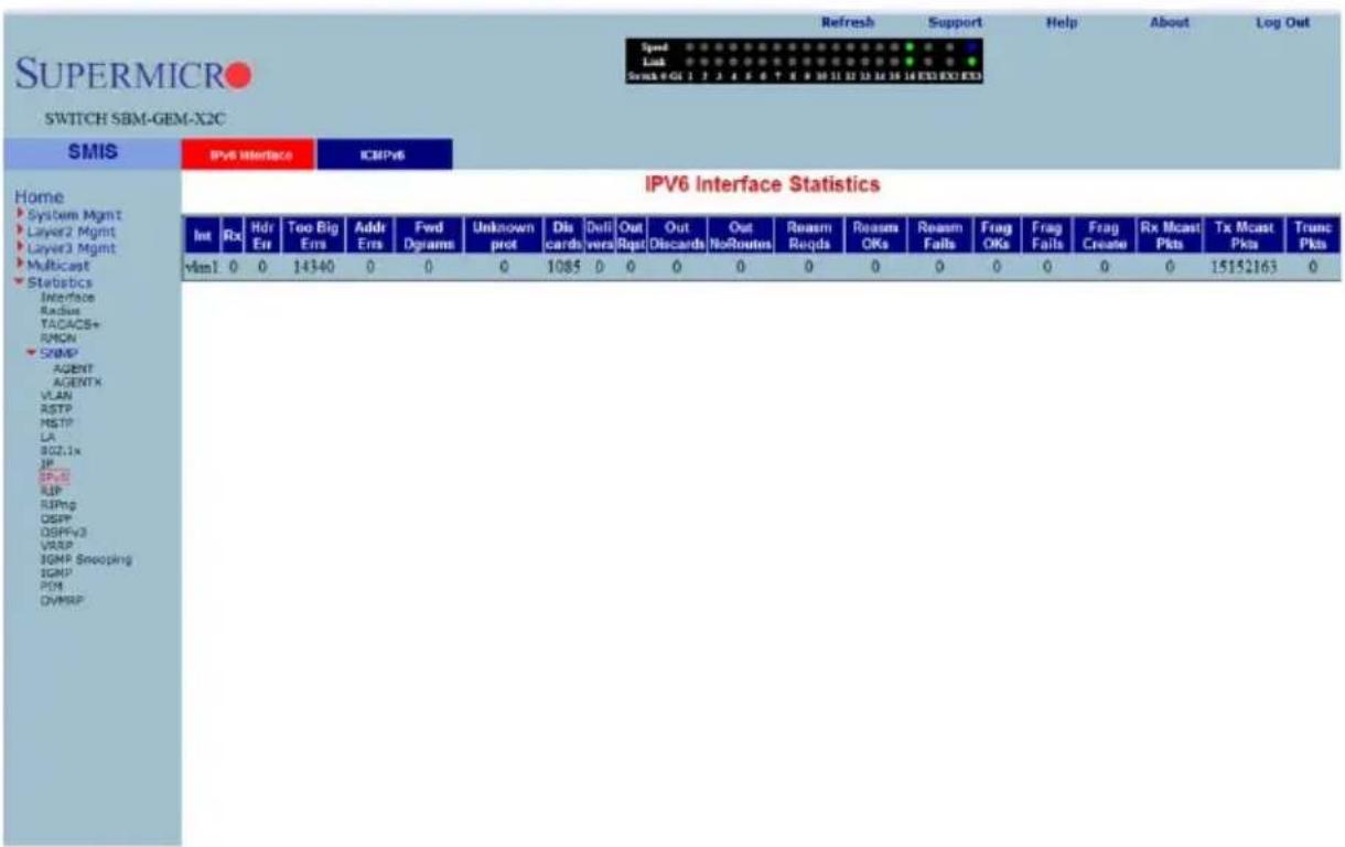
Clicking the IPV6 INTERFACE tab brings up the IPV6 INTERFACE STATISTICS page (Figure 7-191), which displays IPv6 port statistics. The parameters for this page are shown in Table 7-160.
Table 7-160. IPV6 Interface Statistics Page Parameters
| Parameter Description | |
| Interface This parameter specifies the Port index. | |
| Rcvd This parameter specifies the number of IPv6 packets received. | |
| Hdr Err | This parameter specifies the number of IPv6 packets received with header error. |
| Too Big Errs This parameter specifies the number of too big IPv6 packets received. | |
| Addr Errs | This parameter specifies the number of IPv6 packets received with address errors. |
| Parameter DescriptionFwd Dgrams | This parameter specifies the number of IPv6 datagrams forwarded in this port. |
| Unknown protos | This parameter specifies the number of packets received with unknown protocol. |
| Discdrs | This parameter specifies the number of received packets discarded due to errors. |
| Delivers This parameter specifies the number of packets delivered. | |
| Out Rqst This parameter specifies the number of transmit requests. | |
| Out Discards This parameter specifies the number of transmit discards due to errors. | |
| Out No Routes | This parameter specifies the number of packets to be transmitted but no routes. |
| Reasm Reqds This parameter specifies the number of reassembly requests. | |
| Reasm OKs This parameter specifies the number or successful reassemblies. | |
| Reasm Fails This parameter specifies the number of reassemblies failed. | |
| Frag OKs This parameter specifies the number of good fragments received. | |
| Frag Fails This parameter specifies the number of fragments incompletely received. | |
| Frag Creates This parameter specifies the number of fragments created. | |
| Rcvd Mcast Pkts This parameter specifies the number of received IPv6 multicast packets. | |
| Send Mcast Pkts | This parameter specifies the number of IPv6 multicast packets transmitted. |
| Trunctd Pkts This parameter specifies the number of packets truncated. | |
ICMP V6 Statistics
Figure 7-192. ICMPv6 Statistics Page
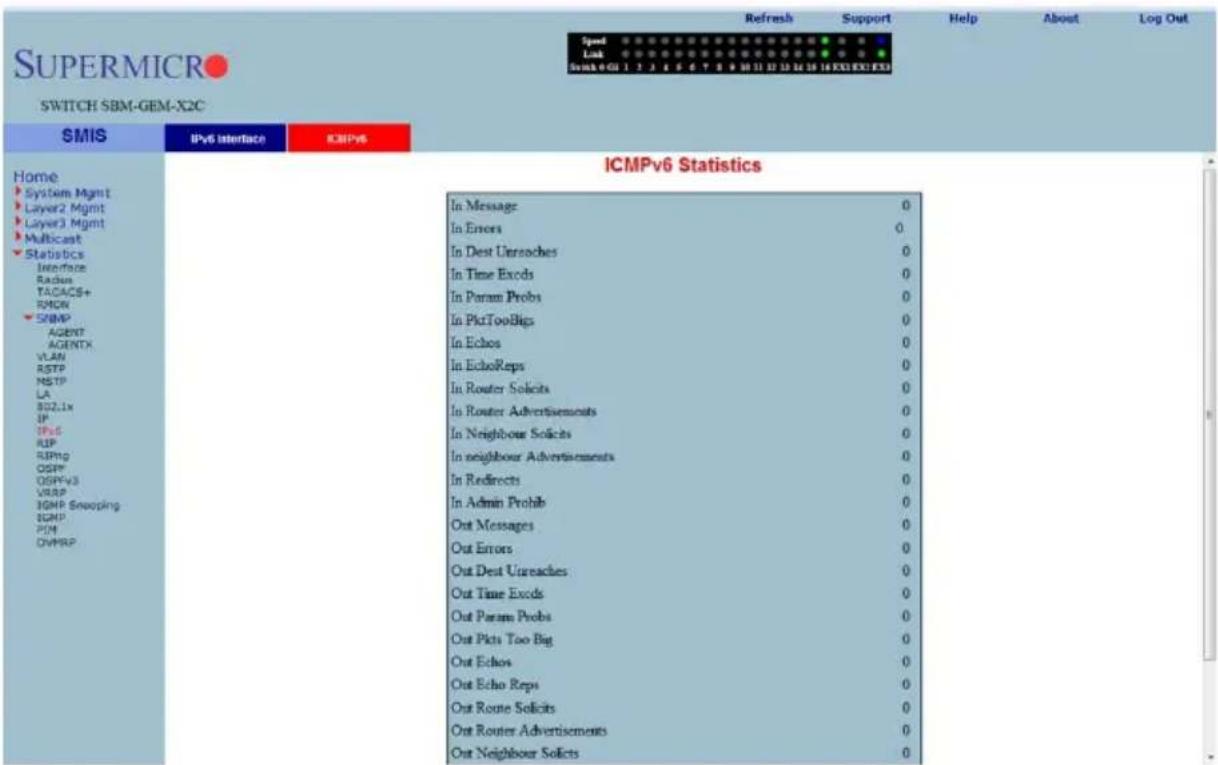
Clicking the ICMPv6 tab brings up the ICMPv6 STATISTICS page (Figure 7-192), which displays ICMPv6 statistics. The parameters for this page are shown in Table 7-161.
Table 7-161. ICMPv6 Statistics Page Parameters
| Parameter Description | |
| In Message This parameter specifies the number of messages received. | |
| In Errors | This parameter specifies the number of messages received with errors. |
| In Dest Unreaches | This parameter specifies the number of destination unreachable messages received. |
| In Time Excds This parameter specifies the number of receive timeouts. | |
| In Param Probs This parameter specifies the number of parameters probed. | |
| In PktTooBigs This parameter specifies the number of too big packets received. | |
| In Echos This parameter specifies the number of echo requests received. | |
| In EchoReps | This parameter specifies the number of echo responses received. |
| In Router Solicits This parameter specifies the number of received router solicits. | |
| In Router Advertisements | This parameter specifies the number of routers advertisement received. |
| In Neighbor Solicits This parameter specifies the number of received neighbor solicits. | |
| In Neighbor Advertisements | This parameter specifies the number of received neighbor solicits. |
| In Redirects This parameter specifies the number of redirect packets received. | |
| In Admin Prohib This parameter specifies the number of receive admin prohibited. | |
| Out Messages This parameter specifies the number of messages transmitted. | |
| Out Errors | This parameter specifies the number of messages transmitted with errors. |
| Out Dest Unreaches | This parameter specifies the number of destination unreachable messages transmitted. |
| Out Time Excds This parameter specifies the number of transmit timeouts. | |
| Out Param Probs This parameter specifies the number of parameters probed. | |
| Out Pkts Too Big This parameter specifies the number of too big packets transmitted. | |
| Out Echos This parameter specifies the number of echo requests transmitted. | |
| Out Echo Reps | This parameter specifies the number of echo responses transmitted. |
| Out Route Solicits This parameter specifies the number of transmitted router solicits. | |
| Out Router Advertisements | This parameter specifies the number of transmitted neighbor solicits. |
| Out Neighbour Solicts | This parameter specifies the number of transmitted neighbor solicits. |
| Out Neighbour Advertisements | This parameter specifies the number of transmitted neighbor solicits. |
| Out Redirects This parameter specifies the number of redirect packets transmitted. | |
| Out Admin Prohib This parameter specifies the number of transmit admin prohibited. | |
| In Bad Code This parameter specifies the number of bad code packets. | |
RIP Statistics
Figure 7-193. RIP Interface Statistics Page
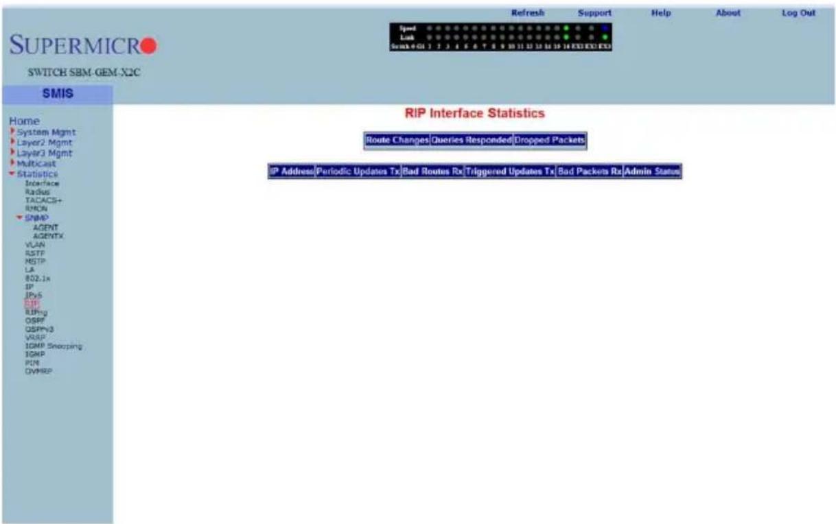
Clicking the RIP link brings up the RIP INTERFACE STATISTICS page (Figure 7-193), which displays RIP statistics. The parameters for this page are shown in Table 7-162.
Table 7-162. RIP Interface Statistics Page Parameters
| Parameter Description | |
| IP Address This parameter specifies the IP address. | |
| Received Bad Packets This parameter specifies the number of received bad packets. | |
| Received Bad Routes This parameter specifies the number of received bad routes. | |
| Transmitted Updates This parameter specifies the the number of transmitted updates. | |
RIP6
The RIP6 link allows you to view RIP6 statistics through the following pages:
• "RIP6 Interface Statistics" on page 7-226
• "RIP6 Route Information" on page 7-227
RIP6 Interface Statistics
Figure 7-194. RIP6 Interface Statistics Page
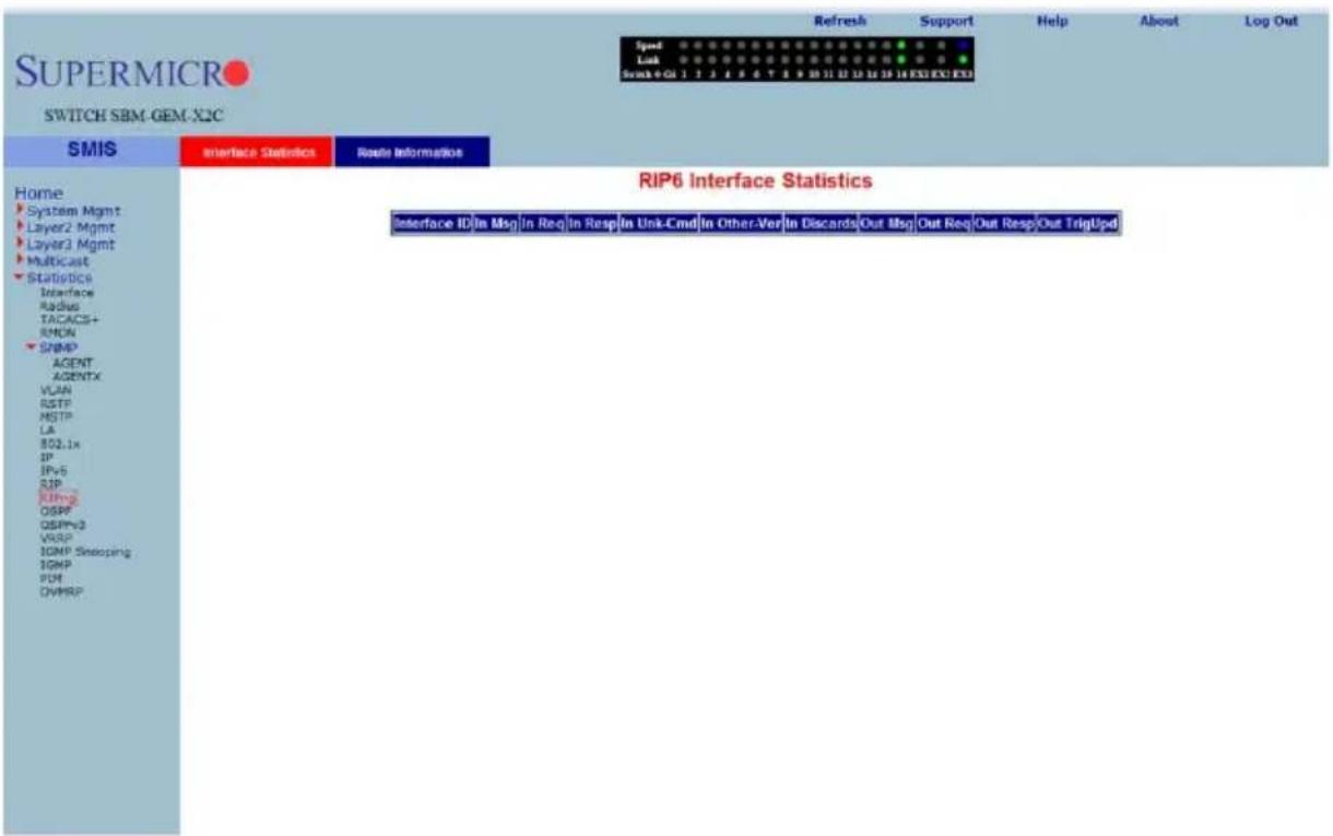
Clicking the INTERFACE STATISTICS tab brings up the RIP6 INTERFACE STATISTICS page (Figure 7-194), which displays RIPng statistics. The parameters for this page are shown in Table 7-163.
Table 7-163. RIP6 Interface Statistics Page Parameters
| Parameter Description | |
| Interface ID This parameter specifies the interface identifier. | |
| In Msg This parameter specifies the number of RIPng packets received. | |
| In Req This parameter specifies the number of RIPng request packets received. | |
| In Resp This parameter specifies the number of RIPng response packets received. | |
| In Unk-Cmd | This parameter specifies the number of RIPng unknown command packets received. |
| In Other-Ver | This parameter specifies the number of RIPng other version packets received. |
| In Discards This parameter specifies the number of received packets discarded. | |
| Out Msg This parameter specifies the number of RIPng packets transmitted. | |
| Out Req | This parameter specifies the number of RIPng request packets transmitted. |
| Out Resp | This parameter specifies the number of RIPng response packets transmitted. |
| Out TrigUpd | This parameter specifies the number of RIPng triggered updates transmitted. |
RIP6 Route Information
Figure 7-195. RIP6 Route Information Page
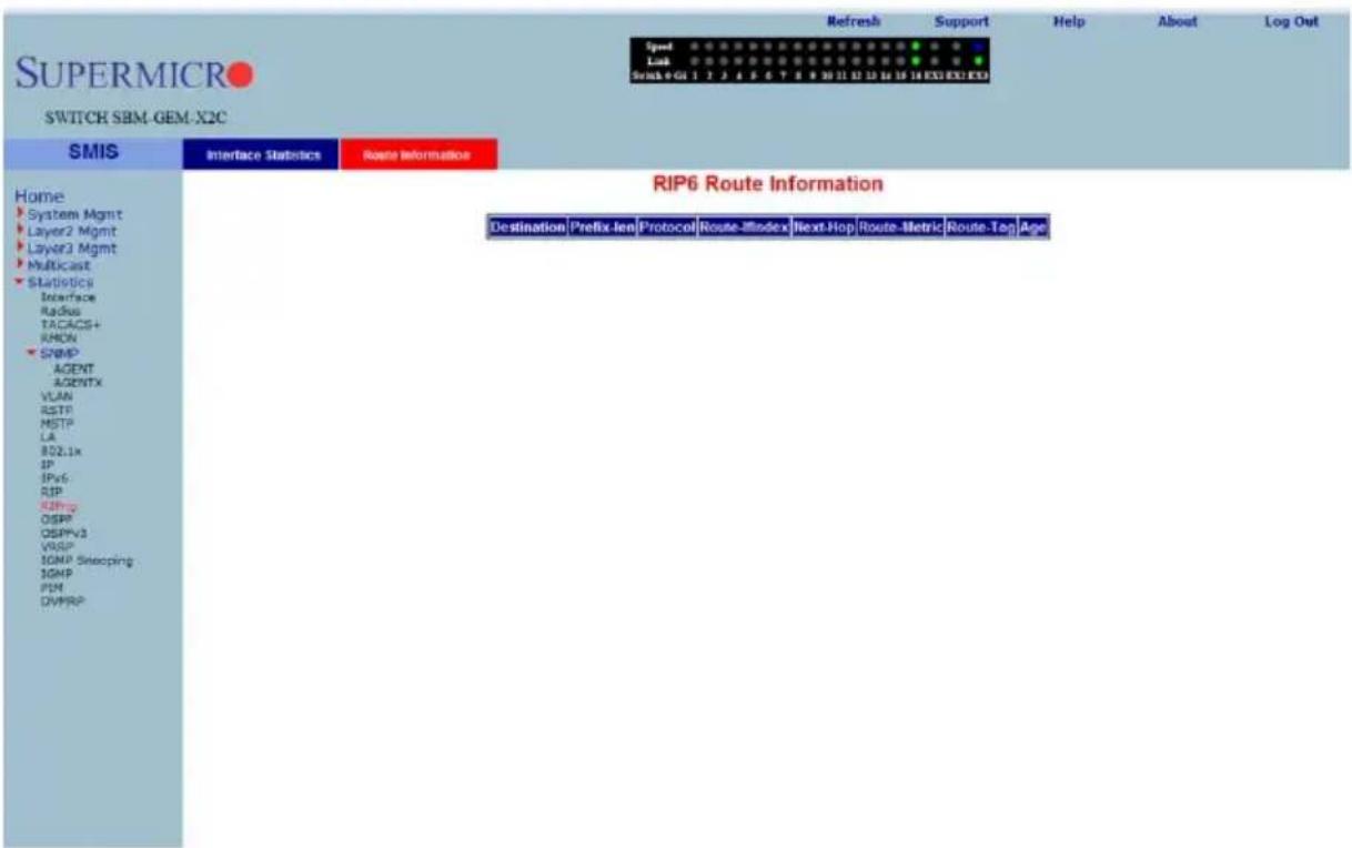
Clicking the ROUTE INFORMATION tab brings up the RIP6 ROUTE INFORMATION page (Figure 7-195), which displays information about RIPng routes. The parameters for this page are shown in Table 7-164.
Table 7-164. RIP6 Route Information Page Parameters
| Parameter Description | |
| Destination This parameter specifies the route destination. | |
| Prefix-len This parameter specifies the length of the route prefix. | |
| Protocol This parameter specifies the routing protocol | |
| Route-IfIndex This parameter specifies the interface index. | |
| Next-Hop This parameter specifies the next hop for this route. | |
| Route-Metric This parameter specifies the metric of this route. | |
| Route-Tag This parameter specifies the route tag identifier. | |
| Age This parameter specifies the route age in seconds. | |
OSPF
The OSPF link allows you to view OSPF statistics through the following pages:
- "OSPF Route Information" on page 7-229
• "OSPF Link State DB" on page 7-230
OSPF Route Information
Figure 7-196. OSPF Route Information Page
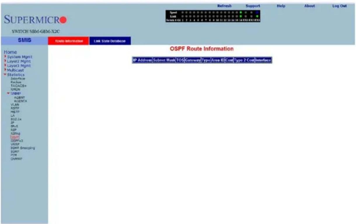
Clicking the ROUTE INFORMATION tab brings up the OSPF ROUTE INFORMATION page (Figure 7-196), which displays information about OSPF routes. The parameters for this page are shown in Table 7-165.
Table 7-165. OSPF Route Information Page Parameters
| Parameter Description | |
| IP Address This parameter specifies the IP address. | |
| Subnet Mask This parameter specifies the Subnet Mask. | |
| TOS This parameter specifies the TOS. | |
| Gateway This parameter specifies the gateway. | |
| Type This parameter specifies the type. | |
| Area ID This parameter specifies the Area ID. | |
| Cost This parameter specifies the cost. | |
| Parameter DescriptionType 2 Cost This parameter specifies the Type 2 cost. | |
| Interface This parameter specifies the interface. | |
OSPF Link State DB
Figure 7-197. OSPF Link State Database Page
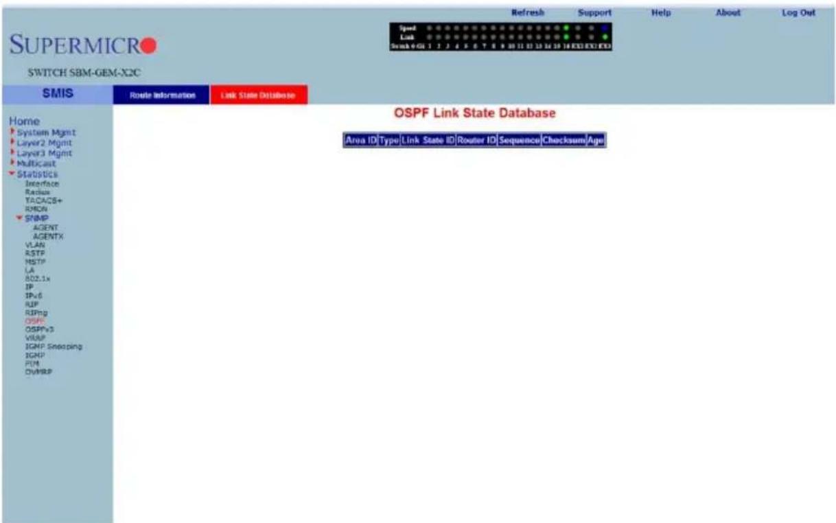
Clicking the LINK STATE DATABASE tab brings up the OSPF LINK STATE DATABASE page (Figure 7-197), which displays information about OSPF link state database. The parameters for this page are shown in Table 7-166.
Table 7-166. OSPF Link State Database Page Parameters
| Parameter Description | |
| Area ID This parameter specifies the area identifier. | |
| Type This parameter specifies the link state type. | |
| Link State ID This parameter specifies the link state identifier. | |
| Router ID This parameter specifies the router identifier. | |
| Sequence | This parameter specifies the sequence number of this link state information. |
| Checksum This parameter specifies the checksum. | |
| Age This parameter specifies the link state information age in seconds. | |
OSPFv3
The OSPFv3 link allows you to view OSPFv3 statistics through the following pages:
- "OSPFV3 Route Information" on page 7-232
- "OSPFV3 Link State DB" on page 7-233
OSPFV3 Route Information
Figure 7-198. OSPFV3 Route Information Page
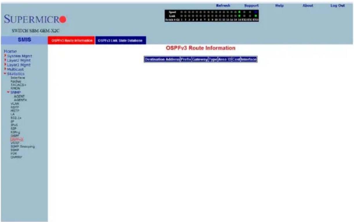
Clicking the OSPFV3 ROUTE INFORMATION tab brings up the OSPFV3 ROUTE INFORMATION page (Figure 7-198), which displays information about OSPFV3 routes. The parameters for this page are shown in Table 7-167.
Table 7-167. OSPFV3 Route Information Page Parameters
| Parameter Description | |
| Destination Address This parameter specifies the destination address. | |
| Prefix This parameter specifies the prefix. | |
| Gateway This parameter specifies the gateway. | |
| Type This parameter specifies the type. | |
| Area ID This parameter specifies the Area ID. | |
| Cost This parameter specifies the cost. | |
| Interface This parameter specifies the interface. | |
OSPFV3 Link State DB
Figure 7-199. OSPFV3 Link State Database Page
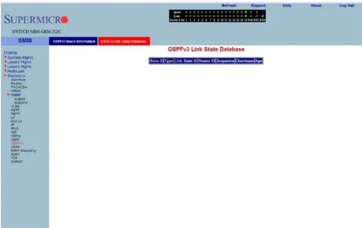
Clicking the OSPFV3 LINK STATE DATABASE tab brings up the OSPFV3 LINK STATE DATABASE page (Figure 7-199), which displays information about OSPF link state database. The parameters for this page are shown in Table 7-168.
Table 7-168. OSPFV3 Link State Database Page Parameters
| Parameter Description | |
| Area ID This parameter specifies the area identifier. | |
| Type This parameter specifies the link state type. | |
| Link State ID This parameter specifies the link state identifier. | |
| Router ID This parameter specifies the router identifier. | |
| Sequence | This parameter specifies the sequence number of this link state information. |
| Checksum This parameter specifies the checksum. | |
| Age This parameter specifies the link state information age in seconds. | |
VRRP Statistics
Figure 7-200. VRRP Statistics Page
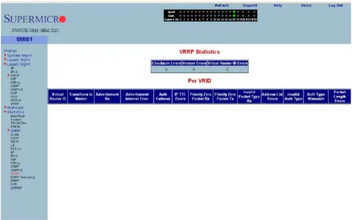
Clicking the VRRP link brings up the VRRP STATISTICS page (Figure 7-200), which displays VRRP global statistics and VRRP router specific statistics. The parameters for this page are shown in Table 7-169.
Table 7-169. VRRP Statistics Page Parameters
| Parameter Description | |
| VRRP Global Statistics | |
| Checksum Errors This parameter specifies the number of checksum errors. | |
| Version Errors This parameter specifies the number of version errors. | |
| Virtual Router ID Errors This parameter specifies the number of Virtual Router ID errors. | |
| VRRP Router Specific Statistics | |
| Virtual Router ID This parameter specifies the Virtual Router identifier. | |
| Transitions to Master This parameter specifies the number of transitions as Master. | |
| Advertisement Receive | This parameter specifies the number of advertisement packets received. |
| Advertisement Internal Error | This parameter specifies the number of advertisement errors happened. |
| Authentication Failures This parameter specifies the number of authentication failures. | |
| IP TTL Errors This parameter specifies the number of IP TTL errors happened. | |
| Priority Zero Packet Received | This parameter specifies the number of priority zero packets received. |
| Priority Zero Packet Transmitted | This parameter specifies the number of priority zero packets transmitted. |
| Invalid Packet Type Received | This parameter specifies the number of invalid packets received. |
| Address List Errors This parameter specifies the number of address list errors. | |
| Invalid Authentication Type | This parameter specifies the number of invalid authentication types received. |
| Authentication Type Mismatch | This parameter specifies the number of authentication type mismatch received. |
| Packet Length Errors | This parameter specifies the number of VRRP packets received with invalid length. |
IGMP Snooping
The IGMP link allows you to view IGMP statistics through the following pages:
- "IGMP Snooping Clear Statistics" on page 7-236
- "IGMP Snooping V1/V2 Statistics" on page 7-237
- "IGMP Snooping V3 Statistics" on page 7-238
IGMP Snooping Clear Statistics
Figure 7-201. IGMP Snooping Clear Statistics Page
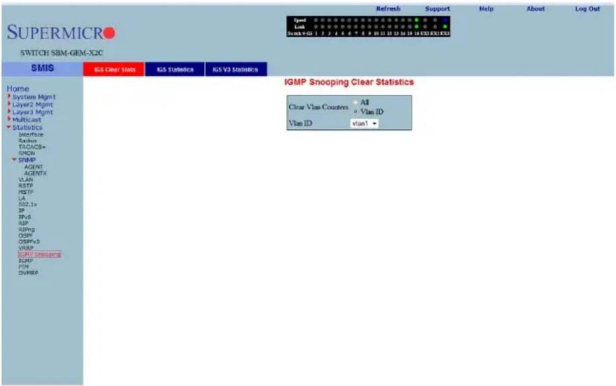
Clicking the IGS CLEAR STATS tab brings up the IGMP SNOOPING CLEAR STATISTICS page (Figure 7-201), which displays clearing IGMP snooping statistics. The parameters for this page are shown in Table 7-170.
Table 7-170. IGMP Snooping Clear Statistics Page Parameters
| Parameter Description | |
| All This parameter gives you | the option to clear all the IGMP statistics. |
| Vlan ID | This parameter give you the option to clear IGMP statistics for a particular VLAN. |
IGMP Snooping V1/V2 Statistics
Figure 7-202. IGMP Snooping V1/V2 Statistics Page
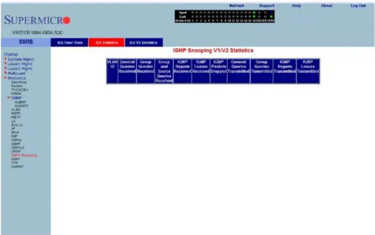
Clicking the IGS STATISTICS tab brings up the IGMP SNOOPING V1/V2 STATISTICS page (Figure 7-202), which displays IGMP snooping statistics. The parameters for this page are shown in Table 7-171.
Table 7-171. IGMP Snooping V1/V2 Statistics Page Parameters
| Parameter Description | |
| VLAN ID This parameter specifies the VLAN identifier. | |
| General Queries Received | This parameter specifies the number of general query packets received. |
| Group Queries Received This parameter specifies the number of group query packets received. | |
| Group and Source Queries Received | This parameter specifies the number of group and source query packets received. |
| IGMP Reports Received This parameter specifies the number of IGMP report packets received. | |
| IGMP Leaves Received This parameter specifies the number of IGMP leave packets received. | |
| IGMP Packets Dropped This parameter specifies the number of IGMP dackets dropped. | |
| General Queries Transmitted | This parameter specifies the number of general query packets transmitted. |
| Group Queries Transmitted | This parameter specifies the number of group query packets transmitted. |
| IGMP Reports Transmitted | This parameter specifies the number of IGMP report packets transmitted. |
| IGMP Leaves Transmitted | This parameter specifies the number of IGMP leave packets transmitted. |
IGMP Snooping V3 Statistics
Figure 7-203. IGMP Snooping V3 Statistics Page
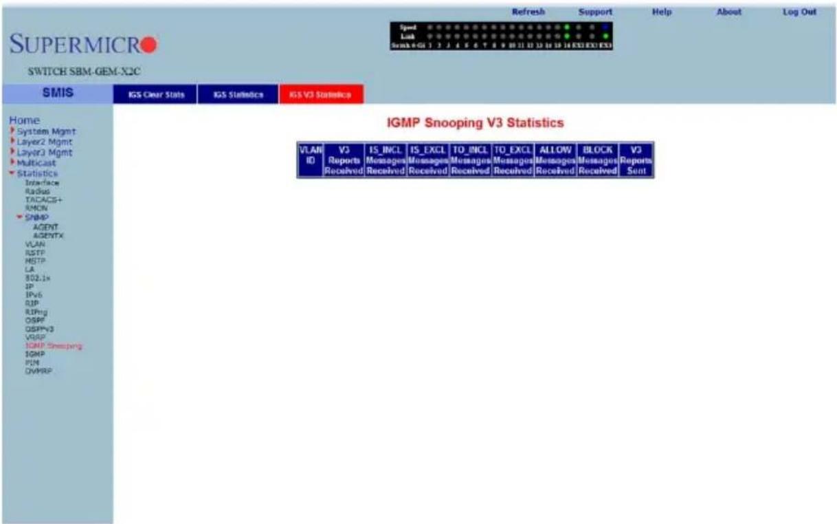
Clicking the IGS V3 STATISTICS tab brings up the IGMP SNOOPING V3 STATISTICS page (Figure 7-203), which displays IGMP snooping V3 statistics information. The parameters for this page are shown in Table 7-172.
Table 7-172. IGMP Snooping V3 Statistics Page Parameters
| Parameter Description | |
| VLAN ID This parameter specifies the VLAN identifier. | |
| V3 Reports Received This parameter specifies the number of Reports messages received. | |
| IS_INCL Messages Received | This parameter specifies the number of messages received with is include field. |
| IS_EXCL Messages Received | This parameter specifies the number of messages received with is exclude field. |
| TO_INCL Messages Received | This parameter specifies the number of messages received with to include field. |
| TO_EXCL Messages Received | This parameter specifies the number of messages received with to exclude field. |
| ALLOW Messages Received | This parameter specifies the number of allow messages received. |
| Parameter DescriptionBLOCK MessagesReceived | This parameter specifies the number of block messages received. |
| V3 Reports Sent This param | meter specifies the number of V3 reports transmitted. |
IGMP Statistics
Figure 7-204. IGMP Route StatisticsPage
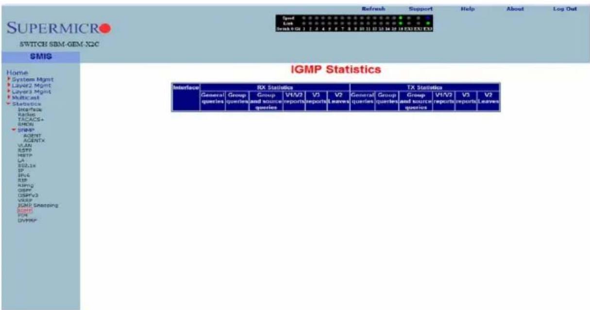
Clicking the IGMP link brings up the IGMP ROUTE STATISTICS page (Figure 7-204), which displays IGMP route information. The parameters for this page are shown in Table 7-173.
Table 7-173. IGMP Route Statistics Page Parameters
| Parameter Description | |
| Interface This parameter specifies the interface identifier. | |
| General Queries Received | This parameter specifies the number of general query packets received. |
| Group Queries Received This parameter specifies the number of group query packets received. | |
| Group and Source Queries Received | This parameter specifies the number of group and source query packets received. |
| IGMP V1/V2 Reports Received | This parameter specifies the number of IGMP V1/V2 report packets received. |
| IGMP V3 Reports Received | This parameter specifies the number of IGMP V3 report packets received. |
| General Queries Transmitted | This parameter specifies the number of general query packets transmitted. |
| Group Queries Transmitted | This parameter specifies the number of group query packets transmitted. |
| Group and Source Queries Transmitted | This parameter specifies the number of group and source query packets transmitted. |
PIM
The PIM link allows you to view PIM statistics through the following pages:
• "PIM Interface Statistics" on page 7-241
• "PIM Neighbor Statistics" on page 7-242
• "PIM BSR Info" on page 7-243
• "PIM RP Set Information" on page 7-244
• "PIM Route Information" on page 7-245
PIM Interface Statistics
Figure 7-205. PIM Interface Statistics Page
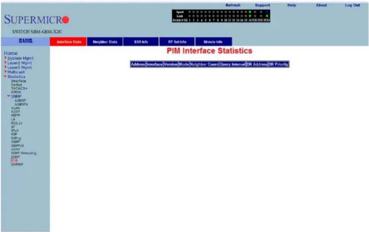
Clicking the INTERFACE STATS tab brings up the PIM INTERFACE STATISTICS page (Figure 7-205), which displays PIM interface statistics. The parameters for this page are shown in Table 7-174.
Table 7-174. PIM Interface Statistics Page Parameters
| Parameter Description | |
| Address This parameter specifies the address. | |
| Interface This parameter specifies the interface. | |
| Version This parameter specifies the version. | |
| Mode This parameter specifies the mode. | |
| Neighbor Count This parameter specifies the neighbor count. | |
| Query Interval This parameter specifies the query interval. | |
| DR address This parameter specifies the DR address. | |
| DR Priority This parameter specifies the DR priority. | |
PIM Neighbor Statistics
Figure 7-206. PIM Neighbor Statistics Page
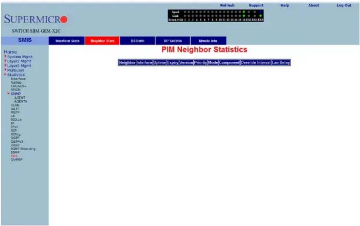
Clicking the NEIGHBOR STATS tab brings up the PIM NEIGHBOR STATISTICS page (Figure 7-206), which displays PIM neighbor statistics. The parameters for this page are shown in Table 7-175.
Table 7-175. PIM Neighbor Statistics Page Parameters
| Parameter Description | |
| Neighbor This parameter specifies the neighbor. | |
| Interface This parameter specifies the interface. | |
| Uptime This parameter specifies the uptime. | |
| Expiry This parameter specifies the expiry. | |
| Version This parameter specifies the version. | |
| Priority This parameter specifies the priority. | |
| Mode This parameter specifies the mode. | |
| Component This parameter specifies the component. | |
| Override Interval This parameter specifies the override interval. | |
| LAN Delay This parameter specifies the LAN delay. | |
PIM BSR Info
Figure 7-207. PIM BSR Info Page
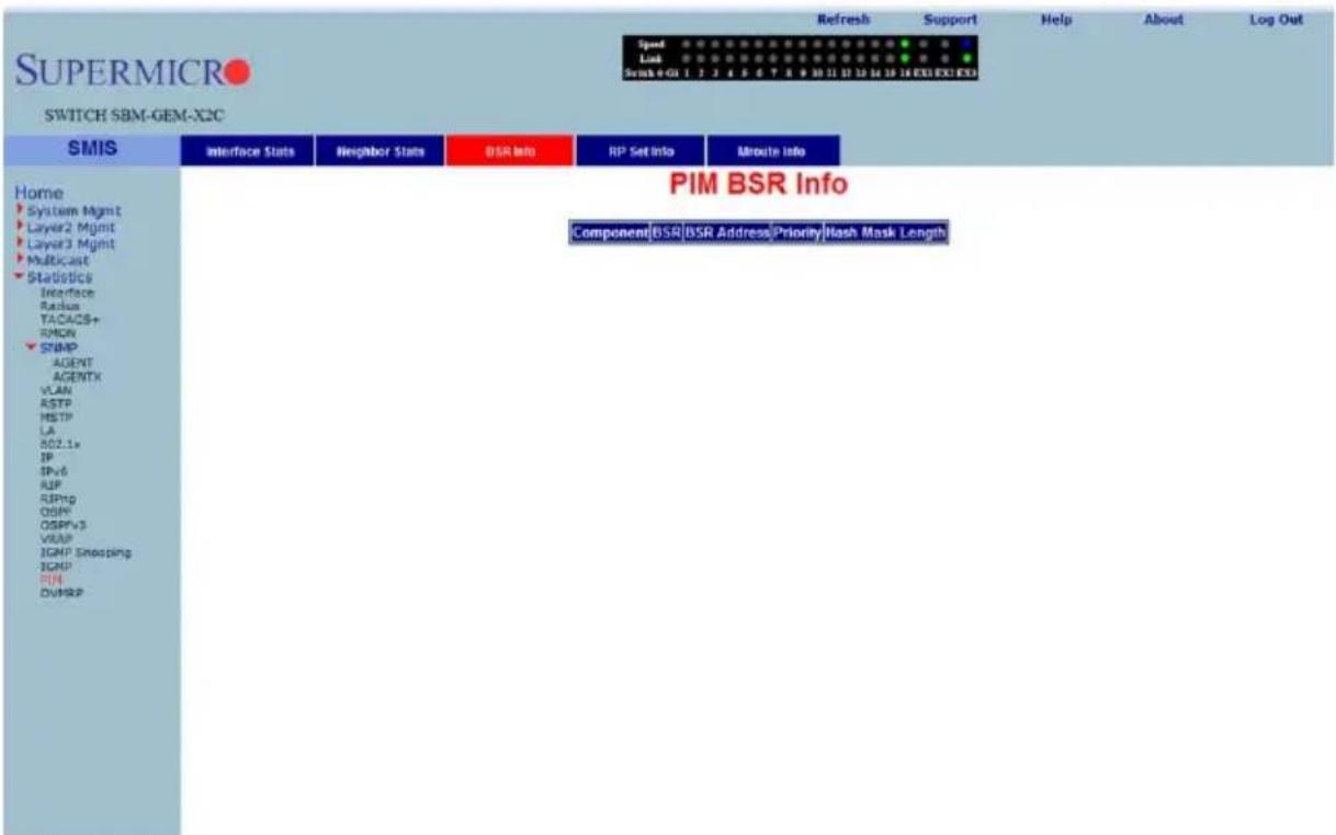
Clicking the BSR INFO tab brings up the PIM BSR INFO page (Figure 7-207). The parameters for this page are shown in Table 7-176.
Table 7-176. PIM BSR Info Page Parameters
| Parameter Description | |
| Component This parameter specifies the component. | |
| BSR This parameter specifies the BSR. | |
| BSR Address This parameter specifies the BSR address. | |
| Priority This parameter specifies the priority. | |
| Hash Mask Length This parameter specifies the Hash Mask Length. | |
PIM RP Set Information
Figure 7-208. PIM RP Information Page
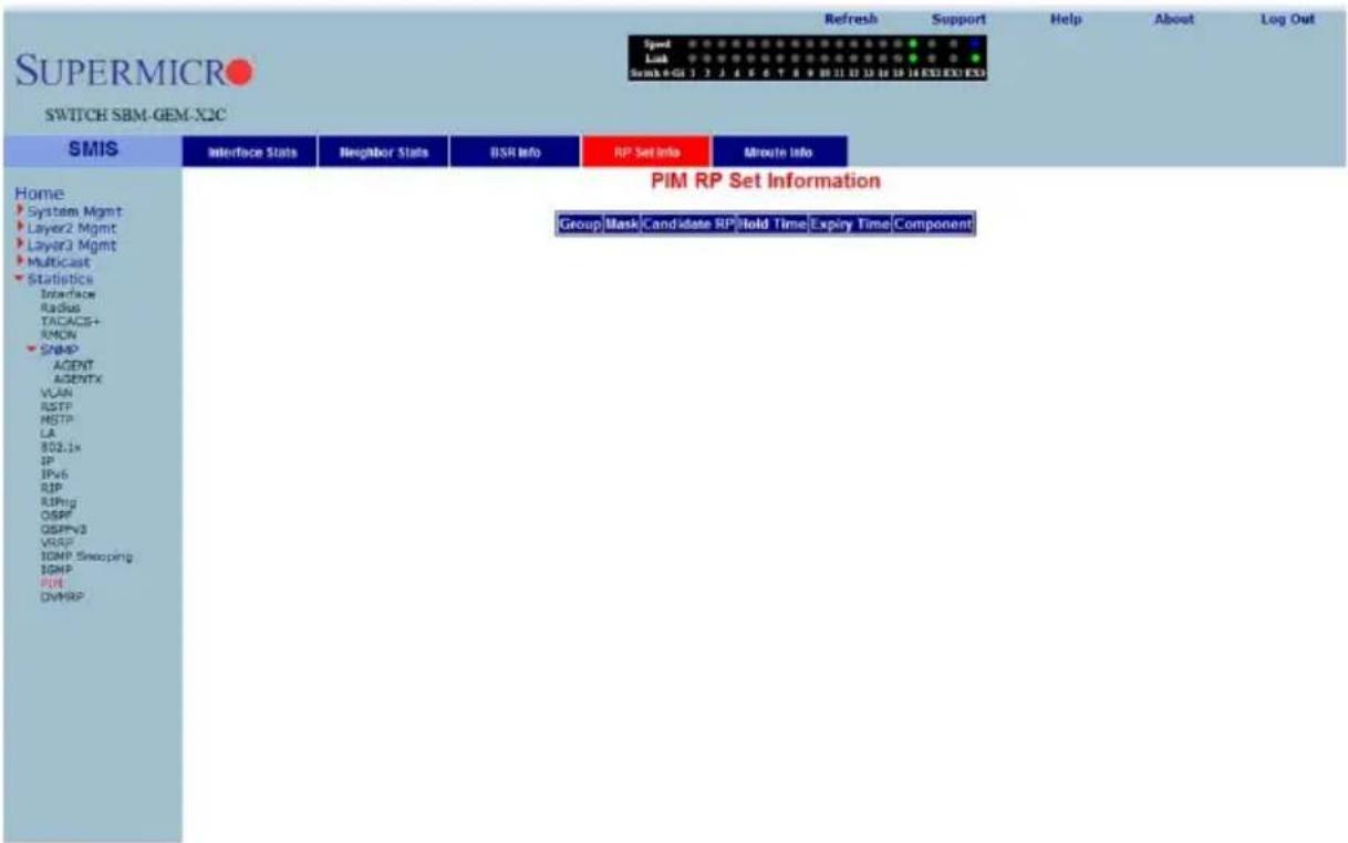
Clicking the RP SET INFO tab brings up the PIM RP INFORMATION page (Figure 7-208), which displays PIM RP information. The parameters for this page are shown in Table 7-177.
Table 7-177. PIM RP Information Page Parameters
| Parameter Description | |
| Group This parameter specifies the group address. | |
| Mask This parameter specifies the mask. | |
| Candidate RP This parameter specifies the candidate RP. | |
| Hold Time This parameter specifies the Hold time in seconds. | |
| Expiry Time This parameter specifies the expiry time in seconds. | |
| Component This parameter specifies the component identifier. | |
PIM Route Information
Figure 7-209. PIM Route Information Page
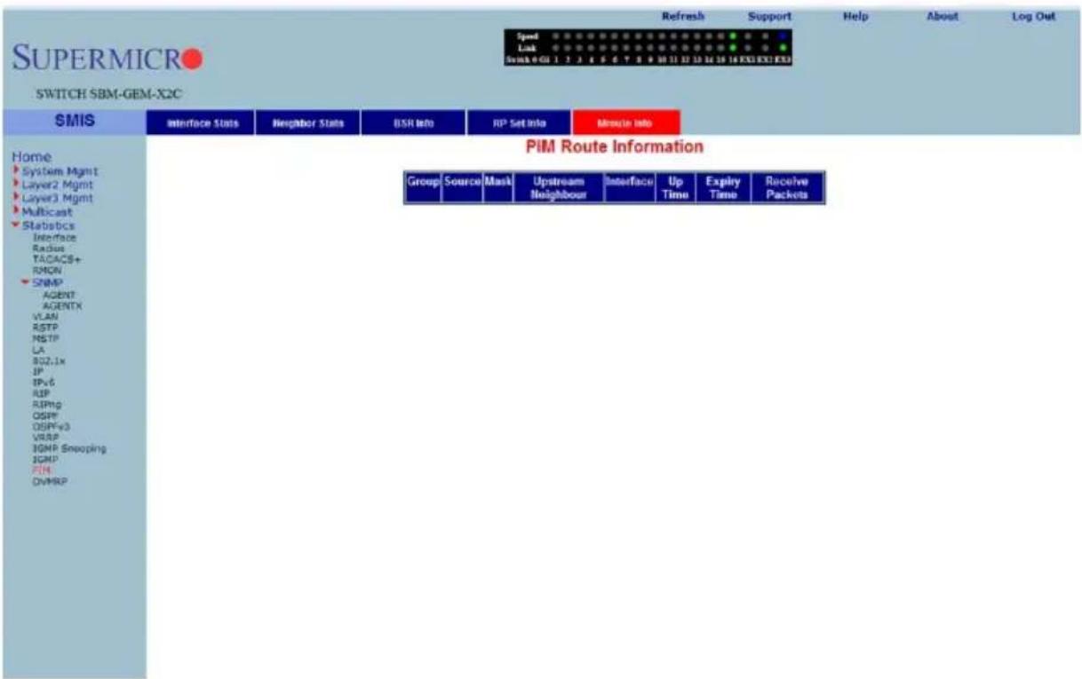
Clicking the MROUTE INFO tab brings up the PIM ROUTE INFORMATION page (Figure 7-209), which displays PIM route information. The parameters for this page are shown in Table 7-178.
Table 7-178. PIM Route Information Page Parameters
| Parameter Description | |
| Group This parameter specifies the group address. | |
| Source This parameter specifies the source address. | |
| Mask This parameter specifies the PIM route mask. | |
| Upstream Neighbor This parameter specifies the upstream neighbor address. | |
| Interface This parameter specifies the | |
| Up Time This parameter specifies the up time in seconds. | |
| Expiry Time This parameter specifies the expiry time in seconds. | |
| Receive Packets This parameter specifies the number of packets received. | |
DVMRP
The DVMRP link allows you to view DVMRP statistics through the following pages:
• "DVMRP Routers" on page 7-246
• "DVMRP Multicast Routers" on page 7-247
• "DVMRP Prune Statistics" on page 7-248
DVMRP Routers
Figure 7-210. DVMRP Routes Page
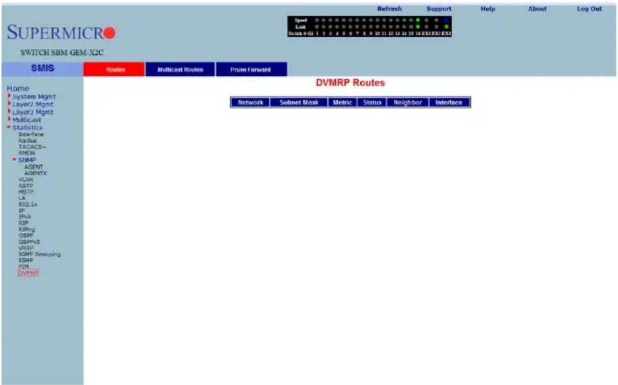
Clicking the ROUTES tab brings up the DVMRP ROUTES page (Figure 7-210), which displays DVMRP routes information. The parameters for this page are shown in Table 7-179.
Table 7-179. DVMRP Routes Page Parameters
| Parameter Description | |
| Network This parameter specifies the network address for this route. | |
| Subnet Mask This parameter specifies the network mask for this route. | |
| Metric This parameter specifies the metric value for this route. | |
| Status This parameter specifies the status of this route. | |
| Neighbor This parameter specifies the neighbor address for this route. | |
| Interface This parameter specifies the interface identifier. | |
DVMRP Multicast Routers
Figure 7-211. DVMRP Multicast Routes Page
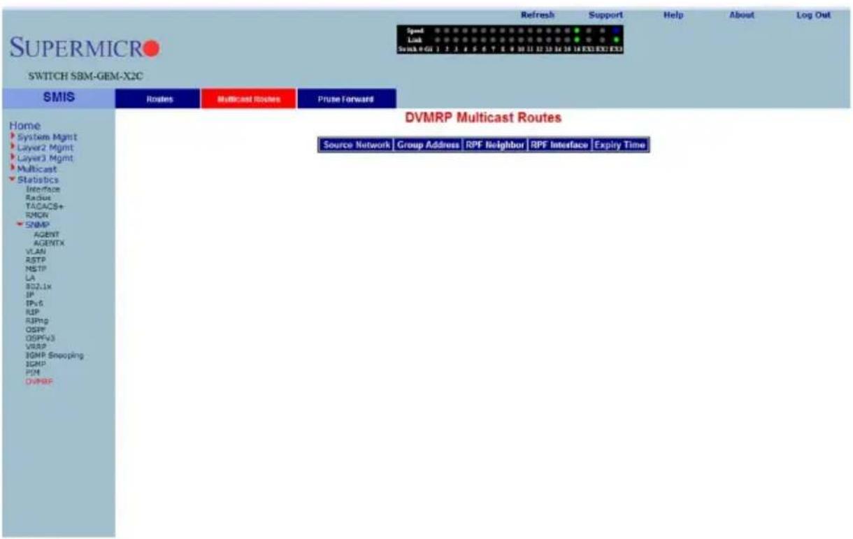
Clicking the MULTICAST ROUTES tab brings up the DVMRP MULTICAST ROUTES page (Figure 7-211), which displays DVMRP multicast routes information. The parameters for this page are shown in Table 7-180.
Table 7-180. DVMRP Multicast Routes Page Parameters
| Parameter Description | |
| Source Network This parameter specifies the source network. | |
| Group Address This parameter specifies the group address. | |
| RPF Neighbor This parameter specifies the RPF neighbor. | |
| RPF Interface This parameter specifies the RPF interface. | |
| Expiry Time This parameter specifies the expiry time in seconds. | |
DVMRP Prune Statistics
Figure 7-212. DVMRP Prune Statistics Page
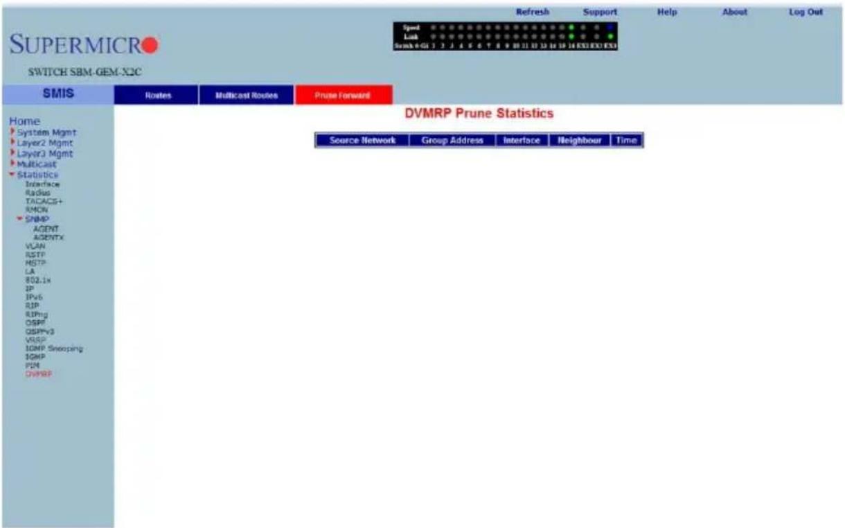
Clicking the PRUNE FORWARD tab brings up the DVMRP PRUNE STATISTICS page (Figure 7-212), which DVMRP prune statistics information. The parameters for this page are shown in Table 7-181.
Table 7-181. DVMRP Prune Statistics Page Parameters
| Parameter Description | |
| Source Network Address This parameter specifies the source network address. | |
| Group Address This parameter specifies the group address. | |
| Interface Identifier. This parameter specifies the interface identifier. | |
| Neighbor Address This parameter specifies the neighbor address. | |
| Time This parameter specifies the time in seconds. | |
Notes
Appendix A HCA Mezzanine Cards
This appendix describes safety guidelines, features and installation of HCA Mezzanine cards used with the InfiniBand and 10-Gb switch module. See Chapter 4 for further details on the InfiniBand module. See Chapter 5 for further details on the 10-Gb switch module.
A-1 Safety Guidelines
To avoid personal injury and property damage, carefully follow all the safety steps listed below when accessing your system or handling the components.
ESD Safety Guidelines
Electric Static Discharge (ESD) can damage electronic components. To prevent damage to your system, it is important to handle it very carefully. The following measures are generally sufficient to protect your equipment from ESD.
- Use a grounded wrist strap designed to prevent static discharge.
- Touch a grounded metal object before removing a component from the antistatic bag.
- Handle the add-on card by its edges only; do not touch its components, peripheral chips, memory modules or gold contacts.
- When handling chips or modules, avoid touching their pins.
- Put the card and peripherals back into their antistatic bags when not in use.
General Safety Guidelines
- Always disconnect power cables before installing or removing any components from the computer.
- Disconnect the power cable before installing or removing any cables from the system.
- Make sure that the add-on card is securely and properly installed on the motherboard to prevent damage to the system due to power shortage.
A-2 Mezzanine HCA Cards
Available Mezzanine HCA cards for use with the SuperBlade InfiniBand switch are shown in the following sections.

NOTE: All images and layouts shown in this user's guide are based upon the latest PCB Revision available at the time of publishing. The card you have received may or may not look exactly the same as the graphics shown in this manual.
AOC-IBH-001 Mezzanine HCA Card
The AOC-IBH-001 card has dual 4x DDR IB ports and uses a Mellanox Infinihost III Ex DDR chip. This card is no longer in production (EOL), but users of this card can consider replacement with the AOC-IBH-XDD Mezzanine HCA card as an alternative.
Figure A-1. AOC-IBH-001 Mezzanine HCA Card
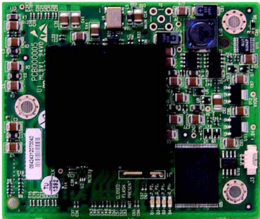
natural_image
Close-up of a green printed circuit board with various electronic components and connectors (no readable text or symbols)AOC-IBH-002 Mezzanine HCA Card
The AOC-IBH-002 card has a single 4x DDR 20-Gbps IB port and uses a Mellanox InfiniHost III Lx DDR chip.
Figure A-2. AOC-IBH-002 Mezzanine HCA Card
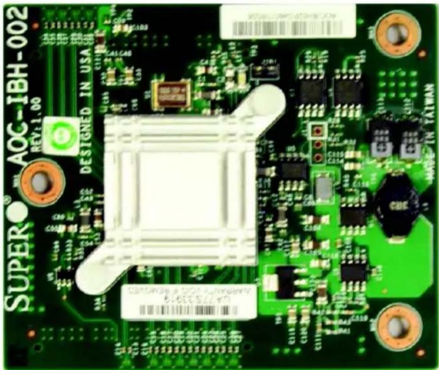
AOC-IBH-003 Mezzanine HCA Card
The AOC-IBH-003 card has dual ports that can be either 4xDDR IB or 10Gbps Ethernet and uses a Mellanox ConnectX chip. This card is no longer in production (EOL), but users of this card can consider replacement with the AOC-IBH-XDD Mezzanine HCA card as an alternative.
Figure A-3. AOC-IBH-003 Mezzanine HCA Card
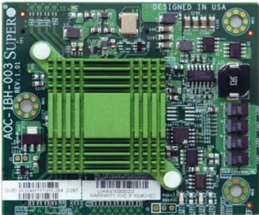
AOC-IBH-XDS Mezzanine HCA Card
The AOC-IBH-XDS card has a single 4x DDR 20-Gbps port that can be either 4x DDR IB or 10-Gbps Ethernet and uses a Mellanox ConnectX chip. This card comes with a removable extender flange, like the one shown in Figure A-6: "AOC-IBH-XQS Mezzanine HCA Card" on page A-7, that allows it to be installed in all compatible SuperBlade servers.
Figure A-4. AOC-IBH-XDS Mezzanine HCA Card
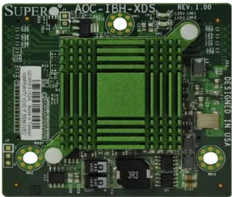
AOC-IBH-XDD Mezzanine HCA Card
The AOC-IBH-XDD card has dual 4x DDR 20-Gbps ports that can be either 4x DDR IB or 10-Gbps Ethernet and uses a Mellanox ConnectX chip. This card comes with a removable extender flange, like the one shown in Figure A-6: "AOC-IBH-XQS Mezzanine HCA Card" on page A-7, that allows it to be installed in all compatible SuperBlade servers.
Figure A-5. AOC-IBH-XDD Mezzanine HCA Card
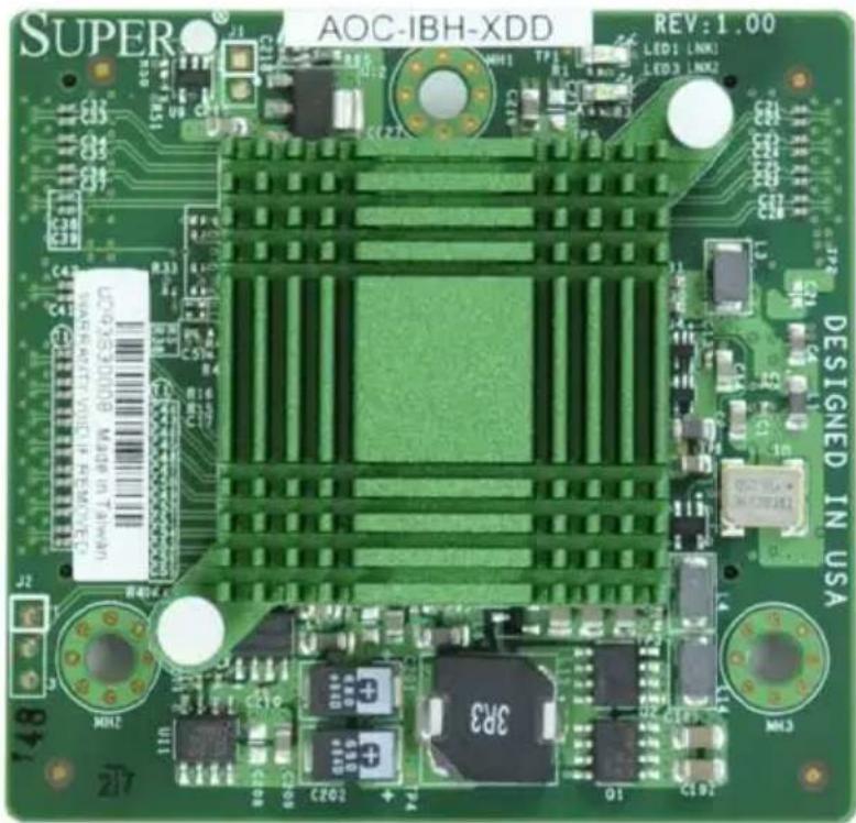
AOC-IBH-XQS Mezzanine HCA Card
The AOC-IBH-XQS card has a single 4x QDR 40-Gbps port, and uses a Mellanox ConnectX chip. This card comes with a removable extender flange (shown in Figure A-6), that allows it to be installed in all compatible SuperBlade servers.
Figure A-6. AOC-IBH-XQS Mezzanine HCA Card
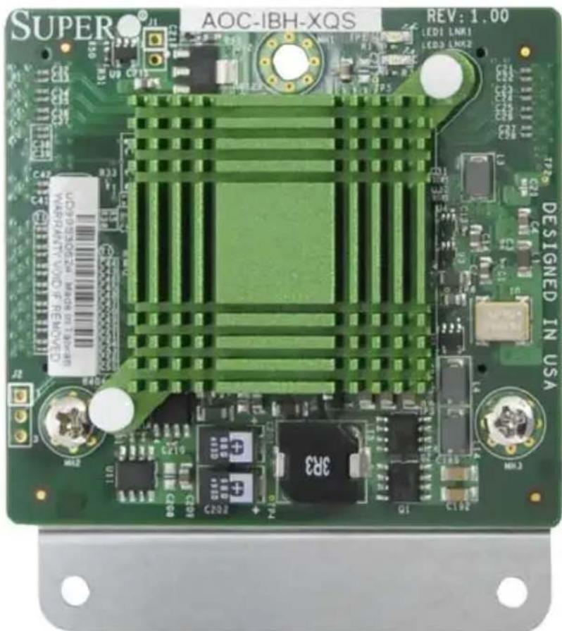
AOC-IBH-XQD Mezzanine HCA Card
The AOC-IBH-XQS card has dual 4x QDR 40-Gbps ports, and uses a Mellanox ConnectX chip. This card comes with a removable extender flange (like the one shown in Figure A-6: "AOC-IBH-XQS Mezzanine HCA Card" on page A-7), that allows it to be installed in all compatible SuperBlade servers.
Figure A-7. AOC-IBH-XQD Mezzanine HCA Card
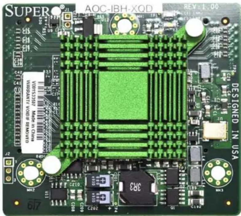
A-3 Installation
Figure A-8. Installation Location
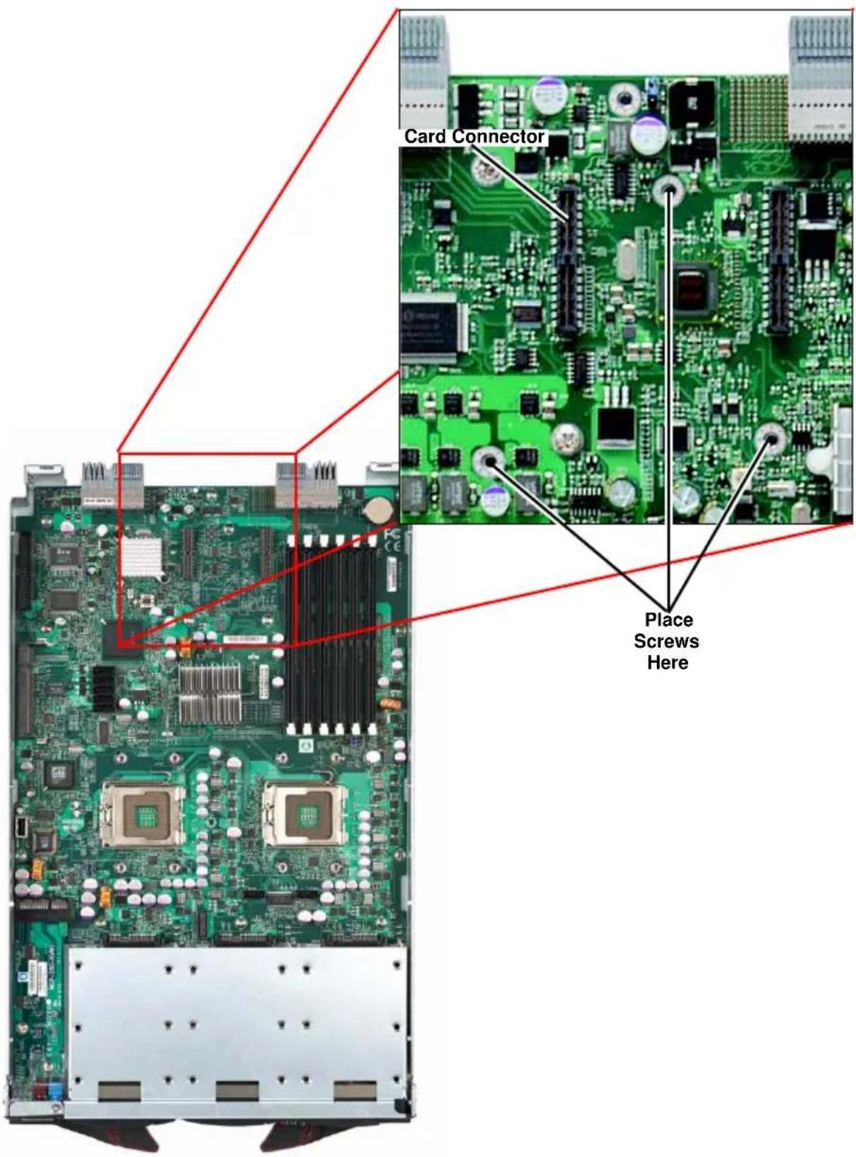
Installation Location
All models of the Mezzanine HCA card are compatible with both SBI and SBA blade modules. The AOC-IBH-XQS and AOC-IBH-XQD cards are only compatible with the latest SBI and SBA models. For the latest compatibility information, see our web site:
http://www.supermicro.com/products/superblade/
Card Installation
To Install an HCA Card:
- Confirm that you have the correct card and three (3) screws.
- Following the instructions from the SuperBlade Manual, remove the blade module and open the cover to access the mainboard.
- In a standard, electro-magnetically protected workstation, secure the card to the serverboard by gently but firmly attaching the card to the two connectors.
- Using a Phillips screw driver, secure and tighten each screw one at a time. Do not overtighten the screws.

NOTE: The latest models of the Supermicro InfiniBand HCA card have a smaller form factor to make them compatible with newer blade modules. The newer HCAs come from the factory with an extender bracket attached to allow installation in older blade modules.
For installation in newer blade modules, first remove the extender bracket by removing the two screws with a Phillips screwdriver. Then follow the above instructions for installation on the blade module itself.
Figure A-9. Card Installation
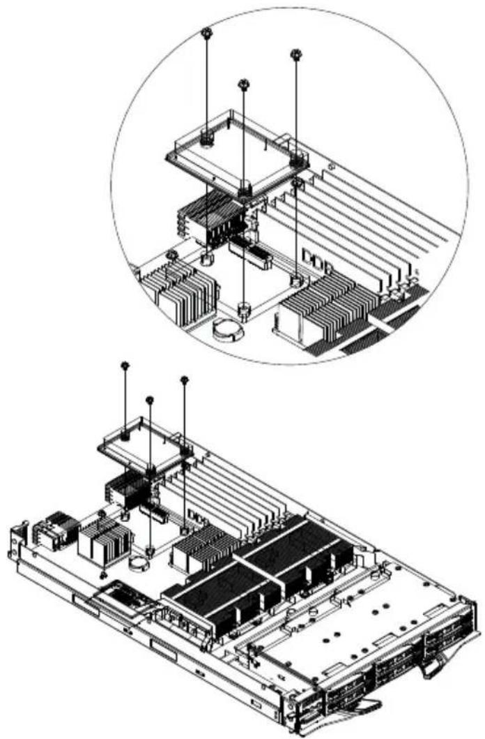
natural_image
Technical illustration of a server rack with an inset close-up showing internal components (no text or symbols)Figure A-10. Installation Complete
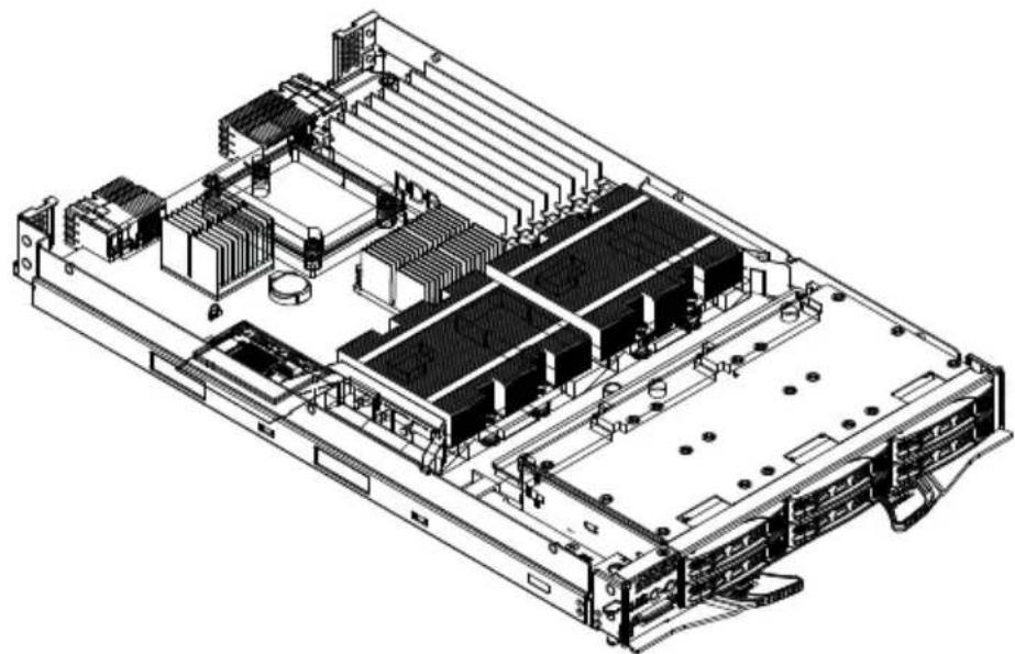
natural_image
Technical line drawing of a server rack with multiple drive bays and internal components (no text or labels)Notes
Appendix B LED Descriptions
This appendix covers LED descriptions for the blade enclosure and other module components. The LED descriptions for the InfiniBand switch, Gigabit Ethernet modules and Blade modules are included here for your reference.
B-1 Gigabit Ethernet Module LED Descriptions
SBM-GEM-001 Gigabit Ethernet module and SBM-GEM-002 Pass-through module LEDs are described below in Table B-1.
Table B-1. Gigabit Ethernet Switch LED Indicators
| LED State Description | ||
| Module Initiation OK LED(GEM-001 Module Only) | Steady On | The GEM-001 GbE switch module is operational and has passed the POST (Power-On Self-Test) with no critical faults. |
| Module Fault LED(Red)(GEM-001 Module Only) | Steady On | When lit, this LED indicates that the GEM-001 GbE switch module has either failed the POST or has detected an operational fault within the module. When this LED is lit, the fault LED on the blade enclosure will also turn on. |
| Link/Activity Ethernet Port Status LED | Solid Green ThisBlinking GreenOff This indicates that no link is established | indicates that the link is established, no activityThis indicates that data is being transmitted (Tx) or received (Rx) |
| Speed Ethernet Port Status LED(GEM-001 Module Only) | Amber Connection speed of the port is 1 Gb/secGreen Connection speed of the port is 100 Mb/secOff Connection speed of the port is 10 Mb/sec | |
B-2 1/10 Gigabit Ethernet Module LED Descriptions
The SBM-GEM-X2C/+ 1/10 Gbps Ethernet module and XEM-002 10GbE Pass-through Module LEDs are described below in Table B-2.
Table B-2. 1/10 Gigabit Ethernet Switch LED Indicators
| LED State Description | ||
| RJ45 Link/Activity (GEM-X2C Module Only) | Green | Solid denotes link established, no activity. Blinking denotes activity. Off indicates that no link is established. |
| RJ45 Speed (GEM-X2C Module Only) | Amber/Green/Off | Amber denotes 1 Gbps speed.Green denotes 100 Mbps speed.Off denotes 10 Mbps speed. |
| “Initiation OK” LED Blue Denotes successful initiation/OK status when solidly lit. | ||
| Module Fault LED | Red | Denotes SBM-GEM-001 module failure when solidly lit. |
| 10G Port LEDs Green | Denotes activity for 10Gbps port when solidly lit. Blinking green denotes data transmitted (Tx) or received (Rx). | |
| Stack ID LEDs (GEM-X2C Module Only) | Green | Denotes Stack ID activity as shown in Table B-3 below. |
Table B-3. Stacking LED Activity
| Stack LED 4 Stack | LED 3 Stack | LED 2 Stack | LED 1 | Stacking Switch Identifier |
| OFF | OFF | OFF | ON | 1 |
| OFF | OFF | ON | OFF | 2 |
| OFF | OFF | ON | ON | 3 |
| OFF | ON | OFF | OFF | 4 |
| OFF | ON | OFF | ON | 5 |
| OFF ON | ON | OFF | 6 | |
| OFF | ON | ON | ON | 7 |
| ON | OFF | OFF | OFF | 8 |
| ON | OFF | OFF | ON | 9 |
| ON | OFF | ON | OFF | 10 |
| ON | OFF | ON | ON | 11 |
| ON | ON | OFF | OFF 12 | |
| ON | ON | OFF | ON | 13 |
| ON | ON | ON | OFF 14 | |
| ON | ON | ON | ON | 15 |
| OFF OFF | OFF | OFF 16 / Stacking Disabled. | ||
B-3 SBM-IBS-001 InfiniBand Switch LED Descriptions
SBM-IBS-001 InfiniBand switch module LEDs are found below in Table B-4.
Table B-4. SBM-IBS-001 InfiniBand Switch LEDs
| LED State Indication Description | ||
| Module Status LED | Blink Switch is booting its firmwareSteady On Boot process failedOff Switch is properly booted and operational | |
| Module Power LED (Green) | Steady On Switch has power and is operationalOff There is a problem with the power being supplied to the switch. | |
| Port Physical Link LED (Green) | Steady On Physical link establishedBlink Physical link error, poor connection qualityOff Port is off or has no physical connection | |
| Port Activity LED (Yellow) | Steady On Logic link established, no activityBlinking Data transferring to/from the portOff Logical link is down | |
Notes
B-4 SBM-IBS-Q3616/M InfiniBand Switch LED Descriptions
SBM-IBS-Q3616/M InfiniBand switch module LEDs are found below in Table B-5.
Table B-5. SBM-IBS-Q3616/M InfiniBand Switch LEDs
| LED State Indication Description | ||
| Module Status LED | Blink Switch is booting its firmwareSteady On Boot process failedOff Switch is properly booted and operational | |
| Module Power LED (Green) | Steady On Switch has power and is operationalOff There is a problem with the power being supplied to the switch. | |
| Port Physical Link LED (Green) | Steady On Physical link establishedBlink Physical link error, poor connection qualityOff Port is off or has no physical connection | |
| Port Activity LED (Yellow) | Steady On Logic link established, no activityBlinking Data transferring to/from the portOff Logical link is down | |
Appendix C Installing Triple Wide Bays
This appendix describes the setup for triple-wide module bays used by the InfiniBand pass-through module. See Chapter 4 for further details on InfiniBand modules.
C-1 Installing a Triple Wide Module Bay
Use the procedure below for installing a triple-wide module bay in a Superblade chassis.
Installing a Triple-Wide Module Bay
- Remove the four screws that secure the inner enclosure to the main enclosure. Slide the inner enclosure outward, depressing the locking tabs on both sides to pull it completely out.
- Remove any single-wide modules that are occupying the bays you wish to modify to a triple-wide bay. See Figure C-1, Step 1 & 2 for details.
Figure C-1. Step 1 & 2
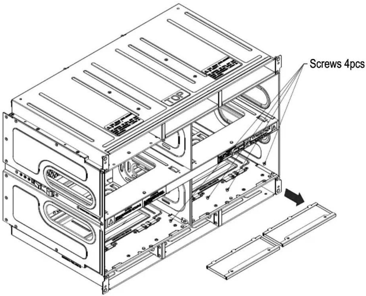
- In the module bay you wish to expand to triple wide, remove the two screws that secure the center support to the inner enclosure then take out the center support.
- Remove the two screws from the underside of each of the two horizontal spacers. See Figure C-2, Step 3 & 4 for details.
Figure C-2. Step 3 & 4
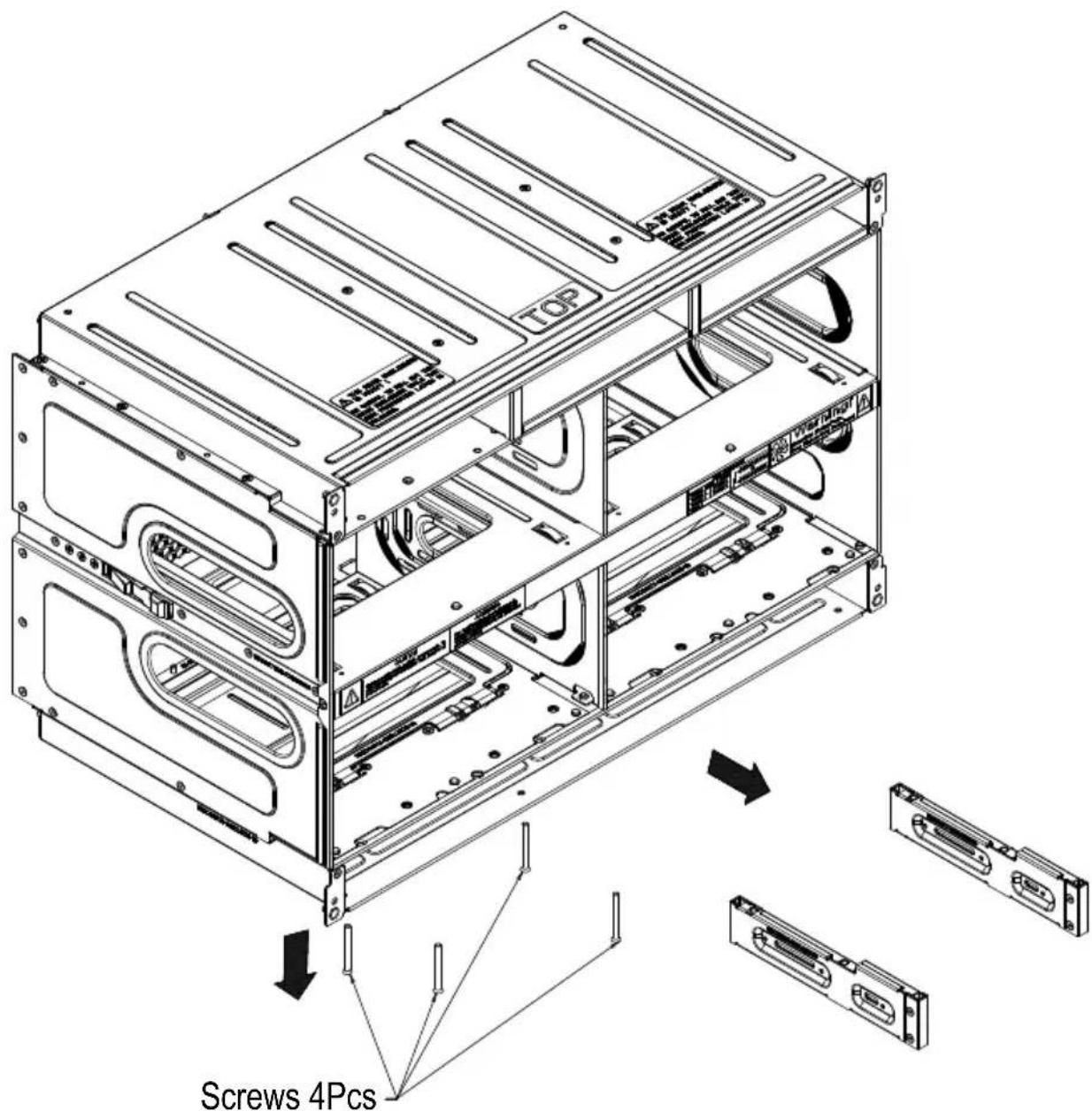
- Using four screws, install the long horizontal spacer to the same space where the two short spacers were removed. See Figure C-3, Step 5 for details.
Figure C-3. Step 5
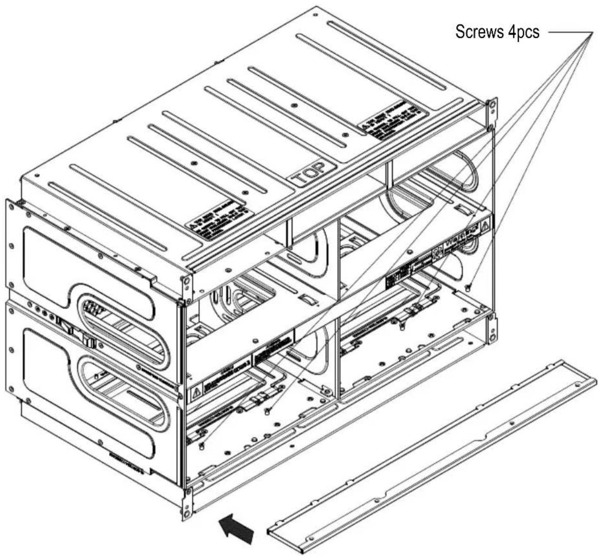
- You can now install a double-wide module into the bay. See Figure C-4, Step 6 for details.
Figure C-4. Step 6
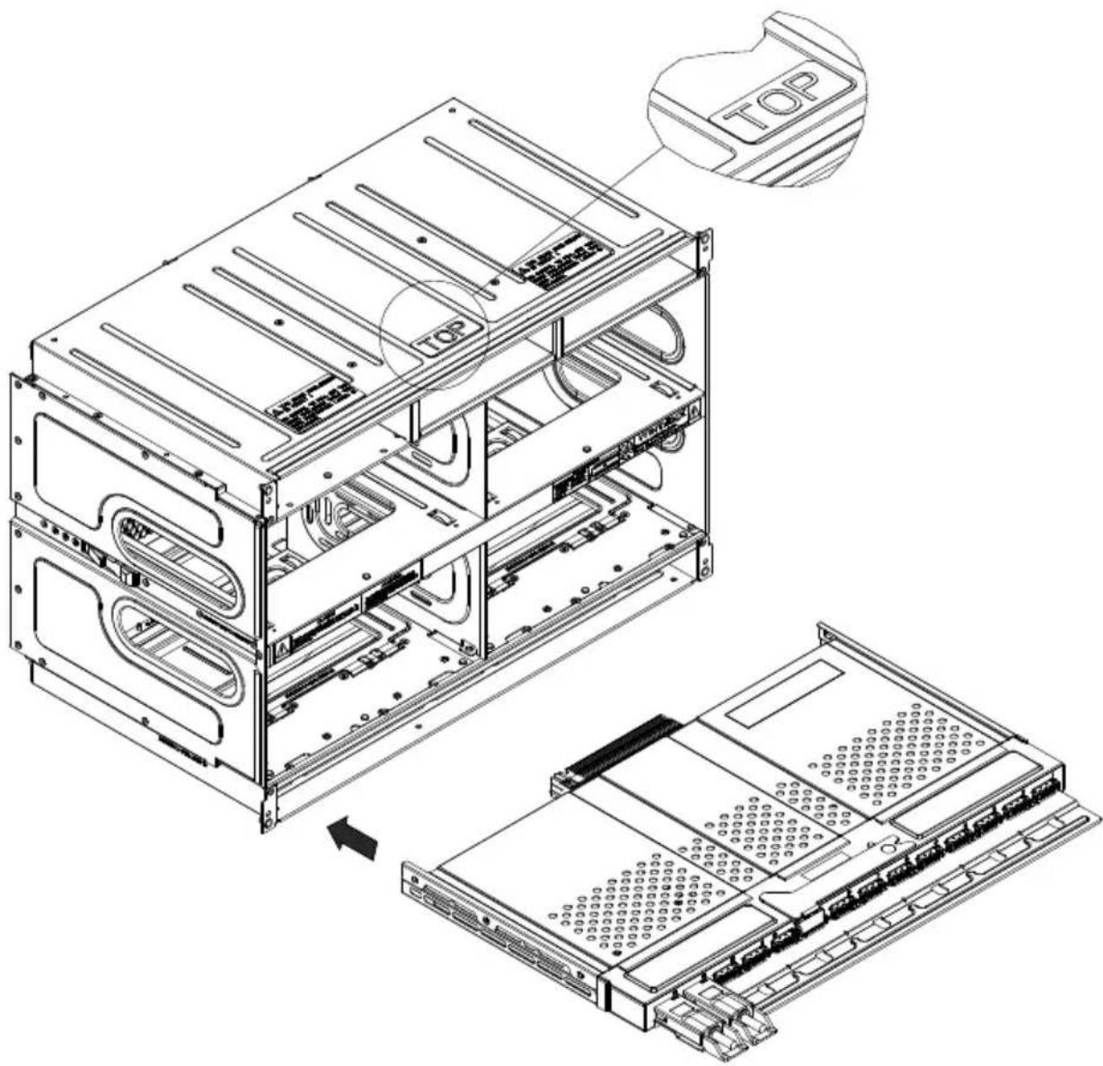

NOTE: This procedure describes modifying three right most single-wide bays located at the bottom of the inner enclosure. The same procedure applies to the three right most single bays located at the top of the enclosure, but note that the horizontal spacers in the bottom bays use a guide pin and are not interchangeable with the upper bay spacers.
Modules in the upper bays will have their release handles on the bottom, while modules in the lower bays will have their release handles on the top.
Placing modules in an "upside-down" orientation in an upper-bay (only) does not affect their operation.

NOTE: Only one triple-wide module can be installed in an enclosure since each enclosure requires at least one CMM module. The bottom location is recommended.
If using the AOC-IBH-002 single-port InfiniBand mezzanine card, the InfiniBand pass-through module MUST be installed in the bottom location.
Notes
Disclaimer
The products sold by Supermicro are not intended for and will not be used in life support systems, medical equipment, nuclear facilities or systems, aircraft, aircraft devices, aircraft/emergency communication devices or other critical systems whose failure to perform be reasonably expected to result in significant injury or loss of life or catastrophic property damage. Accordingly, Supermicro disclaims any and all liability, and should buyer use or sell such products for use in such ultra-hazardous applications, it does so entirely at its own risk. Furthermore, buyer agrees to fully indemnify, defend and hold Supermicro harmless for and against any and all claims, demands, actions, litigation, and proceedings of any kind arising out of or related to such ultra-hazardous use or sale.
- User's Manual
- Table of Contents
- Chapter 1 Introduction....1-1
- Chapter 2 System Safety....2-1
- Chapter 3 Setup and Installation....3-1
- Chapter 4 InfiniBand Modules ...... 4-1
- Chapter 5 Ethernet Modules ....5-1
- Chapter 6 1-Gb Ethernet Switch Firmware ......6-1
- Chapter 7 1/10-Gb Ethernet Switch Firmware....7-1
- Appendix A HCA Mezzanine Cards ......A-1
- Appendix B LED Descriptions....B-1
- Appendix C Installing Triple Wide Bays ...... C-1
- List of Figures
- Notes
- List of Tables
- Preface
- About this Manual
- Manual Organization
- Chapter 1: Introduction
- Chapter 2: System Safety
- Chapter 3: Setup and Installation
- Chapter 4: InfiniBand Modules
- Chapter 5: Ethernet Modules
- Chapter 6: 1-Gb Ethernet Switch Firmware
- Chapter 7: 1/10-Gb Ethernet Switch Firmware
- Appendix A: HCA Mezzanine Cards
- Appendix B: LED Descriptions
- Appendix C: Installing Triple Wide Bays
- Chapter 1 Introduction
- 1-1 Overview
- 1-2 Product Checklist of Typical Components
- 1-3 Features
- 1-4 Contacting Supermicro
- Headquarters
- Europe
- Asia-Pacific
- Chapter 2 System Safety
- 2-1 Electrical Safety Precautions
- 2-2 General Safety Precautions
- 2-3 Electrostatic Discharge Precautions
- 2-4 Operating Precautions
- Chapter 3 Setup and Installation
- 3-1 Installing/Removing a Switch Module
- Installing a Switch Module
- Removing a Switch Module
- 3-2 Configuring the Switch Module
- Web-based Management Utility/IPMI
- Network Connection
- Logging In to the IPMI:
- Address Defaults
- Command Line
- Accessing CLI through Telnet:
- Accessing CLI through a Serial Console
- 3-3 SBM-GEM-X2C/+ 1/10 Gigabit Ethernet Switch Firmware
- Firmware Upgrading Procedures
- Upgrading Firmware on the Switch using TFTP:
- Booting using a Fallback Firmware Image:
- Upgrading Fallback Firmware using TFTP:
- Firmware Failure Recovery Steps
- Recovering Switch Functionality with a Firmware Image:
- Chapter 4 InfiniBand Modules
- 4-1 Overview
- 4-2 SBM-IBS-001 4X DDR InfiniBand Switch Module
- 4-3 SBM-IBS-Q3618/Q3616 4X QDR InfiniBand Switch Module
- 4-4 SBM-IBS-Q3616M 4X QDR InfiniBand Switch Module
- 4-5 SBM-IBP-D14 InfiniBand Pass-Through Module
- 4-6 Installation and Configuration of InfiniBand Switch Modules
- Installing/Removing the InfiniBand Switch Module
- Installing the Module
- Removing the Module
- Installing/Removing the InfiniBand Pass-Through Module
- InfiniBand Switch LEDs
- Blade Software for Access to InfiniBand Switch Module
- Chapter 5 Ethernet Modules
- 5-1 SBM-GEM-001 Gigabit Ethernet Switch Module
- LED Indicators
- Ports
- 5-2 SBM-GEM-X2C 1/10 Gb Ethernet Switch Module
- 5-3 SBM-GEM-002 1Gb Ethernet Pass-through Module
- 5-4 SBM-XEM-002/SBM-XEM-002M 10 Gb Ethernet Pass-through Module
- 5-5 SBM-GEP-T20 1Gb Ethernet Pass-through Module for Twin-Blade Modules
- Chapter 6 1-Gb Ethernet Switch Firmware
- 6-1 SBM-GEM-001 Firmware Features and Functions
- 6-1 Port Status
- Port VLAN ID (PVID)
- Jumbo Frames Support
- Port Configuration
- 6-2 Statistics
- Port Statistics
- 6-3 VLAN
- 6-4 Configuring a Static VLAN
- Creating a New VLAN
- 6-5 Trunking
- Configuring the Trunk
- 6-6 Mirroring
- 6-7 Quality of Service
- Priority Queues
- 6-8 Rate Control
- 6-9 L2 Management
- 6-10 Spanning Tree
- Bridge Protocol Data Unit (BPDU)
- Port Transition State
- RSTP Port Roles
- Root Status
- Bridge Setting
- RSTP Port Settings
- 6-11 IEEE 802.1x
- Wiring for 802.1x
- 802.1x Configuration
- 6-12 IGMP Snooping
- 6-13 SNMP
- 6-14 UpLink Failure Tracking (ULFT)
- Chapter 7 1/10-Gb Ethernet Switch Firmware
- 7-1 Overview
- Nomenclature
- 7-2 Login
- 7-3 Home Page
- Top Page Links
- Top LED Display
- Left Side Tree
- Middle Configuration Link Table
- 7-4 System Management Page
- System Settings
- System Version
- File Management
- Save Configuration
- File Copy
- Firmware Upgrade
- Management Security
- Management Security Basic Settings
- Management User Account
- Radius
- TACACS+ Global Settings
- TACACS+ Server Configuration
- IP Authorized Manager
- SSH Configuration
- SSLConfiguration
- Configuring SSL and Enabling HTTPS
- Syslog
- Syslog Configuration
- Syslog Mail Configuration
- ACL
- MAC Based ACL
- IP Standard ACL
- IP Extended ACL
- WEBGUI Settings
- SNMP
- SNMP Community Settings
- SNMP Group Settings
- SNMP Group Access Settings
- SNMP View Tree Settings
- SNMP Target Address Settings
- SNMP Target Parameter Settings
- SNMP User Settings
- SNMP Trap Settings
- SNMP AgentX
- RMON
- RMON Basic Settings
- Event Configuration
- RMON Alarm Configuration
- Ethernet Statistics Configuration
- History Control Configuration
- QoS
- QOS Basic Settings
- QOS Classmap Settings
- QOS Policymap Settings
- COSQ Scheduling Algorithm
- COSQ Weight and Bandwidth Configuration
- NTP Settings
- Stack
- CX4 Cable Length
- Enabling Stacking
- Adding Stacking Members
- Removing a stacked switch
- Stack Configuration
- Stack Details
- Stack Link Status
- Stack Counters
- Reload
- 7-5 Layer 2 Management
- Layer 2 Basic Settings
- Port Manager
- Port Basic Settings
- Port Monitoring
- VLAN Traffic Class
- Port Control
- Rate Limiting
- VLAN
- VLAN Basic Settings
- Port Settings
- Static VLAN
- Protocol Group
- Port Protocol
- Vlan Port MAC Map
- Unicast MAC
- Wildcard
- Switch Port VLAN
- Dynamic Vlan
- Dynamic VLAN Global Configuration
- GARP Timers
- RSTP
- RSTP Global Settings
- RSTP Basic Settings
- Port Status
- MSTP
- MSTP Basic Settings
- MSTP Timers
- VLAN Mapping
- CIST Port Status
- LA
- LA Basic Settings
- Interface Settings
- Port Channel
- Port State Info
- Load Balancing
- 802.1x
- Basic Settings
- Timers
- Local AS
- MAC Session Info
- Filters
- Unicast Filters
- Multicast Filters
- 7-6 Layer 3 Management
- IP
- Vlan Interface
- IP V4 Interface Settings
- IP Route
- LoopBack Basic Settings
- IP V6
- IPv6 Route Configuration
- IPv6 Interface
- ND Cache
- Address Settings
- Address Profile
- Prefix Settings
- DHCP Server
- DHCP Basic Settings
- Pool Settings
- DHCP Relay
- DHCP Relay Basic Settings
- RIP
- RIP Basic Settings
- Interfaces
- Neighbors List
- Security Settings
- Address Summarization
- RIPng
- RIP6 Interface
- OSPF
- OSPF Basic Settings
- Area
- Interface
- Virtual Interface
- OSPF Neighbor
- OSPF RRD Route Configuration
- OSPF Area Aggregation
- External Aggregation
- OSPF V3
- OSPFv3 Basic Settings
- OSPF V3 External Aggregation
- BGP
- BGP Basic Settings
- BGP Peer Configuration
- BGP MED Configuration
- Local Preference
- BGP Filter
- Route Aggregations
- Advanced BGP Configuration
- BGP Community Management
- RRD
- RRD Basic Settings
- RRD6
- RRD6 Basic Settings
- RRD V6 OSPF
- RRD RIP
- VRRP
- VRRP Basic Settings
- VRRP Settings
- 7-7 Multicast
- GMP Snooping
- IGMP Snooping Configuration
- IGMP Snooping Timer
- IGMP Snooping Interface
- IGMP Snooping VLAN Router
- IGMP MAC Forwarding
- Dynamic Multicast
- Global Configuration
- Dynamic Multicast Port Configuration
- IGMP
- Interface Configuration
- Group Information
- Source Information
- PIM
- Component
- Candidate RPs
- Threshold
- Static RP
- DVMRP
- DVMRP Basic Settings
- 7-8 Statistics
- Interface Statistics
- Ethernet Statistics
- TACACS+ Statistics
- RMON Ethernet Statistics
- SNMP Statistics
- Agent
- Current DB
- VLAN Port Statistics
- VLAN Multicast Table
- VLAN Counter Statistics
- VLAN Capabilities
- VLAN FDB Entries
- RSTP Statistics
- RSTP Information
- RSTP Port Statistics
- MSTP Statistics
- MSTP Information
- MSTP CIST Statistics
- MSTP MSTI Port Statistics
- LA Port Statistics
- LA Neighbor Statistics
- 802.1X Session Statistics
- 802.1X Supplicant Statistics
- Mac Session Statistics
- ARP Cache
- ICMP Statistics
- IPv6
- IP V6 Interface Statistics
- ICMP V6 Statistics
- RIP Statistics
- RIP6
- RIP6 Interface Statistics
- RIP6 Route Information
- OSPF Route Information
- OSPF Link State DB
- OSPFv3
- OSPFV3 Route Information
- OSPFV3 Link State DB
- VRRP Statistics
- IGMP Snooping
- IGMP Snooping Clear Statistics
- IGMP Snooping V1/V2 Statistics
- IGMP Snooping V3 Statistics
- IGMP Statistics
- PIM Interface Statistics
- PIM Neighbor Statistics
- PIM BSR Info
- PIM RP Set Information
- PIM Route Information
- DVMRP Routers
- DVMRP Multicast Routers
- DVMRP Prune Statistics
- Appendix A HCA Mezzanine Cards
- A-1 Safety Guidelines
- ESD Safety Guidelines
- General Safety Guidelines
- A-2 Mezzanine HCA Cards
- AOC-IBH-001 Mezzanine HCA Card
- AOC-IBH-002 Mezzanine HCA Card
- AOC-IBH-003 Mezzanine HCA Card
- AOC-IBH-XDS Mezzanine HCA Card
- AOC-IBH-XDD Mezzanine HCA Card
- AOC-IBH-XQS Mezzanine HCA Card
- AOC-IBH-XQD Mezzanine HCA Card
- A-3 Installation
- Installation Location
- Card Installation
- To Install an HCA Card:
- Appendix B LED Descriptions
- B-1 Gigabit Ethernet Module LED Descriptions
- B-2 1/10 Gigabit Ethernet Module LED Descriptions
- B-3 SBM-IBS-001 InfiniBand Switch LED Descriptions
- B-4 SBM-IBS-Q3616/M InfiniBand Switch LED Descriptions
- Appendix C Installing Triple Wide Bays
- C-1 Installing a Triple Wide Module Bay
- Installing a Triple-Wide Module Bay
- Disclaimer
Brand : Supermicro
Model : AOC-IBH-XDS
Category : Network card