
EFX Mono Amplifier - Receiver Scosche - Free user manual and instructions
Find the device manual for free EFX Mono Amplifier Scosche in PDF.


| Product Type | 1-Channel (Mono) Car Audio Amplifier |
| Model Variants | EFX 500c1 and EFX 1000c1 |
| Power Output (500c1) | 350W RMS x 1 @ 4 ohms; 500W RMS x 1 @ 2 ohms |
| Power Output (1000c1) | 350W RMS x 1 @ 4 ohms; 500W RMS x 1 @ 2 ohms; 1000W RMS x 1 @ 1 ohm |
| Crossover (500c1) | 18dB/octave adjustable Full/Low Pass; 40Hz - 400Hz |
| Crossover (1000c1) | 18dB/octave adjustable Low Pass; 40Hz - 200Hz |
| Bass Boost | 0 to +12dB variable at 45Hz |
| Phase Adjustment | 0 to -180 degrees |
| Input Types | RCA Line Level and High Level Speaker Inputs |
| Outputs | RCA Line Level Loop-Thru for daisy-chaining |
| Remote Level Control | Included wired remote controller |
| Strapable (Master/Slave) | Yes, on 1000c1 model |
| Protection Circuitry | 5-Way: Thermal, Short Circuit, Impedance, Voltage, Reverse Polarity |
| Amplifier Technology | Class-D with MOSFET power switching |
| Heatsink Material | Brushed aluminum heatsink and top plate; sturdy aluminum side panels |
| Illuminated Logo | Yes, logo badge illuminates |
| Frequency Response (500c1) | 20Hz - 20kHz (-3dB) |
| Frequency Response (1000c1) | 20Hz - 200Hz (-3dB) |
| Signal-to-Noise Ratio | >80 dBA (reference 1 Watt into 4 Ohms) |
| Max Input Signal (Low/High Level) | 6V low level / 10V high level |
| Min Input Signal (Low/High Level) | 200mV low level / 420mV high level |
| Fuse Rating (500c1) | Three 25A ATC fuses |
| Fuse Rating (1000c1) | Four 25A ATC fuses |
| Power Supply Requirements | 12V DC negative ground; 4 gauge wire recommended |
Frequently Asked Questions - EFX Mono Amplifier Scosche
User questions about EFX Mono Amplifier Scosche
0 question about this device. Answer the ones you know or ask your own.
Ask a new question about this device
Download the instructions for your Receiver in PDF format for free! Find your manual EFX Mono Amplifier - Scosche and take your electronic device back in hand. On this page are published all the documents necessary for the use of your device. EFX Mono Amplifier by Scosche.
USER MANUAL EFX Mono Amplifier Scosche
1-CHANNEL (MONO) AMPLIFIERS INSTALLATION MANUAL
EFX AMPLIFIER FEATURES
500c1
- 18dB Adjustable Full/Low Pass
- Electronic Crossover (40Hz\~400Hz)
- 2-Ohm Load Capability
1000c1
- 18dB Adjustable Low Pass
- Electronic Crossover (40Hz\~200Hz)
- 1-Ohm Load Capability
-
Strapable
-
0-12dB Variable 45Hz Bass Boost
- RCA Line Level Output Loop-Thru
- Line Level & Speaker Level Inputs
- Soft Start Turn-on/off
- 5-Way Protection (Thermal, Short Circuit, Impedance, Voltage, Reverse Polarity)
- MOSFET Power Switching Transistors
- Brushed Aluminum Heatsink and Top Plate
- Sturdy Aluminum Side Panels
- Illuminated Logo Badge
500c1 SPECIFICATIONS
| Power Output: 350 Watts RMS x 1 Channel at 4 Ohms and 1% THD+N |
| Signal to Noise Ratio: >80 dBA (reference:1 Watt into 4 Ohms) |
| Additional Power Output: 500 Watts RMS x 1 Channels at 2 Ohms at 1% THD+N |
| Frequency Response: 20Hz -20kHz (-3dB) |
| Maximum Input Signal: 6V (Low Level) / 10V (High Level |
| Minimum Input Signal: 200mV (Low Level) / 420mV (High Level) |
1000c1 SPECIFICATIONS
| Power Output: 350 Watts RMS x 1 Channel at 4 Ohms and 1% THD+N |
| Signal to Noise Ratio: >80 dBA (reference:1 Watt into 4 Ohms) |
| Additional Power Output: 500 Watts RMS x 1 Channels at 2 Ohms at 1% THD+N |
| 1000 Watts RMS x 1 Channels at 1 Ohms at 1% THD+N |
| Frequency Response: 20Hz -200Hz (-3dB) |
| Maximum Input Signal: 6V (Low Level) / 10V (High Level) |
| Minimum Input Signal: 200mV (Low Level) / 420mV (High Level) |
IMPORTANT/ PRELIMINARY
BEFORE YOU BEGIN:
Read all instructions and Cautions.
Disconnect Negative terminal of Vehicle battery.
Installation procedures:
Plan your installation completely before beginning.
Be sure you have all materials needed to complete your installation.
Please call us with any questions before you start at:
Tools & Supplies
● Wire Strippers and Cutters
- Drill and Drill Bits
- Electrical Tape
- Digital Multi-Meter
- EFX Amplifier Wiring Kit, EFX REVOPAK4 is recommended for these amplifiers.
Location/Mounting Amplifier
Select a safe/dry location to mount your Amplifier. Double check location and placement of your amplifier before making any connections or drilling any holes. Never mount your Amplifier in the engine compartment, or cover it with carpet or any other fabric materials that will cause the Amplifier not to get the proper ventilation. Avoid drilling through electrical wires, fuel lines, or other obstructions that may be around your mounting area. If you have any questions or concerns, please contact our tech support team at 1-800-621-3695 Ext. 3
IMPORTANT/ PRELIMINARY
WARNING: MAKE SURE YOU CHECK TWICE. DRILLING THROUGH ANY ELECTRICAL WIRES, FUEL LINES OR ANY OTHER VEHICLE SYSTEMS MAY CAUSE INJURY OR DEATH.
ROUTING CABLES AND WIRES
Determine the safest place to run wires through firewall. If it is necessary to drill holes be sure area is free of any obstructions on either side. Always use a grommet to protect wire.
Be sure to route all wires and cables away from parts that may move or become hot. Excessive heat will damage the amplifier and wiring. Route power wires away from signal (RCA) cables. If power wires and signal cables need to intersect cross at a 90% angle. Route RCA cables away from wires that may carry high current.
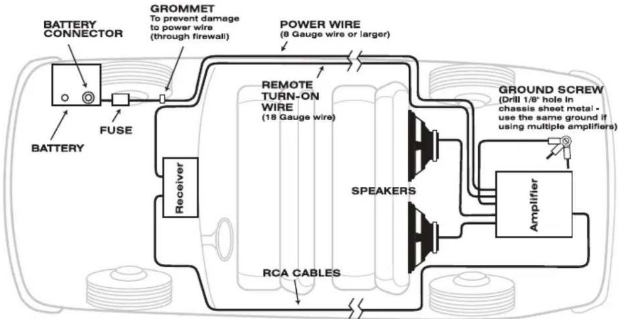
flowchart
graph TD
    A["BATTERY CONNECTOR"] --> B["FUSE"]
    B --> C["Receiver"]
    C --> D["RCA CABLES"]
    D --> E["SPEAKERS"]
    E --> F["AMPLIFIER"]
    F --> G["GROUND SCREW (Drill 1/8" hole in chassis sheet metal - use the same ground if using multiple amplifiers)"]
    H["GROMMET To prevent damage to power wire (through firewall)"] --> I["POWER WIRE (8 Gauge wire or larger)"]
    I --> J["REMOTE TURN-ON WIRE (18 Gauge wire)"]
    J --> K["Speaker"]
    L["BATTERY"] --> M["FUSE"]
LED STATUS INDICATOR
AMPLIFIER STATUS INDICATOR
POWER: The LED will illuminate in GREEN while amplifier is on.
POWER PROTECT: The LED will illuminate in RED to indicate the Amp is in "Protect Mode", This may be due to an overload or circuit problem (See page 7-8 for trouble shooting tips).
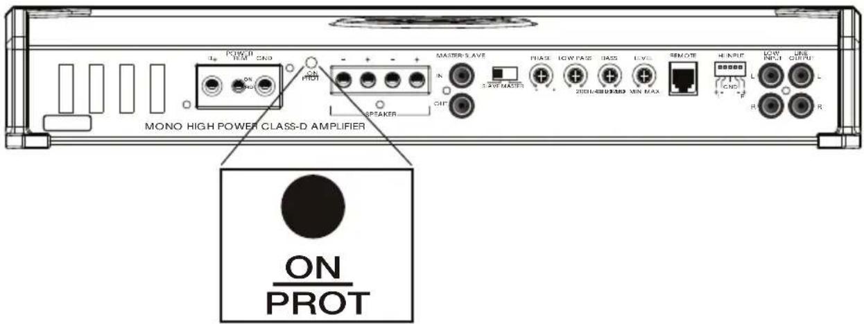
AMPLIFIER ADJUSTMENTS

Level:
The Level Adjust Control (Gain) matches the output of your Car Stereo to the inputs on the Amplifier.
-
Turn Stereo on and adjust the volume to about 3/4's of the stereo's maximum volume.
-
Carefully turn the Level control up (by turning it clockwise from the "Min" position) on the Amp until the sound is just above your normal listening volume or near distortion. (Distortion is when the sound/ music becomes garbled, breaks up, or unclear).
-
If there is excessive HUM or HISS between songs, the levels are set TOO HIGH and should be turned down, (reverse towards "Min").
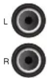
Low Level Inputs:
Low Level (RCA) inputs. Using the Low Level output from your car stereo is recommended (if available). If no Low Level Outputs are available from your car stereo, please see the HIGH LEVEL INPUT on page 6.
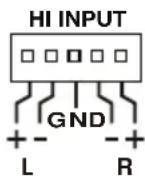
High Input Harness:
Use the High Level input harness if you are connecting your amplifier to a Factory Stereo or a Stereo that does not have any available Low-Level (RCA) outputs. Connect Left and Right Speaker outputs from the vehicle to the Left and Right High Level input wires.
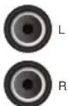
Low Level Outputs:
The Line Level Output is to be used as an easy solution to link multiple amplifiers together without the use of RCA Y-cables or running extra RCA cables from the front of the vehicle to the rear amplifier location.
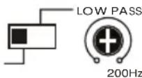
Low Pass Filter:
Use the Low Pass filter when you want to Filter out high frequencies.
Set the switch to Low Pass and adjust the level to the desired frequency.

Remote Level Control:
Plug the cable into the REM connector on the amplifier and into the controller. This will allow you to adjust the level of your amplifier while in low filter mode from the crossover frequency and below.

Bass Boost:
Adjustable Bass Boost (0\~ +12dB @ 45Hz)
Use Caution while adjusting Bass Boost. Using to high of a setting may cause distortion or damage Speakers.
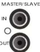
Master/ Slave In and Outputs:
The Master and Slave settings on the 1000c1 allow you to “Strap” or compound (2) amplifiers to a drive a Single voice coil based on your specific needs and power requirements. The default setting is for Master. If you choose to Slave a second amp, please see page 6.
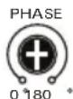
Phase Level:
Adjusts the relative phase of the output in a range of 0 to -180 degrees.
POWERING YOUR AMPLIFIER
PRELIMINARY: DISCONNECT THE NEGATIVE BATTERY TERMINAL TO AVOID SHORT CIRCUITS.
CAUTION: USE OF OTHER THAN SPECIFIC FUSES MAY DAMAGE SYSTEM OR VEHICLE. USE OF UNSPECIFIED FUSES WILL VOID WARRANTY.
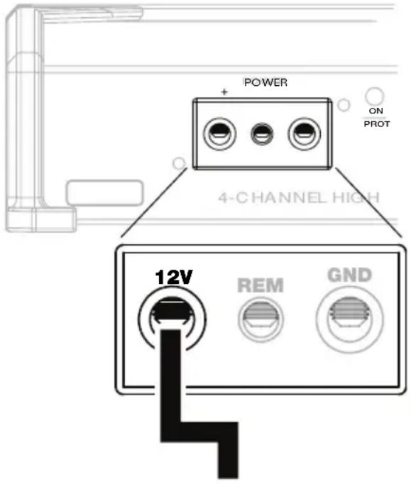
Fuses: Use only specified fuses (see note). NOTE: Use three 25A ATC fuses for 500c1, or use four 25A ATC fuses for 1000c1.
+12 Volts:
The High current lead for the amplifier must run directly to the positive battery terminal via a dedicated fuse block. Fuse should be mounted as close to positive battery terminal as possible. DO NOT CONNECT to cars fuse block or wires from car's stereo.
+ 12V Connection (+12V):
Connect to positive terminal of battery. Use proper gauge wire (4 gauge wire is recommended for the 500c1, 4 gauge is also recommended for the 1000c1.
AMPLIFIER WIRE GAUGE KIT
| MODEL | MAX CURRENT DRAW | 8 FEET | 15 FEET | 20 FEET |
| 500c1 | 75A | 8AWG | 8AWG | 4AWG |
| 1000c1 | 100A | 8AWG | 4AWG | 4AWG |
| wiring kits available atefxcaraudio.com | ||||
REMOTE TURN-ON
CAUTION: CONNECTION TO A (+12V) CONSTANT SOURCE MAY CAUSE CARS BATTERY TO DRAIN.
REM

natural_image
Pure geometric line drawing of a right angle with a circular top and base (no text or symbols)REMOTE TURN-ON (REM)
Allows the amplifier to be switched on remotely from the Car Stereo. Most aftermarket Car Stereo's have dedicated leads labeled REM or Remote Amp Turn-on. A +12 volt DC signal is required to turn-on the amplifier.
REMOTE TURN-ON CONNECTIONS (REM)
(Remote Amp Turn-on)
Connect to Car Stereo's Remote Amplifier Turn-on lead. If Car Stereo does not have a Remote Amplifier turn-on: Connect to the Power Antenna turn on or Car Stereo's Accessory wire. The Accessory wire will have 12 Volts while the Ignition is in the "ON/RUN" or "ACC" position and no voltage while ignition is off. If you use the power antenna wire, be sure Power antenna wire is active while CD/Cassette is playing.
GROUNDING YOUR AMPLIFIER
GND

natural_image
Pure mechanical diagram showing a screw and gear without any text or symbolsGROUND (GND)
The ground wire is a high current connection. This needs to connect to a clean chassis metal point on the vehicle. We recommend a using a star washer when securing your connection in the vehicle. The ground cable should be as close to amplifier as possible, no more than 3 feet from Amplifier.
SELF
TAPPING
SCREW
STAR WASHER
RING TERMINAL
NOTE: BE SURE THE SURFACE YOU ARE GROUNDING TO IS FREE OF PAINT, RUST, OR GREASE.
SPEAKER OUTPUTS
THE FOLLOWING ARE RECOMMENDATIONS ON HOW TO MAKE YOUR CONNECTIONS FOR 1-CHANNEL (MONO) CONFIGURATIONS
Speaker connections are used to connect the speakers to the amplifier. Be sure speakers with the appropriate *impedances are used. It is extremely important that the speaker wires are NOT connected to or touching the chassis (Ground) of the vehicle in any way.
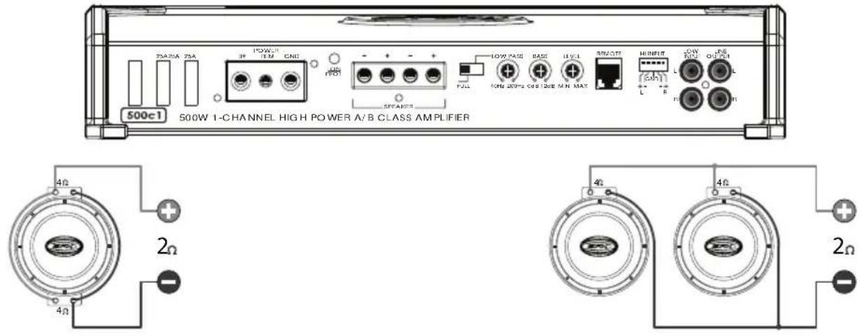
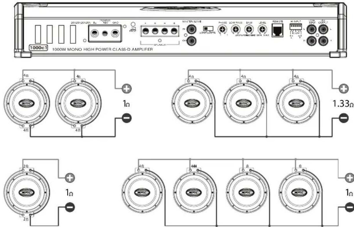
The EFX 500c1 and 1000c1 are MONO amplifiers. Though they have 2 positive and 2 negative terminals, they are the SAME output channel and are paralleled inside the amplifier.
1-CHANNEL (MONO) CONFIGURATIONS
500c1 - SPEAKER CONNECTIONS
1000c1 - SPEAKER CONNECTIONS
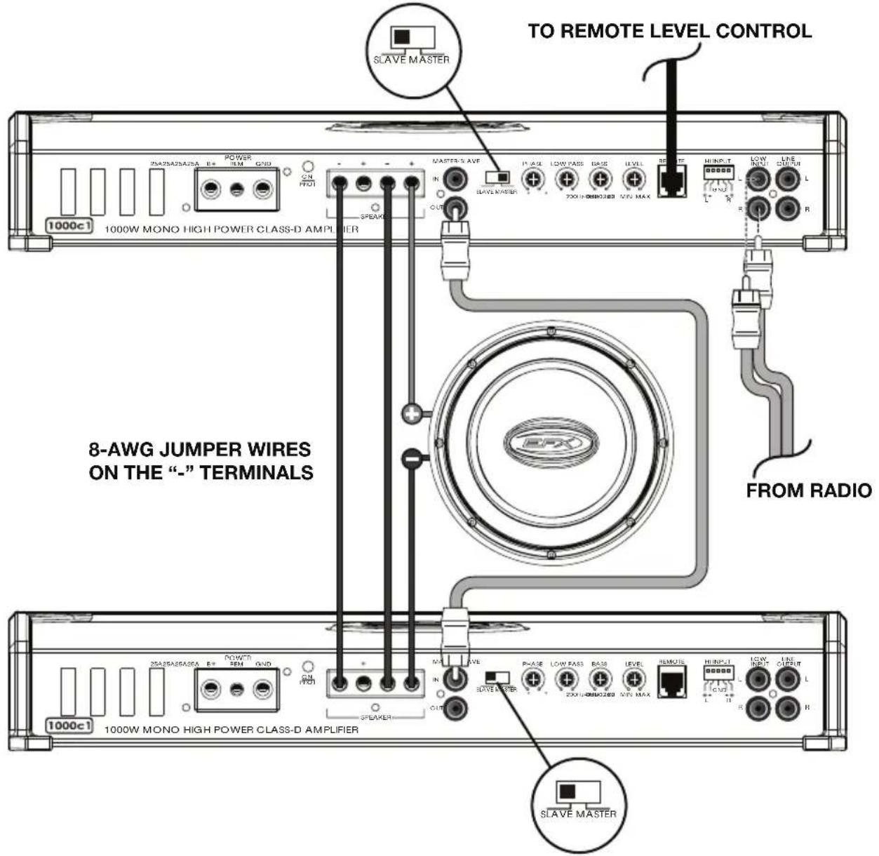
If you choose to Slave a second amp, then connect the "Master" audio output on the First amp to the Slave audio 'IN' on the Second amplifier. Set the switch on the 2nd Amplifier to the "Slave" position. Connect the Negative outputs between the amps with NO LESS than 8 AWG wire. Use the Positive (+) speaker out from the Master to the Positive Subwoofer terminal and use the Positive (+) Speaker out from the Slave amplifier to the Negative terminal of the SUB.
NOTE: When in Slave mode, all adjustments on Slave amp are by passed.
HIGH INPUT HARNESS
FOR HIGH LEVEL INPUT
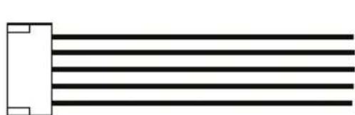
Simply splice the speaker outputs of your radio to the high input harness according to the color code chart below. For questions or concerns please contact our Tech Support Team at 1-800-6213695 Ex3.
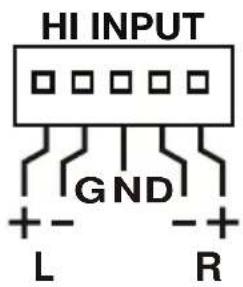
IMPORTANT: PLEASE WIRE YOUR STEREO'S SPEAKERS TO THE HIGH INPUT HARNESS USING THIS COLOR CODE CHART.
natural_image
Pure diagram of parallel lines with a rectangular base and corner markers (no text or symbols)| COLOR CODES | |
| GRAY = | Left Positive (+) |
| BROWN = | Left Negative (-) |
| BLACK = | Ground |
| GREEN = | Right Negative (-) |
| WHITE = | Right Positive (+) |
| TROUBLE SHOOTING | ||
| Amplifier will not turn on or No power power light not on. | No Voltage on +12V Input. | Use a volt meter to verify voltages at terminals of amplifiers +12V Inputs should have a minimum of 11.5 volts while ignition of vehicle is ON or OFF. |
| No Turn-On from Car Stereo | Use voltmeter to verify voltage at terminal of amplifiers REM input. REM input should have 12 volts while Car Stereo is "ON" and 0 volts While "OFF". | |
| Bad Connection at Battery or Fuse at Battery | Check main power connection and fuse at battery. | |
| Shorted Speaker line or connections. | Disconnect all speakers but not +12V, GND or REM lines - if unit then turns on, a speaker or speaker line may be touching vehicle chassis. Check Speakers and speaker lines for shorts. | |
| Power but no sound. (Indicator is GREEN) | Bad connection on RCA plugs or speakers are not connected correctly. | Check Low level (RCA) connections. Be sure they are connected at Car Stereo and amplifier. Check all Speaker output connections. |
| Speakers wrong impedance over loading amplifier. | Disconnect Speaker from Amplifier. Verify speaker impedances. For Stereo/2-channel mode speakers should be 2ohm or 4ohm each. For Bridged mode speaker(s) should be no less than 4ohms. Speaker impedances can be found by checking speaker manufacturer specification or using a Digital Volt/Ohm meter. If you need further assistance please call 800-621-3695x3. | |
| No sound from one channel or entire side. | Car Stereo's balance and fader controls set incorrectly. | Check Car Stereo's balance and fader control positions - verify they are centered. |
| Bad Connection at Amplifier or Speaker. | Check speaker connections at amplifier and speaker. | |
| Bad Input Via RCA or Hi level inputs. | Check all input leads at amplifier. Be sure RCA's are connected to Car Stereo and amplifier. Check High level inputs for connection to amp verify connections. | |
| Input Switch in the wrong position. | Check input switch position and retest. | |
| Very low sound level. | Car Stereo's balance and fader controls set incorrectly. | Check Car Stereo's balance and fader control positions - verify they are centered. |
| Amplifier's input gain control setting is not correct. | Check amplifier's input gain control settings - adjust levels if necessary. | |
| Power amplifier turns on and off repeatedly. | Low Voltage on +12V Inputor Connections at Battery. | Check +12V connections at the battery and amplifier inputs. |
| Low vehicle Battery Voltage. | Verify battery voltage. Voltage should be greater than 11.5 volts DC at amplifier with engine off. | |
| Bad Connection on Car Stereo or Amplifier. | Check Car Stereo and amplifier's ground connections. | |
MORE TIPS ON PAGE 8
| TROUBLE SHOOTING | ||
| Amplifier turns off during loud or distorted passages or Protection Light comes On. | Amplifier's input gain control may be set too high or settings not correct. | Check amplifier's input gain control settings - adjust levels if necessary. |
| Low vehicle battery voltage. | Verify battery voltage is greater than 11.5v DC at amplifier with engine off. | |
| Bad connection on car stereo or Amplifier | Check Car Stereo and amplifier's ground connections. | |
| Wrong speaker impedances. | Disconnect Speaker from Amplifier. Verify speaker impedances. For Stereo/2-channel mode speakers should be 2 or 4 ohms each. For Bridged mode speaker(s) should be no less than 4ohms. Speaker impedances can be found by checking speaker manufacturer specification or using a Digital Volt/Ohm meter. If you need further assistance with this please call 1-800-621-3695 x3. | |
| Amplifier operates. But gets very hot. | Input gain control too high | Lower gain control |
| Wrong Speaker impedances. | Disconnect speaker from Amplifier. Verify speaker impedances. For Stereo/2-channel mode speakers should be 2 or 4 ohms each. For Bridged mode speaker(s) should be no less than 4ohms. Speaker impedances can be found by checking speaker manufacturer specification or using a DigitalVolt/Ohm meter. If you need further assistance with this please call 1-800-621-3695 x3. | |
| Not enough air circulation around amplifier. Amplifier is covered by Carpet or other material. | Verify mounting location allows free air circulation around amplifier. | |

EFX Audio is a division of Scosche Industries Inc. 2009, visit us at www.efxcaraudio.com
LIMITED WARRANTY
EFX Audio warrants this product to be free from defects in material and workmanship, for a period of 1 year from purchase. This EFX Audio product is sold with the understanding that the purchaser has independently determined the suitability of this product. This warranty DOES NOT cover any expenses incurred from the installation, removal, or re-installation of this product incidental or otherwise. This warranty is offered to the original purchaser of the product only. This warranty does not cover the product if physically damaged, subjected to negligence or misuse, abuse, improper installation, alteration, accident, connection to improper WATTAGE amounts, or an act of God. Also excluded from this warranty are costs for the correction of faulty installation, and elimination of electromagnetic interference. (Engine noise) The original dated sales slip or proof of purchase will establish warranty eligibility. If the product should prove defective, within the warranty period, return the product with proof of purchase to EFX Audio, EFX Audio at its option, will replace or repair the product free of charge, and return the product postage-paid. In no event shall EFX Audio, can not be responsible for claims beyond the replacement value of the defective product, or in any way be liable or responsible for consequential or incidental damages. No express warranties and no implied warranties whether for fitness or any particular use, or otherwise, except as set forth above (which is made expressly in lieu of all other warranties) shall apply to products. EFX Audio can not be held responsible for discrepancies/inconsistencies that may occur, due to automotive manufacturing changes or options.

- 1-CHANNEL (MONO) AMPLIFIERS INSTALLATION MANUAL
- EFX AMPLIFIER FEATURES
- 500c1
- 1000c1
- IMPORTANT/ PRELIMINARY
- BEFORE YOU BEGIN:
- Installation procedures:
- Tools & Supplies
- Location/Mounting Amplifier
- ROUTING CABLES AND WIRES
- LED STATUS INDICATOR
- AMPLIFIER STATUS INDICATOR
- AMPLIFIER ADJUSTMENTS
- Level:
- Low Level Inputs:
- High Input Harness:
- Low Level Outputs:
- Low Pass Filter:
- Remote Level Control:
- Bass Boost:
- Master/ Slave In and Outputs:
- Phase Level:
- POWERING YOUR AMPLIFIER
- PRELIMINARY: DISCONNECT THE NEGATIVE BATTERY TERMINAL TO AVOID SHORT CIRCUITS.
- +12 Volts:
- + 12V Connection (+12V):
- REMOTE TURN-ON
- REMOTE TURN-ON (REM)
- REMOTE TURN-ON CONNECTIONS (REM)
- GROUNDING YOUR AMPLIFIER
- GROUND (GND)
- SPEAKER OUTPUTS
- THE FOLLOWING ARE RECOMMENDATIONS ON HOW TO MAKE YOUR CONNECTIONS FOR 1-CHANNEL (MONO) CONFIGURATIONS
- 1-CHANNEL (MONO) CONFIGURATIONS
- HIGH INPUT HARNESS
- FOR HIGH LEVEL INPUT
- MORE TIPS ON PAGE 8
- LIMITED WARRANTY
Brand : Scosche
Model : EFX Mono Amplifier
Category : Receiver