
MC-126 - Audio Receiver MCINTOSH - Free user manual and instructions
Find the device manual for free MC-126 MCINTOSH in PDF.


| Product Type | Audio Receiver |
| Brand | McIntosh |
| Model | MC-126 |
| Dimensions (W x H x D) | 17.5 x 5.5 x 16 inches (44.5 x 14 x 40.6 cm) |
| Weight | 42 lbs (19 kg) |
| Power Output (per channel) | 100 watts RMS into 8 ohms |
| Frequency Response | 20 Hz - 20 kHz ±0.5 dB |
| Total Harmonic Distortion | < 0.05% |
| Signal-to-Noise Ratio | 90 dB |
| Input Sensitivity (Phono) | 2.5 mV |
| Input Sensitivity (Line) | 200 mV |
| Speaker Impedance | 4 to 8 ohms |
| Tuner Bands | AM / FM |
| Audio Inputs | Phono, Aux, Tape, CD, Tuner |
| Audio Outputs | Speaker A/B, Headphone, Tape |
| Power Consumption | 350 watts max |
| Power Supply | 120V, 60 Hz (AC) |
| Maintenance | Clean with soft dry cloth; avoid liquids |
| Safety | Use grounded outlet; keep ventilation clear |
| Spare Parts and Repairability | Authorized service centers; genuine McIntosh parts |
Frequently Asked Questions - MC-126 MCINTOSH
User questions about MC-126 MCINTOSH
0 question about this device. Answer the ones you know or ask your own.
Ask a new question about this device
Download the instructions for your Audio Receiver in PDF format for free! Find your manual MC-126 - MCINTOSH and take your electronic device back in hand. On this page are published all the documents necessary for the use of your device. MC-126 by MCINTOSH.
USER MANUAL MC-126 MCINTOSH
MC126 Power Amplifier
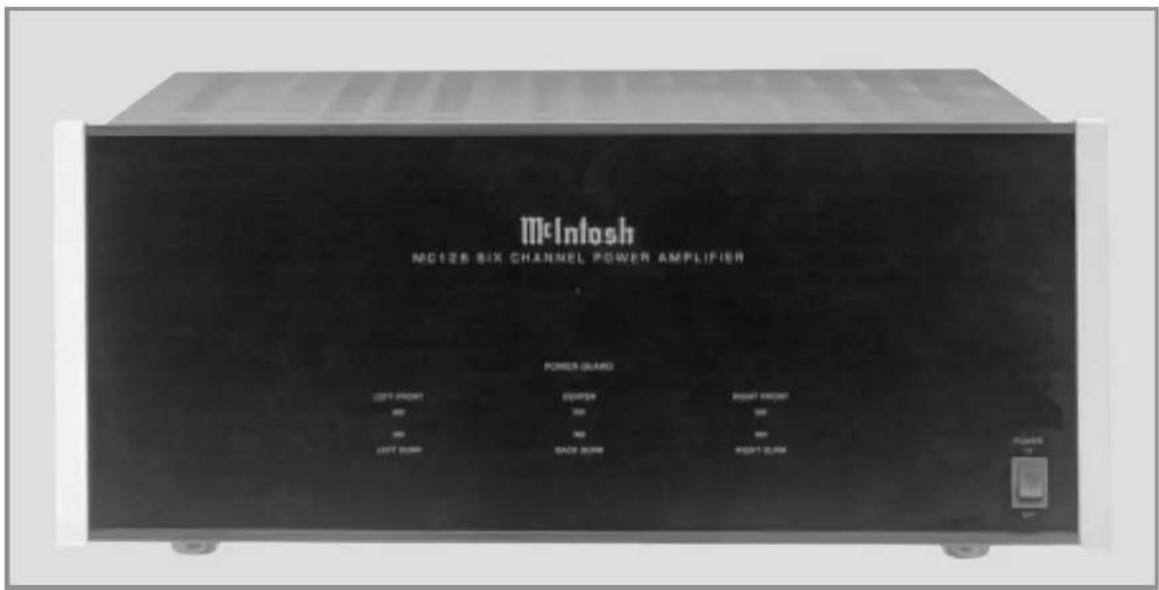
MC126
The lightning flash with arrowhead, within an equilateral triangle, is intended to alert the user to the presence of uninsulated “dangerous voltage” within the product’s enclosure that may be of sufficient magnitude to constitute a risk of electric shock to persons.

AVIS RISQUE DE CHOC ELECTRIQUE - NE PAS OUVRIR.
The exclamation point within an equilateral triangle is intended to alert the user to the presence of important operating and maintenance (servicing) instructions in the literature accompanying the appliance.
WARNING - TO REDUCE RISK OF FIRE OR ELECTRICAL SHOCK, DO NOT EXPOSE THIS EQUIPMENT TO RAIN OR MOISTURE.
NO USER-SERVICEABLE PARTS INSIDE. REFER SERVICING TO QUALIFIED PERSONNEL.
To prevent the risk of electric shock, do not remove cover or back. No user serviceable parts inside.
IMPORTANT SAFETY INSTRUCTIONS!
PLEASE READ THEM BEFORE OPERATING THIS EQUIPMENT.
General:
- Read these instructions.
- Keep these instructions.
- Heed all warnings.
- Follow all instructions.
-
Warning: To reduce risk of fire or electrical shock, do not expose this equipment to rain or moisture. This unit is capable of producing high sound pressure levels. Continued exposure to high sound pressure levels can cause permanent hearing impairment or loss. User caution is advised and ear protection is recommended when playing at high volumes.
-
Caution: to prevent electrical shock do not use this (polarized) plug with an extension cord, receptacle or other outlet unless the blades can be fully inserted to prevent blade exposure.
-
Unplug this equipment during lightning storms or when unused for long periods of time.
-
Only use attachments/accessories specified by the manufacturer.
Installation:
- The equipment shall be installed near the AC Socket Outlet and the disconnect device shall be easily accessible.
- Do not block any ventilation openings. Install in accordance with the manufacturer's instructions.
- Do not install near any heat sources such as radiators, heat registers, stoves, or other equipment (including amplifiers) that produce heat.
- Do not use this equipment near water.
- Do not expose this equipment to dripping or splashing and ensure that no objects filled with liquids, such as vases, are placed on the equipment.
- Use only with the cart, stand, tripod, bracket, or table specified by the manufacturer, or sold with the equipment. When a cart is used, use caution when moving the cart/equipment combination to avoid injury from tip-over.

Connection:
- Connect this equipment only to the type of AC power source as marked on the unit.
- Protect the power cord from being walked on or pinched particularly at plugs, convenience receptacles, and the point where they exit from the equipment.
- Do not defeat the safety purpose of the polarized or grounding-type plug.
A polarized plug has two blades with one wider than the other. A grounding type plug has two blades and a third grounding prong. The wide blade or the third prong are provided for your safety. If the provided plug does not fit into your outlet, consult an electrician for replacement of the obsolete outlet.
- Do not overload wall outlets, extension cords or integral convenience receptacles as this can result in a risk of fire or electric shock.
- To completely disconnect this equipment from the AC Mains, disconnect the power supply cord plug from the AC receptacle.
Care of Equipment:
- Clean only with a dry cloth.
- Do not permit objects or liquids of any kind to be pushed, spilled and/or fall into the equipment through enclosure openings.
- Unplug the power cord from the AC power outlet when left unused for a long period of time.
Repair of Equipment:
- Refer all servicing to qualified service personnel. Servicing is required when the equipment has been damaged in any way, such as power-supply cord or plug is damaged, liquid has been spilled or objects have fallen into the equipment, the equipment has been exposed to rain or moisture, does not operate normally, or has been dropped.
- Do not attempt to service beyond that described in the operating instructions. All other service should be referred to qualified service personnel.
- When replacement parts are required, be sure the service technician has used replacement parts specified by McIntosh or have the same characteristics as the original part. Unauthorized substitutions may result in fire, electric shock, or other hazards.
- Upon completion of any service or repairs to this product, ask the service technician to perform safety checks to determine that the product is in proper operating condition.
Thank You
Your decision to own this McIntosh MC126 Power Amplifier ranks you at the very top among discriminating music listeners. You now have “The Best.” The McIntosh dedication to “Quality,” is assurance that you will receive many years of musical enjoyment from this unit.
Please take a short time to read the information in this manual. We want you to be as familiar as possible with all the features and functions of your new McIntosh.
Please Take A Moment
The serial number, purchase date and McIntosh dealer name are important to you for possible insurance claim or future service. The spaces below have been provided for you to record that information:
Serial Number: ____
Purchase Date: ____
Dealer Name: ____
Technical Assistance
If at any time you have questions about your McIntosh product, contact your McIntosh dealer who is familiar with your McIntosh equipment and any other brands that may be part of your system. If you or your dealer wish additional help concerning a suspected problem, you can receive technical assistance for all McIntosh products at:
McIntosh Laboratory, Inc.
2 Chambers Street
Binghamton, New York 13903
Phone: 607-723-1545
Fax: 607-723-3636
Customer Service
If it is determined that your McIntosh product is in need of repair, you can return it to your dealer. You can also return it to the McIntosh Laboratory Service Department. For assistance on factory repair return procedure, contact the McIntosh Service Department at:
McIntosh Laboratory, Inc.
2 Chambers Street
Binghamton, New York 13903
Phone: 607-723-3515
Fax: 607-723-1917
Copyright 2001 © by McIntosh Laboratory, Inc.
Table of Contents
| Safety Instructions | 2 |
| Thank You and Please Take a Moment | 3 |
| Technical Assistance and Customer Service | 3 |
| Table of Contents and General Notes | 4 |
| Introduction | 4 |
| Performance Features | 4 |
| Dimensions | 5 |
| Installation | 6 |
| Rear Panel Connections and Switch | 7 |
| How to Connect for Six Channels | 8 |
| How to Connect for Three Channels | 10 |
| Front Panel Displays and Controls | 12 |
| How to Operate | 13 |
| Specifications | 14 |
| Packing Instruction | 15 |
General Notes
- The following Connecting Cable is available from the McIntosh Parts Department:
Power Control Cable Part No. 170-202
Six foot, 2 conductor shielded, with two 1/8 inch stereo mini phone plugs. - For additional connection information, refer to the owner's manual(s) for any component(s) connected to the MC126.
- The MC126 mutes the speaker outputs for approximately two seconds when first turned on.
- It is very important that loudspeaker cables of adequate size be used, so that there will be no power loss. The size is specified in Gauge Numbers or AWG, (American Wire Gauge). The smaller the Gauge number, the larger the wire size. The MC126 Loudspeaker Connection Terminals will accept up to a 10 AWG wire size:
If your loudspeaker cables are 50 feet (38.1m) or less, use at least 14 Gauge.
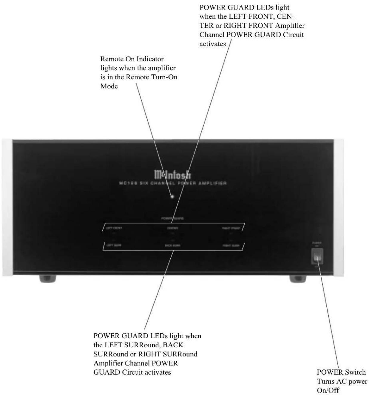
If your loudspeaker cables are 100 feet (76.2m) or less, use at least 12 Gauge. - In the event that the MC126 over heats, due to improper ventilation and/or high ambient temperature, the protection circuits will activate. The Front Panel Power Guard LEDs will continuously indicate ON and the audio will be muted. When the MC126 has returned to a safe operating temperature, normal operation will resume.
- The Multi-Channel Input DB25 Connector allows for easy connecting of a McIntosh MX130/132 or C39 A/V Control Center, Audio and Power Control connections, to the MC126. If a McIntosh MSE1 Surround Expander is connected to the MX130/132 or C39, then discrete Audio and Power Control Cables should be used between them and the MC126. The Diagram and Pin Identification list for the Multi-Channel
Input is as follows:
Multi-Channel Input

Multi-Channel Amp DB25 Connector Pin Layout
- Left Front + 14. Left Front Gnd.
- Center Front + 15. Center Front Gnd.
- Right Front + 16. Right Front Gnd.
- N/C 17. N/C
- Left Surround + 18. Left Surround Gnd.
- Right Surround + 19. Right Surround Gnd.
- Left Back Surround + 20. Left Back Surround Gnd.
- Right Back Surround + 21. Right Back Surround Gnd.
- N/C 22. N/C
- N/C 23. N/C
- N/C 24. System Calibrate Gnd.
- System Calibrate 25. Power Control Gnd.
- Power Control In
Introduction
Now you can take advantage of traditional McIntosh standards of excellence in the MC126 Power Amplifier. Six 120 watt high current output channels will drive any high quality loudspeaker system to its ultimate performance. The MC126 reproduction is sonically transparent and absolutely accurate. The McIntosh Sound is “The Sound of the Music Itself.”
Performance Features
●Power Output
The MC126 consists of six separate power amplifier channels, each capable of 120 watts into 4 ohm speakers with less than 0.005% distortion. It may also be used as a Three Channel Amplifier with each channel capable of 275 watts into 8 ohm speakers.
●High Current Output
A peak output current of 10 amperes per channel ensures that the MC126 will successfully drive high quality loudspeakers such as McIntosh for a truly exciting sound experience.
●Power Guard
The MC126's Patented McIntosh Power Guard Circuits prevent each of the amplifier channels from being overdriven into clipping, with its harsh distorted sound that can also damage your valuable loudspeakers.
- Sentry Monitor and Thermal Protection
McIntosh Sentry Monitor power output stage protection circuits ensure the MC126 will have a long and trouble free operating life. Built-in Thermal Protection Circuits guard against overheating.
Dimensions
The following dimensions can assist in determining the best location for your MC126. There is additional information on the next page pertaining to installing the MC126 into cabinets.

Installation
The MC126 can be placed upright on a table or shelf, standing on its four feet. It also can be custom installed in a piece of furniture or cabinet of your choice. The four feet may be removed from the bottom of the MC126 when it is custom installed as outlined below. The four feet together with the mounting screws should be retained for possible future use if the MC126 is removed from the custom installation and used free standing. It also can be custom installed in a piece of furniture or cabinet of your choice The required panel cutout, ventilation cutout and unit dimensions are shown.
Always provide adequate ventilation for your MC126. Cool operation ensures the longest possible operating life for any electronic instrument. Do not install the MC126 directly above a heat generating component such as a high powered amplifier. If all the components are installed in a single cabinet, a quiet running ventilation fan can be a definite asset in maintaining all the system components at the coolest possible operating temperature.
A custom cabinet installation should provide the following minimum spacing dimensions for cool operation. Allow at least 6 inches (15.24 cm) above the top, 2 inches (3.81cm) below the bottom and 1 inch (2.54 cm) on each side of the amplifier, so that airflow is not obstructed. Allow 20 inches (50.8 cm) depth behind the front panel. Allow 1 inch (2.54 cm) in front of the mounting panel for knob clearance. Be sure to cut out a ventilation hole in the mounting shelf according to the dimensions in the drawing.
MC126 Front Panel
Custom Cabinet Cutout
MC126 Side View in Custom Cabinet
MC126 Bottom View in Custom Cabinet


How to Connect the MC126 for Six Channels
Caution: The supplied AC Power Cord should not be connected to the Rear Panel of the MC126 Amplifier until after the Loudspeaker Connections have been made and the supplied protective Terminal Connection Covers have been installed. Failure to observe this could result in Electric Shock.
- Connect a power control cable from the McIntosh A/V Control Center Power Control Out to the McIntosh Surround Expander Power Control In.
- Connect a power control cable from the McIntosh Surround Expander Power Control Out to the MC126 POWER CONTROL IN.
-
Connect cables from the Audio Outputs of a McIntosh A/V Control Center and Surround Expander to the MC126 INPUTS, making sure to match up the channel identifications between both units.
-
Prepare the Loudspeaker Hookup Cables that attach to the MC126 Power Amplifier by choosing one of the methods below:
Bare wire cable ends:
Carefully remove sufficient insulation from the cable ends, refer to

strands together as tightly as possible.
Note: If desired, the twisted ends can be tinned with solder to keep the strands together, or attach spade lug and/or banana connector.
Spade lug or prepared wire connection:
Insert the spade lug connector or prepared section of the cable end into the terminal side access hole, and tighten the terminal cap until the cable is firmly
clamped into the terminal so the wires cannot slip out. Refer to
figures 4, 5 & 6.


Banana plug connection:
Insert the banana plug into the hole at the top of the terminal. Tighten the top portion of the terminal post and the set screw to secure the banana plug in place.
Note: The use of Banana Plugs is for use in the United States and Canada only.
- Connect the Loudspeaker Hookup Cables from the MC126 OUTPUT Terminals to the loudspeakers, being careful to observe the correct polarities and channel designation.
WARNING: Loudspeaker terminals are hazardous live and present a risk of electric shock. For additional instruction on making Loudspeaker Connections contact your McIntosh Dealer or McIntosh Technical Support.
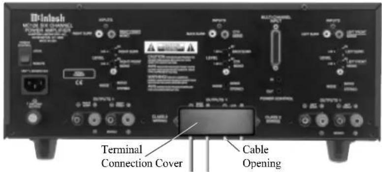
- Attach each of the three supplied Terminal Connection Covers with the four Pan Head Mounting Screws (6-32 x 5/16 inch) to the Rear Panel of the MC126 Amplifier. Refer to figures 7 and 8.

natural_image
Isometric line drawing of a mechanical or electronic device with multiple cylindrical components and a rectangular base (no text or symbols)Figure 7
Note: There are four openings on the bottom edge of the cover to allow the Loudspeaker Cables to exit the MC126.
- Connect the MC126 Power Cord to an active AC outlet.
Figure 8

How to Connect the MC126 for Three Channels
Caution: The supplied AC Power Cord should not be connected to the Rear Panel of the MC126 Amplifier until after the Loudspeaker Connections have been made and the supplied protective Terminal Connection Covers have been installed. Failure to observe this could result in Electric Shock.
- Connect a power control cable from the McIntosh A/V Control Center Power Control Out to the McIntosh MC126 POWER CONTROL IN.
- Connect cables from the Audio Outputs of a McIntosh A/V Control Center to the MC126 MONO INPUTS.
- Prepare the Loudspeaker Hookup Cables that attach to the MC126 Power Amplifier by choosing one of the methods below:
Bare wire cable ends:
Carefully remove sufficient insulation from the cable
ends, refer to figures 1, 2 & 3. If the cable is stranded, carefully twist the strands to-
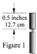
Figure 2

Figure 3

gether as tightly as possible.
Note: If desired, the twisted ends can be tinned with solder to keep the strands together, or attach spade lug and/or banana connector.
Spade lug or prepared wire connection:
Insert the spade lug connector or prepared section of the cable end into the terminal side access hole, and tighten
the terminal cap until the cable is firmly clamped


into the terminal so the wires cannot slip out. Refer to figures 4, 5 & 6.
Banana plug connection:
Insert the banana plug into the hole at the top of the terminal. Tighten the top portion of the terminal post and the set screw to secure the banana plug in place.
Note: The use of Banana Plugs s for use in the United States and Canada only.
- Connect the Loudspeaker Hookup Cables from the MC126 MONO OUTPUT Terminals to the loudspeakers, being careful to observe the correct polarities and channel designation.
WARNING: Loudspeaker terminals are hazardous live and present a risk of electric shock. For additional instruction on making Loudspeaker Connections contact your McIntosh Dealer or McIntosh Technical Support.
- Attach each of the three supplied Terminal Connection
Covers with the four Pan Head Mounting Screws (6-32 x 5/16 inch) to the Rear Panel of the MC126 Amplifier. Refer to figures 7 and 8.
Note: There are four openings on the bottom edge of the cover to allow the Loudspeaker Cables to ex

natural_image
Isometric line drawing of a device with three cylindrical ports and a rectangular base (no text or symbols)Figure 7
- Connect the MC126 Power Cord to an active AC outlet.
Figure 8


How to Operate the MC126
Power On
To have the MC126 turn On or Off when a multichannel system turns On or Off, the Front Panel Power Switch must be left in the ON position and the Rear Panel Power Control Switch must be in the REMOTE Position. For non-remote operation, set the Rear Panel Power Control Switch to LOCAL and use the Front Panel Power Switch to turn the MC126 On or Off as desired. Refer to figure 9.

Figure 9
Note: There must be a power control connection between the MC126 and the McIntosh A/V Control Center or Surround Decoder in order for the remote power turn-on to function.
Input Level Controls
When using a McIntosh A/V Control Control Center or Surround Decoder set all six level controls to the 1.6V position. If an A/V Control Center or Surround Decoder has a 0.8V output rating, set the controls to the 0.8V position. If an increase or decrease in amplifier sensitivity is required for other applications, set the controls as desired. Refer to figure 10.

Figure 10
Mode Switch
The MODE Switch allows a pair of MC126 channels to be used in two different operating configurations. Refer to figure 11.
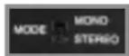
Figure 11
Stereo: Each channel operates independently as 120 watt amplifiers.
Mono: A channel pair operates in bridged configuration for a single monaural 275 watt amplifier.
How to Operate with a Bridged Channel
The versatile McIntosh MC126 can be used in two different Operating Modes. The three channel pairs can be used in Stereo Mode to supply 120 watts (4 ohm) to each of the Home Theater System's six channels. Any of the three stereo pairs can be set to Mono (Bridged) Mode to supply 275 watts (8ohm) of power when greater power is desired. Refer to figures 10, 11 and 12.
- Set the MODE Switch to the MONO position.
- Adjust the MONO Level control to the 1.6V position if using a McIntosh A/V Control Center or
- Connect the cable from the signal source component to the MONO In jack.
- Connect loudspeaker cables to the terminals marked (-) and (+) MONO.

Figure 12
Specifications
Power Output Stereo
Minimum sine wave continuous average power output per channel, all channels operating is:
120 watts into a 4 ohm load
80 watts into a 8 ohm load
Power Output Mono
Minimum sine wave continuous average power output per channel, all channels operating is:
275 watts into a 8 ohm load
Rated Power Band
20Hz to 20,000Hz
Total Harmonic Distortion
Maximum Total Harmonic Distortion at any power level from 250 milliwatts to rated power output is:
0.005% for 4 or 8 ohm loads (Stereo)
0.005% for 8 ohm loads (Mono)
Dynamic Headroom
1.8dB
Frequency Response
+0, -0.25dB from 20Hz to 20,000Hz
+0, -3dB from 10Hz to 100,000Hz
Sensitivity
0.8Volts
A-Weighted Signal To Noise Ratio
92dB (113dB below rated output)
Intermodulation Distortion
Maximum Intermodulation Distortion if instantaneous peak output per channel does not exceed twice the rated output, for any combination of frequencies from 20Hz to 20,000Hz, with all channels operating is:
0.005% for 4 or 8 ohm loads (Stereo)
0.005% for 8 ohm loads (Mono)
Input Impedance
20,000 ohms
Wide Band Damping Factor
100 at 4 ohms
200 at 8 ohms
Power Requirements
100 Volts, 50/60Hz at 9.4 amps
110 Volts, 50/60Hz at 8.5 amps
120 Volts, 50/60Hz at 5.9 amps
220 Volts, 50/60Hz at 4.3 amps
230 Volts, 50/60Hz at 4.0 amps
240 Volts, 50/60Hz at 3.9 amps
Note: Refer to the rear panel of the MC126 for the correct voltage.
Dimensions
Front Panel: 17-1/2 inches (44.45cm) wide, 7-1/8 inches (18.10cm) high. Depth behind front mounting panel is 18 inches (45.72cm). Clearance required in front of the Front Panel is 1 inch (2.54cm) for knobs.
Weight
58 pounds (26.3 kg) net, 77 pounds (34.9 kg) in shipping carton
Packing Instructions
In the event it is necessary to repack the equipment for shipment, the equipment must be packed exactly as shown below. It is very important that the three plastic feet are attached to the bottom of the equipment. Three #10 x 2-1/2 inch screws and washers must be used to fasten the unit securely to the bottom pad and wood skid. This will ensure the proper equipment location on the bottom pad. Failure to do this will result in shipping damage.
Use the original shipping carton and interior parts only if they are all in good serviceable condition. If a shipping carton or any of the interior part(s) are needed, please call or write Customer Service Department of McIntosh Laboratory. Please see the Part List for the correct part numbers.
Quantity Part Number Description
| 1 033888 Shipping carton only | ||||
| 4 033887 End cap (Foam pad) | ||||
| 1 033697 Inside carton only | ||||
| 1 033725 Top Pad | ||||
| 1 | 034008 | Bottom | pad | |
| 3 | 017218 | Plastic | foot | (spacer) |
| 1 033699 Shipping skid | ||||
| 3 101169 #10 x 2-1/2 inch Wood screw | ||||
| 3 104033 #10 x 1-3/4 inch Flat washer | ||||
| 4 | 017218 | Plastic | foot | |
| 4 100159 #10-32 x 3/4 inch Machine screw | ||||
| 4 104083 #10 x 7/16 inch Flat washer | ||||

McIntosh®
McIntosh Laboratory, Inc.
2 Chambers Street
Binghamton, NY 13903

- WARNING - TO REDUCE RISK OF FIRE OR ELECTRICAL SHOCK, DO NOT EXPOSE THIS EQUIPMENT TO RAIN OR MOISTURE.
- NO USER-SERVICEABLE PARTS INSIDE. REFER SERVICING TO QUALIFIED PERSONNEL.
- IMPORTANT SAFETY INSTRUCTIONS!
- PLEASE READ THEM BEFORE OPERATING THIS EQUIPMENT.
- General:
- Installation:
- Connection:
- Care of Equipment:
- Repair of Equipment:
- Thank You
- Please Take A Moment
- Technical Assistance
- Customer Service
- General Notes
- Multi-Channel Amp DB25 Connector Pin Layout
- Introduction
- Performance Features
- ●Power Output
- ●High Current Output
- ●Power Guard
- - Sentry Monitor and Thermal Protection
- Dimensions
- Installation
- How to Connect the MC126 for Six Channels
- How to Connect the MC126 for Three Channels
- Bare wire cable ends:
- Spade lug or prepared wire connection:
- Banana plug connection:
- How to Operate the MC126
- Power On
- Input Level Controls
- Mode Switch
- How to Operate with a Bridged Channel
- Specifications
- Power Output Stereo
- Power Output Mono
- Rated Power Band
- Total Harmonic Distortion
- Dynamic Headroom
- Frequency Response
- Sensitivity
- A-Weighted Signal To Noise Ratio
- Intermodulation Distortion
- Input Impedance
- Wide Band Damping Factor
- Power Requirements
- Weight
- Packing Instructions
- McIntosh®
Brand : MCINTOSH
Model : MC-126
Category : Audio Receiver