PL3200 - Receiver Citronic - Free user manual and instructions
Find the device manual for free PL3200 Citronic in PDF.


| Product Type | Professional Power Amplifier |
| Brand | Citronic |
| Model | PL3200 |
| Output Circuit Architecture | Class H, 2-step |
| RMS Power Output @ 4Ω | 2 x 1600W |
| RMS Power Output @ 8Ω | 2 x 915W |
| Bridge Power Output @ 8Ω | 3200W |
| Frequency Response | 5Hz – 50kHz |
| Signal-to-Noise Ratio | >111dB |
| Total Harmonic Distortion (THD) | 0.05% |
| Input Impedance | 20kΩ |
| Power Supply | 230V AC, 50/60Hz (IEC, 15A max.) |
| Dimensions (H x W x D) | 88 x 483 x 389mm |
| Weight | 10.5kg |
| Cooling | Dual fan cooling |
| Operating Modes | Stereo, Parallel, Bridge Mono |
| Protection Features | Short-circuit, DC, overload, soft-start, independent clip limiters |
| High Pass Filters | Selectable 30Hz or 50Hz per channel |
| Input Connections | Combo XLR/6.3mm jack (balanced) |
| Output Connections | Binding posts for CH1, CH2, and Bridge |
| Line Outputs | XLR (for daisy-chaining) |
| Ground Lift Switch | Disconnects signal ground from mains ground to reduce hum |
| Recommended Cleaning | Soft cloth with neutral detergent; vacuum vent grilles |
| Safety Note | No user-serviceable parts inside; refer to qualified personnel |
Frequently Asked Questions - PL3200 Citronic
User questions about PL3200 Citronic
0 question about this device. Answer the ones you know or ask your own.
Ask a new question about this device
Download the instructions for your Receiver in PDF format for free! Find your manual PL3200 - Citronic and take your electronic device back in hand. On this page are published all the documents necessary for the use of your device. PL3200 by Citronic.
USER MANUAL PL3200 Citronic
natural_image
Front view of two black Citronic audio equipment units (PL3200 and PL3800) with labeled buttons and ventilation grilles (no readable text beyond labels)Features:
• Class H, 2-step architecture
- Compact and light weight
• High efficiency, high output
- Independent dual-level clip limiters
- Independent dual-level high-pass filters
- Stereo, Parallel or Bridge Mono modes
• Fully balanced signal path
- Dual fan cooling
- Soft-start on power up
- Multi-level system protection
Introduction:
Thank you for choosing this Citronic Powerlite amplifier. This product has been designed to exacting standards to provide accurate, immediate high power on demand whilst remaining very lightweight and compact for easy portability. The class H architecture and innate protection circuitry are designed to provide reliable service for many years. Please, however, read and follow these instructions to attain the best performance from this amplifier and avoid mis-use through incorrect operation.
Warning:
To prevent the risk of fire or electric shock, do not expose any of the components to rain or moisture. If liquids are spilled on the casing, stop using immediately, allow unit to dry out and have checked by qualified personnel before further use.
Avoid impact, extreme pressure or heavy vibration to the case
No user serviceable parts inside – Do not open the case – refer all servicing to qualified service personnel.
Safety
- Check for correct mains voltage and condition of IEC lead before connecting to power outlet.
- Ensure speaker leads are good condition with no short connections or damaged plugs
- Check impedance of speaker loads do not exceed the minimum stated load for the amplifier
- Do not allow any foreign objects to enter the case or through the ventilation grilles.
Placement
- Keep out of direct sunlight and away from heat sources.
- Keep away from damp or dusty environments.
- When rack-mounting, ensure adequate support for the base of the amplifier and firm fixings for the front.
- Ensure adequate air-flow and do not cover cooling vents at the front and rear of the amplifier
- Ensure adequate access to controls and connections
Cleaning
- Use a soft cloth with a neutral detergent to clean the casing as required
- Use a vacuum cleaner to clear ventilation grilles of any dust or debris build-ups
- Do not use strong solvents for cleaning the unit.
Front Panel
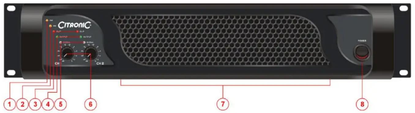
- PM Protect Mode indicator 5. SIGNAL indicators
- BM Bridge Mono mode indicator
- CLIP indicators 7. Cooling vent
-
OUTPUT indicators 8. POWER switch
-
CH1 and CH2 level controls
Rear Panel
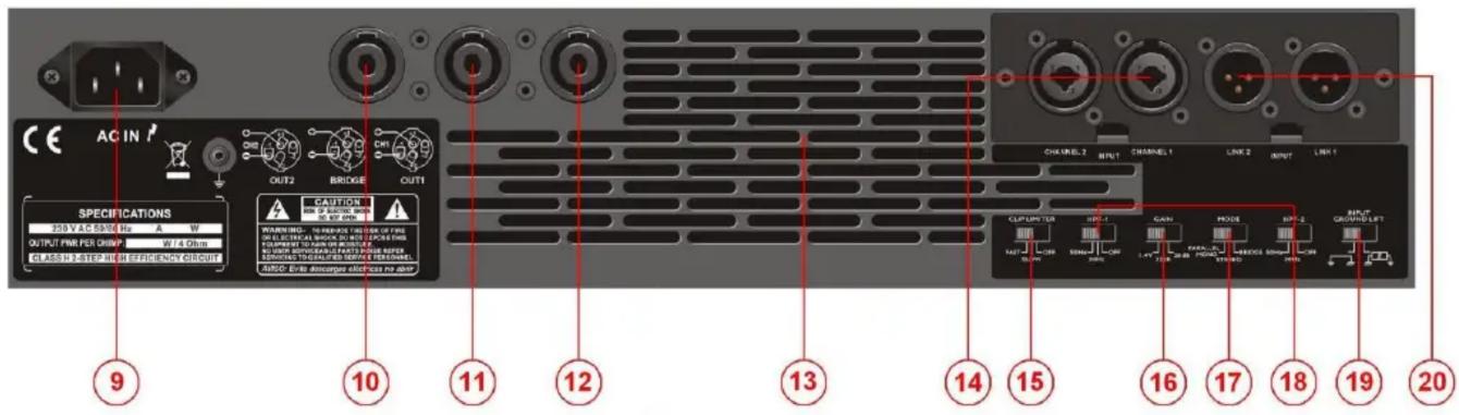
-
Mains inlet - IEC 15. CLIP LIMITER switch
-
CH2 output
- Bridge mono output
- CH1 output
- Cooling vent
-
Combo signal inputs (XLR or jack)
-
GAIN input level selector
- MODE switch (Parallel/Stereo/Bridge)
- CH1 and CH2 High Pass Filters (HPF)
- GROUND LIFT switch
- Signal line outputs (XLR)
Operation
Connect speaker cabinets to channel outputs using good quality leads and ensuring that the combined load on each channel is no lower than 4 (for speaker loads connected from one to another, 8 + 8 = 4 ).
Connect the left and right signal input from mixer or other line level source via the combo connectors on the rear panel using good quality 6.3mm jack or XLR leads.
If the signal is to be cascaded onto other amplifiers, connect these via the XLR line level outputs.
Connect the amplifier to the mains outlet, making sure that the IEC lead is in good condition and connected securely.
For extra protection of speakers and amplifier, the CLIP LIMITER may be switched in to help prevent overload. In some extreme cases, the operation of the clip limiter can be obtrusive. In these cases, disable the clip limiter and use a dedicated compressor/limiter to control the high dynamics.
If the amplifier is not driving sub cabinets or is driving cabinets which cannot produce very low frequencies, the High Pass Filters (HPF) may be switched in to avoid excessively low frequencies, which will not be able to be reproduced and thus dissipate as heat, reducing efficiency. Settings for 30Hz and 50Hz are available.
Select the GAIN level of the input signals (standard is 26dB – may also be used to curtail the input level)
Select the mode in which the amplifier is to be used...
- PARALLEL sums both left and right input signals together and feeds the mono signal to both amplifier outputs. This is useful when driving sub cabinets (which, in arrays, benefit from working together in mono) and when each channel is powering speakers in different areas (avoiding one area hearing only left output and the other only right)
• STEREO is the normal mode of operation where each input is delivered to each output independently - BRIDGE mode couples both amplifier sections together to deliver the full rated power to a single output. The minimum impedance is 8Ω in this mode. An LED (“BM”) shows when this mode is engaged
The GROUND LIFT switch disconnects signal ground (or “earth”) from mains ground. In certain cases, it may help to alleviate mains hum – otherwise, leave ground connected to mains ground.
With CH1 and CH2 level controls turned fully down, switch on the power to the amplifier. This product has a “soft-start” function which makes some checks before engaging power to the amplifiers, which may take a few seconds.
With mixer (or other signal source) levels turned down, gradually increase the amplifier's CH1 and CH2 level controls to the required level (normally full) and then gradually increase the signal level from the mixer until sound can be heard through the speakers and then up to the required level.
During use, the LED indicators will show if a signal is present, if half output is being produced and if the output is reaching clip level. If the red CLIP LEDs illuminate more than very briefly, reduce the volume until they hardly light up at all.
If the internal protection circuitry detects a fault in the speakers or amp, the amplifier will enter Protect Mode and a "PM" LED will illuminate on the front panel to show this. Switch the amplifier off and check the entire system (including leads) before powering up again. If still in Protect Mode, seek advice from qualified service personnel.
Before powering down, turn CH1 and CH2 level controls fully down to avoid loud noises when switching off.
| SPECIFICATIONS | ||
| PL3200 | PL3800 | |
| Power supply | 230Vac 50/60Hz (IEC, 15A max.) | |
| Output: RMS @ 4Ω | 2 x 1600W | 2 x 1900W |
| Output: RMS @ 8Ω | 2 x 915W | 2 x 1100W |
| Bridge power: RMS @ 8Ω | 3200W | 3800W |
| Input impedance | 20kΩ | |
| Output circuit architecture | Class H, 2-step | |
| Frequency response | 5Hz – 50kHz | |
| S/N ratio | >111dB | >112dB |
| THD | 0.05% | |
| Circuit protection | Short-circuit, DC, overload, soft-start | |
| Dimensions | 88 x 483 x 389mm | |
| Weight | 10.5kg | |
Troubleshooting
| No power light on front panel switch | Ensure IEC is connected to mains and mains lead is in good condition |
| Ensure mains outlet is switched on | |
| Power light is on but no other LEDs and not output | Check input signal and connection leads |
| Ensure CH1 and CH2 level controls are not turned fully down | |
| Power light and Signal LEDs are lit but no output | Check speaker cabinets are not blown and are in good working order |
| Check speaker leads are in good condition and connected properly | |
| “PM” (Protect Mode) LED is lit and there is no output | Switch off and disconnect from mains |
| Check speakers are in good working order and not shorted out (using a multi-tester) | |
| After checking all connected items, power up again | |
| If still in Protect Mode, switch off again and refer to qualified service personnel | |
| Output is very distorted and “CLIP” LEDs are lighting | Check speaker impedance is not below rated Ohms |
| Turn down Input level from audio source | |
| Switch GAIN at rear to a lower level | |
| Turn down CH1 and CH2 level controls | |
| Output is working but at very low level | Ensure input source is at line level |
| Increase input level from audio source | |
| Turn up CH1 and CH2 level controls | |
| Switch GAIN at rear to a higher level |
Note: for further troubleshooting, refer equipment to qualified service personnel for testing