
LE6016N-NH - Video recorder LG - Free user manual and instructions
Find the device manual for free LE6016N-NH LG in PDF.


| Product Type | Standalone DVR (Digital Video Recorder) |
| Model | LE6016N-NH |
| Operating System | Embedded Linux |
| Video Compression | H.264 Hardware Codec |
| Video Input | 16 channels, BNC composite |
| Video Output | 2 BNC (Main, Spot-out), 1 VGA (15-pin D-Sub) |
| Audio Input/Output | 4 line input / 1 line output |
| Recording Resolution | D1 (720x480), Half D1 (720x240), CIF (352x240) for NTSC; PAL equivalents |
| Recording Speed | Up to 480 fps (NTSC) / 400 fps (PAL) at CIF resolution |
| Storage | 2 internal SATA HDD (up to 1TB each); supports e-SATA external HDD |
| Backup Media | USB storage, network, optional external ODD |
| Network | Ethernet RJ-45 (10/100/1000 Base-T), DDNS, TCP/IP |
| Sensor Input / Alarm Output | 8 sensor inputs (NC/NO selectable) / 4 relay alarm outputs |
| Communication Port | RS-485 for PTZ control |
| Dimensions (W x D x H) | 430 mm x 330 mm x 57 mm |
| Weight (without HDD) | 2.65 kg |
| Power Supply | DC 12 V adapter, 60 W |
| Power Consumption | 20 W |
| Operating Temperature | 0 °C to 40 °C |
| Operating Humidity | 10% RH to 80% RH |
| Recording Modes | Continuous, alarm, motion detection, instant panic |
| Playback & Search | Time search (calendar), event search, bookmark, forward/backward at various speeds |
| PTZ Control | Supports Pan/Tilt/Zoom via RS-485; preset and tour functions |
| Remote Access | Web viewer (ActiveX) and iPhone/iPod mobile viewer |
| Cleaning Instructions | Use only a dry cloth; no water, chemicals, or detergents |
| Safety & Servicing | No user-serviceable parts inside; refer all servicing to qualified personnel |
| Spare Parts | Replaceable hard disk (SATA); battery replacement with same type recommended by manufacturer |
Frequently Asked Questions - LE6016N-NH LG
User questions about LE6016N-NH LG
0 question about this device. Answer the ones you know or ask your own.
Ask a new question about this device
Download the instructions for your Video recorder in PDF format for free! Find your manual LE6016N-NH - LG and take your electronic device back in hand. On this page are published all the documents necessary for the use of your device. LE6016N-NH by LG.
USER MANUAL LE6016N-NH LG
Please read this manual carefully before operating your set and retain it for future reference.
MODEL
LE6016N
LE6016D
1 Safety Information

CAUTION
RISK OF ELECTRIC SHOCK DO NOT OPEN

CAUTION: TO REDUCE THE RISK OF ELECTRIC SHOCK DO NOT REMOVE COVER (OR BACK) NO USER-SERVICEABLE PARTS INSIDE REFER SERVICING TO QUALIFIED SERVICE PERSONNEL.

This lightning flash with arrowhead symbol within an equilateral triangle is intended to alert the user to the presence of uninsulated dangerous voltage within the product's enclosure that may be of sufficient magnitude to constitute a risk of electric shock to persons.

The exclamation point within an equilateral triangle is intended to alert the user to the presence of important operating and maintenance (servicing) instructions in the literature accompanying the product.
FCC WARNING: This equipment may generate or use radio frequency energy. Changes or modifications to this equipment may cause harmful interference unless the modifications are expressly approved in the instruction manual. The user could lose the authority to operate this equipment if an unauthorized change or modification is made.
REGULATORY INFORMATION: FCC Part 15
This equipment has been tested and found to comply with the limits for a Class A digital device, pursuant to Part 15 of the FCC Rules. These limits are designed to provide reasonable protection
against harmful interference when the equipment is operated in a commercial environment.
This equipment generates, uses, and can radiate radio frequency energy and, if not installed and used in accordance with the instruction manual, may cause harmful interference to radio communications. Operation of this equipment in a residential area is likely to cause harmful interference in which case the user will be required to correct the interference at his own expense.
- A suitable conduit entries, knock-outs or glands shall be provided in the cable entries of this product in the end user.
- Caution: Danger of explosion if battery is incorrectly replaced. Replace only with the same or equivalent type recommended by the manufacturer. Dispose of used batteries according to the manufacturer's instructions.
- Holes in metal, through which insulated wires pass, shall have smooth well rounded surfaces or shall be provided with brushings.
This Class A digital apparatus complies with Canadian ICES-003.
Warning: Do not install this equipment in a confined space such as a bookcase or similar unit.
Warning: Wiring methods shall be in accordance with the National Electric Code, ANSI/NFPA 70.
Warning: This is a class A product. In a domestic environment this product may cause radio interference in which case the user may be required to take adequate measures.
Warning: To reduce a risk of fire or electric shock, do not expose this product to rain or moisture.
Caution: This installation should be made by a qualified service person and should conform to all local codes.
Caution: To avoid electrical shock, do not open the cabinet. Refer servicing to qualified personnel only.
Caution: The apparatus should not be exposed to water (dripping or splashing) and no objects filled with liquids, such as vases, should be placed on the apparatus.
Caution:
This product employs a Laser System. To ensure proper use of this product, please read this owner's manual carefully and retain it for future reference. Should the unit require maintenance, contact an authorized service center. Performing controls, adjustments, or carrying out procedures other than those specified herein may result in hazardous radiation exposure. To prevent direct exposure to laser beam, do not try to open the enclosure. Visible laser radiation when open. DO NOT STARE INTO BEAM.
To disconnect power from mains, pull out the mains cord plug. When installing the product, ensure that the plug is easily accessible.
CE
LG Electronics hereby declares that this/these product(s) is/are in compliance with the essential requirements and other relevant provisions of Directive 2004/108/EC, 2006/95/EC, and 2009/125/EC.
European representative:
LG Electronics Service Europe B.V. Veluwezoom 15, 1327 AE Almere, The Netherlands (Tel: +31-(0)36-547-8888)
Disposal of your old appliance

- When this crossed-out wheeled bin symbol is attached to a product, it means the product is covered by the European Directive 2002/96/EC.
- All electrical and electronic products should be disposed of separately from the municipal waste stream via designated collection facilities appointed by the government or the local authorities.
- The correct disposal of your old appliance will help prevent potential negative consequences for the environment and human health.
- For more detailed information about disposal of your old appliance, please contact your city office, waste disposal service, or the shop where you purchased the product.
EEE Compliance with Directive (for Turkey only).
IMPORTANT SAFETY INSTRUCTIONS
- Read these instructions.
- Keep these instructions.
- Heed all warnings.
- Follow all instructions.
- Do not use this apparatus near water.
- Clean only with dry cloth.
- Do not block any ventilation openings. Install in accordance with the manufacturer's instructions.
- Do not install near any heat sources such as radiators, heat registers, stoves, or other apparatus (including amplifiers) that produce heat.
- Do not defeat the safety purpose of the polarized or grounding-type plug. A polarized plug has two blades with one wider than the other. A grounding type plug has two blades and a third grounding prong. The wide blade or the third prong are provided for your safety. If the provided plug does not fit into your outlet, consult an electrician for replacement of the obsolete outlet.
- Protect the power cord from being walked on or pinched particularly at plugs, convenience receptacles, and the point where they exit from the apparatus.
- Only use attachments/accessories specified by the manufacturer.
- Use only with the cart, stand, tripod, bracket, or table specified by the manufacturer, or sold with the apparatus. When a cart is used, use caution when moving the cart/apparatus combination to avoid injury from tip-over.

- Unplug this apparatus during lightning storms or when unused for long periods of time.
- Refer all servicing to qualified service personnel. Servicing is required when the apparatus has been damaged in any way, such as power-supply cord or plug is damaged, liquid has been spilled or objects have fallen into the apparatus, the apparatus has been exposed to rain or moisture, does not operate normally, or has been dropped.
Please follow the directions to safely use the product.
The purpose of the following safety precautions is to prevent any unexpected risk or damage by using the product accurately as intended.
Warning
- Turn off the power of the product before installing the product. Do not plug many plugs into one outlet.
- It can cause an electric shock or a fire.
- Do not put any containers with liquid such as water, coffee, beverage, etc. on top of the product.
- It can cause a fire, an electric shock, or a product problem.
- Do not place heavy objects on top of the cable or bend it excessively.
- It can cause a fire.
- When wiping the surface of the product, do not use water, chemicals, or detergents; always use a dry towel.
- It can cause an electric shock, problems, or scratches to the surface of the product.
- Do not install the product in areas with high humidity, dust, or smoke.
- It can cause an electric shock or a fire.
- When unplugging the power, hold the plug and unplug slowly. Do not hold the plug with wet hands or plug it into a loose power outlet.
- It can cause an electric shock or a fire.
- Do not disassemble or reconfigure the product. Because high levels of current flow through the device, it is dangerous to do so.
- It can cause a fire, an electric shock, or an injury.
- Always check for dangerous elements where the product is installed. If dangerous elements (moisture, damaged cable, unstable installation, etc.) are identified, please contact your nearest service center.
- It can cause an electric shock or a fire.
- Because the cable connected to this device can be damaged, keep at least 15 cm of clearance between where the product is installed and where the power outlet is.
- It can cause a fire, an electric shock, or an injury.
• Install the product in a cool location not exposed to direct sunlight. Do not install the product where traffic is high or near heating devices.
- It can cause a fire.
• Install the product on a flat surface where it is well ventilated and not too high.
- It can cause a problem or an injury.
- The power outlet must be grounded and the voltage range must be within 10% of the rated voltage. Do not share the power outlet with a hair dryer, iron, refrigerator, or heating device, etc.
- It can cause an explosion.
- When replacing the battery, always replace with the same type of battery as the one provided. When disposing of the battery, follow the manufacturer's directions.
- It can cause an explosion.
- For old hard drives, you may not be able to recover the data stored on the drive. When you use a damaged hard drive, you will see a sign on the screen saying "Error or defective". For the old hard drive, contact your nearest service center or the original retailer to replace the hard drive.
- LG Electronics is not responsible for data loss from misuse by the user.
Any changes or modifications in construction of this device which are not expressly approved by the party responsible for compliance could void the user's authority to operate the equipment.
Caution
Please read the following precautions carefully before installing the product and follow the directions for installation.
- Do not install the product where the level of humidity, dust, or smoke is high.
- Do not install the product where it is exposed to direct sunlight or close to a heating device.
- Do not install the product where there is danger of electric shock or near magnetic objects.
- Do not place objects with high conductivity on top of the ventilation outlet of the product.
- Make sure the power is turned off before installing the product.
- Secure sufficient space to connect the product when installing it.
- Do not install the product on an uneven surface, in a poorly ventilated area, or where vibration is severe.
- Installing the product near electronic appliances such as radios or TVs can cause problems.
- Do not disassemble the product unless done by a technician certified by LG Electronics.
- Do not place heavy objects on top of the product.
- Be careful not to let foreign particles get inside the product.
- This can cause problems with the product.
• Install the product in a well-ventilated area.
- Keep the product at least 15 cm away from the wall power outlet because the cable can be damaged.
- Do not install the product near a product or broadcast receiver with strong electric or magnetic waves.
- Do not place heavy objects on top of the product.
- This can cause problems with the product.
• Install the product at a flat and stable location.
- The product may not operate normally.
- Place the product at a location with appropriate temperature and humidity levels.
- Do not install the product where the temperature is too high (40 °C or above) or too low (0 °C or below).
- Since vibration and impact can damage the product, do not throw any objects at the location where the product is installed.
- Do not install the product where it is exposed to direct sunlight or close to a heating device.
- Firmly fixate the product in a well-ventilated location.
- Depending on the surrounding environment, problems may occur. It is recommended to use an Automatic Voltage Regulator. It is recommended to wrap wires around the Ferrite core.
- The power outlet must be grounded.
- If you hear any noise or smell any odor from the product, turn the product off and contact your nearest service center.
- It can cause a fire or an electric shock.
• Periodically have the product checked by the service center to ensure safe use of the product.
- When replacing the battery, always replace with the same type of battery as the one provided. When disposing of the battery, follow the manufacturer's instructions.
- LG Electronics is not responsible for problems resulting from misuse by the user.
- Do not move or flip the product over while using the product.
Contents
1
Safety Information
4 IMPORTANT SAFETY INSTRUCTIONS
5 Please follow the directions to use the product safely
2
Before use
10 2-1. Product characteristics
11 2-2. Components
11 2-3. Front side
11 LE6016D model
12 LE6016N model
13 2-4. Rear side
14 2-5. Remote Controller
14 How to set the id of remote controller
15 2-6. Connection and initial setting
16 RS-485 connection
16 Control port (Output) connection
17 Sensor (Input) connection
17 About internal hard disk
18 Hard disk installation or replacement
3
Functional description
22 3-1. Operation
22 Start Up
23 Shutdown
24 3-2. Monitor Screen
28 3-3. System Setting
28 System
33 Camera
38 Event
42 Network
46 Information
49 3-4. PTZ Control
51 3-5. Search (Playback) & Backup
51 Time search 52 Event Search 54 Backup
4
Web viewer
58 4-1. Installation 58 Web viewer installation 60 4-2. Functional description 60 Web viewer monitoring window 61 Web viewer search window 62 Search dialog box 63 Saving as AVI file dialog box
5
Apple iPhone/iPod
64 5-1. Functional description 64 Real-time monitoring
6
Reference
66 6-1. Check before requesting for
service
70 6-2. Recommended device to use 70 List of recommended USB memory 71 Recommended list of CD/DVD media 72 List of supported PTZ camera 73 6-3. Initial setting list for factory default 80 6-4. Product specification
2
Before use
2-1. Product characteristics
- Adopted the stable Embedded Linux
- Stable file system recovery even after power supply is disconnected from a power outage. • Realized small file size and high video quality by applying the H.264. • Supports terra byte hard disk (up to 1TB) • Supports E-SATA port to use additional external hard disk. • Real time recording
-Maximum of 480 IPS@352 X 240 at NTSC
-Maximum of 400 IPS@352 X 288 at PAL
• Supports various recording resolutions and qualities.
-D1(720x480), Half D1(720x240), CIF(352x240) at NTSC
-D1(720x576), Half D1(720x288), CIF(352x288) at PAL
- 5 stage recording qualities (Very high, high, normal, low, very low).
- Easy operation through various user interface and user friendly GUI system.
• Realized powerful multi-function.
- Real time video display or recording, network transmission and back up can be performed simultaneously
- Easy search functions.
-Date/Time search (Calendar search), event search
- Recording before event. (Can be 2~4 seconds).
- Recording after event. (Can be only up 10 seconds).
- The operating condition pre-check function according to the change in motion detection and movement detection
- Can set recording quality and number of recording frames per seconds.
- Powerful recording schedule management.
- Complete synchronization of video/audio.
- Easy software upgrading through USB storage device or network. • Maximum of 5 clients can be connected to 1 DVR at the same time.
- Band width setting is automatically set depending on the network speed connected to this device.
- Remote alarm notification via e-Mail.
- PTZ (Pan/Tilt/Zoom) operation.
- Remote control operation • Key board control operation (optional) • Supporting Daylight saving • Simultaneous output to VGA and BNC
2-2. Components
Reference: The type of components can be applied differently by the option.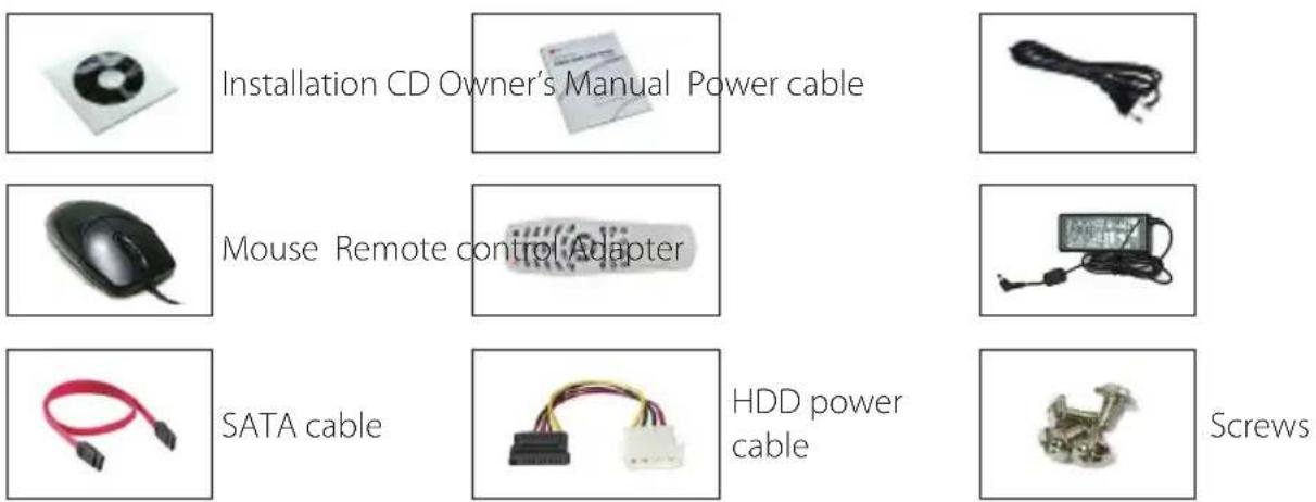
2-3. Front side
LE6016D model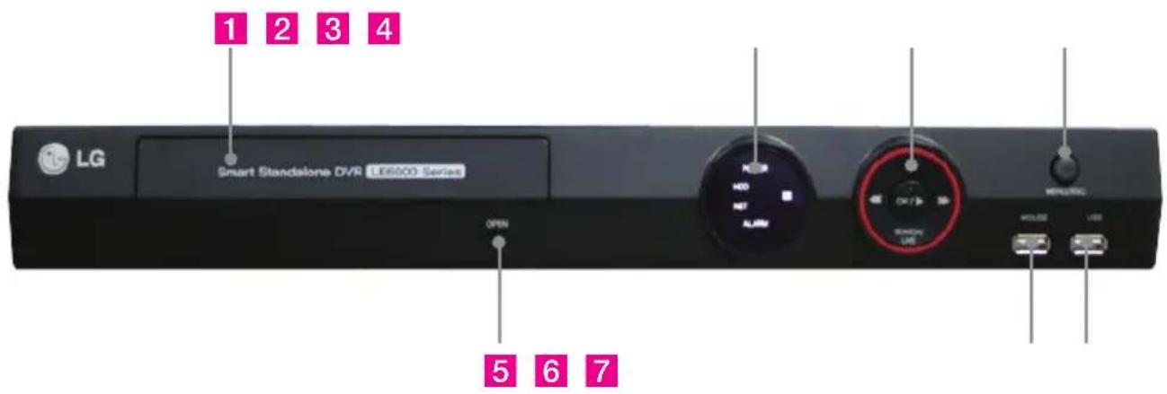
LE6016N model
There is no built-in DVD recorder at LE6016N model.
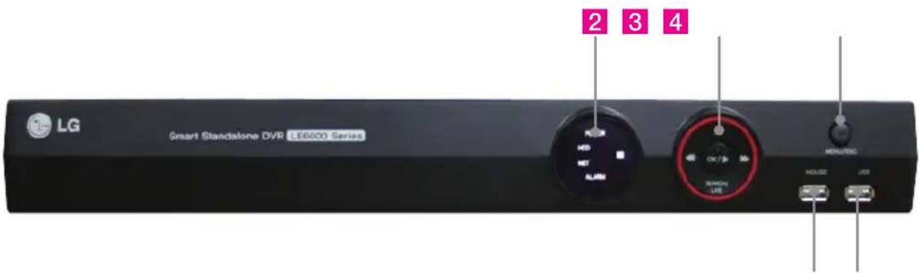
6 7
1 DVD Recorder: This is used for DVD backup. 2 LED
- Hard disk LED: This is turned on HDD is accessed. • Power LED: This is turned on when the power is turned on. • Network LED: This is turned on when network is connected.
- Alarm LED: This is turned on when alarm event occurs.
3 Navigation buttons
- At power off status, it is turned on by pressing "OK" button in some seconds.
- At power on status, instant panic recording is executed by pressing "OK" button in some seconds.
- "SEARCH/LIVE" button is used as navigation key, when menu is shown, on the Chapter 1 Before use other hand, it is used for switching key between SEARCH and LIVE screen when menu not be shown.
4 MENU/ESC: Used to open or close the menu. 5 OPEN: Used to open or close the DVD recorder door. 6 MOUSE: Used to connect a mouse. 7 USB: Used to connect a USB external device.

CAUTION
The mouse should be connected to the front side mouse port.
2-4. Rear side
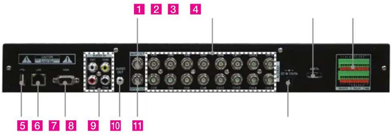
1 Main output port: Used to connect a BNC type monitor. (It outputs the same video as the MAIN output.) 2 Camera video input: Used to connect cameras. 3 External HDD port: Used to connect an E-SATA HDD. 4 Sensor/Alarm/RS-485 ports: Used to connect sensor, alarm, and RS-485 serial communication ports. 5 USB port: Used to connect a USB external device. 6 Ethernet port: Used to connect an RJ-45 Ethernet connector (LAN port). 7 VGA port: Used to connect a VGA monitor. 8 Audio input port: Used to connect the audio output port of an external device. 9 Audio output port: Used to connect the audio input port of an external device. 10 SPOT output port: Used to connect a BNC type monitor. 11 Power connector: Used to connect the power adapter.
2-5. Remote Controller
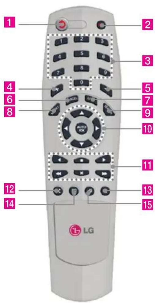
| No. | Function Description | |
| 1 | Power This is used to turn on/off the power. | |
| 2 | Emergency recording | This is used to start/stop emergency recording. |
| 3 | Number keys This is used to input channel or values. | |
| 4 | Plus(+) This is used to increase setting values. | |
| 5 | Minus(-) This is used to decrease setting values. | |
| 6 | CANCEL This is used to cancel a job. | |
| 7 | LIVE This is used to display real time screen. | |
| 8 | MENU This is used to display menu. | |
| 9 | SEARCH This is used to display screen search. | |
| 10 | ▼◀▶ ,OK | This is used to navigate each menu item. |
| 11 | Play buttons | These are used to control playback (Backward or forward search, play and pause)※ [IMAGE] and [buttons have no function. |
| 12 | PTZ Menu This is used to open PTZ Menu. | |
| 13 | Export backup | This is used to run backup.※ It can be run in search mode. |
| 14 | Split screen This is used for split screen display. | |
| 15 | Auto switching | This is used to display channel one by one.※ It works as event search at search mode. |
Note: The shape of the remote controller may vary by model.
How to set the ID of the remote controller
- Press the CANCEL button for about 3 seconds, then the light of the power button turns on.
- Enter two-digit numbers for the remote controller ID using the number keys.
※ You must input '0' first when entering a one-digit number. Ex) To use '2' as the ID, input '02'.
- Every time you press a number key, the light of the power button will blink.
- When the blinking stops, the ID is saved.
2-6. Connection and initial setting
Caution
- The camera or other external devices can be connected to this device in numerous ways. Refer to the user manual of the camera or other external device for additional information on connection methods.
- When installing the camera, check whether the power of the camera is turned off. • After installing the monitor, turn on the power of the DVR.
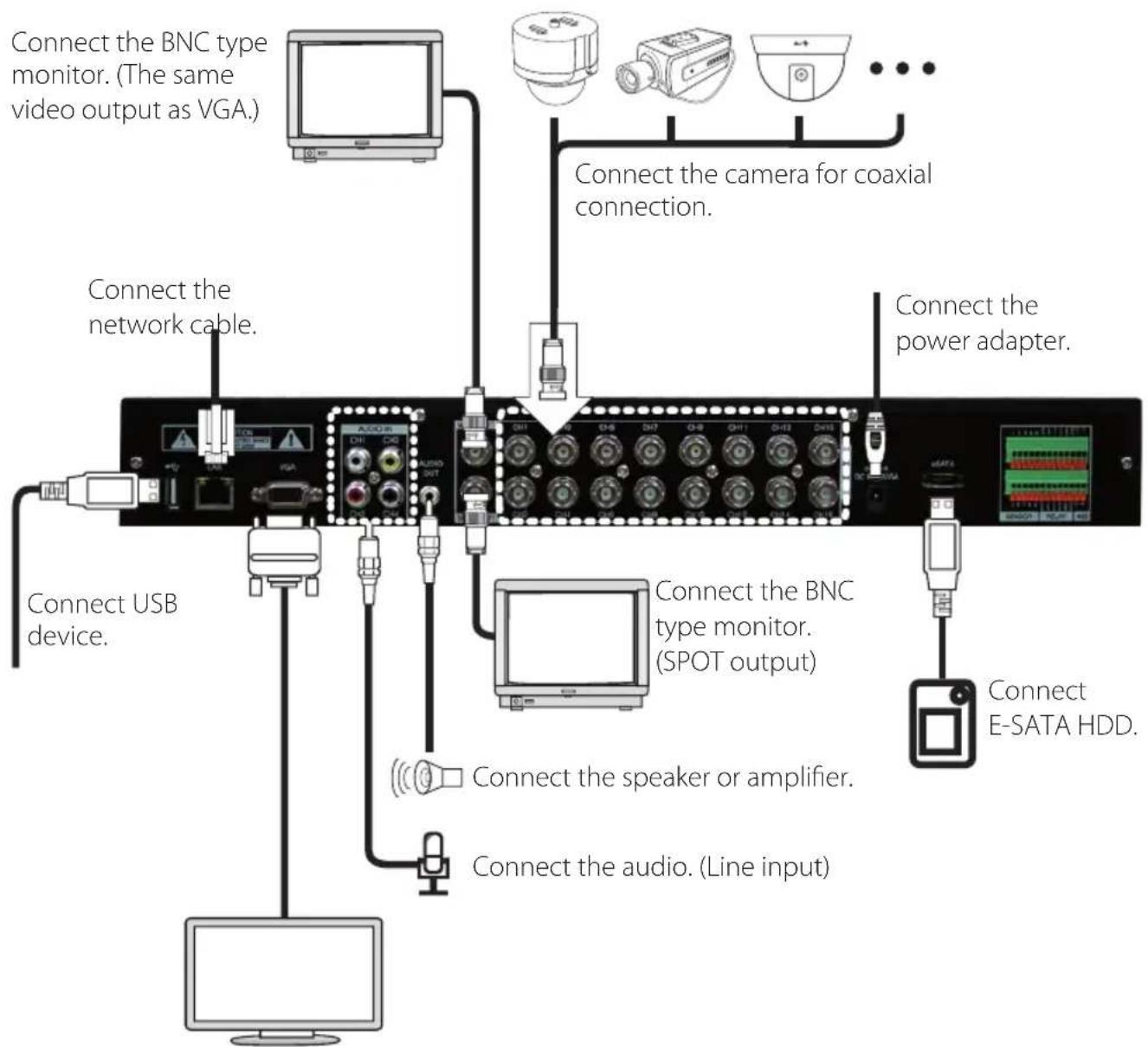
Connect VGA monitor.
RS-485 connection
① This device has 1 data port (RS-485). ② Use this port to connect the PTZ camera or the keypad. (Optional) ③ PTZ camera / keyboard connection
i. Connect the PTZ serial communication cable to the RS-485 port. ii. When connecting the cable, make sure that the TX- of the device is connected to the RX-(TX-) of the camera(keyboard), and TX+ of the device is connected to the RX+(TX+) of the PTZ camera(keyboard).
iii. Recommended initial data setting is 9 600 baud rate, 8 data bits, 1 stop bit and no parity.
iv. When connecting the PTZ camera or keyboard, always change the setting of the DVR setting menu according to the RS-485 setting of the camera, keyboard and this device.
v. Set the same baud rate when you are to use PTZ camera and keyboard at the same time
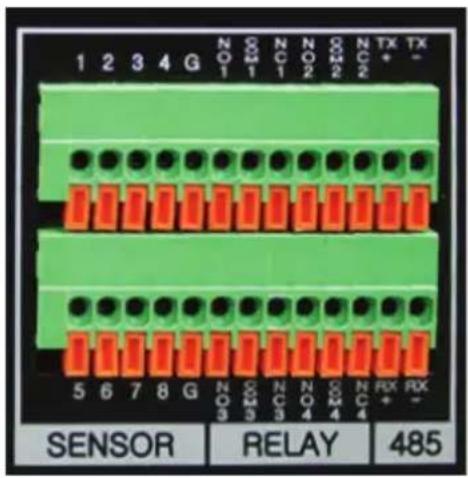
Control port (Output) connection
① For interface and auto control with the external sensor, the interfacing control output port (Set value from "Setup → Event → Sensor/Motion/Video loss" menu) and the "RELAY" port are connected. ② If the control device (Alarm light, amplified siren, external relay etc.) is "NC (Normal Close)" type, connect to the control output NC (Normal Close) port. ③ If the control device (Alarm light, amplified siren, external relay etc.) is "NO (Normal Open)" type, connect to the control output NO (Normal Open) port.
Sensor (Input) connection
Connect one of the signal cables (2 cables) of various sensors (IR sensor, heat ray detector, magnetic etc.) to the COM port and connect the remaining signal cable to the sensor number you want. (Sensor "NC, NO" type can be set from "Setup → Event → Sensor" menu.)
| 1 Sensor input 1 |
| 2 Sensor input 2 |
| 3 Sensor input 3 |
| 4 Sensor input 4 |
| G Ground |
| 5 Sensor input 5 |
| 6 Sensor input 6 |
| 7 Sensor input 7 |
| 8 Sensor input 8 |
| G Ground |

NOTE
NC and NO cannot be selected simultaneously.
About internal hard disk
The hard disk installed inside the device is a precision device which can be damaged even with the small impact. To prevent the hard disk from being damaged, manage the device as follows.
To prevent the data loss, it is recommended to back up any important data into an external storage device. When installing or uninstalling the hard disk, you must always turn off the power of the product.
- If the power is turned on, do not move the device.
- Do not install this device where it is too hot and humid and where the temperature change is sudden. It can cause a problem to the device.
- DO NOT pull out the plug or intercept the power supply while this device's power is on.
- When there is a power outage while the power is turned on, some data can be lost.
- Do not drop the hard drive or put any metallic object, such as coins, inside the device.
- In case of a power outage while recording, avoid adding, replacing or moving the HDD. The recorded data can be lost. In this case, turn on the power with the original hard disk that was used while the power outage occurred. And then add, replace or move the HDD.
- Because the hard disk is a high precision device, the parts inside the disk can be damaged at the slightest impact. Please read the following precautions in detail and follow the directions.
- Do not directly put the hard disk on the desk or table. Because the parts inside the hard disk can be damaged at the slightest impact, put a thick cushion below the hard disk.
- If you use the motored driver, the parts inside the hard disk can be damaged from the vibration.
- When replacing the hard disk, be careful not to cause any impact to the other parts.
- Be careful not to cause an impact from the tools and hard disk used for the installation.
- Protect the hard disk from static electricity.

CAUTION
This device has components that can cause electric shock, accidents, or product malfunction. Additionally, the hard disk may not be recognized or operate properly if installed or configured incorrectly. Therefore, consult an experienced technician when installing the hard disk.
Hard disk installation or replacement
Hard disk installation
After turning on the device's power, unplug it from the outlet.
- Loosen the screws on the left, right, and rear sides of the product.
- Remove the cover of the main unit.
- Remove the screws on the bracket holding the hard disk, then separate the bracket from the hard disk.
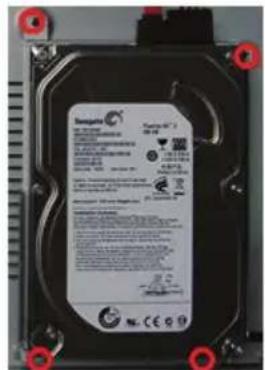
- Install the hard disk onto the bracket and tighten the 4 screws.
Connecting bracket to hard disk
Set the SATA cable connection port to face downward when installing the hard disk onto the bracket.
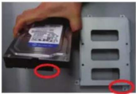
Connect the bracket to the hard disk by tightening the 4 screws.
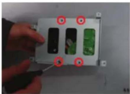
- After installing the bracket on the main unit, tighten the screws.
- Connect the power cable of the hard disk.
- Connect the SATA cable to the hard disk.
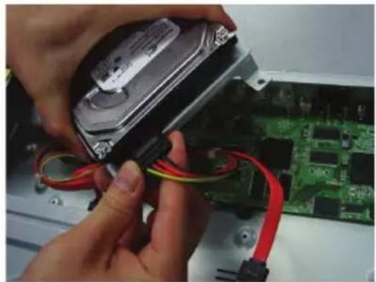
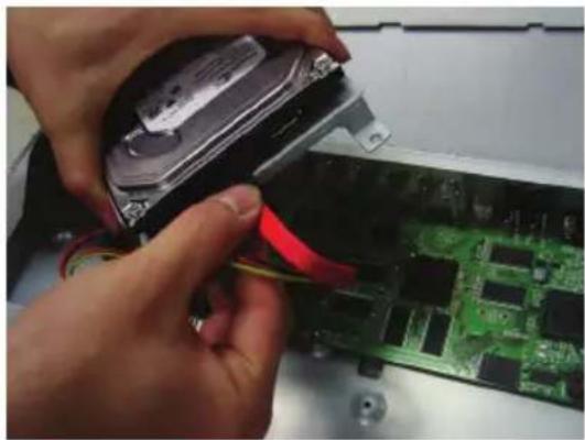
- Connect the SATA cable to the SATA port of the main board.
- Close the cover of the main unit.
- Tighten the screws.
- After installing the hard disk, you must format the hard disk from the setting menu.
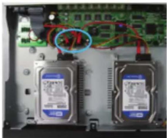
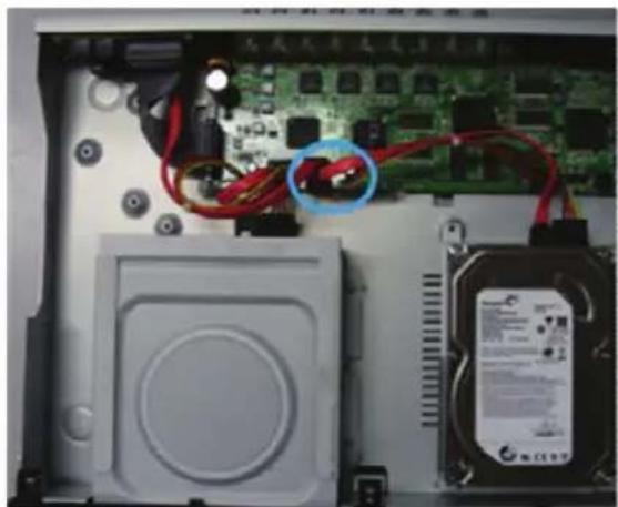
- The first SATA cable port on the main board must be connected at all times. If a hard disk is not connected, this device may not operate normally.
Hard disk replacement
First turn off the power of the device and then unplug the power.
- Loosen the screw on the left, right and rear side of the product.
- Separate the cover of the main unit.
- After removing all of power/SATA cable connected to hard disk, please separate hard disk bracket from the body.
- Loosen the screws on the left and right side of the bracket holding the hard disk.
- Separate the hard disk from the bracket holding the hard disk.
- In the reverse order of removing the hard disk, assemble the new hard disk.
- After replacing the hard disk, turn on the power of the device.
- Reference
- Each SATA cable must be connected to the connecting port precisely.
- Do not vertically put the hard disk in upright position or put other objects on top of the hard disk.
- When connecting/disconnecting the hard disk, do not use a motored tool.
-Refer to the following when adding/replacing the hard disk.
Connecting E-SATA HDD
- Turn off the power of DVR then connect E-SATA HDD to E-SATA port. And turn on the power of E-SATA HDD first then turn on the power of DVR.
- E-SATA HDD is used only for recording, it cannot be used for any other purpose like backup, for example.
Recommended list of hard disk
The hard disks listed below have been proven compatible through testing. Please refer to this list when adding or replacing the hard disk.
| CapacityLE6016 | ||
| 250 GB | ST3250310CS | Seagate |
| ST3250312CS | ||
| 500 GB ST3500312CS | ||
| 1 TB ST3100322CS | ||

CAUTION
When you select the hard drive to use for resetting, the previously saved video data will be deleted. Therefore, you must be careful.
Database recovery of the HDD
- The system checks the database condition during system booting. If there is a problem, the system will display a confirmation window to recover the database.
- Recovery time of the database is proportional to the amount of data.
- Recovery time takes more than 16 times longer if the database recovery includes event data.
- Basically, the recorded data is not damaged because backup data is always created.
Arrangement of the database on the HDD
- The system will display a confirmation window to arrange the database at reboot time every 6 months when the device is used normally. If you do not arrange the database, the system will perform the database arrangement every 12 months at booting.
Check the HDD problem
- If you install the hard disk for the first time, or perform initialization, or shut down the equipment abnormally more than three times consecutively, the system checks the integrity of the hard disk when booting.
- The system will randomly check for bad sectors on the hard disk.
3
Functional description
3-1. Operation
Start Up
- Turn on this device, then it boots with power indicator light turned on.
- After booting it will be displayed as the LOGOUT id.
- Pressing the lock button, then the login window would be displayed. Select user and press "OK" button to continue.
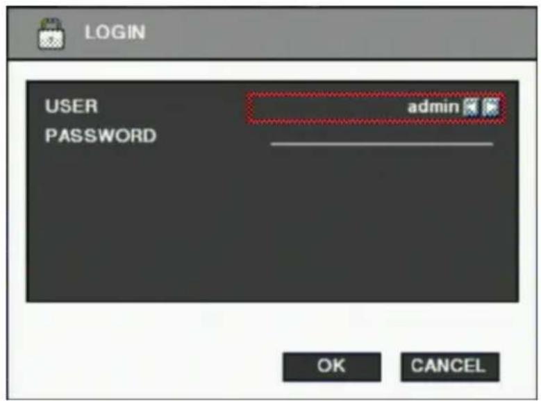
[USER]
You may select user to login and authority is restricted by kind of user. The access rights can be set for each user.
1) admin for system administrator (Access rights to Live, Search and Setup) 2) user1/user2/user3 for general user (Access rights can be set by administrator)
[PASSWORD]
The default user and password are set to 'admin' and '000000' as shown above. Click password input area, you will see the screen keypad as right.
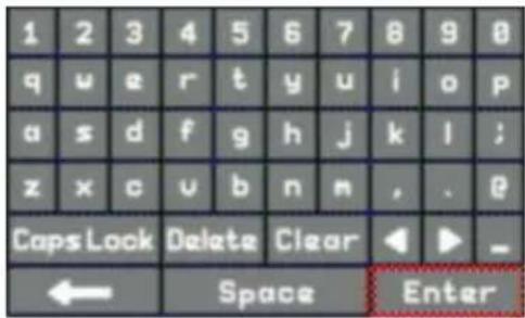
- Input password by using virtual keypad on screen.
- Click "OK" button to execute DVR system and you will see live screen.
Shutdown
- While the status is logged in, press button, then logout window will be displayed as below.
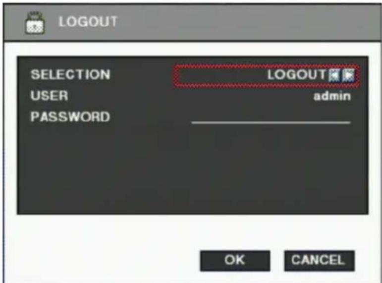
SELECTION: Select the Log Out or EXIT. ■ USER: Displays the current user who has logged in (admin/user1/user2/user3). ■ PASSWORD: Input password.
- Click the "OK" button to "Log Out" or "DVR Shutdown".
3-2. Monitor Screen
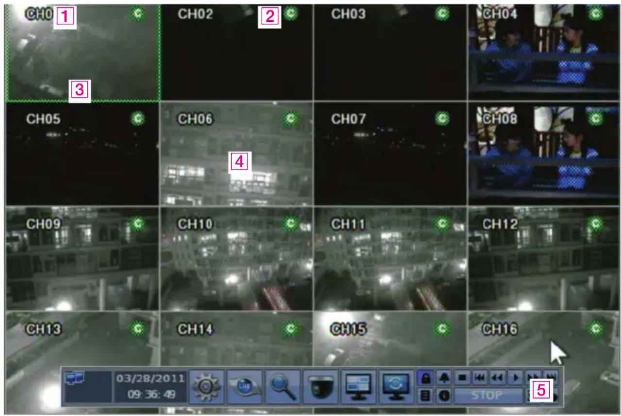
1 [Camera name]
• Shows the camera name. - If you want to modify the camera name, you can do so by selecting [Setup] → [Camera] → [Channel].
2 [Status icon] (OSD)
- The status icon shows the current status of the camera/recording.
- (OSD Feature)
| Item Icon Description Item Icon Description | |||||
| Camera |  | Audio Icon | Recording by Motion Recording |  | Immediate Recording |
 | Motion Icon Recording |  | |||
 | PTZ Icon Non Recording |  | |||
| Recording |  | Continuous Recording |  | Recording by Sensor | |
3 [Channel selection]
- The selected channel shows a green rectangle on the edge of the screen.
4 [Live view]
• It shows the current live view in real time.
5 [System control toolbar]
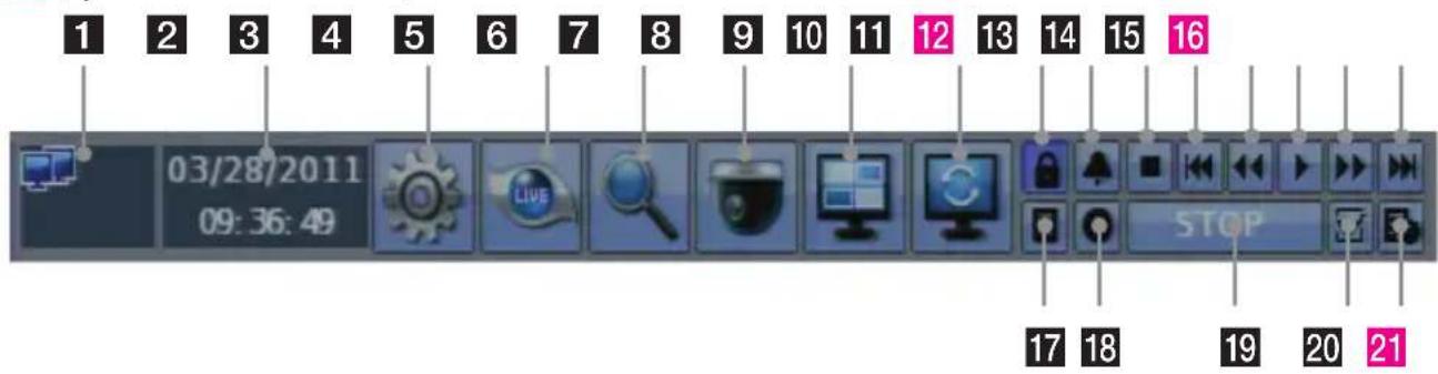
1 [Network status display]
- It shows the current connection status of the network.
(Black: It shows disconnected status.)

(Blue: It shows connected status.)
- If you want to modify network settings, you can do so by selecting [Setup] → [Network] → [TCP/IP]
2 [Current Date/Time]
- Current date and time is displayed.
- If you want to modify date and time, you can do so by selecting [Setup] → [System] → [Date]
3 [Setup]
- Set the system environment and function. • Refer to Chapter "3-3. System Setting".
4 [Live screen]
- This is the button to switch over to the live display window to view the realtime video screen.
5 [Search]
• This is the button to switch over to the search window to view the recorded screen. • Refer to Chapter "3-5. Search (Playback) & Backup"
6 [PTZ control]
• This is the button to control the PTZ camera • Refer to Chapter "3-4. PTZ Control".
7 [Divided screen selection]
• 1/4/9/13/16 divided screen can be displayed in live view.
8 [Auto sequential]
- Click button and each channel will be switched automatically.
• This function does not work at 16 divided screen.
- You can set the switching interval at [Setup] → [System] → [Overview] → [Auto-switching].
9 [Logout]
- Use Lock menu to change user or lock system operation.
10 [Relay out off(Alarm off)]
- When alarm (relay out) is on by event, you can stop the alarm with it.
- Press button to stop alarm (relay out).
- If next event occurs after alarm (relay out), the alarm will start again.
11 [Stop]
- Click this button to stop playback recorded data.
12 [Reverse frame by frame playback]
- Click this button to search the data with reverse frame by frame playback.
13 [Fast backward playback]
- Click this button to play back in fast reverse. The speed of fast reverse playback can be set to one of the following: X2, X4, X8, and X16.
14 [Forward playback]
- Click this button to play back forward at normal speed.
• The live screen can be switched to playback instantly by clicking this button.
15 [Fast forward playback]
- Click this button to play back in fast forward. The speed of fast forward playback can be set to one of the following: X2, X4, X8, and X16.
16 [Forward frame-by-frame playback]
- Click this button to search data with forward frame-by-frame playback.
17 [System Log]
• This shows the system log in the DVR.
- Click the button to show the system log list.
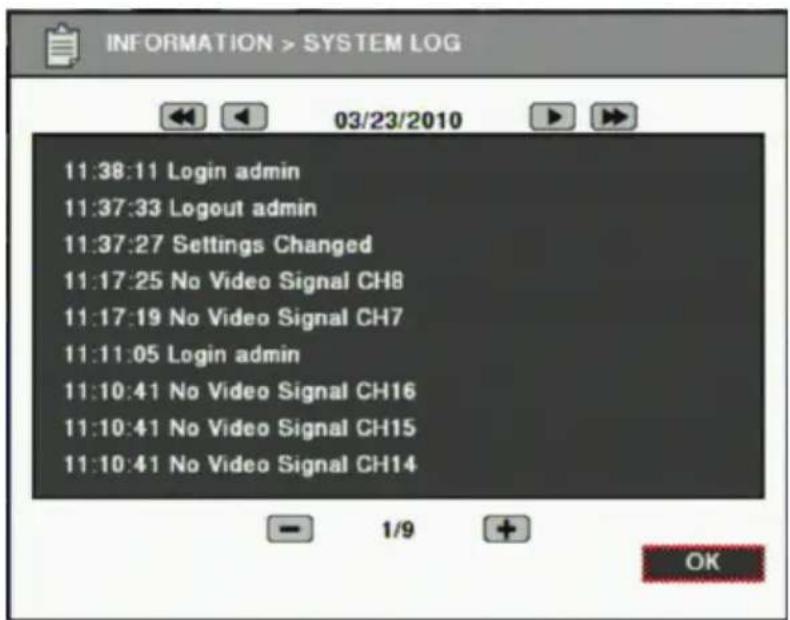
- You can see the log of the previous or next date by using the ◀/▶ buttons.
- You can see the previous or next log list by using the (-) / (+) buttons.
- Click the "OK" button to close the window.
- Clicking the button in search mode will display the Event search dialog box. Refer to "Event search".
18 [Information]
• Displays system information.
19 [Playback status]
• Displays playback status.
20 [Bookmark]
- You can add a playback position (date/time) to access it immediately later.
21 [Backup]
- Click this button to run backup of recorded data. • Refer to Chapter "3-5 Search (Playback) & Backup".

NOTE
- You can show or hide the system control bar by double-clicking the right mouse button.
- If the HDD has some bad sectors, the HDD information will be displayed on the top right of the screen.
3-3. System Setting
System settings can be configured via the setup menu. Working conditions can be specified using the front buttons, mouse, or remote controller.
Only the admin user can set up system configuration via the menu.
System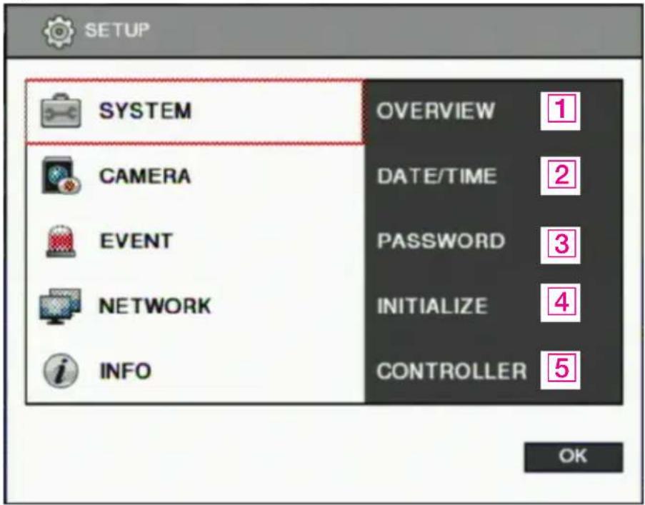
1 [Overview]
- You can specify the system configuration by this menu.
- Use ◀ / ▶ button to change configuration.
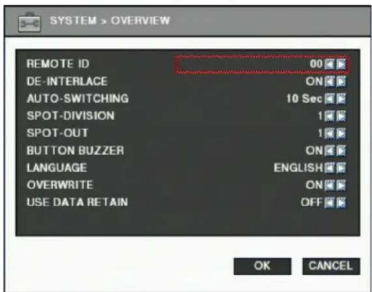
■ REMOTE ID: ID can be selected from 00 to 99. DE-INTERLACE: Enable or disable de-interlace feature for playback screen. De-interlace feature is only available for 'D1' resolution. ■ AUTO SWITCHING : Set dwell time when auto switching function is working. (1 Sec ~ 30 Sec) ■ SPOT-DIVISION: Set the division mode for SPOT OUT screen. - SPOT-OUT: Select spot channel. (channel 1~16, AUTO). If you select "AUTO", Spot will be changed sequentially.
※ When spot channel is changed automatically, dwell time that specified by Spot from AUTO SWITCHING is applied.
■ BUTTON BUZZER : Select button buzzer on / off.
LANGUAGE: Select language.
OVERWRITE: If you select "ON", when recording space of HDD is exhausted, it overwrites on the oldest recorded data to continue recording.
■ USE DATA RETAIN : data saving period can be set from 1 day to 60 days.
2 [Date/Time]
- Specify date and time of system.
- You can specify setting by using ◀ / ▶ button
- Select date and time, then you will see virtual keypad as below.
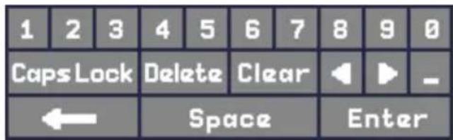
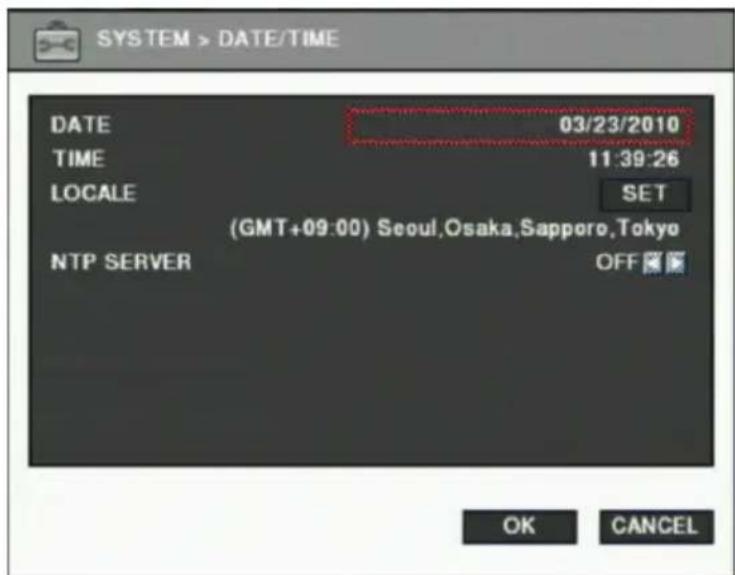
■ DATE : Specify current date TIME : Specify current time
■ LOCALE: Specify locale of country.
If you click the SET button, the time zone dialog box will be shown as below. Select a time zone, then click OK to change the setting.
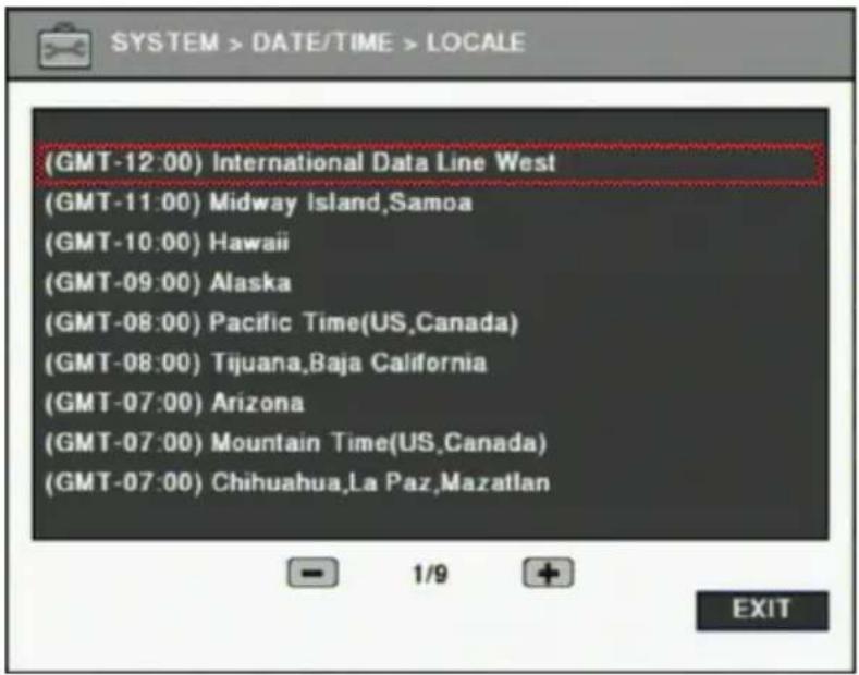
NTP SERVER: Used to set the internet time server.
※ Daylight saving time is applied automatically according to the corresponding location.
3 [Password]
- You can specify the password and authority of each user. The password can be set to a maximum of 20 digits.
- You can set authority for each camera, setup, search/backup, and PTZ control for each user.
- You can set the system to log out automatically. If there is no operation during the selected time, the system will log out automatically.
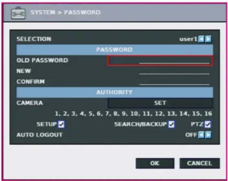
※ If you access as Admin account, previous password is not required. ✗ No authority setting is available for Admin account. ※ Only camera authority is allowed for Logout account. ✗ Logout screen setting is applied the same as for Spot-Out. ※ White screen will be shown for the cameras which are not set the authority.
4 [Initialize]
- You can initialize data and configuration by this menu.
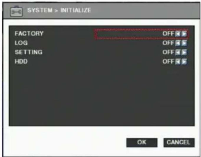
FACTORY: Delete entire data in the system and restore as factory default.
- The dialog box will be shown as below at the first booting after factory default setting.
- The text in the dialog box will be shown in English as default.
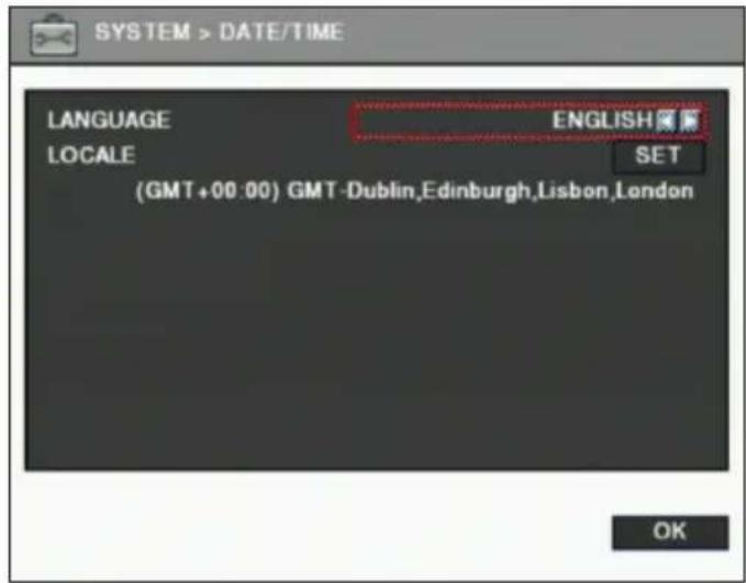
※ You can set time zone by clicking SET button, which is the same as [SYSTEM] → [DATE/TIME] menu.
LOG: Delete all event logs. - SETTING: Delete configuration settings. ■ HDD: Format HDD data.
![LG LE6016N-NH - [Initialize] - 3](/content/2026/05/919633/images/d2480c27a9405c10f32306662fcc0d802aa0c763dd02d90006d7be45fb0b3bc0.jpg)
NOTE
- If data is initialized, it cannot be recovered. Before using "initialize", important data must be backed up. • HDD Factory initialization formats the HDD and you will lose recorded data.
5 [Controller]
- Connect keyboard controller to DVR system.
- Setup configuration to access DVR with keyboard controller. (*Refer to controller user manual)
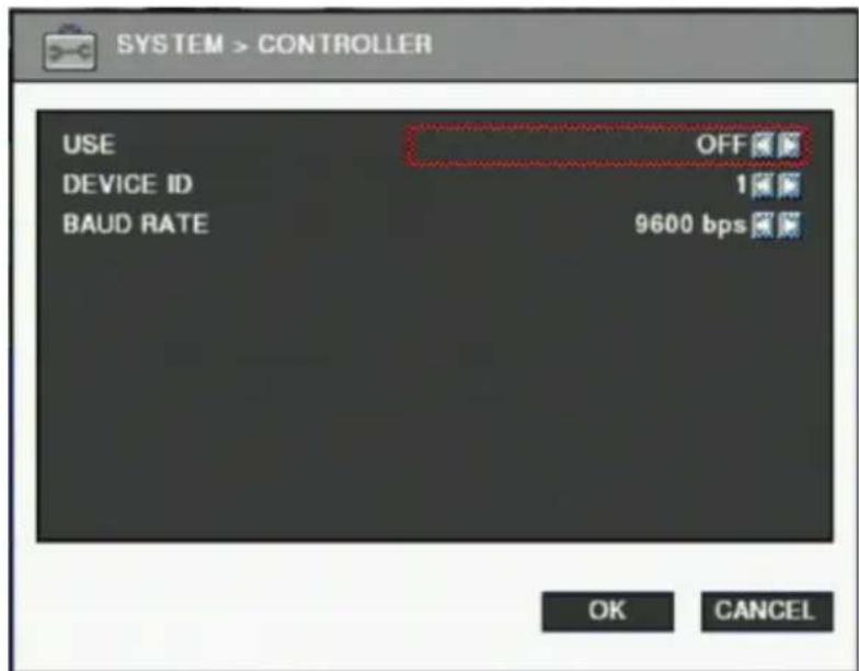
※ Supported device: LKD1000 Dynamic Controller (LG)
Camera
On the camera menu, channel, recording, schedule, color and PTZ can be configured.
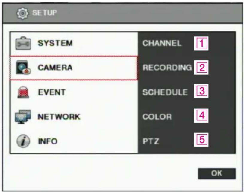
1 [Channel]
- You can specify channel name and audio for each camera.
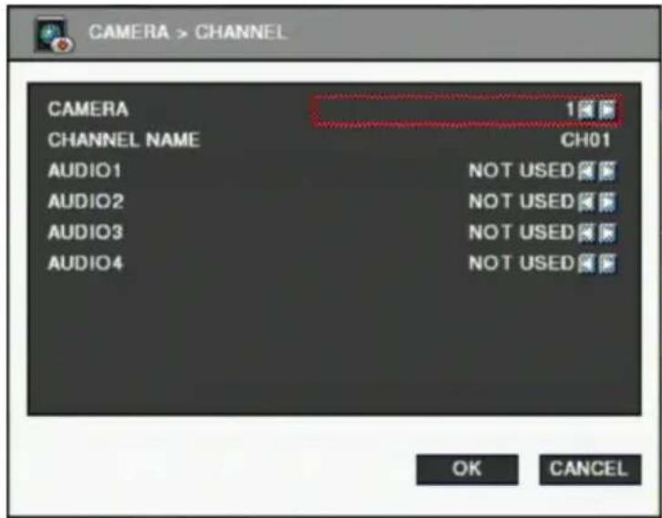
■ CAMERA: Select camera to change. CHANNEL NAME: Input channel name (Max 8 digits). AUDIO: Specify channel that audio is related to.
2 [Recording]
- You can specify recording configuration.
![CAMERA > RECORDING TOTAL FRAME [480/480] CAMERA 1 RESOLUTION CIF(352x240) FRAME 30 EVENT FRAME 30 QUALITY NORMAL APPLY ALL OK CANCEL](/content/2026/05/919633/images/63427451414904c59a9b1555ab54d140722f69d05b8c44a2703a4e2b111215fa.jpg)
TOTAL FRAME: Max frame rate is restricted by screen resolution. ■ CAMERA: Select camera to set frame and quality. ■ RESOLUTION: Specify screen resolution. (CIF / HALF D1 / D1) FRAME: You can specify recording frame rate when recording method is continuous for selected camera. ※ Frame rate cannot exceed event frame rate. ■ EVENT FRAME: You can specify recording frame rate when recording method is event for selected camera. QUALITY: Specify image quality for selected camera. (VERY HIGH, HIGH, NORMAL, LOW, VERY LOW) - Click "APPLY ALL" button to apply setting to all cameras.
3 [Schedule]
- You can specify recording method by schedule with date and time.
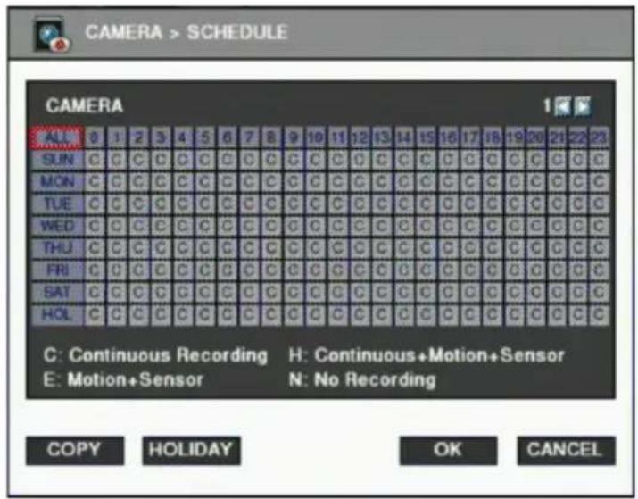
- Click time table to change recording method.
- Click channel number to change recording method for all time.
- Click time label to change recording method for all channel.
- Click "COPY" button to copy the settings for applying the current settings to the other channel(s).
C: Continuous recording method
H: Continuous recording + event recording method (Motion, Sensor)
E: Event recording method: if event (Motion, Sensor) happens, recording works.
N: No Recording.
- Click 'HOLIDAY' button to specify holidays.
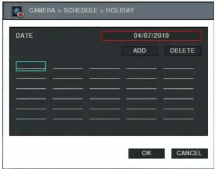
-You can select month and day by clicking date button.
- Click the Add button, the selected month and day will be added to the list of holidays.
-Click the Delete button to delete the selected date from list.
4 [Color]
- You can adjust brightness, contrast, saturation and hue.
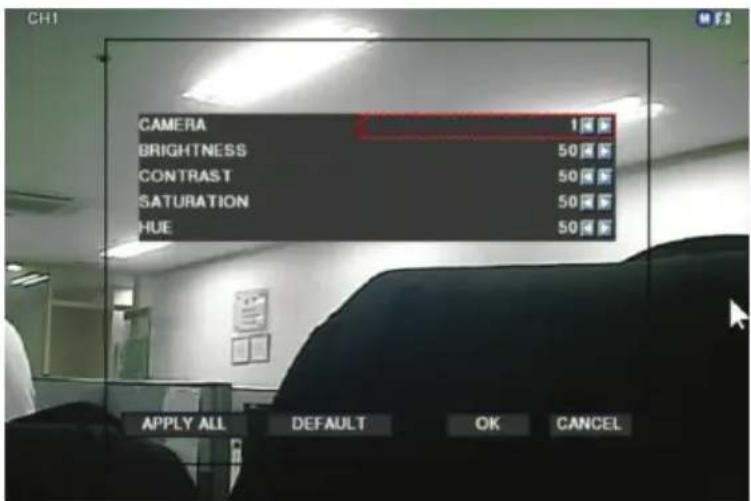
5 [PTZ]
• This is to setup the PTZ configuration.
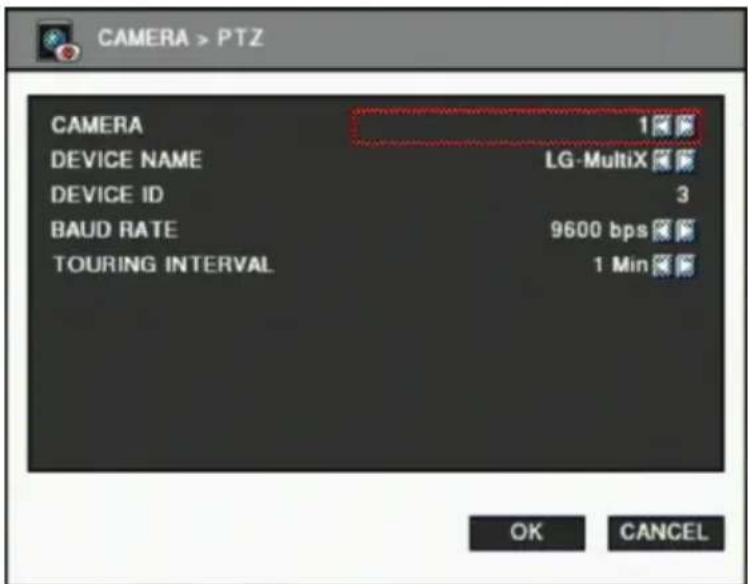
■ CAMERA : select camera to setup PTZ.
■ DEVICE NAME : Select camera name.(Max 15 cameras supported)
- LG Multix_E / LG Co., Ltd
- LG Multix / LG Co., Ltd
- LPT - A100L / LG Co., Ltd
- LVC-C100 / C200HM / LG Electric Inc
- HSDN251 / Honeywell Co., Ltd
- MD200 / 2000 / 1200 / 800 / Sony Co., Ltd
- New Born / NEW BORN HIGHTECH
- WVCS850 / Panasonic
- PELCO-D / PELCO Co., Ltd
- PELCO-P / PELCO Co., Ltd
- SAMSUNG_E / SAMSUNG Co., Ltd
- SPD-2300 / 3000 / 3300 / SAMSUNG Co., Ltd
- SUNGJIN / SUNGJIN Co., Ltd
- TPD7720 / DYNACOLOR, INC
- V1305R-DC / V1300RB / CRX - 1013 / VICON
■ DEVICE ID : Select ID that configured in camera.
BPS : Bit rate Per Second for data transmission. Default value of BPS is 9600
※ Value can be selected by camera setting: (1200/ 2400/ 4800/ 9600/ 19200/ 38400/ 57600/ 115200 bps)
TOURING INTERVAL: This is time interval before moving to next preset position when touring.
- Select one from 5 seconds, 10 seconds, 20 seconds, 30 seconds, 1 minute, 3 minutes and 5 minutes. • The default is 1 minute.
![LG LE6016N-NH - [PTZ] - 2](/content/2026/05/919633/images/bfede1cf35faa0d1e90a035c93bde281df8ce2edea34f0f3e37b3abf8a4ff841.jpg)
NOTE
Basically, DVR supports one RS-485 port for PTZ connection.
Event
You can specify the processing when an event occurs, such as sensor, motion detection, video loss, and the email notification settings when an event occurs.
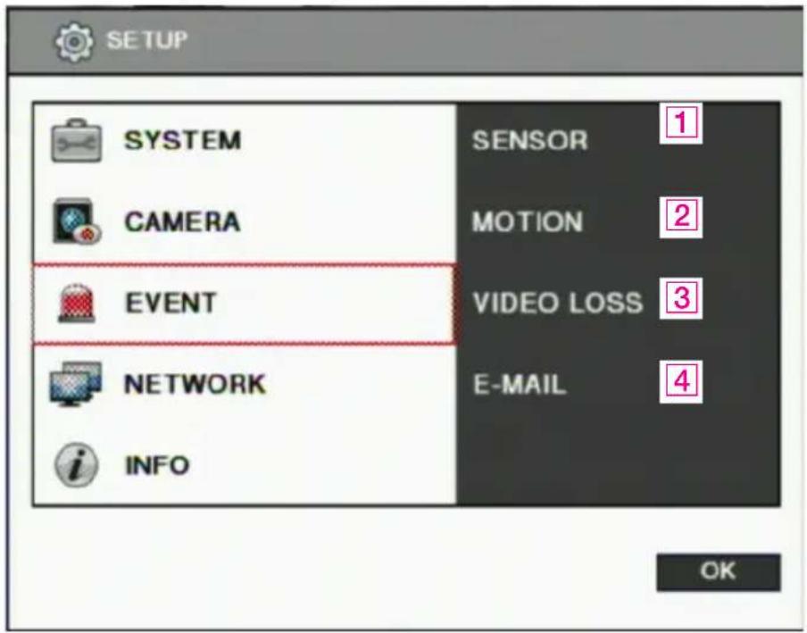
1 [Sensor]
- You can specify the processing when an event occurs from an input device.
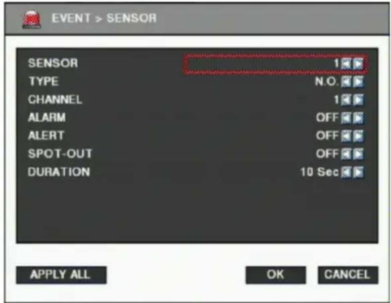
■ SENSOR: Selecting sensor number. (1 ~ 8) TYPE: Setting NO / NC type.
- NO (Normal Open): The type of input device is opened normally.
- NC (Normal Close): The type of output device is closed normally.
■ CHANNEL: Selecting associated channel with the sensor input. (OFF/1~16) ■ ALARM: Setting alarm out when event occurs from input device. (OFF/1~4) ■ ALERT: Setting sound a buzzer when event occurs from input device. (ON/OFF) ■ SPOT-OUT: Setting spot out when event occurs from input device. (ON/OFF) ■ DURATION: Setting the duration time from event occurs. (1~10 Sec., OFF)
2 [Motion detection]
- You can specify the process when motion is detected.
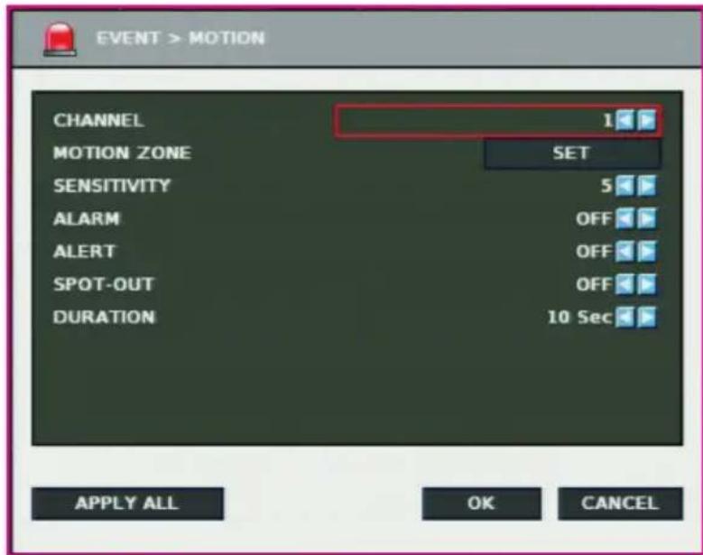
CHANNEL: Selecting camera which is associated event. ■ MOTION ZONE: Setting the motion detection zone.
-Click "SET" button to setting motion detection zone.
-The red-marked area is set as motion detection zone.
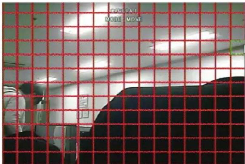
-Click right button of mouse on the screen to display menu window.
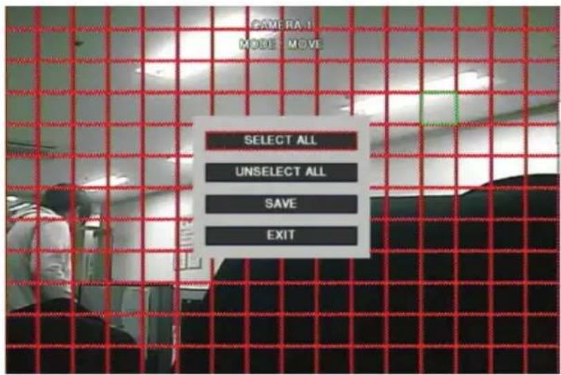
SELECT ALL: Selecting entire area. UNSELECT ALL: Unselecting entire area. SAVE: Saving selected area as a motion detection zone. EXIT: Exiting motion zone setting.
■ SENSITIVITY: Setting the motion sensitivity. (1 to 10) ■ ALARM: Setting alarm out when motion is detected. ■ ALERT: Setting sound a buzzer when motion is detected. ■ SPOT-OUT: Setting spot out when motion is detected. ■ DURATION: Setting the duration time from motion detection occurs.
3 [Video loss]
- You can specify the processing when video loss occurs.
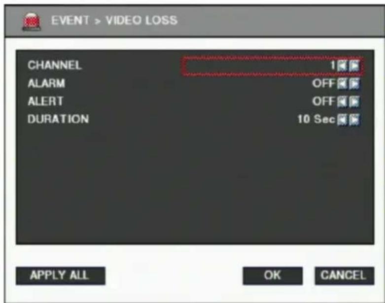
CHANNEL: Selecting the camera associated with the event. (1~16) ■ ALARM: Setting alarm output when video loss occurs. (OFF/1~4)
■ ALERT: Setting a buzzer sound when video loss occurs. (ON/OFF) ■ DURATION: Setting the duration time from video loss. (OFF/1~10 Sec.)
4 [E-mail]
- You can set the E-mail notification when an event occurs.
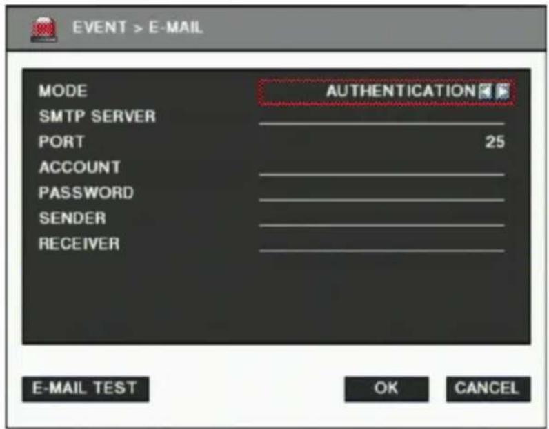
■ MODE: Enabling or disabling E-mail notification. (OFF / Authentication / Not authentication) ■ SMTP SERVER: Setting the IP address or domain name of the SMTP server. ■ PORT: Setting the TCP port number of SMTP (Default value is 25). ■ ACCOUNT: Setting the E-mail account registered in the SMTP server. ■ PASSWORD: Setting the password of the E-mail account. ■ SENDER: Setting the E-mail address of the sender. RECEIVER: Setting the E-mail address of the receiver. E-MAIL TEST: Click to send a test E-mail, then the RECEIVER can check the test E-mail.
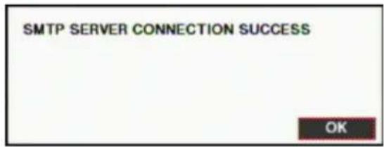
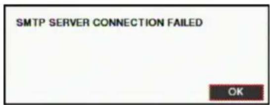
※ SMTP server does not support encrypted E-mail protocol.
Network
You can set the network environments.
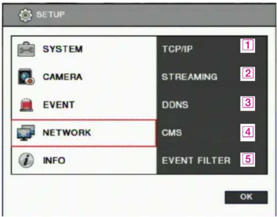
1 [TCP/IP]
- You can specify the TCP/IP setting according to the network environment.
- Specifying the TCP port numbers for Web, Playback, and Live.
- Default values: Web(80), Playback(9091), Live(9092)
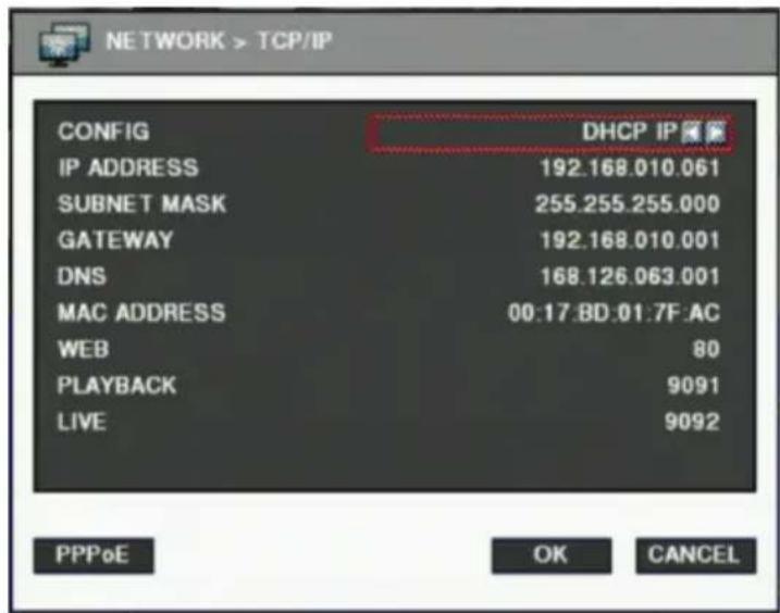
For dynamic IP or PPPoE
- All the items of IP address, subnet mask, gateway and DNS are disabled and set each value automatically.
- You can specify account and password of PPPoE using PPPoE button which is located left below.
For static IP
IP ADDRESS : Enter IP address received from ISP using screen keyboard. SUBNET MASK : Enter subnet mask received from ISP using screen keyboard. GATEWAY : Enter gateway received from ISP using screen keyboard. DNS : Enter the DNS IP address received from ISP using screen keyboard. MAC ADDRESS : This is hardware specific unique address of network device, so user cannot set this value. 8000~65535 port number is recommended. Do not use the same port number with each other. web(80), playback(9091), live(9092), CMS LG(9100) If the network of DVR is connected via router, you must set Configuration of port forwarding according to the router. (web, search, live ports) Please refer to user's guide of the router which you are using.
2 [Streaming]
- You can set each item about the network video streaming.
![NETWORK > STREAMING TOTAL FRAME [120/120] CAMERA 1 FRAME 7.5 QUALITY NORMAL APPLY ALL OK CANCEL](/content/2026/05/919633/images/55706981d90f3c63e230b027e54114a35619adea8af32941f79e08a267dfa93d.jpg)
TOTAL FRAME: : Total frame rate set / Maximum available frame rate CAMERA: Selecting camera. FRAME: Frame rate per a second for each camera QUALITY: Selecting video encoding quality (VERY HIGH, HIGH, NORMAL, LOW, VERY LOW) Click "APPLY ALL" button to apply setting to all cameras.
3 [DDNS]
- You can use DDNS service provided by LG.
- You can connect to DVR easily using host name instead of IP address with LG DDNS
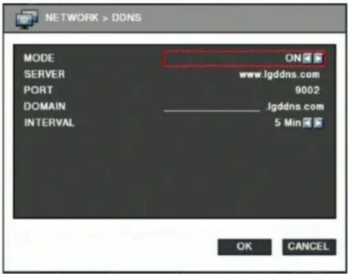
MODE : Enabling or disabling DDNS. SERVER : IP address of DDNS. PORT : TCP port number of DDNS. DOMAIN : The domain name of DVR device. INTERVAL : Setting the interval of IP address updating.
4 [CMS]
- Specifying IP address and TCP port number of CMS.
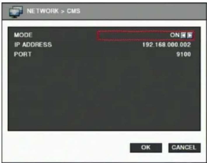
MODE : Enabling or disabling event report to the central monitoring center when event occurs. IP ADDRESS : The IP address of the central monitoring center.
PORT : The TCP port number of the central monitoring center.
※ 8000~65535 port number is recommended. ✗ Do not use the same port number with each other. web(80), playback(9091), live(9092), CMS LG(9100)
5 [Event filter]
- Specifying the event which will be sent to the central monitoring center and E-mail.
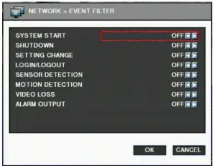
■ SYSTEM START : Enabling or disabling the system start event. SHUTDOWN : Enabling or disabling the system shutdown event. ■ SETTING CHANGE : Enabling or disabling the setting change event. - LOGIN / LOGOUT : Enabling or disabling the login / logout event. ■ SENSOR DETECTION : Enabling or disabling the sensor detection event. ■ MOTION DETECTION : Enabling or disabling the motion detection event. ■ VIDEO LOSS : Enabling or disabling the video loss event. ■ ALARM OUTPUT : Enabling or disabling the alarm output event.
Information
You can view the general system information and run software update.
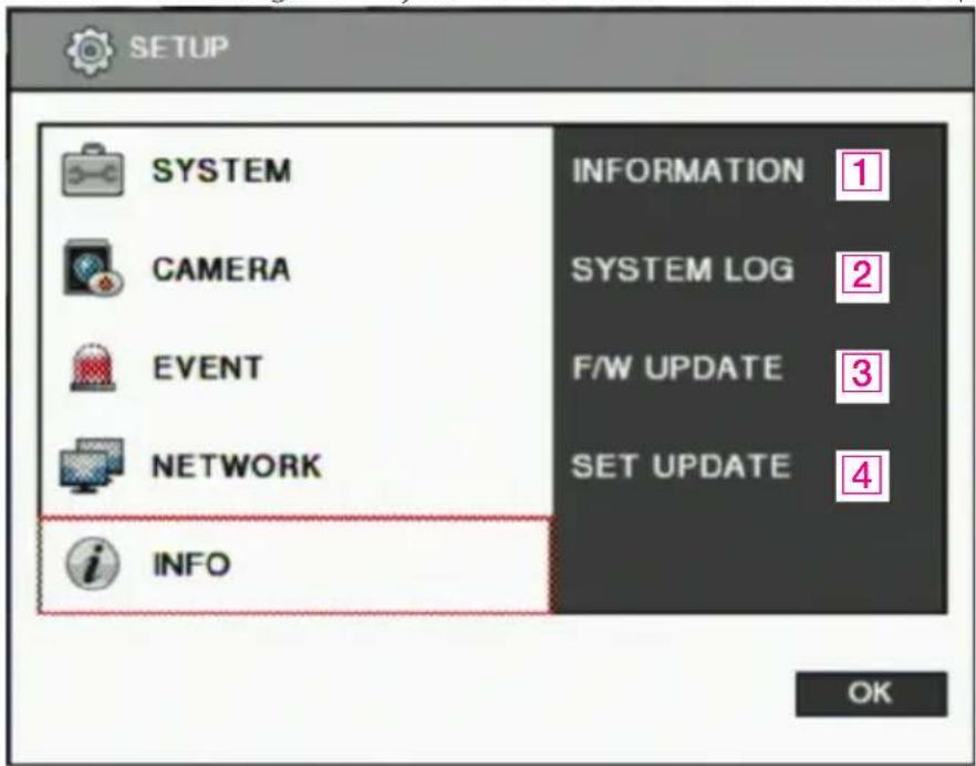
1 [System information]
- You can view the system information.
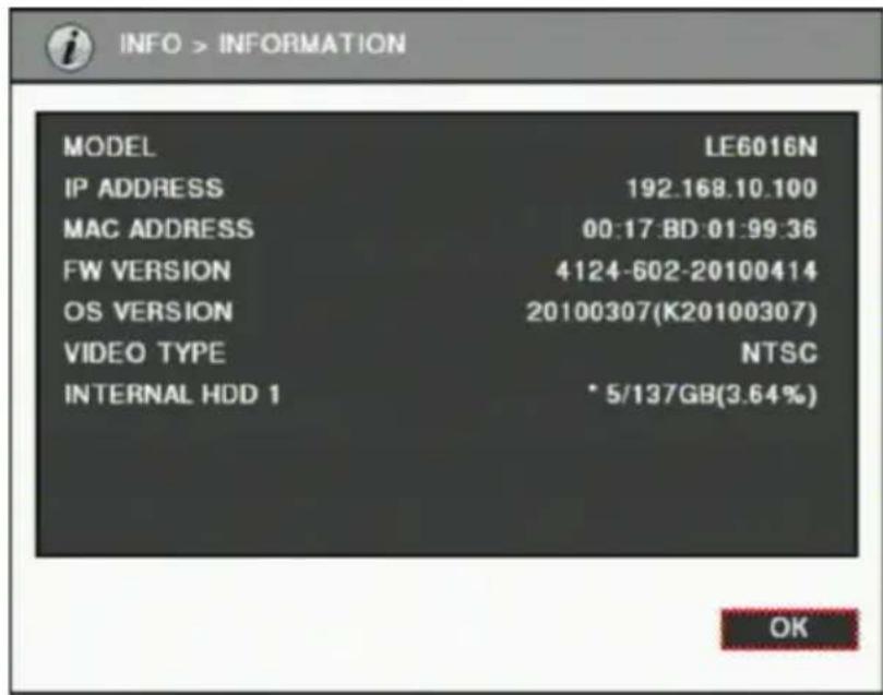
■ MODEL : Model name of the device. IP ADDRESS : The IP address assigned to the device. MAC ADDRESS : The MAC address assigned to the device. F/W VERSION : The version number of firmware. OS VERSION : The version number of Operating system.
■ VIDEO TYPE : Showing NTSC or PAL. This is set automatically by detecting incoming video signal, so user cannot change this value. ■ HDD: HDD capacity, using ratio and status.
-* mark is shown at the HDD which is currently recording. - "NOT HEALTHY" is shown according to the HDD status. -The HDD connected to E-SATA port is displayed as "External HDD".
2 [System log]
- You can view the system log. (Refer to page 26 [System log])
3 [F/W Update]
- You can run firmware update.
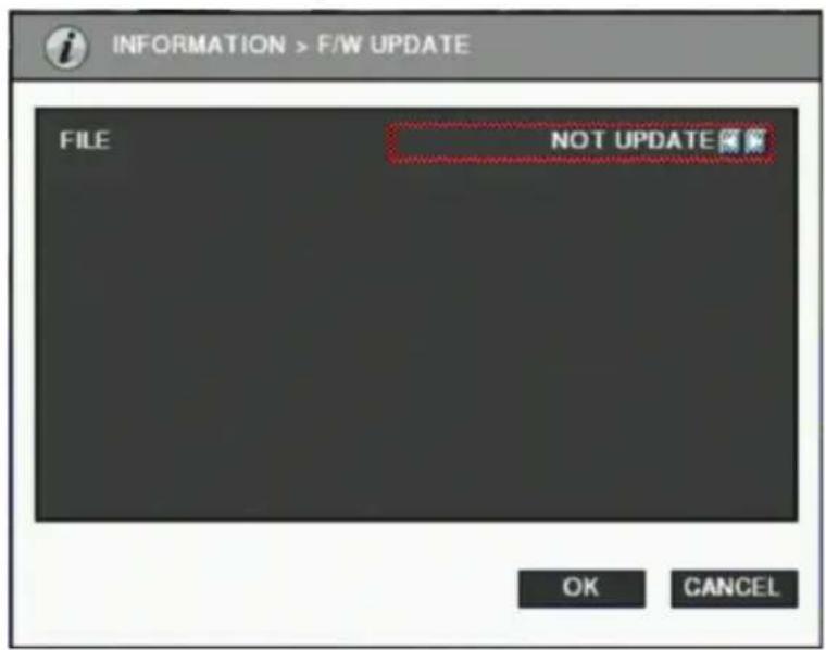
FILE: You can specify the firmware file to update using the ◀ / ▶ buttons.
4 [Setting update]
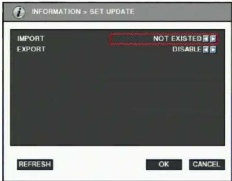
IMPORT: You can replace current setting values with new values from USB memory. (ENABLE/DISABLE) EXPORT: You can export current setting values to USB memory. (ENABLE/DISABLE)
![LG LE6016N-NH - [Setting update] - 2](/content/2026/05/919633/images/8db08d15262b88793f3343947b74f6803e2e8030e450aad178c42aeed043f656.jpg)
NOTE
A USB memory stick is needed to update firmware or settings. It takes about 5 seconds to recognize the USB memory device after it is connected. The message "USB is not detected." will be shown when you try to run a backup without a connected USB.
3-4. PTZ Control
This is used to control a PTZ camera connected to the RS-485 port. Camera and DVR settings should be done if you want to control the PTZ camera.
- Click the icon

to control PTZ.
- Control the PTZ camera using each item below.
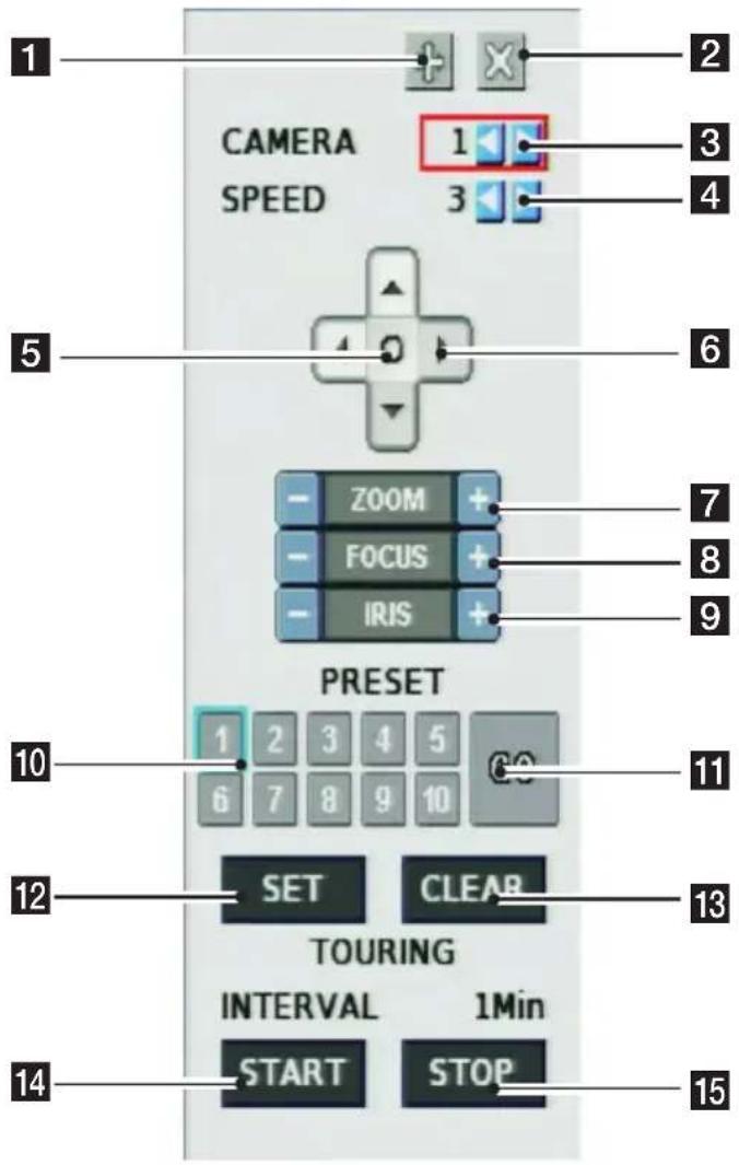
1 Click to move the PTZ control window. 2 Click this button to close the PTZ control window. 3 Click this spin control to select the PTZ camera. (1~16) 4 Click this spin control to specify the moving speed of the PTZ camera (1~6). 5 Click this button to show the OSD menu of the camera. 6 Click these direction buttons to pan or tilt the camera. 7 Click to control zoom in or out.
8 Click to control the focus of the camera manually. 9 Click to control the iris of the camera manually. 10 Click to select a preset number. 11 Click to move to the selected preset position. 12 Click to set the current position as a new preset position. 13 Click to delete a specified preset number. 14 Click to start touring, which traverses each preset position one by one according to dwell time. 15 Click to stop touring.
Setting a new preset position
- Move the camera position using direction button 6.
- Select the preset number to set using button 10.
- Click button 12 "SET".
- Repeat steps 1 to 3 to set another preset position. ※ Up to 10 preset numbers are available. ※ The maximum preset number varies depending on the camera's specifications.
■ Moving the camera to a preset position
- Select the preset number to move to using button 10.
- Click button 11 "GO". ✗ Moving the camera to a preset position is only available when the camera supports the preset feature.
- Deleting a preset position
- Select the preset number to delete using preset number button 10.
- Click button 13 "CLEAR". ✗ Deleting a preset position is only available when the camera supports it.
Starting touring
- Click button 14 "START".
- Then it will automatically start traversing each preset position one by one.
Stopping touring
- Click button 15 "STOP".
- Then it will stop traversing.
- Click button 15 "STOP".
- Then it will stop traversing.

NOTE
• The tour which is working will be stopped after the setting is changed. - If you control the Camera OSD by using the SAMSUNG E protocol to select the exit(X) menu, the DVR may not operate normally. In this case, you can recover the system by inputting the Zoom +/- key after inputting the O key of the OSD.
3-5. Search (Playback) & Backup
Various features are available for user to search recorded data easily.
Time search
You can search recorded data with date and time.
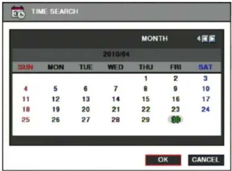
Search method
A. Click button on menu bar of real time screen. B. Select the date you want to search on the calendar above and click "OK". (The date with recorded data is displayed in bold.) C. Then recorded time table will be displayed. (Refer to the image below) D. The recorded data will be displayed after you select time and click "OK" button.
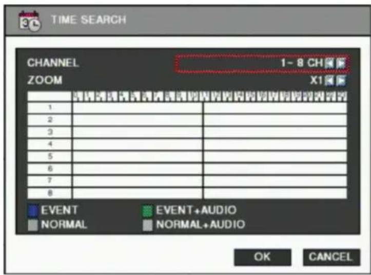
✗ Click the "CANCEL" button to select date again. ※ You can select a data if data are duplicated at the same time stamp using spin box below. The spin box is shown only when data are duplicated at the same time stamp, which is caused when daylight saving period. ※ Bigger number of duplicated data stands for more recent data.
Event Search
You can search recorded data using event occurrence time.
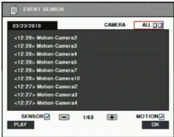
A. Click the mouse on the icon in the menu bar located at the bottom of the search mode screen. B. Use the ◀▶ buttons on the upper right side to select the camera to search. C. Check the sensor and motion check boxes below to filter out events. D. Move to the previous or next page using the - and + buttons.
E. Select a data entry to search from the list. Click the mouse button to move to the corresponding recorded data.
F. Click the "PLAY" button and the searched data will be played.
Bookmark
You can access the bookmarked time directly without going through the search.
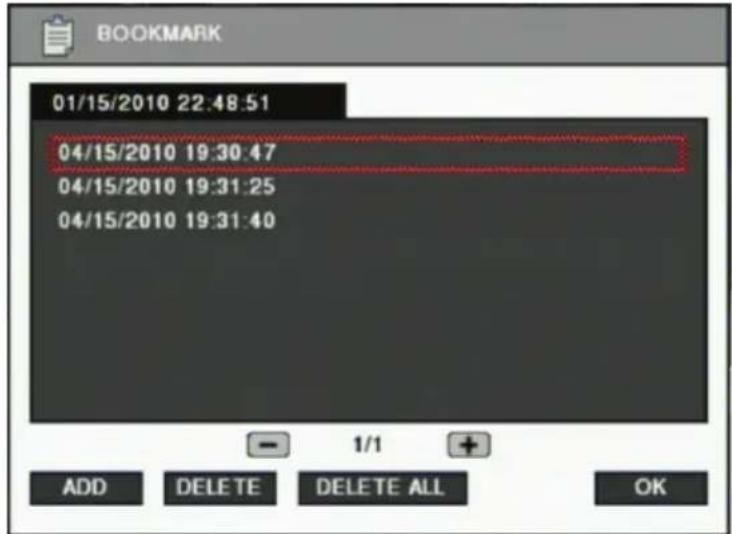
ADD
- Use the time search and place you want to add a bookmark.
- Click the mouse on the icon.
- If you want to add the current selected time, click the Add button. Bookmarks can be added up to 100.
SEARCH
- Click the mouse on the icon.
- Use the "+" and "-" buttons to move the page using a bookmark, then select the item you want to move to.
DELETE
- Click the mouse on the icon.
- After you select an item, click the Delete button to delete it. If you want to delete the entire entry, click DELETE ALL.
Backup
You can back up the recorded data for the selected date/time and channels.
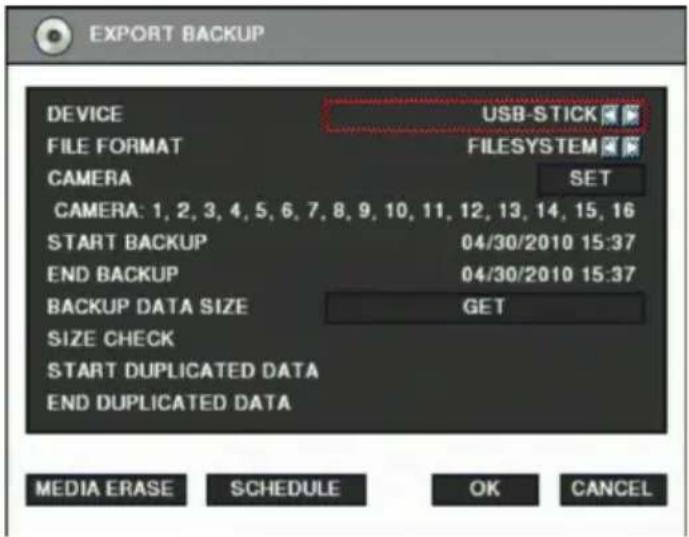
A. Click the mouse on the icon in the menu bar located at the bottom of the screen. B. Select a device to store the backup data. Only USB-STICK is available for LE6016N. USB-STICK, CD-RW, or DVD-RW can be used for LE6016D. C. Select media type. If you select FILESYSTEM, backup data will be stored in native format with a backup player. If you select AVI, only one channel is backed up. D. If you want to select the camera for backup, click the "SET" button and select the cameras you want. On the other hand, when AVI is selected, only one camera can be selected. E. It displays the selected cameras. (CAMERA: 1,2,3,4,5,6,7,8,9,10,11,12,13,14,15,16) F. Specify the starting date/time of the backup period. G. Specify the ending date/time of the backup period. H. Check the data size to back up. But when AVI is selected, only one camera can be selected. I. If duplicated data exists in the backup data period, select one data from "START DUPLICATED DATA" or "END DUPLICATED DATA". J. After finishing the backup settings, click the OK button. K. When backup is started, the screen moves from search to real-time live mode, and the icon and text will be shown as below to display backup progress.
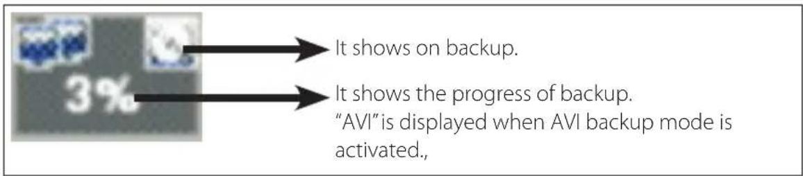
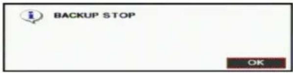
L. The message "BACKUP STOP" will be shown when backup is finished.
- You can back up automatically daily based on a schedule backup.
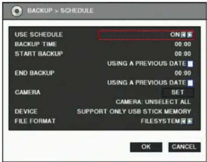
A. If you are to use schedule backup, set "USE SCHEDULE" to "ON". B. Enter the time to execute backup at "BACKUP TIME". If the USB memory stick is not connected or has no free space, backup cannot be executed. C. Enter the start time of the backup period at "START BACKUP". Check "USING A PREVIOUS DATE" if needed. D. Enter the end time of the backup period at "END BACKUP". Check "USING A PREVIOUS DATE" if needed. E. If you want to select cameras to back up, click the "SET" button at "CAMERA" and then select cameras. On the other hand, in case of AVI backup, only one camera can be used. F. Selected cameras are shown. (CAMERA: 1,2,3,4,5,6,7,8,9,10,11,12,13,14,15,16) G. Select data format. When selecting "FILESYSTEM", the native backup player is included as well, so you can search and playback easily with it. H. Click the "OK" button after finishing settings. When the set time at "BACKUP TIME" is reached, the backup will be executed automatically.
✗ Schedule backup will be executed repeatedly once a day.
How to cancel backup
If you press the 📋 button while backup is running, the selection message will be shown as below.
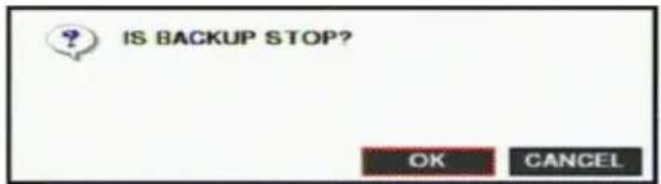
→ Click "OK" to cancel the backup.
MEDIA ERASE
→ You can erase data in the storage media, such as a USB memory stick, CD-RW, or DVD-RW. When using a USB memory stick, connect it to the USB port on the front side, then click the "MEDIA ERASE" button to erase data. It is recommended to back up important data stored on the USB storage before using this function. When using a CD-RW or DVD-RW, insert the media into the DVD recorder, then click the "MEDIA ERASE" button to erase data.
※ The backup process will not start if you specify an invalid starting and ending date/time. ✗ The backup period cannot exceed 24 hours. ✗ The USB memory stick should be formatted as FAT32. When performing an AVI backup, if there are different resolutions or frame rates, the AVI files are separated at each change point. The maximum size of backup data depends on the storage media used. For USB memory sticks, only free space is used (but for AVI backup, the maximum file size is limited to 2GB). For CD-RW, up to 700MB, and for DVD-RW, up to 4.7GB. ✗ In the case of FILE-SYSTEM backup, data files are separated into 127MB units, while a single file is used for AVI backup. ※ If data already exists on the CD-RW or DVD-RW media, the old data will be removed and new data will be written. ✗ If there is duplicated data at the same time stamp, you can select the specific data position using the dialog box below. Select the data position with the spin box, then click "OK" to start the backup. The older data has a smaller number. ✗ Other functions do not work while backup is running.
✗ A larger number for duplicated data indicates more recent data.

NOTE
Do not remove the external USB device while backup is running.
- Backup data playback
The backup data on USB storage or CD/DVD media can be played on a PC.
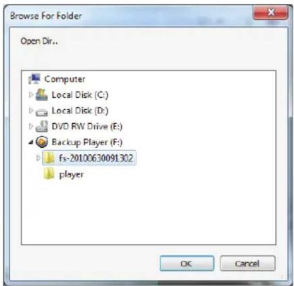
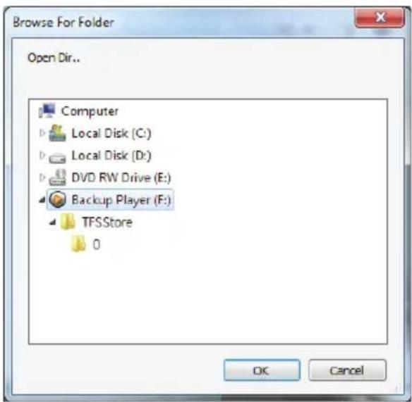
A. The backup player software will run automatically when you insert the media containing backup data into the PC. If the backup player does not run automatically, due to the PC's security settings, you should run it manually. For USB storage, it is located at "\player\player.exe", and for CD/DVD, it is located at "\player.exe". B. Specify the folder containing the backup data. For USB storage, the folder name consists of "fs-[backup date/time]", and for CD/DVD, just select the disk drive. C. After specifying the data folder, click "OK", and the backup data will be played.
• System log backup
The system log information will be saved in a text file format in the backup data folder. When the backup is in progress, the system log is saved from the backup start date/time to the backup end date/time at the same time.
4
Web viewer
4-1. Installation
Set up the network before the installation.
Web viewer installation
- Enter the LG DVR IP address in the Web address window, and then the following Active X installation window will be displayed.
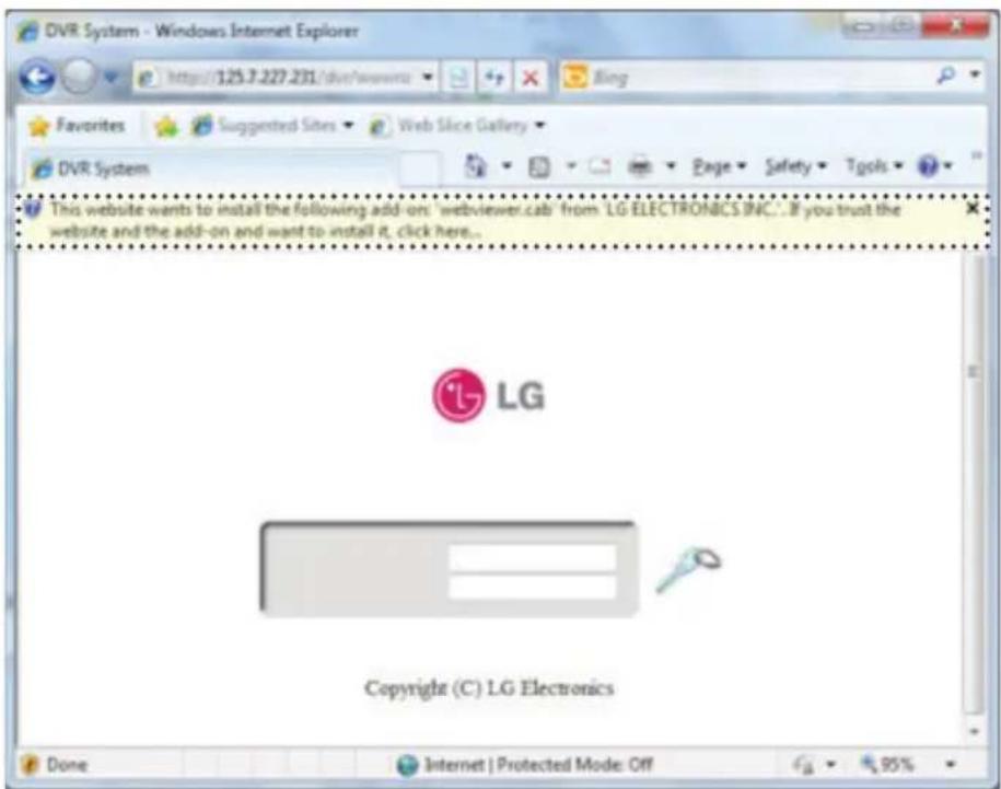
- When you click on the Active X install button, the following window will be displayed. Press the Install button.

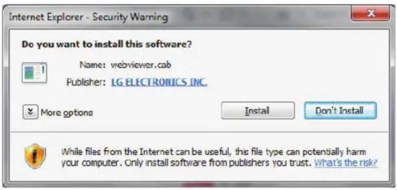
- Press the Next button from the Web View installation window. When the installation is completed, the Web initialization screen will be displayed. (General installation recommended)
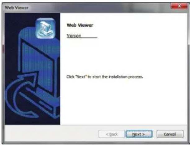
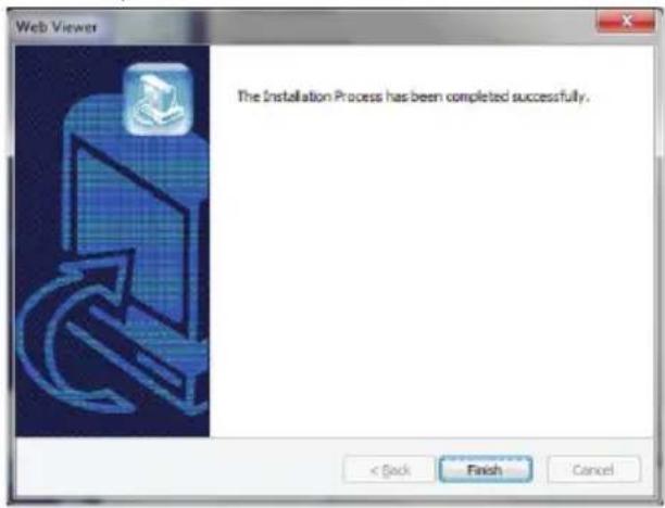
- Enter the ID and password. (Multi-login is not enabled for admin user ID.) (Default: admin, user1, user2, user3)
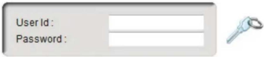

NOTE
Web Viewer and CMS LG cannot be used at the same time.
4-2. Functional description
Web viewer monitoring window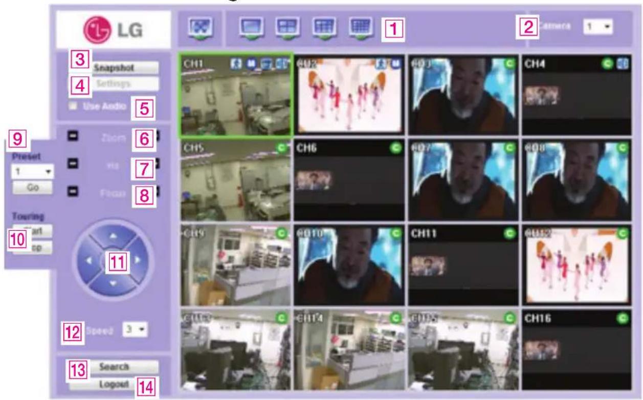
1 Divide screen division (Full screen/1/4/9/16) 2 Selecting a camera 3 Real time image capture (Save as JPEG) 4 Settings (It is available only when you logged in as admin) 5 Enable or disable incoming audio (Default value is disable.) 6 Zoom control 7 Iris control 8 Focus control 9 Preset (Click "Go" button after selecting preset number at combo box) 10 Start/Stop touring (Rotation between each preset positions) ✗ Preset and touring are available after preset is set on the device. 11 Pan tilt control (Up, down, left and right buttons) 12 Controlling moving speed when pan tilt operation 13 Switching to search window 14 Logout
Web viewer search window
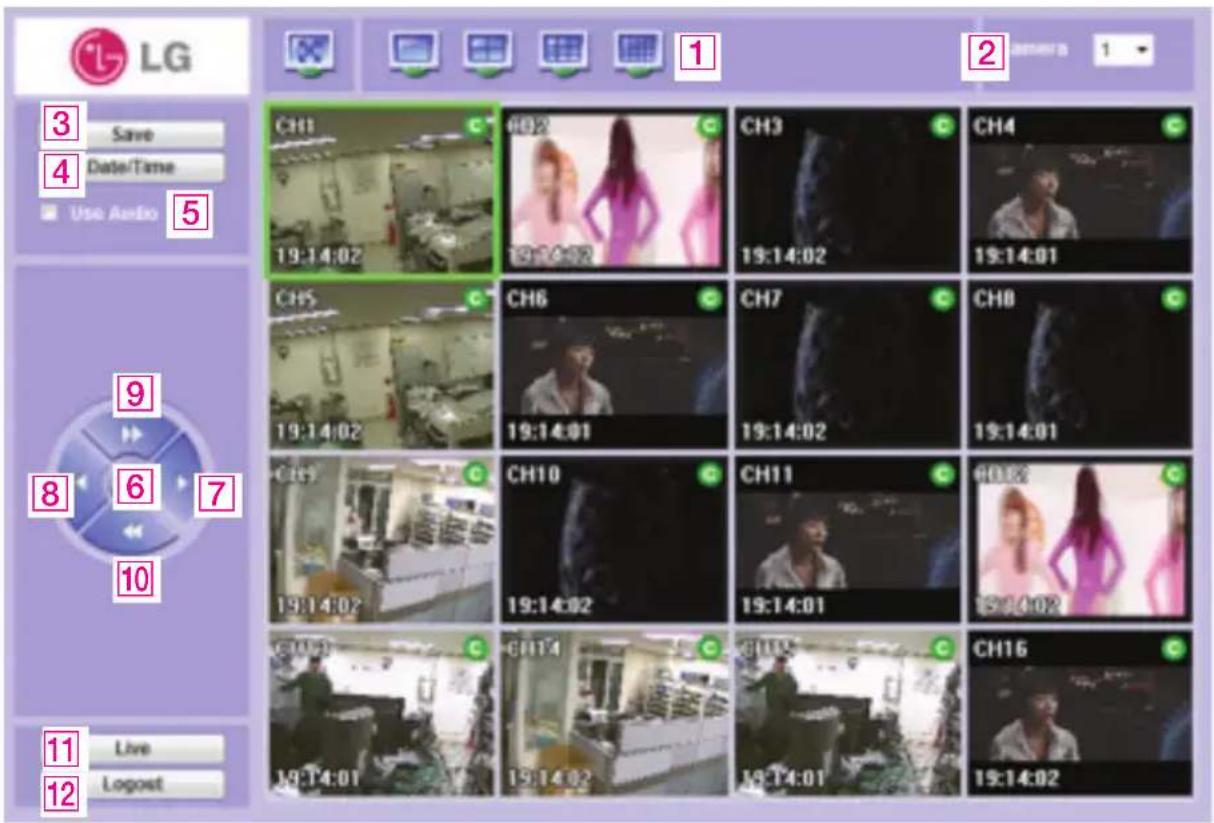
1 Divide screen division (Full screen/1/4/9/16) 2 Selecting a camera 3 Saving video or still image (Saving as AVI/JPEG/BMP) 4 Date/Time selection button to play back (Refer to "Search dialog box") 5 Enable or disable incoming audio (Default value is disabled.) 6 Pause button 7 Forward play button 8 Backward play button (Displaying only key-frame) 9 Fast forward play button 10 Fast backward play button 11 Switching to monitor window 12 Logout
Search dialog box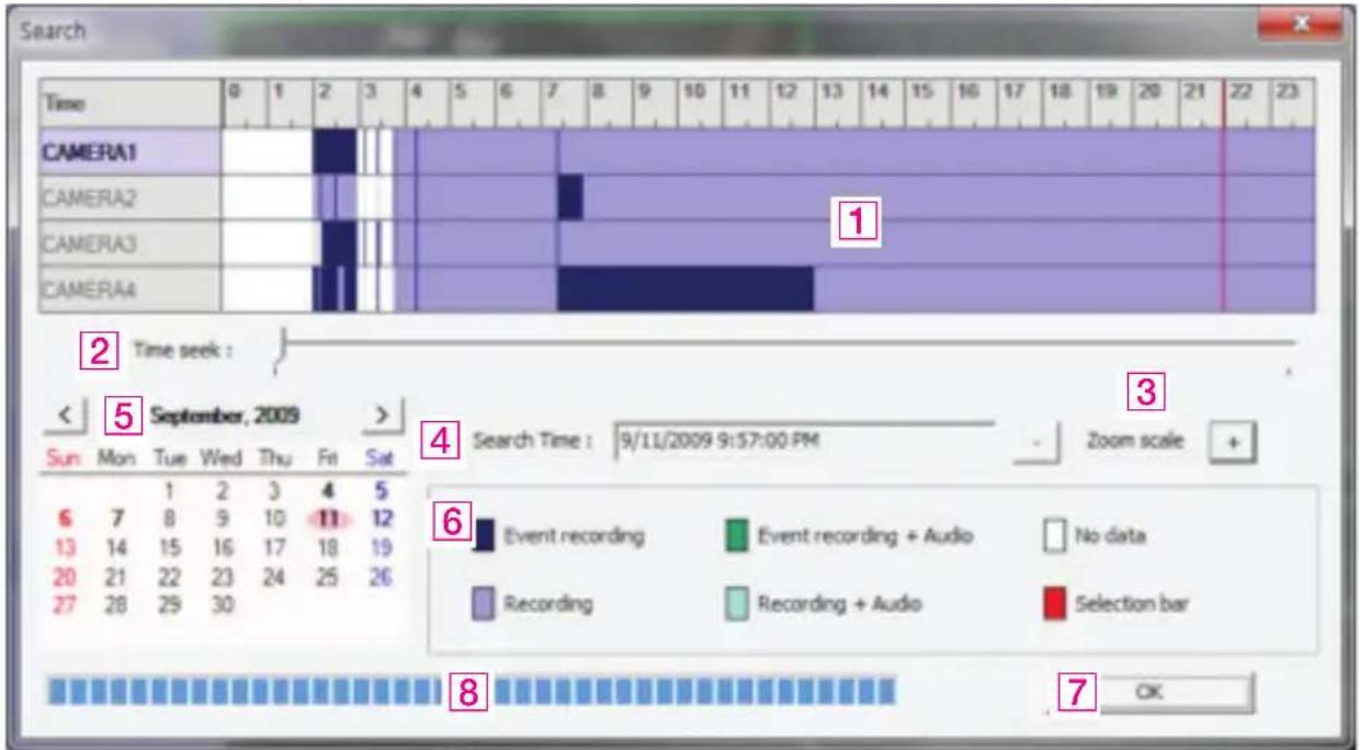
1 Recorded data graph (Click on the data graph to select time to play.) 2 Time scroll bar 3 Zoom in/out of graph (It can be scaled from 2 hours to 24 hours by minute unit.) 4 Displaying selected data/time 5 Displaying calendar (The dates are shown in bold if recorded data exist.) 6 Description of the color of the recorded data graph 7 "OK" button (Video is played immediately when you selected data/time which has recorded data.) 8 Progress bar which shows loading progress.
Saving as AVI file dialog box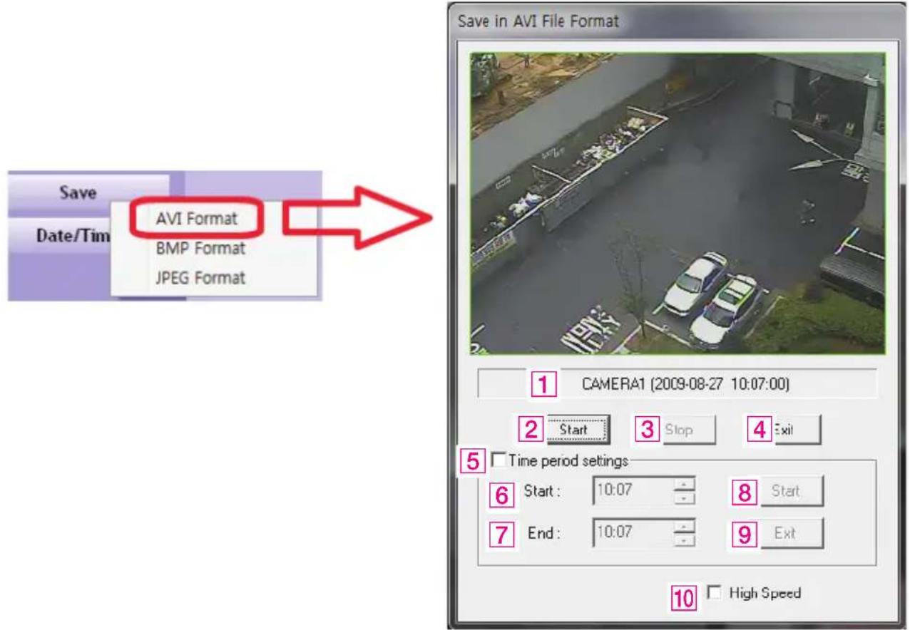
1 Camera name/Date/Time which is currently displayed. 2 Starting AVI saving (File name is requested when you click on this button.) 3 Stopping AVI saving 4 Closing Save as AVI dialog box (It will be closed automatically after stopping AVI file if it is being saved.) 5 Specifying time period to save AVI file. 6 Starting time to save AVI file. 7 Stopping time to save AVI file. 8 Starting periodic AVI file saving 9 Closing after finishing AVI file saving. 10 Increasing AVI saving speed with reducing displaying frame rate.
5
Apple iPhone/iPod
5-1. Functional description
Real-time monitoring
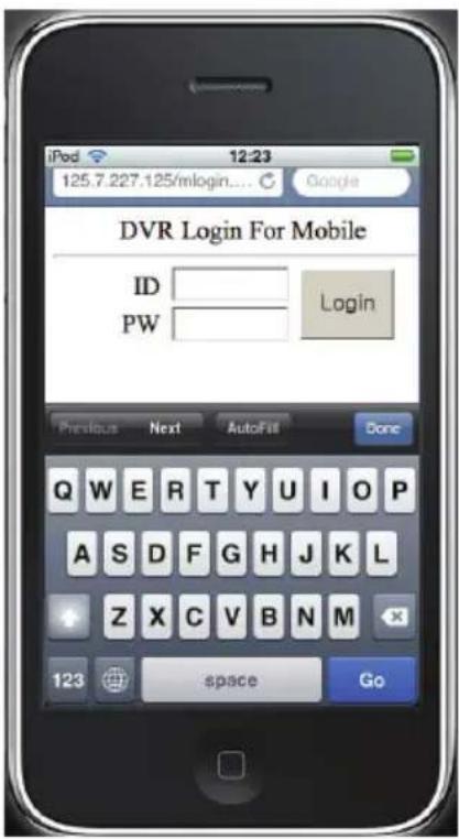
If you can use Wi-Fi environments, you can view the real-time monitoring video from DVR with iPhone/iPod.
- Run web browser at iPhone/iPod, and enter LG DVR IP address.
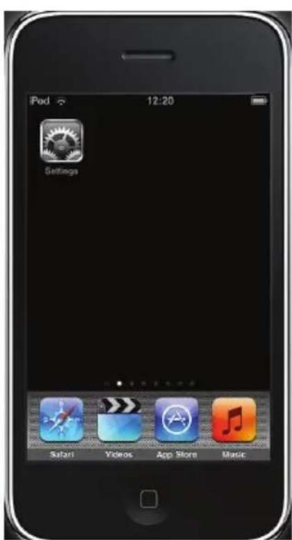
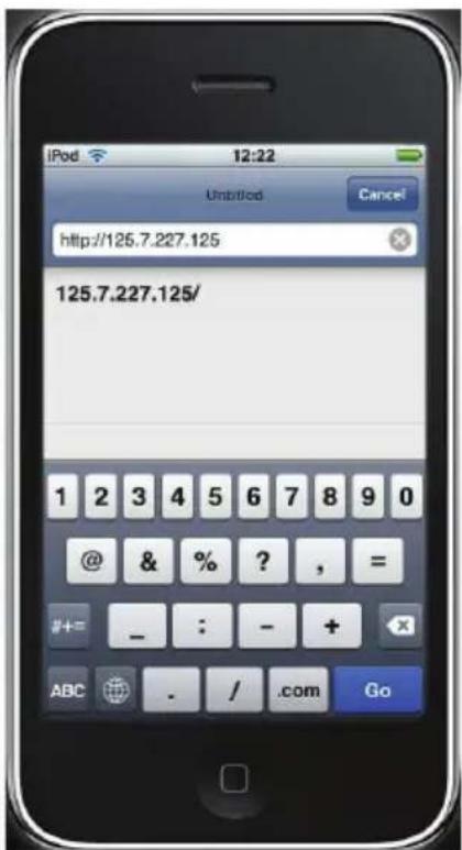
- Enter id and password, and click "login" button the real-time monitoring screen will be shown.
- Real-time monitoring screen.
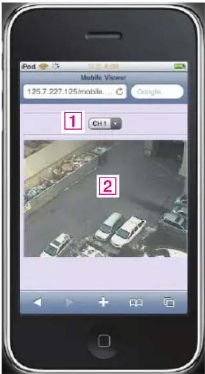
1 Camera selection (CH1\~16)
2 Video screen
6
Reference
6-1. Check before requesting for service
If the following symptoms are observed when using the product, recheck the following. It may not be a problem.
| Symptom Checkpoint and resolution | |
| I cannot turn on the power of the device | Check whether the power plug is correctly plugged. |
| Check whether the voltage of the power supply is correct. | |
| If the power cannot be turned even when the power of the device is connected correctly, please contact your closest service center | |
| The power of the device is turned on, but the screen on the monitor is not turned on | Check whether the power plug is correctly plugged. |
| Check whether the monitor is turned on. | |
| Check whether the video cable between the monitor and device is connected correctly. | |
| Check the selected monitor type. | |
| Try disconnecting the power plug, and then plugging it again. | |
| Camera number is displayed on the screen but the video of the camera is not displayed | Check whether the video output port of the camera is correctly connected to the device. |
| Check whether the power supply of the camera is connected correctly. | |
| Check whether the resolution is set to 1024x768 in VGA environment setting. | |
| Check if there is any issue with the video cable between the device and the camera. | |
| Reboot this device. | |
| Video of camera is displayed on the screen but I cannot record the video through the device | Check the recording setting from the recording setting menu. |
| Check whether the hard disk is recognized from the system information window. | |
| If the hard disk is not recognized normally, check the format and connected condition of the hard disk. | |
| Check the available space on the hard disk. | |
| I cannot search the recorded video. | During the search, check whether the video data currently being recorded exists. |
| If the video data currently being recorded does not exist, check the recording setting of the menu. | |
| Check whether the hard disk is recognized from the system information window. | |
| If the hard disk is not recognized normally, check the format and connected condition of the hard disk. | |
| I cannot hear the audio recorded with the video. | Check whether the recording audio channel is correctly set up. |
| Check whether the connector on the rear side of the device is connected with external device (Line input) correctly. | |
| Check whether the connected external device is operating correctly. | |
| Screen colors of some cameras are incorrect or the video is displayed in abnormal way. | If there is an object in the camera connected to the system, connect the camera to the video input port to check the video and check if there is any issue with the existing cameras connected to the system. |
| Check whether the video format of the device is the same as that of the camera. | |
| The video format can differ by the region into PAL or NTSC format. IF the video format of the device is not the same as that of the camera, the video may not be recognized. | |
| There is noise in the video. | If there is an issue with the camera connected to the system, connect a different camera to the video input port to check whether the existing camera connected to the system has an issue. |
| Check whether the video cable connecting the device and the camera is damaged. | |
| Check whether there is a cable with high voltage near the video cable. It can cause noise in the video or cause deterioration in the video quality. | |
| Check whether the video cable connected between the device and the camera is the cable for correct usage. | |
| If the power cable is used for the usage of video cable, it can cause noises in the video. | |
| The sensor connected to the device is not working. | Check whether the sensor type set in the sensor setting menu is the same as that of the sensor. |
| From the schedule management item of the recording setting menu, check whether the recording using the sensor is set up. | |
| Check whether the sensor is correctly connected to the ALARM-IN port. | |
| PTZ camera connected to the device is not working. | Check whether the PTZ camera is correctly set up from the camera setting menu. |
| Check whether the power cord of the PTZ camera connected to the system is correctly connected. | |
| Check whether the signal cord connected to the PTZ camera connected to the system is correctly connected. | |
| Check the channel the PTZ camera connected to the system controls. | |
| Check the user type. General user cannot use the PTZ function. | |
| I cannot receive the E-mail sent from the device. | When the E-mail transmission fails without SMTP server setting.·Check whether the network is set up correctly.·Check whether the E-mail address is entered correctly.·Check the spam mail setting for the entered E-mail address.(If the spam mail is set, some mails may automatically be deleted or classified into spam mail box etc.)·Some SMTP mail server providers does not support sent email from the commercial SMTP server. In this case, use a public SMTP server. |
| When the E-mail transmission fails even with the SMTP server setting.·If you see a message saying "Please check the SMTP information or internet cable".- Check the SMTP server address.- Check the SMTP port number.- Check the network setting.·If the E-mail cannot be received without any error message.- Check the E-mail address of the recipient.- Check the spam mail setting for the entered E-mail address. | |
| I cannot see the video screen connected with i-Phone. | ·Check if wireless internet is available.- If receive sensitivity is low, it can be disconnected or you cannot see the video. |
6-2. Recommended device to use
List of recommended USB memory
| Classification Manufacturer Model name | Capacity | ||
| 1 ELECOM MF-BU201GWH | 1GB2 BUFFALO RUF2- | ||
| 3 Scandisk | Cruzer Micro | ||
| Cruzer Micro U3 8/16GB | |||
| 4 SONY | USM1GJX 1GB | ||
| USM8GH 8GB | |||
| 5 PRINCETON PFU-STS1G | 1GB6 | ||
| 7 | FM Semiconductor | MLC gold | |
| 8 | SAMSUNG | SUM-M4GPV | 4GB |
| SUM-LWW | 8GB9 | ||
| 10 | IMATION | Atom USB Drive MLC | |
| 11 Sky Digital SKY-DRVx2 | 32G | ||
| 12 | LG | XTICK | 8GB |
Reference:
Even when the USB memory listed in the above list is recognized in this device, it may not operate normally.

NOTE
• For some monitor TCs, the screen output size may not fit. - For monitors that do not support resolution of 1280 x 1024, the output may not be normal.
Recommended list of CD/DVD media
Dual layer and mini CD/DVD is not supported in the recommended list of CD/DVD media.
List of supported PTZ camera
| ProtocolManufacturerPan/TiltZoom FocusIris PresetTour | |||||||
| LG Multix_E LG X O O O X X | |||||||
| LG Multix LG O O O | O O | O | |||||
| LPT-A100L | LG | O | X | X | X | X | X |
| LVC-C100/200HM/LG Electric Inc | LG X O O O X X | ||||||
| HSDN251 / Honeywell Co., Ltd | Honeywell | O | O | O | O | O | O |
| MD200/2000/1200/800/ Sony Co., Ltd | Sony | O | O | O | X | X | X |
| New Born / NEW BORN HIGHTECH | New Born | O | O | O | O | O | O |
| WVCS850 / Panasonic | Dongyang | O | O | O | O | O | O |
| PLECO -D / PELCO Co.,Ltd | PELCO | O | O | O | O | O | O |
| PLECO -P / PELCO Co.,Ltd | PELCO | O | O | O | O | O | O |
| SAMSUNG_E / SAMSUNG Co.,Ltd | SAMSUNG | O | O | O | O | O | O |
| SPD - 2300/3000/3300/ SAMSUNG Co.,Ltd | SAMSUNG | O | O | O | O | O | O |
| SUNGJIN / SUNGJIN Co.,Ltd | SUNGJIN | O | O | O | X | X | X |
| TPD7720 / DYNACOLOR, INC | DYNACOLOR | O | O | O | O | O | O |
| V1305R-DC / V1311RB/ CRX-1013 / VICON | VICON | O | O | O | X | X | X |

NOTE
LE6016N/LE6016D is not compatible with KVM because of exclusive use of mouse.
6-3. Initial setting list for factory default
| 1 Step | 2 Step 3 Step 4 Step INPUT Default | |||
| SYSTEM | OVERVIEW | REMOTE ID 00~99 00 | ||
| DE-INTERLACE ON / OFF ON | ||||
| AUTO-SWITCHING ~30 Sec 10 Sec | ||||
| SPOT-DIVISION | 1/4/161 | |||
| SPOT-OUT AUTO/1~161 | ||||
| BUTTON BUZZER ON/OFF | ON | |||
| LANGUAGE | ||||
| OVERWRITE | ON/OFF ON | |||
| USE DATA RETAIN | ON/OFF | |||
| RETAIN DAY | 1~60 Days | |||
| DATE/TIME | DATE | |||
| TIME | ||||
| LOCALE | ||||
| NTP SERVER | OFFTime.nuri.netTime.kriss.re.krntp.tmc.eduntp2.ja.netntp.cmr.govntp.shim.orgstdtime.gov.hktime.service.uit.nopool.ntp.org | |||
| PASSWORD | SELECTION | admin/user1/user2/user3 | admin | ||
| OLD - | |||||
| NEW - | |||||
| CONFIRM - | |||||
| CAMERA SET 1~16 1~16 | |||||
| SETUP O/X X | |||||
| SEARCH /BACKUP | O/X O | ||||
| PTZ O/X O | |||||
| AUTO LOGOUT Off, 5 Min to 60 | Min Off | ||||
| INITIALIZE | FACTORY | ON/OFF | OFF | ||
| LOG | ON/OFF | OFF | |||
| SETTING | ON/OFF | OFF | |||
| HDD | ON/OFF | OFF | |||
| CONTROLLER | USE | ON/OFF | OFF | ||
| DEVICE ID | 1~16 | 1 | |||
| BAUD RATE | 1200~115200 | 9600 | |||
| CAMERA | CHANNEL | CAMERA | 1~16 | 1 | |
| CHANNEL NAME | CH 01 | CAMERA1 | |||
| AUDIO 1~4 | CAMERA1~16NOT USED | NOT USED | |||
| RECORDING | CAMERA 1~16 | 1 | ||
| RESOLUTION | CIF/HALF D1/D1 | CIF | ||
| FRAME 1~30 | 30 | |||
| EVENT FRAME | OFF / 1 / 5 / 7.5 / 10 / 15 / 30 | 30 | ||
| QUALITY | VERY LOWLOWNORMALHIGHVERY HIGH | NORMAL | ||
| SCHEDULE | CAMERA 1~16 | 1 | ||
| C/H/E/N C | ||||
| COPY | ||||
| HOLIDAY | ||||
| COLOR | CAMERA 1~16 | 1 | ||
| BRIGHTNESS 0~1 | 100 50 | |||
| CONTRAST 0~1 | 100 50 | |||
| SATURATION 0~1 | 100 50 | |||
| HUE 0~100 | 50 |
| PTZ | CAMERA 1~16 | 1 | |||
| DEVICE NAME | LG-Multix_E LG-Multix LPT-A100L LVC-C100 HSDN251 MD200 New Born WVCS850 PELCO-D PELCO-P SAMSUNG_E SPD-2300 SUNGJIN TPD7720 V1305R-DC OFF | OFF | |||
| DEVICE ID 0 | |||||
| BAUD RATE 1200~115200 9600 | |||||
| TOURING INTERVAL | 5 Sec 10 Sec 20 Sec 30 Sec 1 Min 3 Min 5 Min | 1Min | |||
| EVENT | SENSOR | SENSOR 1~8 1 | |||
| TYPE N.O/N.C N.O | |||||
| CHANNEL 1~16/OFF 1 | |||||
| ALARM | 1~4/OFF | OFF | |||
| ALERT | ON/OFF | OFF | |||
| SPOT-OUT | ON/OFF | OFF | |||
| DURATION 1~10 Sec./OFF | 10 Sec. | ||||
| MOTION | CHANNEL 1~16 1 | ||
| MOTION ZONE SELECT ALL | |||
| SENSITIVITY 1 ~ 10 5 | |||
| ALARM 1~4/OFF OFF | |||
| ALERT ON/OFF OFF | |||
| SPOT-OUT ON/OFF OFF | |||
| DURATION 1~10 Sec./OFF 10 Sec. | |||
| VIDEO LOSS | CHANNEL 1~16 1 | ||
| ALARM 1~4/OFF OFF | |||
| ALERT ON/OFF OFF | |||
| DURATION 1~10 Sec./OFF 10 Sec. | |||
| MODE ON/OFF OFF | |||
| SMPT SERVER | - | ||
| PORT | 25 | ||
| ACCOUNT | - | ||
| PASSWORD | - | ||
| SENDER | - | ||
| RECEIVER | - | ||
| E-MAIL TEST | - |
| NETWORK | TCP/IP | CONFIG | DHCP IPSTATIC IPPPPoE | DHCP IP | |
| IP ADDRESS - | |||||
| SUBNET MASK - | |||||
| GATEWAY - | |||||
| DNS - | |||||
| MAC ADDRESS - | |||||
| PPPoE | STATUS DISCONNECT | ||||
| USER | |||||
| PASSWORD - | |||||
| WEB 80 | |||||
| PLAYBACK 9091 | |||||
| LIVE 9092 | |||||
| STREAMING | CAMERA 1~16 | ||||
| FRAME | OFF / 1 / 5 /7.5 | ||||
| QUALITY | VERY LOWLOWNORMALHIGHVERY HIGH | NORMAL | |||
| DDNS | MODE | ON/OFF | OFF | ||
| SERVER | www.lgddns.com | ||||
| PORT 9002 | |||||
| DOMAIN | - | ||||
| INTERVAL | 1~60 Min | 5 Min | |||
| CMS | MODE | ON/OFF | OFF | ||
| IP ADDRESS - | |||||
| PORT | 0 | ||||
| EVENT FILTER | SYSTEM START ON/OFF OFF | ||||
| SHUTDOWN ON/OFF OFF | |||||
| SETTING CHANGE ON/OFF OFF | |||||
| LOGIN/LOGOUT | ON/OFF OFF | ||||
| SENSOR DETECTION | ON/OFF OFF | ||||
| MOTION DETECTION | ON/OFF OFF | ||||
| VIDEO LOSS ON/OFF OFF | |||||
| ALARM OUTPUT ON/OFF OFF | |||||
| INFO | INFORMATION | MODEL - | |||
| IP ADDRESS - | |||||
| MAC ADDRESS - | |||||
| F/W VERSION - | |||||
| OS VERSION - | |||||
| VIDEO TYPE - | |||||
| INTERNAL HDD | |||||
| EXTERNAL HDD - | |||||
| SYSTEM LOG - | |||||
| F / W UPDATE | FILE | NOT EXISTED | |||
| SET UPDATE | IMPORT | ||||
| EXPORT | DESABLE/ENABLE | DESABLE | |||
| REFRESH | - | ||||
6-4. Product specification
| MODEL LE6016N LE6016D | ||
| OPERATING SYSTEM Embedded Linux | ||
| COMPRESSION H.264 Hardware Codec | ||
| MULTIPLEX FUNCTION Live, Record, Backup and Network at the same time | ||
| RECORDING RESOLUTION D1, Half D1, CIF | ||
| RECORDING SPEED 480 fps (NTSC), 400 fps (PAL) at CIF Resolution | ||
| VIDEO INPUT 16 BNC Composite | ||
| VIDEO OUTPUT 2 BNC Composite (Main, Spot-out), 1 VGA (15PIN DSUB) | ||
| AUDIO INPUT/OUTPUT 4 line/ 1 line | ||
| SENSOR INPUT / ALARM OUTPUT 8 line (NC/NO selectable)/ 4 line(NC/NO selectable) | ||
| Display Mode | 1/4/9/13/16 and Auto sequential | |
| BACKUP MEDIA | USB storage, Network and external ODD | USB storage, Network and internal ODD |
| STORAGE MEDIA | 2 SATA HDD | 1 SATA HDD |
| RECORDING MODE | Continuous, alarm, motion, and instant panic | |
| OPERATION CONTROL | Front Key, Mouse and Remote controller | |
| COMMUNICATION PORT | RS-485 | |
| NETWORK | LAN (Ethernet RJ-45, 10/100/1000 base), DDNS, TCP-IP | |
| SIZE(WxDxH) 430 mm x 330 mm x 57 mm | ||
| WEIGHT (without HDD) | 2.65 kg | 3.45 kg |
| POWER | DC 12 V Adapter (60W) | |
| POWER CONSUMPTION | 20 W | 17 W |
| OPERATING TEMPERATURE | 0 °C to 40 °C | |
| OPERATING HUMIDITY | 10 % RH to 80 % RH | |
※ The detail and specification of this product can partially change for quality improvement.

LG
Life's Good


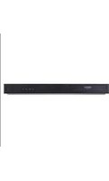
- SAFETY INFORMATION
- CAUTION
- REGULATORY INFORMATION: FCC PART
- CE
- DISPOSAL OF YOUR OLD APPLIANCE
- IMPORTANT SAFETY INSTRUCTIONS
- PLEASE FOLLOW THE DIRECTIONS TO SAFELY USE THE PRODUCT
- WARNING
- CONTENTS
- PLEASE FOLLOW THE DIRECTIONS TO USE THE PRODUCT SAFELY
- BEFORE USE
- FUNCTIONAL DESCRIPTION
- WEB VIEWER
- APPLE IPHONE/IPOD
- REFERENCE
- SERVICE
- PRODUCT CHARACTERISTICS
- COMPONENTS
- FRONT SIDE
- LE6016N MODEL
- REAR SIDE
- REMOTE CONTROLLER
- HOW TO SET THE ID OF THE REMOTE CONTROLLER
- CONNECTION AND INITIAL SETTING
- RS-485 CONNECTION
- CONTROL PORT (OUTPUT) CONNECTION
- SENSOR (INPUT) CONNECTION
- NOTE
- ABOUT INTERNAL HARD DISK
- HARD DISK INSTALLATION OR REPLACEMENT
- HARD DISK INSTALLATION
- HARD DISK REPLACEMENT
- CONNECTING E-SATA HDD
- RECOMMENDED LIST OF HARD DISK
- DATABASE RECOVERY OF THE HDD
- ARRANGEMENT OF THE DATABASE ON THE HDD
- CHECK THE HDD PROBLEM
- OPERATION
- START UP
- [USER]
- [PASSWORD]
- SHUTDOWN
- MONITOR SCREEN
- SYSTEM SETTING
- [OVERVIEW]
- [DATE/TIME]
- [INITIALIZE]
- [CONTROLLER]
- CAMERA
- [CHANNEL]
- [RECORDING]
- [SCHEDULE]
- [COLOR]
- [PTZ]
- EVENT
- [SENSOR]
- [MOTION DETECTION]
- [VIDEO LOSS]
- [E-MAIL]
- NETWORK
- [TCP/IP]
- FOR DYNAMIC IP OR PPPOE
- FOR STATIC IP
- [STREAMING]
- [DDNS]
- [CMS]
- [EVENT FILTER]
- INFORMATION
- [SETTING UPDATE]
- PTZ CONTROL
- SEARCH (PLAYBACK) & BACKUP
- TIME SEARCH
- SEARCH METHOD
- EVENT SEARCH
- BOOKMARK
- ADD
- SEARCH
- DELETE
- BACKUP
- HOW TO CANCEL BACKUP
- MEDIA ERASE
- INSTALLATION
- WEB VIEWER INSTALLATION
- WEB VIEWER SEARCH WINDOW
- REAL-TIME MONITORING
- CHECK BEFORE REQUESTING FOR SERVICE
- RECOMMENDED DEVICE TO USE
- INITIAL SETTING LIST FOR FACTORY DEFAULT
- PRODUCT SPECIFICATION
- LG
Brand : LG
Model : LE6016N-NH
Category : Video recorder