MKHI 804FH ED BK - Cooker Master Kitchen - Free user manual and instructions
Find the device manual for free MKHI 804FH ED BK Master Kitchen in PDF.


| Product Type | Induction Hob with Integrated Hood |
| Brand | Master Kitchen |
| Model | MKHI 804FH ED BK |
| Number of Cooking Zones | 4 (including 1 flexible zone) |
| Supply Voltage | 220-240V~ / 380-415V 3N~ 50Hz or 60Hz |
| Installed Electric Power | 7400 W |
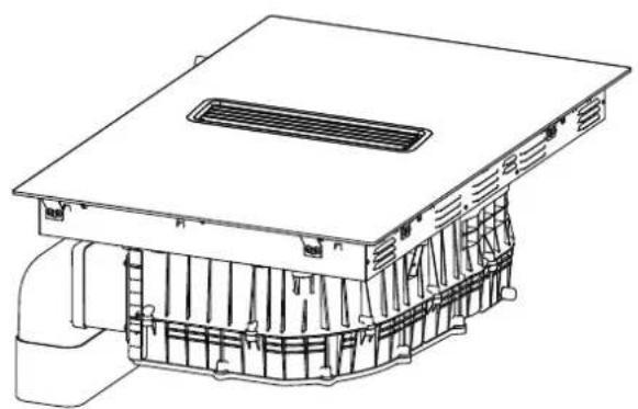
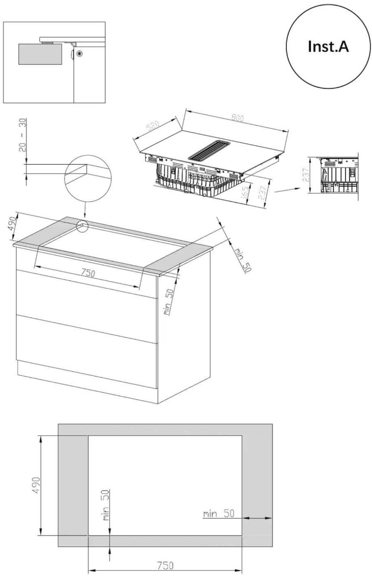
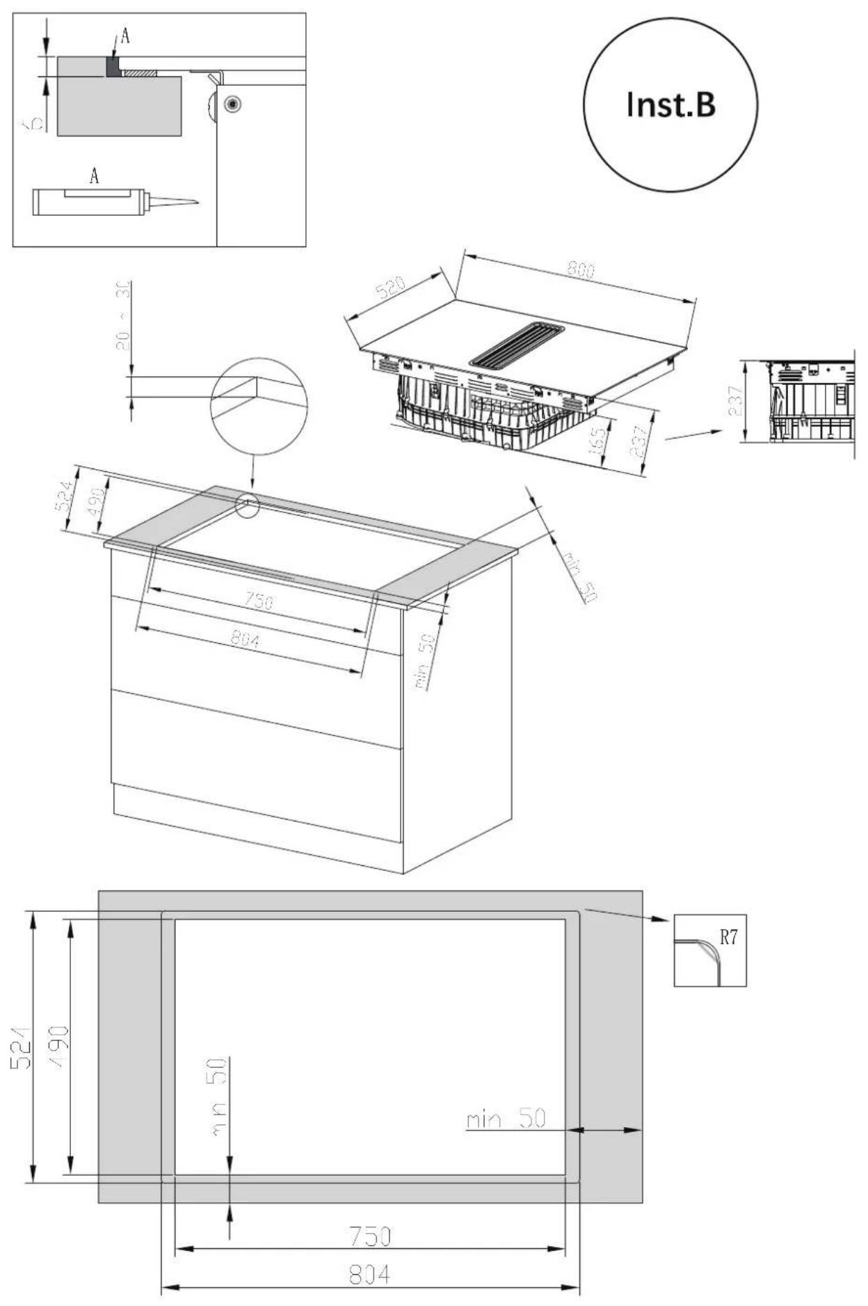
| Product Dimensions (DxWxH) | 800 x 520 x 237 mm |
| Building-in Dimensions (AxB) | 750 x 490 mm |
| Energy Efficiency Class (Hood) | A |
| Fluid Dynamic Efficiency Class | B |
| Grease Filtering Efficiency Class | C |
| Annual Energy Consumption (Hood) | 30.8 kWh/a |
| Maximum Air Flow (Boost, Ducted) | 629 m³/h |
| Maximum Air Flow (Boost, Recirculated) | 530 m³/h |
| Noise Level (Boost, Ducted) | 72 dB |
| Noise Level (Boost, Recirculated) | 74 dB |
| Motor Type | BLDC |
| Control Type | Touch controls |
| Cooktop Surface | Ceramic glass |
| Safety Features | Child lock, automatic shut-off, pan detection, hot surface indicator |
| Cleaning and Maintenance | Grease filters cleanable in dishwasher or manually; replace odor filter regularly |
Frequently Asked Questions - MKHI 804FH ED BK Master Kitchen
User questions about MKHI 804FH ED BK Master Kitchen
0 question about this device. Answer the ones you know or ask your own.
Ask a new question about this device
Download the instructions for your Cooker in PDF format for free! Find your manual MKHI 804FH ED BK - Master Kitchen and take your electronic device back in hand. On this page are published all the documents necessary for the use of your device. MKHI 804FH ED BK by Master Kitchen.
USER MANUAL MKHI 804FH ED BK Master Kitchen
natural_image
Simple line icon showing a house with a crossed hammer and sickle symbol inside, no text or numbers present.natural_image
Symbolic icon of a crossed hammer and sickle inside a house outline, representing anti-smoking or insecurity (no text present)natural_image
Technical line drawing of a mechanical housing or enclosure component with internal structural ribs and ventilation slots (no text or symbols)
natural_image
Two stylized human figures with a checkmark symbol between them, no text or labels present.natural_image
Technical line drawing of a mechanical component with internal channels and mounting brackets (no text or symbols)natural_image
Simple rectangular outline with dashed border (no text or symbols)1 × , B
7×M5

4 × ST3.5
natural_image
Technical line drawing of a 3D rectangular frame with curved top and base, labeled '1×' (no text or symbols on the diagram itself)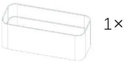
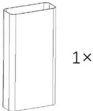
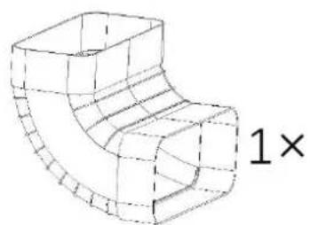
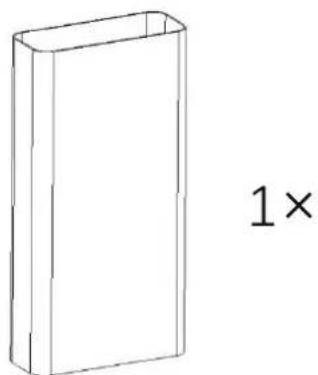
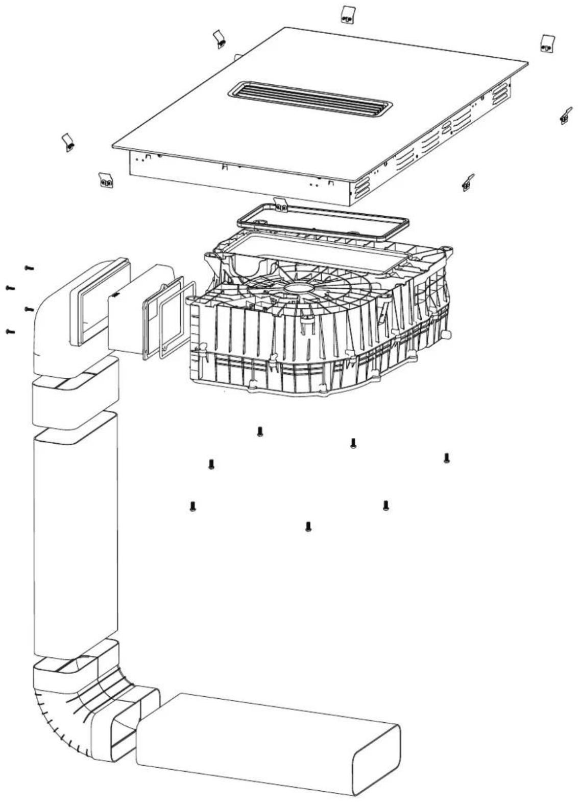
natural_image
Exploded view diagram of a computer motherboard showing internal components like CPU socket, fan, and drive unit (no text or labels)natural_image
Exploded view diagram of a mechanical assembly showing internal components and structural details (no text or labels)natural_image
Pure diagram of a mechanical or fluid system with curved arrows indicating direction, no text or symbols present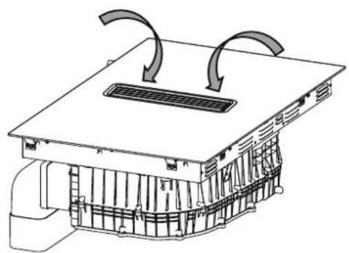
natural_image
Technical line drawing of a mechanical ventilation system with airflow arrows (no text or symbols)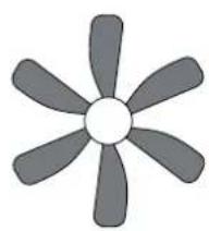
natural_image
Simple gray fan-shaped diagram with six blades, no text or symbols presentnatural_image
Simple line drawing of a rectangular frame with a horizontal line inside, no text or symbols present.!
natural_image
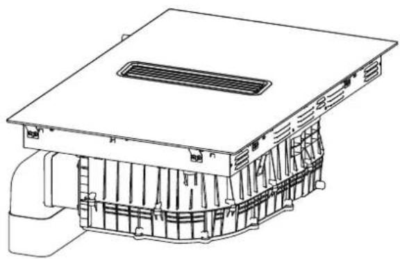
Technical line drawing of a mechanical housing or enclosure with internal components and ventilation slots (no text or symbols)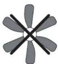
natural_image
Abstract geometric diagram of a six-blade fan with intersecting blades (no text or symbols)!
natural_image
Line drawing of a multi-compartment drawer with arrows indicating folding or reordering process (no text or symbols)OK!
natural_image
Line drawing of a simple rectangular sink or basin with four legs, no text or symbols present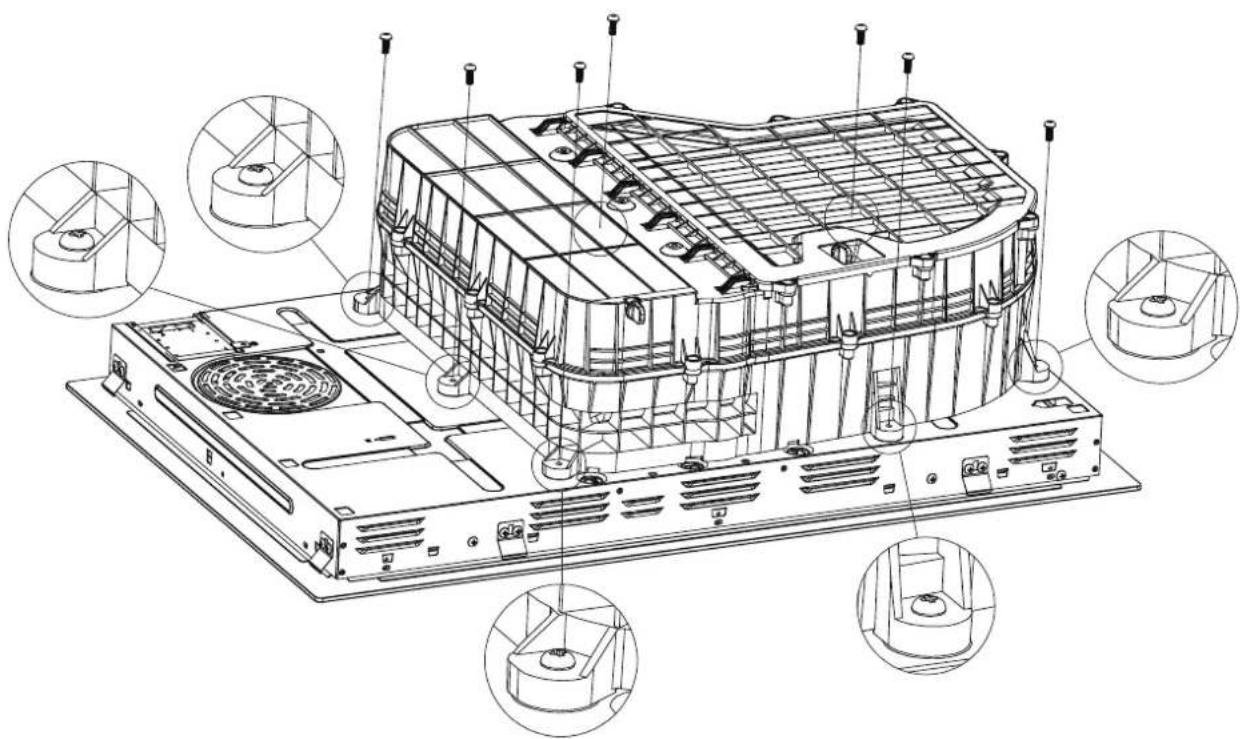
natural_image
Technical line drawing of an electronic device chassis with multiple views and mounting brackets (no text or symbols)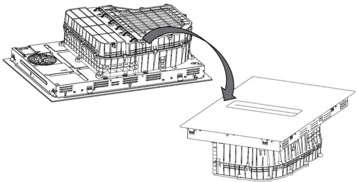
natural_image
Technical line drawing of an electronic device chassis with a magnified view showing internal components (no text or symbols)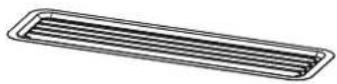
1x
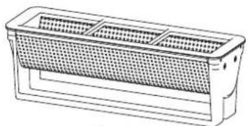
natural_image
Line drawing of a rectangular container with a mesh pattern on the front face (no text or symbols)1x
②
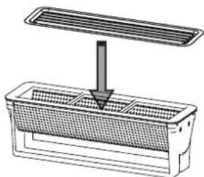
natural_image
Diagram of a ventilation system with a fan and vent, showing airflow direction (no text or labels)①
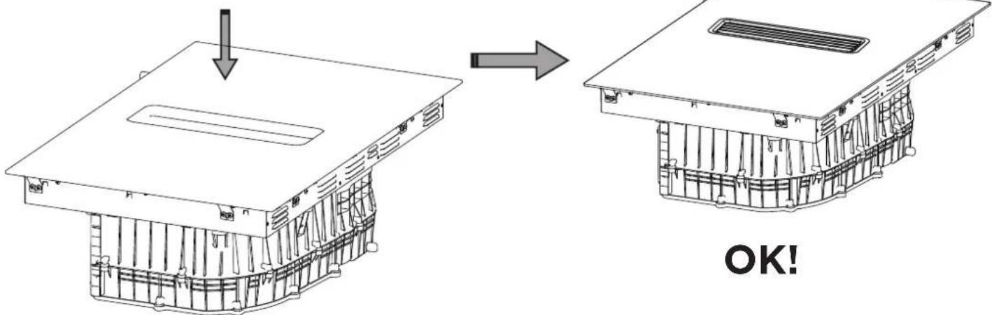
OK!
natural_image
Gray 3D mechanical component with a left-pointing arrow (no text or symbols)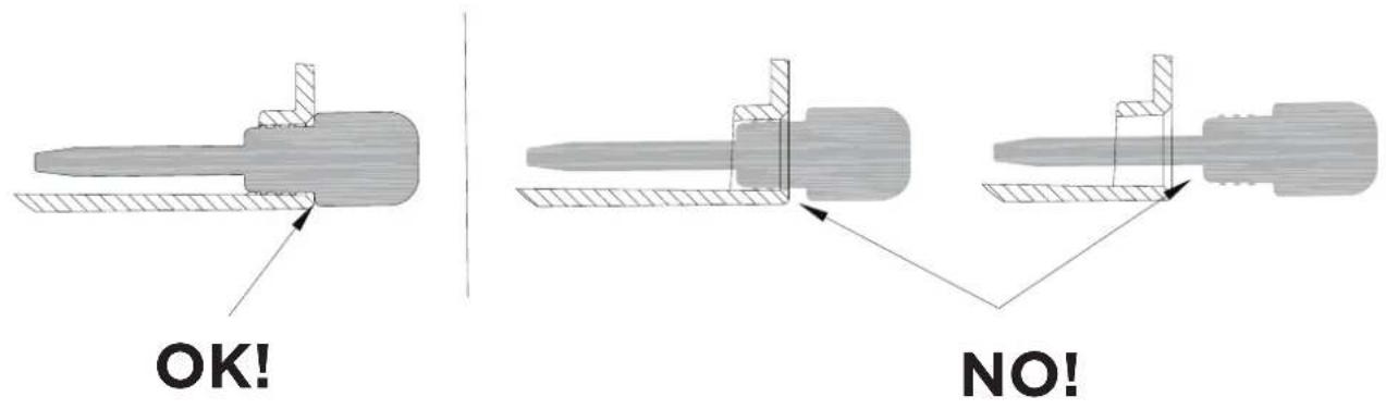
natural_image
Simple line icon of a house with arrows indicating direction and a cross symbol inside (no text or numbers)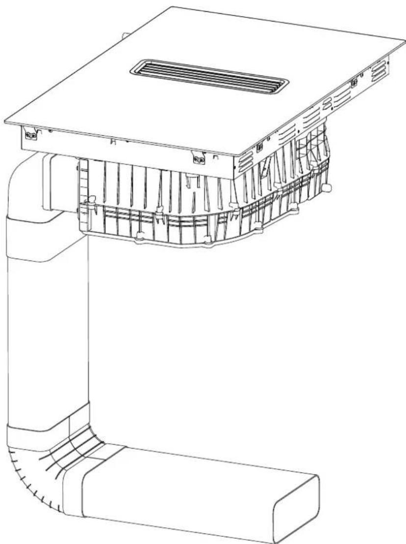
natural_image
Technical line drawing of a mechanical device with internal components and mounting bracket (no text or symbols)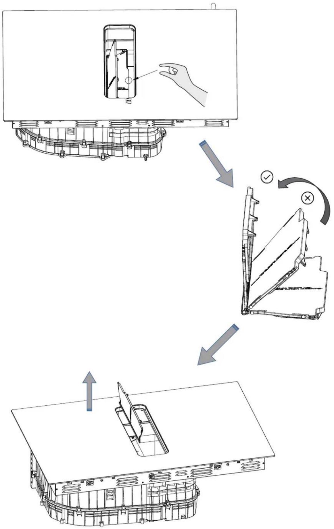
flowchart
graph TD
    A["Device with central component"] --> B["Inserted part"]
    B --> C["Assembly step 1"]
    C --> D["Assembly step 2"]
    D --> E["Final packaging"]
natural_image
Technical line drawing of a mechanical assembly with internal components and mounting brackets (no text or symbols)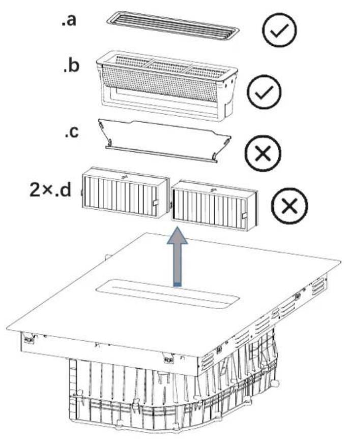
OK!
natural_image
Symbolic icon of a shield with crossed cross and lightning bolts, no text or numbers present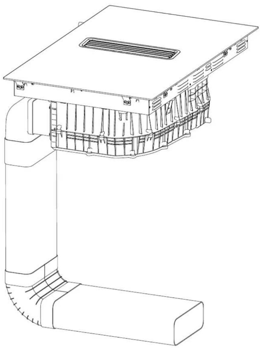
natural_image
Technical line drawing of a mechanical component with internal channels and mounting brackets (no text or symbols)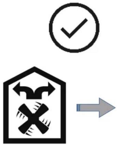
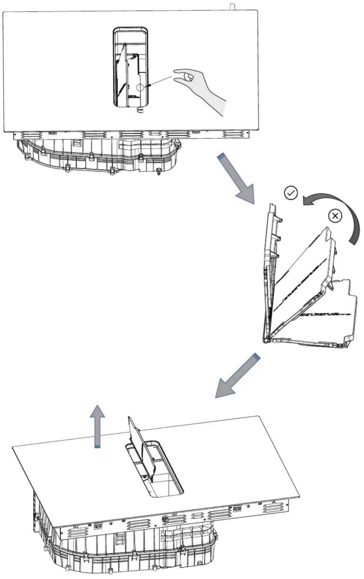
flowchart
graph TD
    A["Device with Component"] --> B["Inserted into a case"]
    B --> C["Revised into a case with a checkmark and cross symbol"]
    C --> D["Final packaging with a blade and cover"]
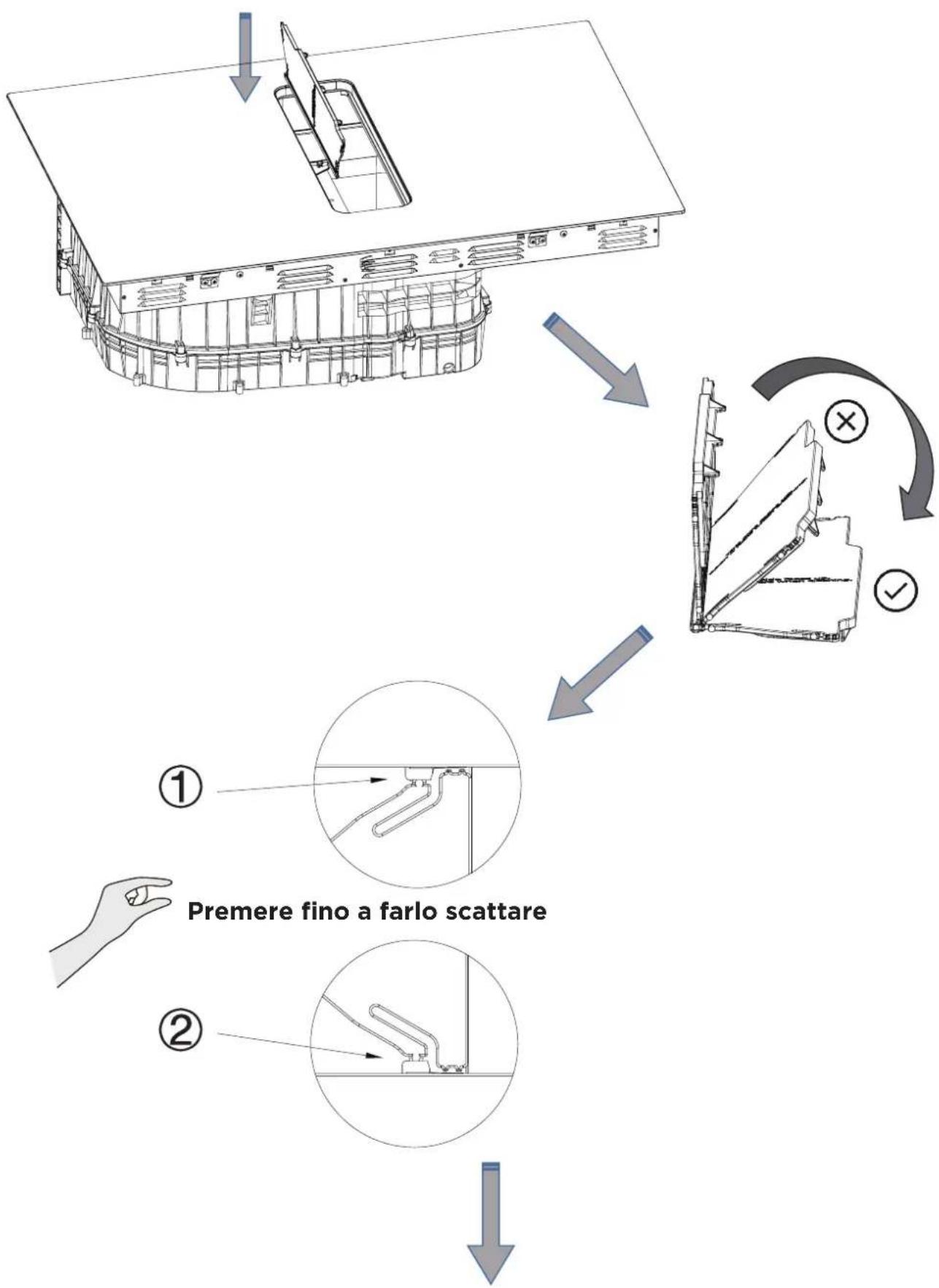
flowchart
graph TD
    A["Assembly Module"] --> B["Assembly Facility"]
    B --> C["Assembly Panel"]
    C --> D["Assembly Window"]
    D --> E["Assembly Checkmark"]
    style A fill:#f9f,stroke:#333
    style B fill:#ccf,stroke:#333
    style C fill:#cfc,stroke:#333
    style D fill:#fcc,stroke:#333
    style E fill:#ffc,stroke:#333
    note1["Premere fino a farlo scattare"] --> A
    note2["Bottom Left: ①"] --> A
    note3["Bottom Right: ②"] --> A
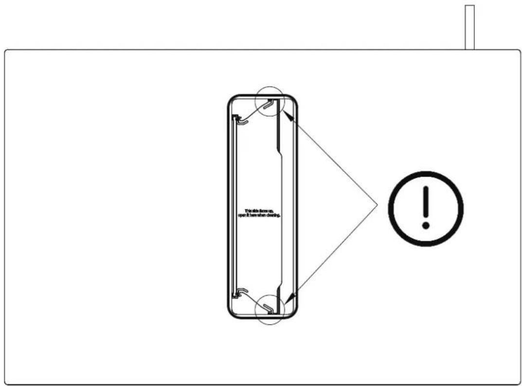
220-240V 1N-
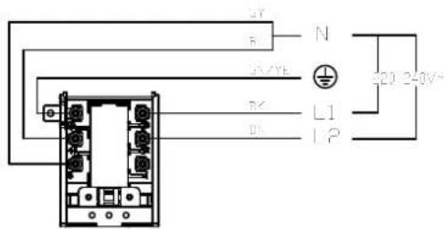
220-240V-/380-415V 3N-

natural_image
Simple line drawing of a cooking pot with a coiled tube (no text or symbols)natural_image
Three identical cooking pots with crossed-out kitchen panes, no text or symbols presentnatural_image
Two cooking pots with crossed arrows indicating heating or resistance, one above and one below (no text or symbols)Modalità d'uso
natural_image
Line drawing of a cooking pot on a stand (no text or symbols)natural_image
3D rendering of a mechanical component with a rectangular housing and a slatted panel, placed on a flat base (no text or symbols visible)natural_image
3D diagram of a mechanical assembly with a block and a base, showing upward force arrows (no text or symbols)natural_image
3D diagram of a mechanical assembly with a block and support structure (no text or symbols)natural_image
3D rendering of a mechanical component with a rectangular housing and a slatted plate, no visible text or symbolsnatural_image
3D rendering of a mechanical component with a rectangular housing and a slatted plate, no visible text or symbolsnatural_image
Symbol of a trash bin crossed out by two crossed lines, with no text or labels present.natural_image
Recycling symbol with four arrows forming a triangle (no text or labels)THANK YOU LETTER
Thank you for choosing MASTER KITCHEN! Before using your new MASTER KITCH product, please read this manual thoroughly to ensure that you know how to operate the features and functions that your new appliance offers in a safe way.
CONTENTS
THANK YOU LETTER 01
SAFETY INSTRUCTIONS 02
SPECIFICATIONS 10
PRODUCT OVERVIEW 12
QUICK START GUIDE 15
PRODUCT INSTALLATION 17
OPERATION INSTRUCTIONS 55
CLEANING AND MAINTENANCE 62
TROUBLESHOOTING 67
DISPOSAL AND RECYCLING 71
SAFETY INSTRUCTIONS
Intended Use
The following safety guidelines are intended to prevent unforeseen risks or damage from unsafe or incorrect operation of the appliance. Please check the packaging and appliance on arrival to make sure everything is intact to ensure safe operation. If you find any damage, please contact the retailer or dealer. Please note modifications or alterations to the appliance are not allowed for your safety concern. Unintended use may cause hazards and loss of warranty claims.
Explanation of Symbols
 | DangerThis symbol indicates that there are dangers to the life and health of persons due to extremely flammable gas. |
 | Warning of electrical voltageThis symbol indicates that there is a danger to life and health of persons due to voltage. |
 | WarningThe signal word indicates a hazard with a medium level of risk which, if not avoided, may result in death or serious injury. |
 | CautionThe signal word indicates a hazard with a low degree of risk which, if not avoided, may result in minor or moderate injury. |
 | AttentionThe signal word indicates important information (e.g. damage to property), but not danger. |
 | Observe instructionsThis symbol indicates that a service technician should only operate and maintain this appliance in accordance with the operating instructions. |
Read these operating instructions carefully and attentively before using/commissioning the unit and keep them in the immediate vicinity of the installation site or unit for later use!
Safety Warnings
Your safety is important to us. Please read this information before using your cooktop. Please strictly observe the instructions in this manual. No liability will be assumed for any problems, damage or fires caused by failure to comply with the instructions in this manual. The device is intended for domestic use only, to cook food and extract the fumes generated by cooking. No other use is allowed (e.g. heating rooms). The manufacturer declines any liability for inappropriate use or incorrect setting of the controls.
The product may have different aesthetic features with respect to the illustrations in this handbook, however the operating, maintenance and installation instructions remain the same.
This manual must be stored for future consultation at any time. If sold, transferred or moved, it must remain with the product.
Installation
Electrical Shock Hazard
- Disconnect the appliance from the mains electricity supply before carrying out any work or maintenance on it.
- Connection to a good earth wiring system is essential and mandatory.
- Alterations to the domestic wiring system must only be made by a qualified electrician.
- Failure to follow this advice may result in electrical shock or death.
- -Installation or maintenance must be performed by a qualified technician, in compliance with the manufacturer's instructions and with local safety regulations. Do not repair or replace any part of the device unless specifically stated in the operating manual.
- Earthing the device is compulsory.
- The power cable must be long enough, to allow the device, built-in to the cabinet, to be connected to the electrical network.
- In order to ensure the installation complies with current safety standards, a regular omnipolar switch is required that assures the complete disconnection of the mains under category III over-voltage conditions, in accordance with the installation rules.
- Do not use multiple sockets or extension cords. -Once installation is complete, the electrical components must no longer be accessible by the user.
- Before connecting the device to the electrical network: check the data plate (on the bottom of the device) to ensure that the voltage and power correspond to the network values and that the connection socket is suitable. If in doubt, consult a qualified electrician.
Cut Hazard
• Take care - panel edges are sharp.
- Failure to use caution could result in injury or cuts.
Important Safety Instructions
- Read these instructions carefully before installing or using this appliance.
- No combustible material or products should be placed on this appliance at any time.
- Please make this information available to the person responsible for installing the appliance as it could reduce your installation costs.
- In order to avoid a hazard, this appliance must be installed according to these instructions for installation.
- This appliance is to be properly installed and earthed only by a suitably qualified person.
- This appliance should be connected to a circuit which incorporates an isolating switch providing full disconnection from the power supply.
- Failure to install the appliance correctly could invalidate any warranty or liability claims.
- This appliance can be used by children aged from 8 years and above and persons with reduced physical, sensory or mental capabilities or lack of experience and knowledge if they have been given supervision or instruction concerning use of the appliance in a safe way and understand the hazards involved.
- Children shall not play with the appliance. Cleaning and user maintenance shall not be made by children without supervision.
- If the supply cord is damaged, it must be replaced by the manufacturer, its service agent or similarly qualified persons in order to avoid a hazard.
- Warning: If the surface is cracked, switch off the appliance to avoid the possibility of electric shock, for hob surfaces of glass-ceramic or similar material which protect live parts
- Metallic objects such as knives, forks, spoons and lids should not be placed on the hob surface since they can get hot
- A steam cleaner is not to be used.
- Do not use a steam cleaner to clean your cooktop.
- The appliance is not intended to be operated by means of an external timer or separate remote-control system.
- WARNING: Danger of fire: do not store items on the cooking surfaces.
- The cooking process has to be supervised. A short term cooking process has to be supervised continuously.
- WARNING: Unattended cooking on a hob with fat or oil can be dangerous and may result in fire. NEVER try to extinguish a fire with water, but switch off the appliance and then cover flame e.g. with a lid or a fire blanket.
- After use, switch off the hob from its control device and do not rely on the pot detector.
- Avoid spills; when boiling or heating liquids, lower the heat supply.
- Do not leave the heating elements on with pots and pans empty or without containers.
- Once cooking is complete, turn off the relative zone.
- Never use aluminium foil to cook with, and never directly place products packaged with aluminium on top of the cooking surface. The aluminium would melt and irreparably damage your device.
- Never heat a tin or a tin can containing foods without first opening it: it might explode!
Operation And Maintenance
Electrical Shock Hazard
- Do not cook on a broken or cracked cooktop. If the cooktop surface should break or crack, switch the appliance off immediately at the mains power supply (wall switch) and contact a qualified technician.
- Switch the cooktop off at the wall before cleaning or maintenance.
- Failure to follow this advice may result in electrical shock or death.
Health Hazard
- This appliance complies with electromagnetic safety standards.
- However, persons with cardiac pacemakers or other electrical implants (such as insulin pumps) must consult with their doctor or implant manufacturer before using this appliance to make sure that their implants will not be affected by the electromagnetic field.
- Failure to follow this advice may result in death.
Hot Surface Hazard
- During use, accessible parts of this appliance will become hot enough to cause burns.
- Do not let your body, clothing or any item other than suitable cookware contact the Induction glass until the surface is cool.
- Keep children away.
- Handles of saucepans may be hot to touch. Check saucepan handles do not overhang other cooking zones that are on. Keep handles out of reach of children.
- Failure to follow this advice could result in burns and scalds.
Cut Hazard
- The razor-sharp blade of a cooktop scraper is exposed when the safety cover is retracted. Use with extreme care and always store safely and out of reach of children.
- Failure to use caution could result in injury or cuts.
Important Safety Instructions
- Never leave the appliance unattended when in use. Boilover causes smoking and greasy spillovers that may ignite.
- Never use your appliance as a work or storage surface.
- Never leave any objects or utensils on the appliance.
- Do not place or leave any magnetisable objects (e.g. credit cards, memory cards) or electronic devices (e.g. computers, MP3 players) near the appliance, as they may be affected by its electromagnetic field.
- Never use your appliance for warming or heating the room.
- After use, always turn off the cooking zones and the cooktop as described in this manual (i.e. by using the touch controls). Do not rely on the pan detection feature to turn off the cooking zones when you remove the pans.
- Do not allow children to play with the appliance or sit, stand, or climb on it.
- Do not store items of interest to children in cabinets above the appliance. Children climbing on the cooktop could be seriously injured.
- Do not leave children alone or unattended in the area where the appliance is in use.
- Children or persons with a disability which limits their ability to use the appliance should have a responsible and competent person to instruct them in its use. The instructor should be satisfied that they can use the appliance without danger to themselves or their surroundings.
- Do not repair or replace any part of the appliance unless specifically recommended in the manual. All other servicing should be done by a qualified technician.
- Do not place or drop heavy objects on your cooktop.
- Do not stand on your cooktop.
- Do not use pans with jagged edges or drag pans across the Induction glass surface as this can scratch the glass.
- Do not use scourers or any other harsh abrasive cleaning agents to clean your cooktop, as these can scratch the Induction glass.
- This appliance is intended to be used in household and similar applications such as: -staff kitchen areas in shops, offices and other working environments; -farm houses; -by clients in hotels, motels and other residential type environments; -bed and breakfast type environments.
- WARNING: The appliance and its accessible parts become hot during use.
- Care should be taken to avoid touching heating elements.
- Children less than 8 years of age shall be kept away unless continuously supervised.
- The room must be properly ventilated when the cooker hood is used at the same time as other combustion devices, gas or otherwise.
- The hood must be regularly cleaned both internally and externally (AT LEAST ONCE PER MONTH), in strict accordance with the maintenance instructions.
- Failure to follow the rules for hood cleaning and filter replacement and cleaning shall result in a fire hazard.
- It is strictly prohibited to flame food. The use of an open flame may damage the filters and cause a fire hazard; it must therefore be avoided under all circumstances. Extra care must be taken when frying to prevent the oil from overheating and catching fire.
- CAUTION: When the hob is on, the accessible parts of the hood may become hot.
- In regards to the technical and safety measures that must be adopted for fume extraction, regulations issued by local authorities must be strictly followed.
- The extracted air must not be conveyed through the same ducts used to extract the fumes generated by gas combustion or other types of combustion devices. Never use the hood unless the grill has been correctly assembled!
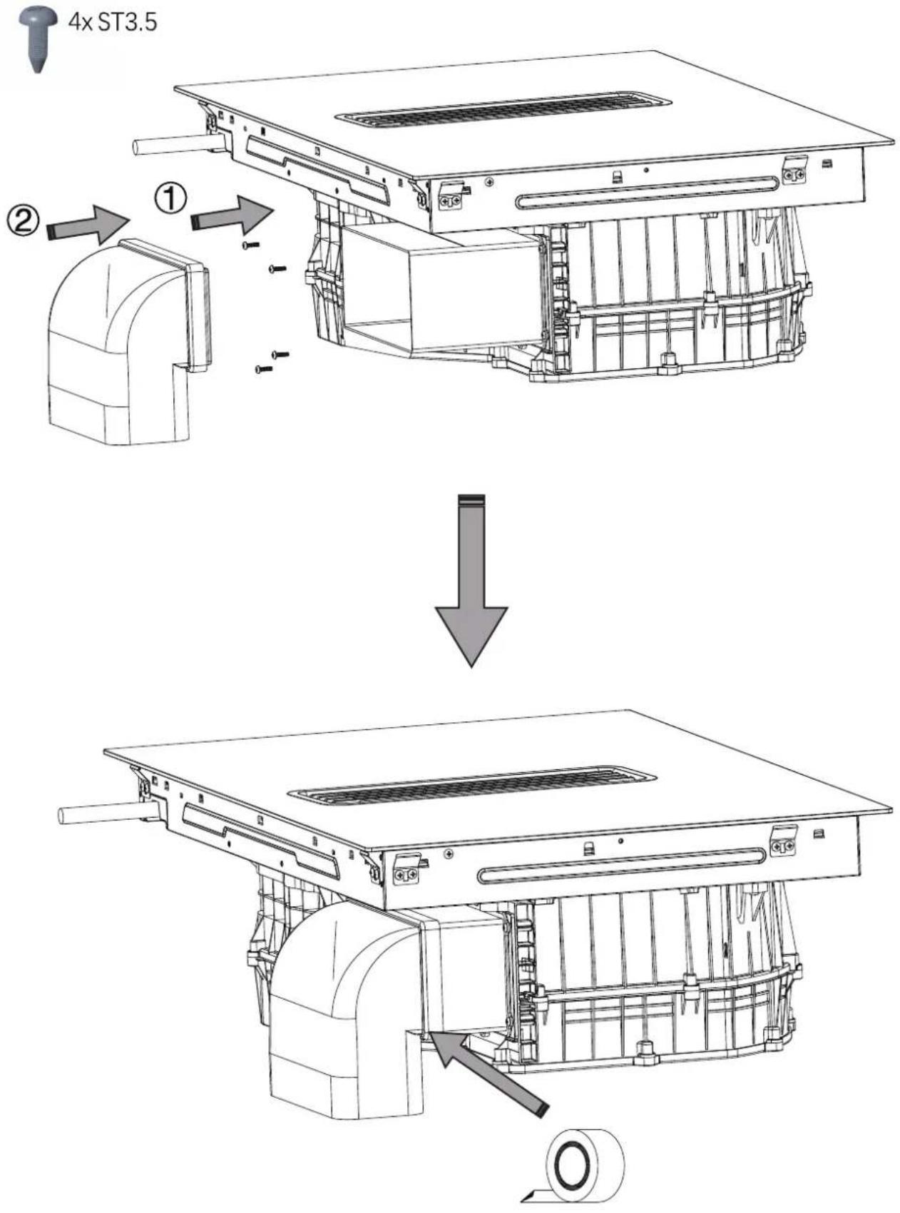
- Use only the fastening screws supplied with the product for its installation, or if not supplied, purchase the correct type of screws. Use screws with the right length, as indicated in the installation guide.
- When the cooker hood is used together with other devices powered with non-electrical energy, the negative pressure of the room must not exceed 4 Pa (4 x 10⁻⁵ bar). This can be achieved whenever the air needed for combustion is able to enter through openings that cannot be sealed, for example in doors, windows, incoming/exhaust air wall boxes or byother technical means. An incoming/ex-haust air wall box alone does not ensure compliance with the limit.
- Recommendations for correct use in order to reduce the impact on the environment: When starting to cook, turn on the hood at minimum speed and leave it on for a few minutes even after cooking is complete. Increase the speed only if there is a large amount of fumes and steam, using the Booster function only in extreme cases. To keep the odour reduction system running efficiently, replace the carbon filter/s when necessary.
- To ensure the high performance of the grease filter, clean it when necessary. To improve efficiency and minimise noise, use the maximum ducting diameter indicated in this manual.
• Leaving fat or oil cooking on an unattended hob can be dangerous and may lead to fires.
- Never leave hot oil or fat unattended.
- Never operate the appliance without grease filter.
- Never work with naked flames close to the appliance (e.g. flambéing) around the grease filters.
- Do not install the appliance near a solid fuel heating appliance (e.g. wood- or coal-burning) unless the heating appliance hasa sealed, non-removable cover. There must be no flying sparks.
- Allow the appliance to cool down beforecleaning.
- If hot liquids penetrate the appliance, only remove the grease filter or the overflow container once the appliance has cooled down.
- There is a slight odor when unpacking, and it will soon disappear.
- WARNING: Use only hob guards designed by the manufacturer of the cooking appliance or indicated by the manufacturer of the appliance in the instructions[RY1] for use as suitable or hob guardsincorporated in the appliance. The use of inappropriate guards can cause accidents.
- Range hoods and other cooking fumeextractors may adversely affect the safe operation of appliances burning gas orother fuels (including those in other rooms) due to back flow of combustiongases. These gases can potentially result in carbon monoxide poisoning. Afterinstallation of a range hood or other cooking fume extractor, the operation offlued gas appliances should be tested by a competent person to ensure that backflow of combustion gases does not occur.
- there is a fire risk if cleaning is not carried out in accordance with the instructions
- CAUTION: Accessible parts may become hot when used with cooking appliances.
- regulations concerning the discharge of air have to be fulfilled.
- CAUTION: This appliance is not intended to be used with gas hobs.
Congratulations on the purchase of your new Induction Hob.
We recommend that you spend some time to read this Instruction / Installation Manual in order to fully understand how to install correctly and operate it.
For installation, please read the installation section.
Read all the safety instructions carefully before use and keep this Instruction / Installation Manual for future reference.
SPECIFICATIONS
| Cooking Hob | MKHI 804FH ED BK |
| Cooking Zones | 4 Zones |
| Supply Voltage | 220-240V~ 380-415V 3N~ 50Hz or 60Hz |
| Installed Electric Power | 7400W |
| Product Size DxWxH(mm) | 800X520X237 |
| Building-in Dimensions AxB (mm) | 750X490 |
| Motor BLDC |
Energy labelling
| Manufacturer | MASTER KITCHEN | ||
| Model identification | MKHI 804FH ED BK | ||
| Symbol | Value Unit | ||
| Energy consumption | |||
| Annual energy consumption AEC | hood | 30.8 kWh/a | |
| Energy efficiency class | - A - | ||
| Energy efficiency index EEI | hood | 49.9 | - |
| Fluid dynamic efficiency FDE | hood | 26.4 | - |
| Fluid dynamic efficiency class | - | B | - |
| Lighting | |||
| Lighting efficiency LE | hood | N/A lux/W | |
| Lighting efficiency class - N/A - | |||
| Grease filtering | |||
| Grease filtering efficiency GFE | hood | 77.9 % | |
| Grease filtering efficiency class - C - | Symbol Value | Unit | |
| Air flow volume (ducted extraction) | |||
| Maximum air flow at lowest setting in normal use | -329 m^3/h | ||
| Maximum air flow at highest setting in normal use | -521 m^3/h | ||
| Maximum air flow at boost setting | -629 m^3/h | ||
| Noise(ducted extraction) | |||
| Airborne acoustical A-weighted sound power emissions at lowest setting | -57 dB | ||
| Airborne acoustical A-weighted sound power emissions at highest setting | -68 dB | ||
| Airborne acoustical A-weighted sound power emissions at boost setting | -72 dB | ||
| Power consumption | |||
| Power consumption in off mode | Po 0.42 W | ||
| Power consumption in standby mode | Ps N/A W | ||
| Air flow volume (recirculated extraction) | |||
| Maximum air flow at lowest setting in normal use | -355 m^3/h | ||
| Maximum air flow at highest setting in normal use | -473 m^3/h | ||
| Maximum air flow at boost setting | -530 m^3/h | ||
| Noise(recirculated extraction) | |||
| Airborne acoustical A-weighted sound power emissions at lowest setting | -64 | dB | |
| Airborne acoustical A-weighted sound power emissions at highest setting | - | 71 dB | |
| Airborne acoustical A-weighted sound power emissions at boost setting | -74 dB | ||
Weight and Dimensions are approximate. Because we continually strive to improve our products we may change specifications and designs without prior notice.
| the base diameter of induction cookware | ||
| Cooking zone | Minimum | Maximum |
| 1 & 2 & 3 & 4 | 140 | 200 |
| Flexing zone | 250 | 190*390 |
PRODUCT OVERVIEW
Top View
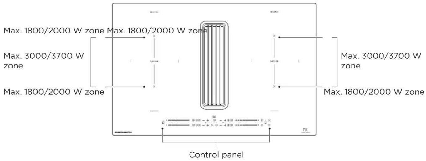
Control Panel
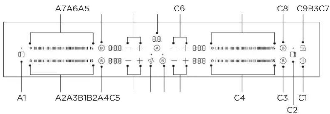
A1. Flexible Area control
A4. Time regulating controls
A7. Power regulating controls
B1. Hood regulating control
C1. ON/OFF control
C4. Power regulating controls
C7. Power regulating controls
A2. Power regulating controls
A5. Time regulating controls
B2. Boost
C2. Flexible Area control
C5. Time regulating controls
C8. Boost
A3. Boost
A6. Boost
B3. Hob and hood Auto
C3. Boost
C6. Time regulating controls
C9. Keylock control

NOTE
All the pictures in this manual are for explanation purpose only. Any discrepancy between the real object and the illustration in the drawing shall be subject to the real subject.
Working Theory
Induction cooking is a safe, advanced, efficient, and economical cooking technology. It works by electromagnetic vibrations generating heat directly in the pan, rather than indirectly through heating the glass surface. The glass becomes hot only because the pan eventually warms it up.
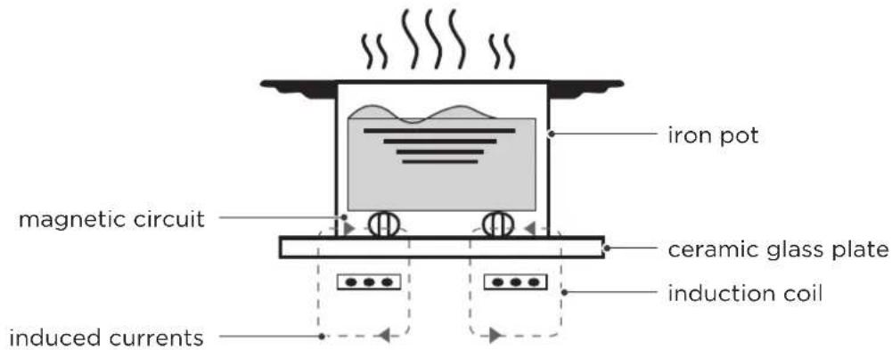
Operating Mode
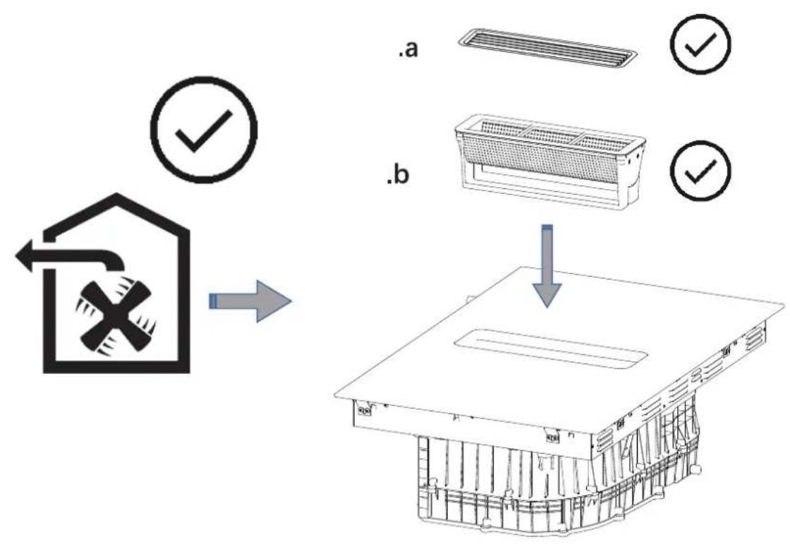
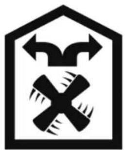
You can use your appliance in air extraction mode or circulating-air mode.
Air extraction mode
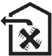
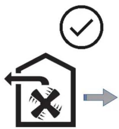
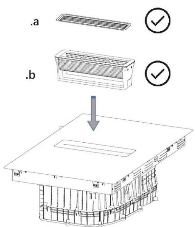
The air which is drawn in is cleaned by the grease filters and conveyed to the exterior by a pipe system.
natural_image
Simple line icon of a house with a crossed hammer and sickle symbol inside, no text or numbers present.The air must not be discharged into aflue that is used for exhausting fumesfrom appliances burning gas or otherfuels (not applicable to appliances thatonly discharge the air back into the room).
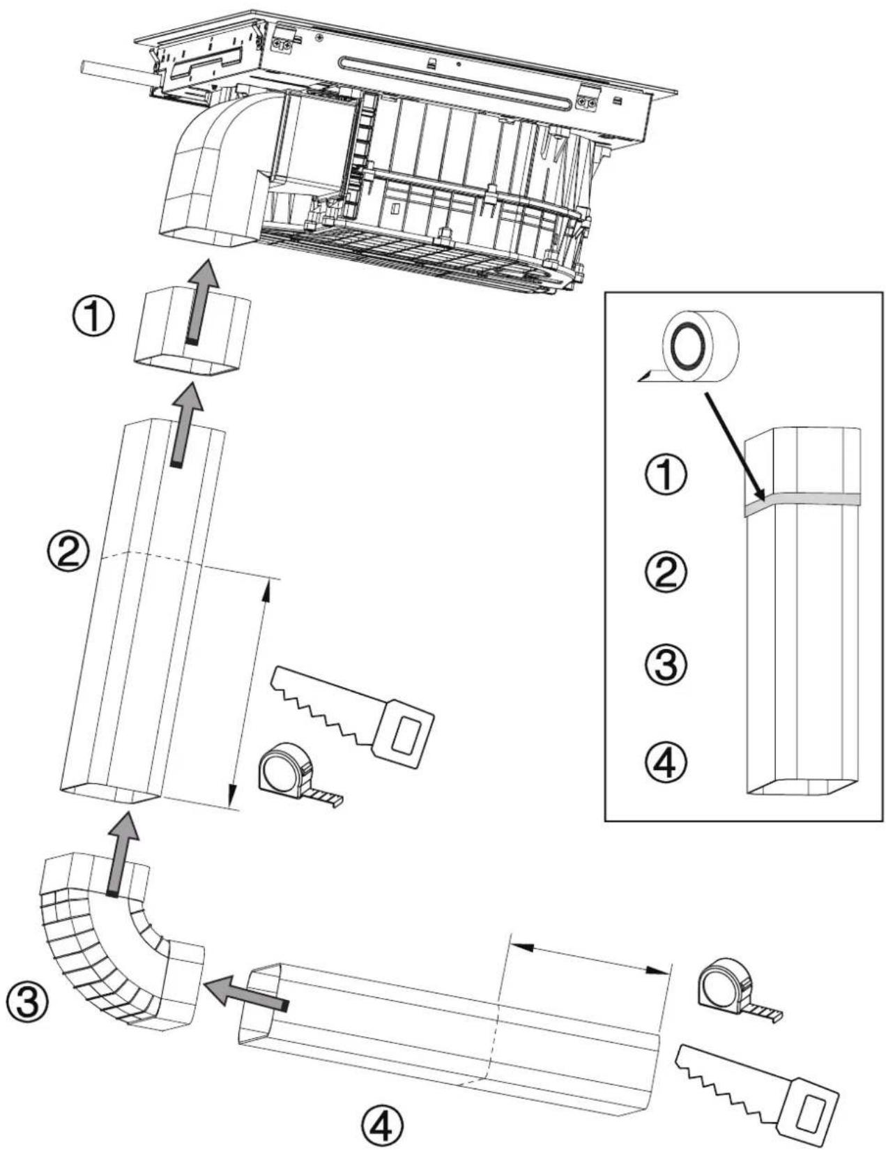
- If the exhaust air is to be conveyed into a non-functioning smoke or ex-haust gas flue, you must obtain the consent of the heating engineer responsible.
- If the exhaust air is conveyed through the external wall, a tele-scopic duct should be used.
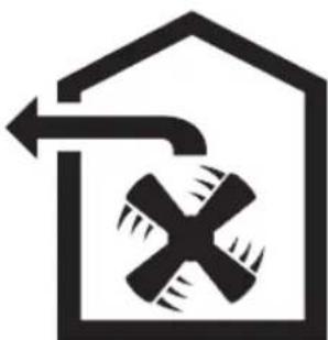
Air recirculation mode
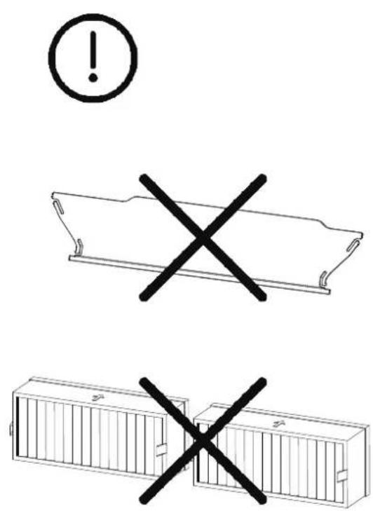
The air which is drawn in is cleaned by the grease fil-ters and an odour filter, and conveyed back into theroom.
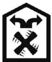
natural_image
Symbolic icon of a crossed hammer and sickle inside a house outline, with arrows indicating direction (no text or numbers present)To bind odours in circulating-air mode, you must install an odour filter. The dif-ferent options for operating the appli-ance in circulating-air mode can be found in our catalogue. Alternatively, ask your dealer.
Before Using Your New Induction Hob and Hood
- Read this guide, taking special note of the ‘Safety Warnings’ section.
- Remove any protective film that may still be on your Induction hob.
- Setting the operating mode.
The appliance is supplied with a preset Air extraction mode.
If you want to Air extraction mode to Circulating-air mode, You can follow the steps below:
1. Enter hood mode settings
State: Set Child Lock in power off state.
Entry conditions:
Press the Ⓐ key 3 seconds(+buzzer sound), and the LF digital tube will display "ou" or "In", using the lock key 🔍 to change the mode;
If it is in Air extraction mode now, and the LF digital tube will display "ou", use the power button ① to confirm and turn on the machine;
If it is in Circulating-air mode now, and the LF digital tube will display "In", use the power button ① to confirm and turn on the machine;
QUICK START GUIDE
Take care when frying as the oil and fat heat up very quickly, particularly if you're using PowerBoost. At extremely high temperatures oil and fat will ignite spontaneously and this presents a serious fire risk.
Cooking Tips
- When food comes to the boil, reduce the temperature setting.
- Using a lid will reduce cooking times and save energy by retaining the heat.
- Minimize the amount of liquid or fat to reduce cooking times.
- Start cooking on a high setting and reduce the setting when the food has heated through.
Simmering, cooking rice
- Simmering occurs below boiling point, at around 85^ , when bubbles are just rising occasionally to the surface of the cooking liquid. It is the key to delicious soups and tender stews because the flavours develop without overcooking the food. You should also cook egg-based and flour thickened sauces below boiling point.
- Some tasks, including cooking rice by the absorption method, may require a setting higher than the lowest setting to ensure the food is cooked properly in the time recommended.
Searing steak
To cook juicy flavorsome steaks:
- Stand the meat at room temperature for about 20 minutes before cooking.
- Heat up a heavy-based frying pan.
- Brush both sides of the steak with oil. Drizzle a small amount of oil into the hot pan and then lower the meat onto the hot pan.
- Turn the steak only once during cooking. The exact cooking time will depend on the thickness of the steak and how cooked you want it. Times may vary from about 2 - 8 minutes per side. Press the steak to gauge how cooked it is - the firmer it feels the more ‘well done’ it will be.
- Leave the steak to rest on a warm plate for a few minutes to allow it to relax and become tender before serving.
For Stir-frying
- Choose an induction compatible flat-based wok or a large frying pan.
- Have all the ingredients and equipment ready. Stir-frying should be quick. If cooking large quantities, cook the food in several smaller batches.
- Preheat the pan briefly and add two tablespoons of oil.
- Cook any meat first, put it aside and keep warm.
- Stir-fry the vegetables. When they are hot but still crisp, turn the cooking zone to a lower setting, return the meat to the pan and add your sauce.
- Stir the ingredients gently to make sure they are heated through.
- Serve immediately.
Detection Of Small Articles
When an unsuitable size or non-magnetic pan (e.g. aluminium), or some other small item (e.g. knife, fork, key) has been left on the hob, the hob automatically go on to standby in 1 minute. The fan will keep cooking down the induction hob for a further 1 minute.
Heat Settings
The settings below are guidelines only. The exact setting will depend on several factors, including your cookware and the amount you are cooking. Experiment with the induction hob to find the settings that best suit you.
| Heat setting Suitability | |
| 1 - 2 | ·delicate warming for small amounts of food·melting chocolate, butter, and foods that burn quickly·gentle simmering·slow warming |
| 3 - 5 | ·reheating·rapid simmering·cooking rice |
| 6 - 11 · pancakes | |
| 12 - 13 | ·fried·cooking pasta |
| 15/P | ·stir-frying·searing·bringing soup to the boil·boiling water |
PRODUCT INSTALLATION
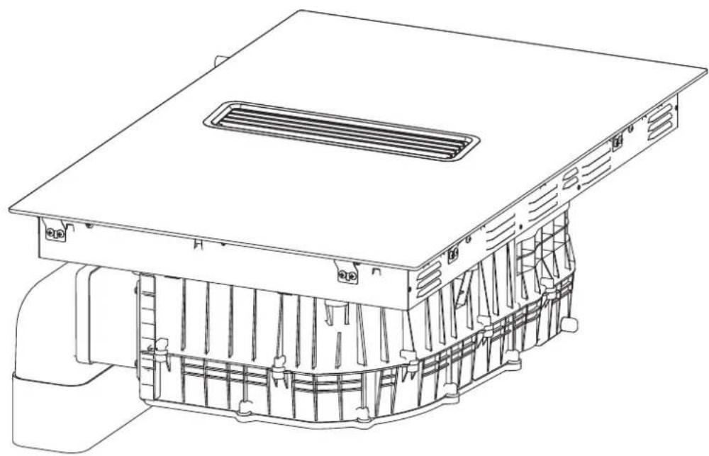
natural_image
Technical line drawing of a mechanical housing or enclosure component (no text or symbols)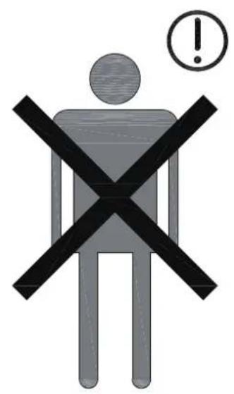
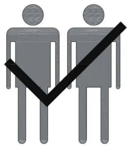
natural_image
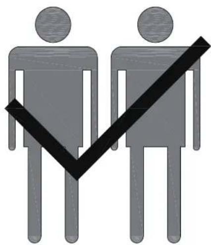
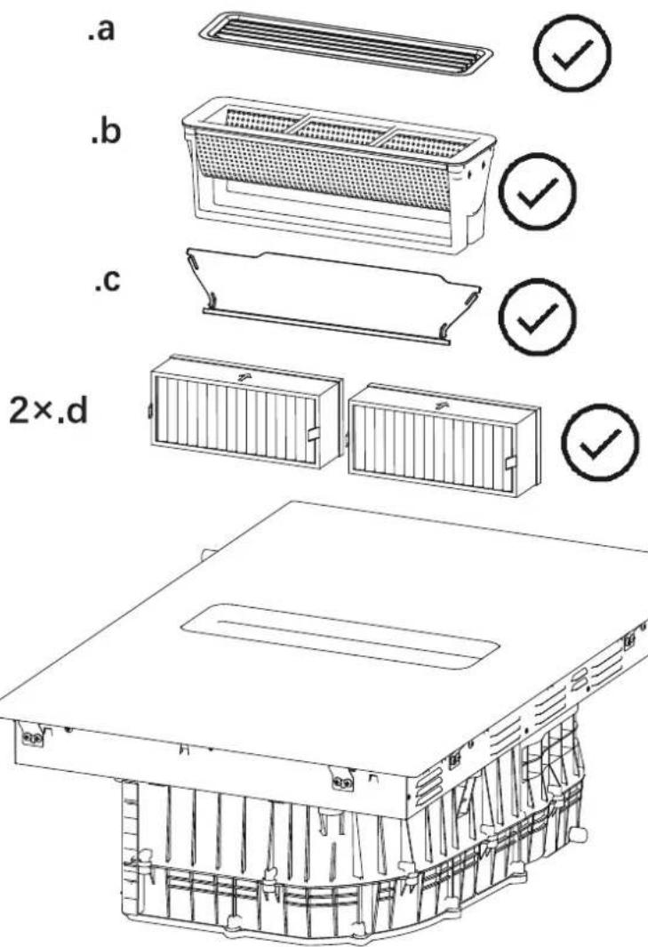
Two stylized human figures with a checkmark symbol between them, no text or labels presentComplete Equipment
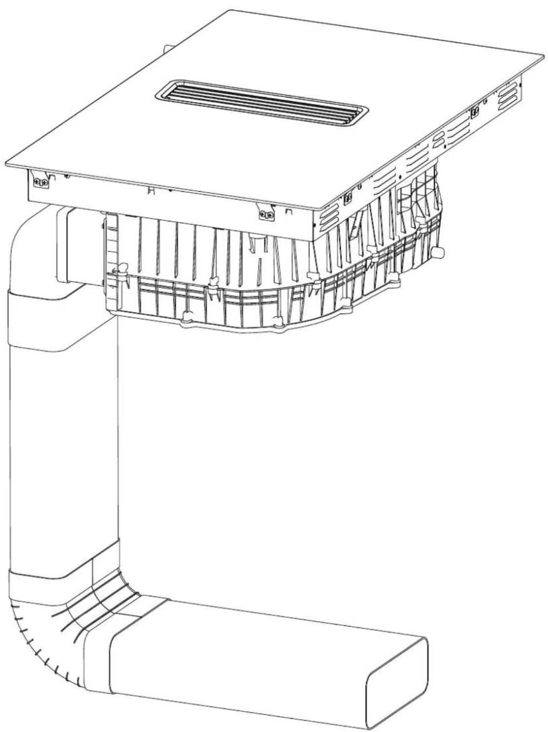
natural_image
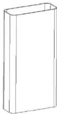
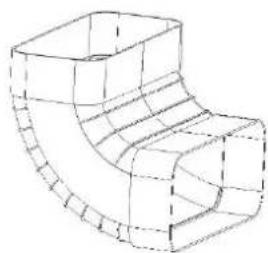
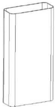
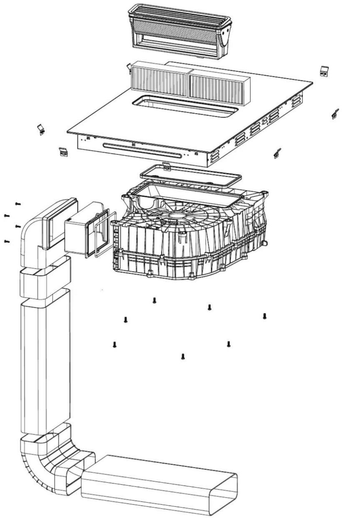
Technical line drawing of a mechanical component with internal channels and mounting brackets (no text or symbols)Installation Accessories, Outward Discharge
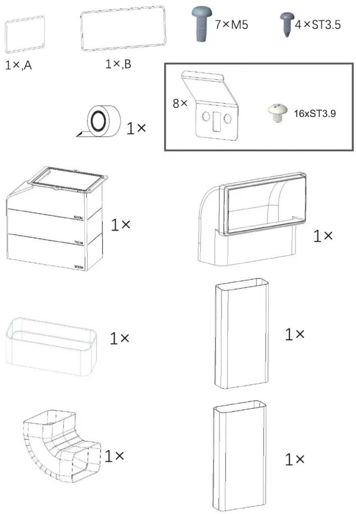
natural_image
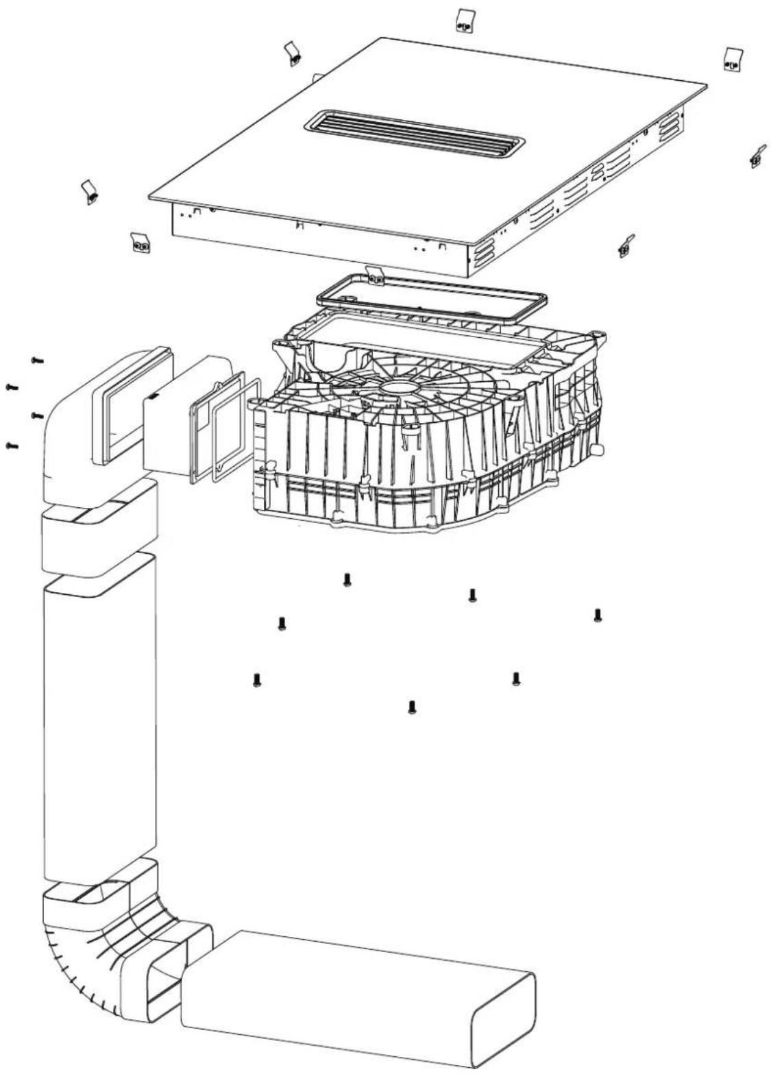
Exploded view diagram of a computer motherboard showing internal components like CPU socket, fan, and drive unit (no text or labels)Installation Accessories, Inward Discharge
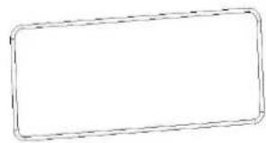
1 ×, A
natural_image
Simple rectangular outline with dashed border (no text or symbols)1 ×, B
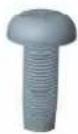
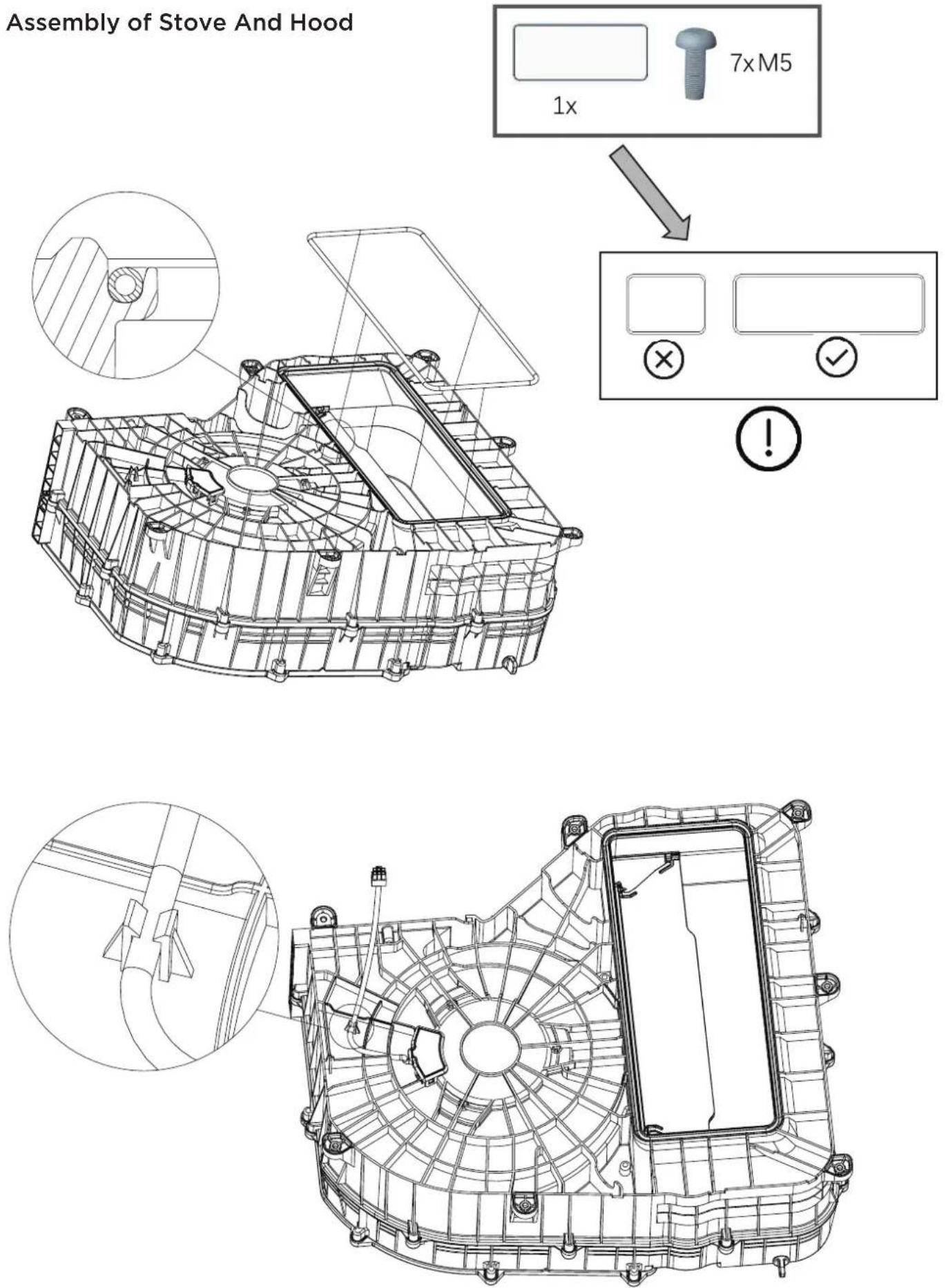
7×M5

4 × ST3.5
natural_image
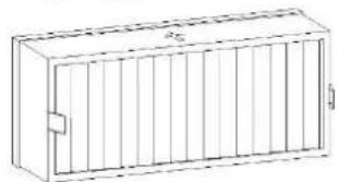
Line drawing of a rectangular enclosure with vertical slats and a small door (no text or symbols)2×
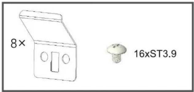
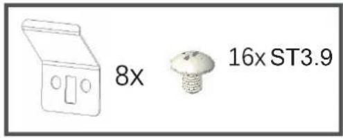
8×
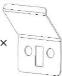
natural_image
Simple line drawing of a closed box with two circular cutouts and a rectangular slot (no text or symbols)
16xST3.9
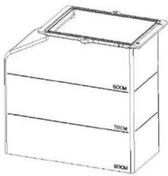
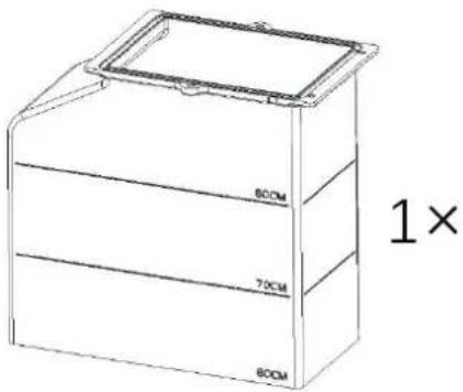
1×
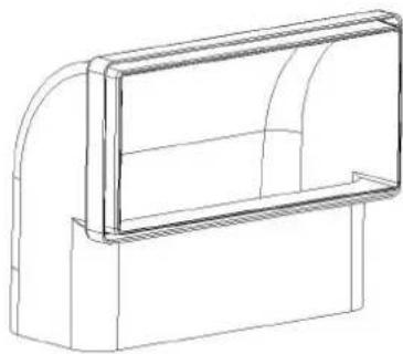
natural_image
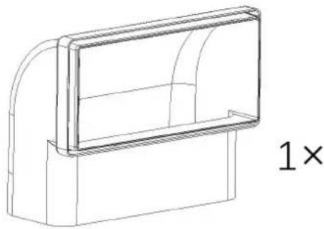
Line drawing of a 3D architectural or mechanical component with curved and rectangular sections (no text or symbols)1×
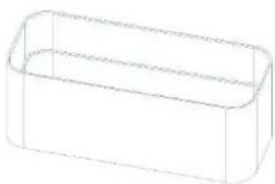
natural_image
Simple line drawing of a rectangular box (no text or symbols)1×
natural_image
Simple line drawing of a rectangular box or container (no text or symbols)1×
natural_image
Line drawing of a 3D pipe elbow joint (no text or symbols)1×
natural_image
Simple line drawing of a rectangular box or container (no text or symbols)1×
natural_image
Exploded view diagram of an electronic device showing internal components and assembly (no text or labels)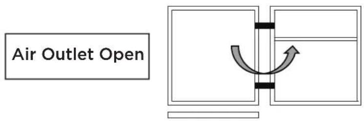
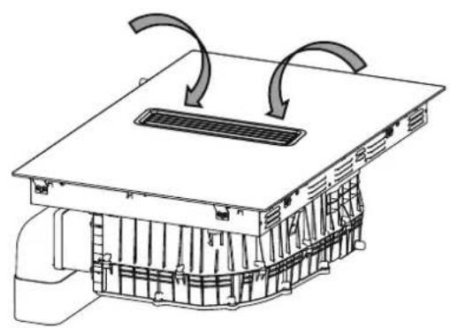
natural_image
Technical diagram of a mechanical ventilation system with airflow arrows (no text or labels)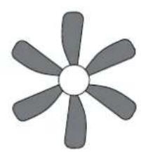
natural_image
Simple gray fan icon with six blades and a central hub (no text or symbols)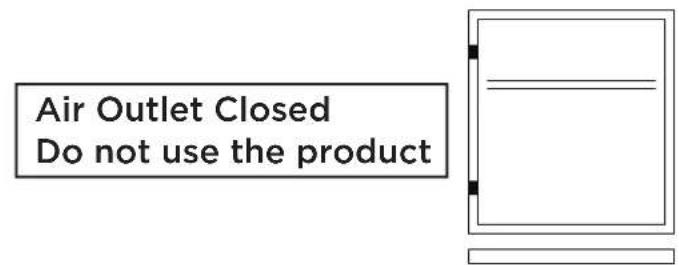
!
natural_image
Technical line drawing of a mechanical or electrical component with internal channels and a top cover (no text or symbols)
natural_image
Simple illustration of a six-bladed propeller with a central cross mark (no text or symbols)!
natural_image
Line drawing of a multi-compartment drawer arrangement with arrows indicating folding or assembly (no text or symbols)OK!
natural_image
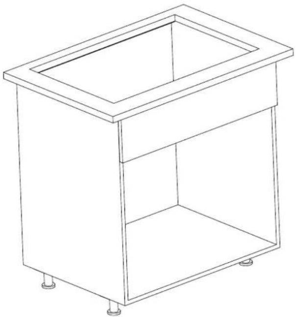
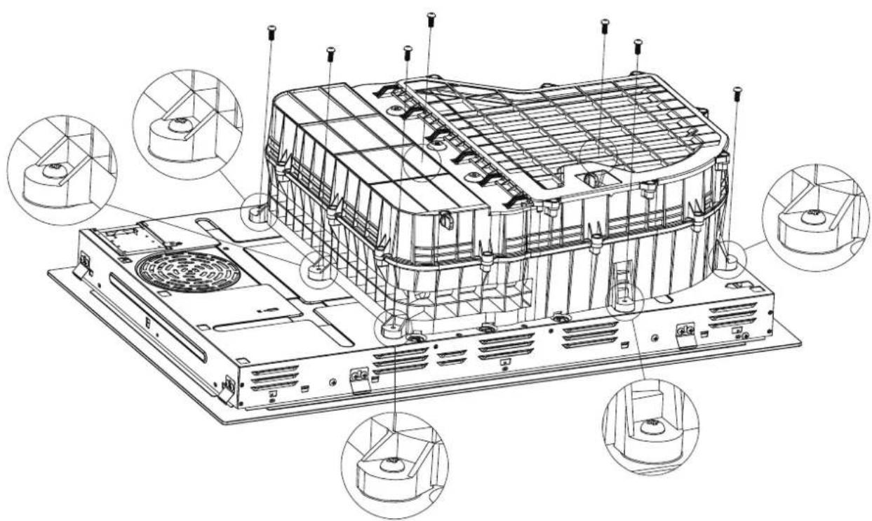
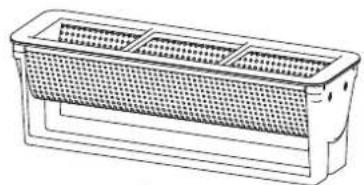
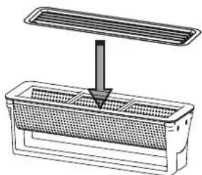
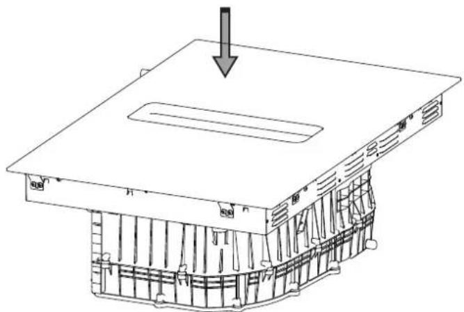
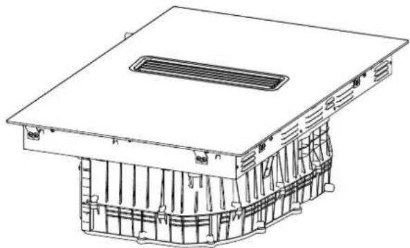
Line drawing of a rectangular kitchen sink with four legs (no text or symbols)Install Baffle On The Stove
natural_image
Technical line drawing of a computer chassis with internal components and mounting holes (no text or symbols)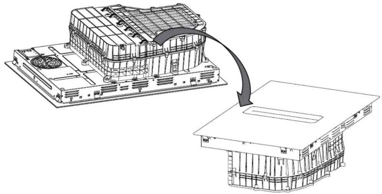
natural_image
Technical line drawing of an electronic device chassis with a magnified view showing internal components (no text or symbols)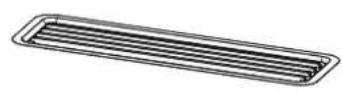
1x
natural_image
Line drawing of a rectangular container with internal mesh structure (no text or symbols)1x
②
natural_image
Diagram of a grating machine with a downward arrow indicating compression or cooling process (no text or symbols)①
natural_image
Technical line drawing of a mechanical component with a downward arrow indicating force or direction (no text or symbols present)
natural_image
Technical line drawing of a mechanical assembly with no visible text or symbolsOK!
natural_image
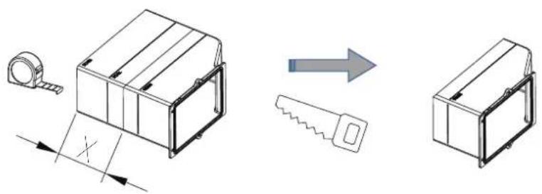
Technical illustration of a mechanical assembly with a magnifying glass, a cutting tool, and a separate view of a box (no text or symbols present)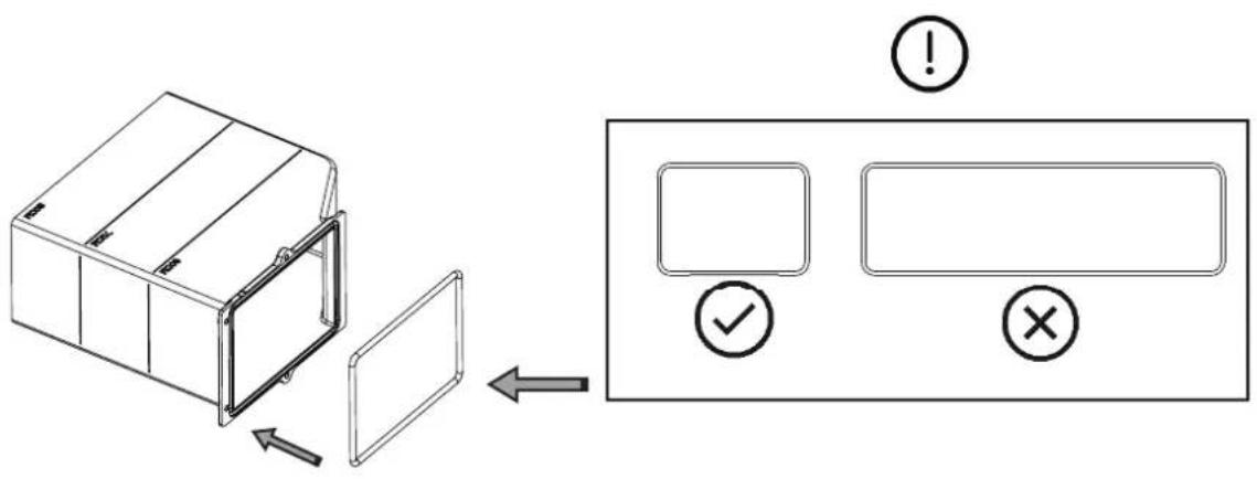
4x ST3.5
natural_image
Technical line drawing of a mechanical device with internal components and a circular component (no text or symbols)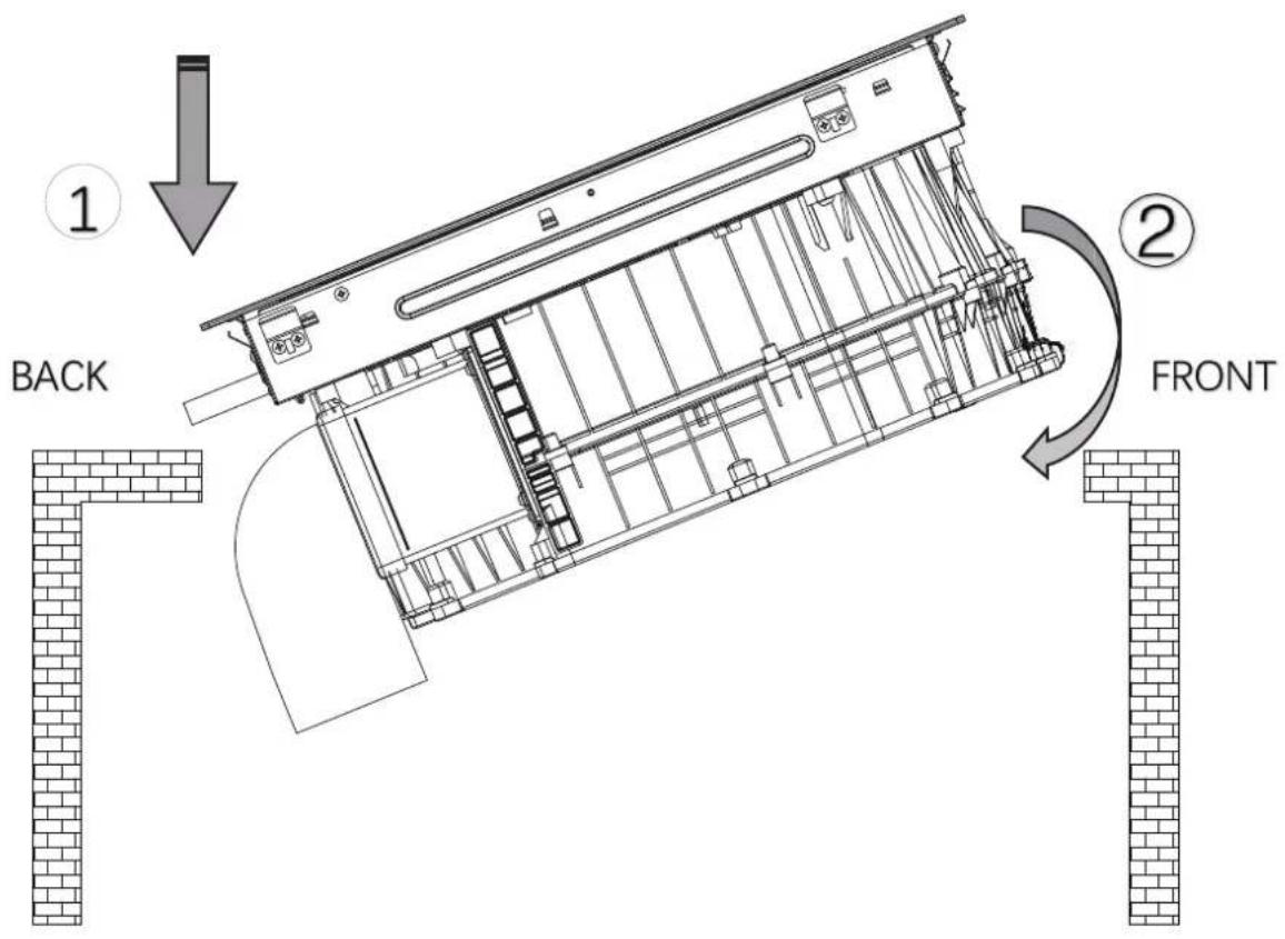
OK!
When water drainage is needed
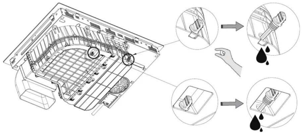
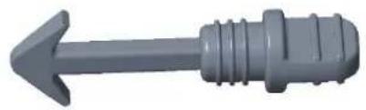
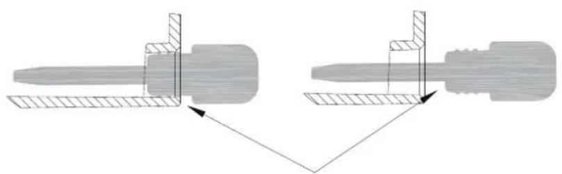
After draining water or installing the equipment, press the rubber plug tightly

natural_image
Gray 3D mechanical component with a left-pointing arrow (no text or symbols)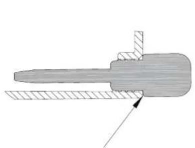
natural_image
Mechanical component diagram showing a lever and shaft assembly (no text or symbols)OK!
natural_image
Diagram showing two mechanical components with hatched areas and directional arrows indicating movement or assembly (no text or symbols)NG!

natural_image
Simple line icon of a house with arrows indicating direction, no text or symbols present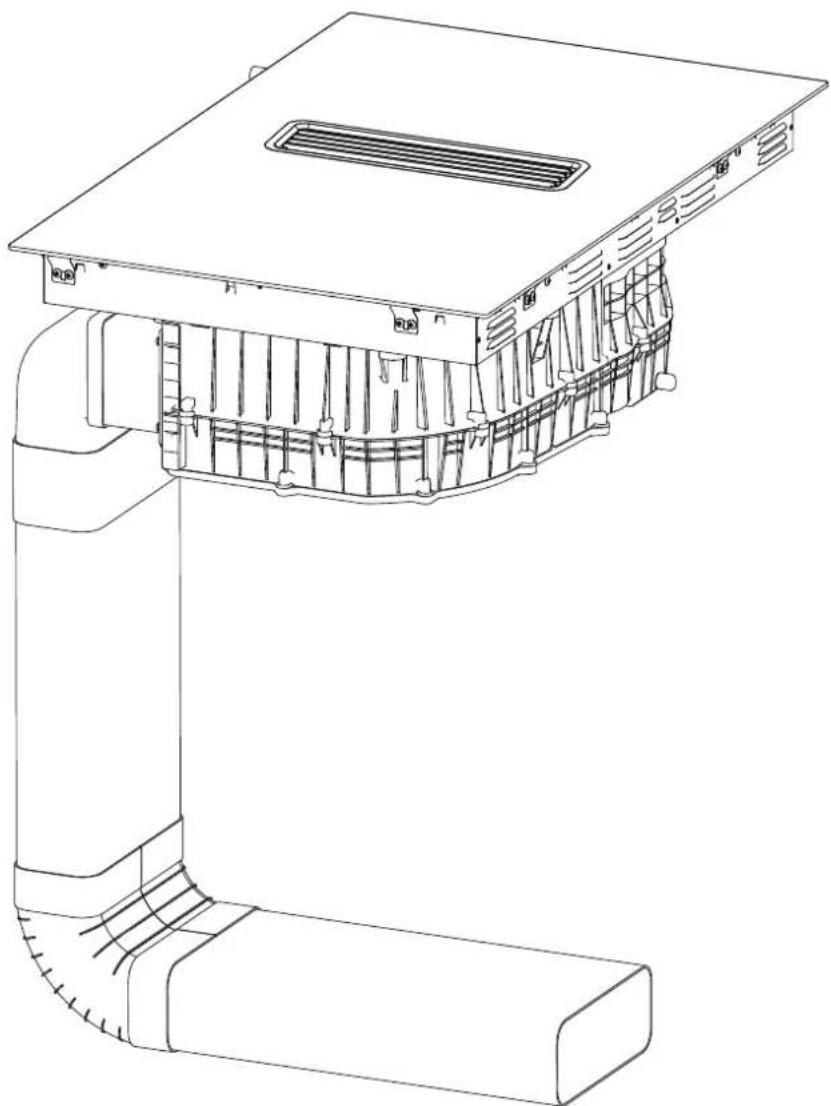
natural_image
Technical line drawing of a mechanical component with internal channels and mounting bracket (no text or symbols)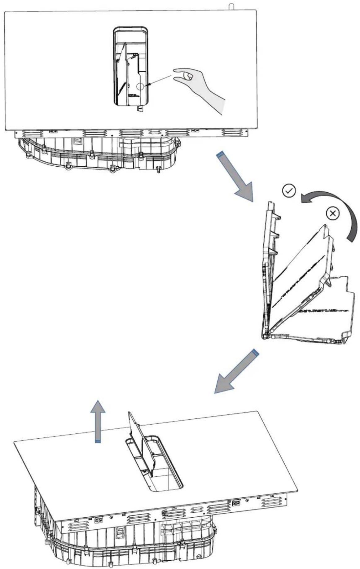
flowchart
graph TD
    A["Device with internal structure"] --> B["Assembly step 1: Folded part with hand icon"]
    B --> C["Assembly step 2: Folded part with checkmark and cross mark"]
    C --> D["Final packaging box with arrow indicating assembly direction"]
natural_image
Technical line drawing of a mechanical assembly with internal components and mounting brackets (no text or symbols)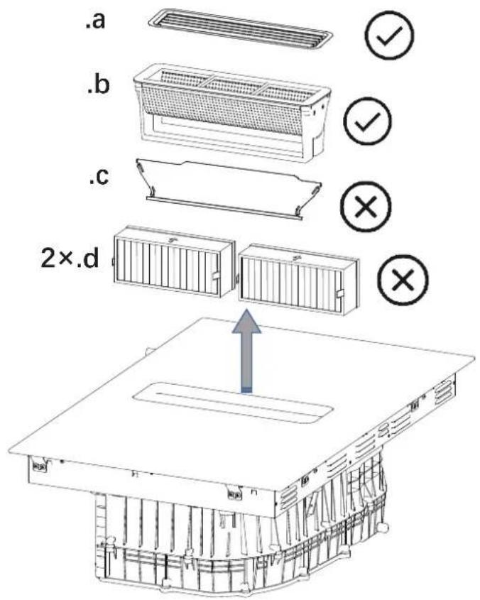
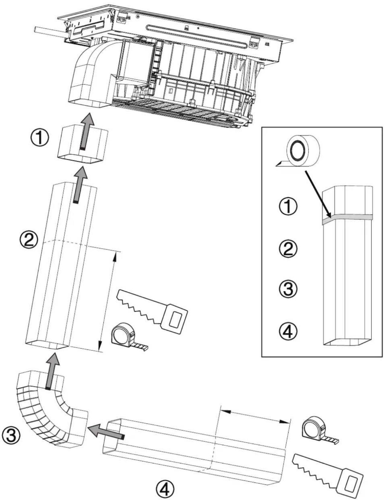
OK!
natural_image
Symbolic icon of a house with crossed and unshipped tools, no text or numbers present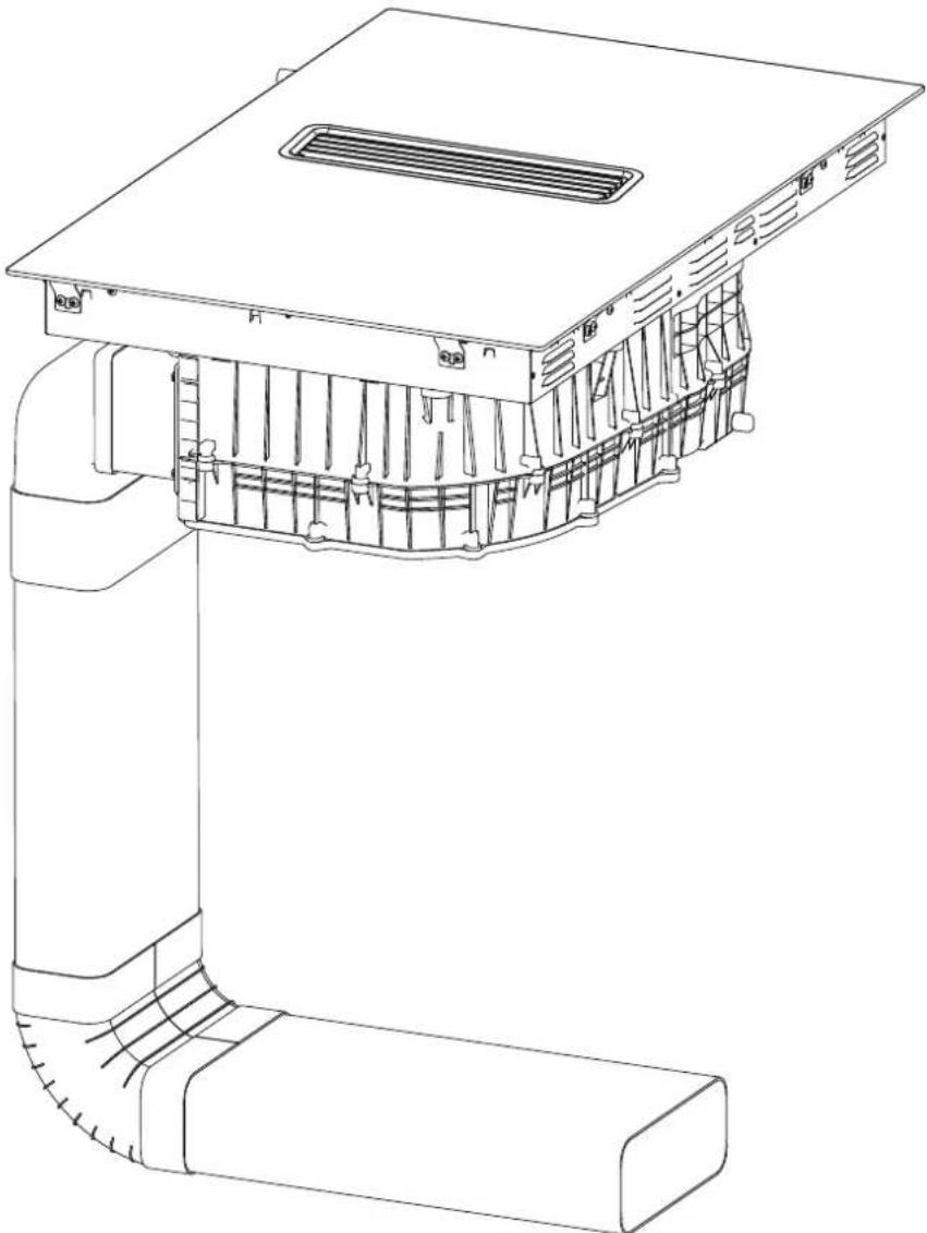
natural_image
Technical line drawing of a mechanical component with internal channels and mounting bracket (no text or symbols)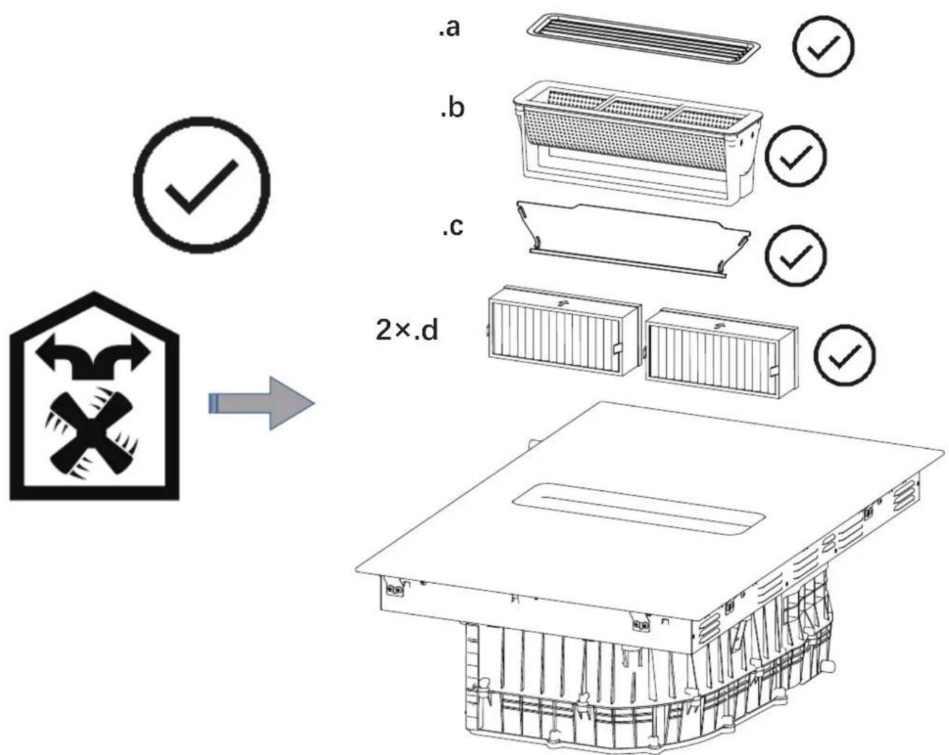
flowchart
graph TD
    A["Device with central component"] --> B["Inserting part"]
    B --> C["Assembly step 1"]
    C --> D["Assembly step 2"]
    D --> E["Final packaging"]
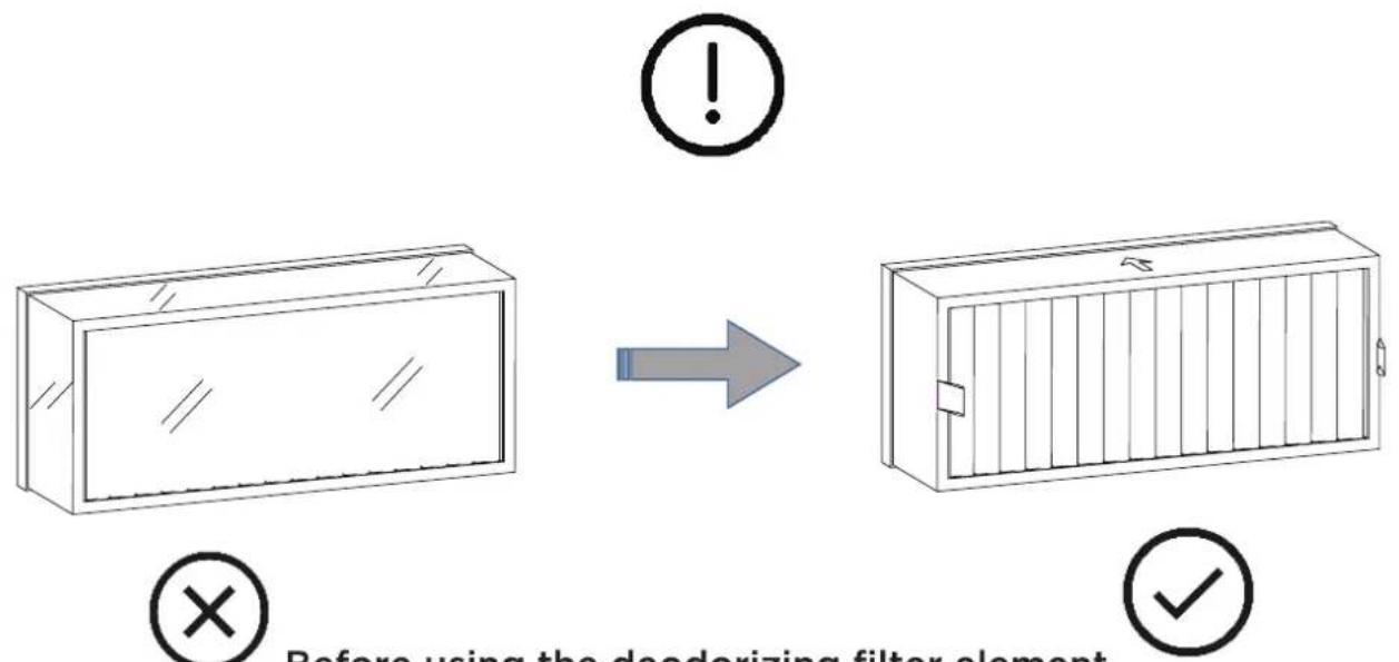
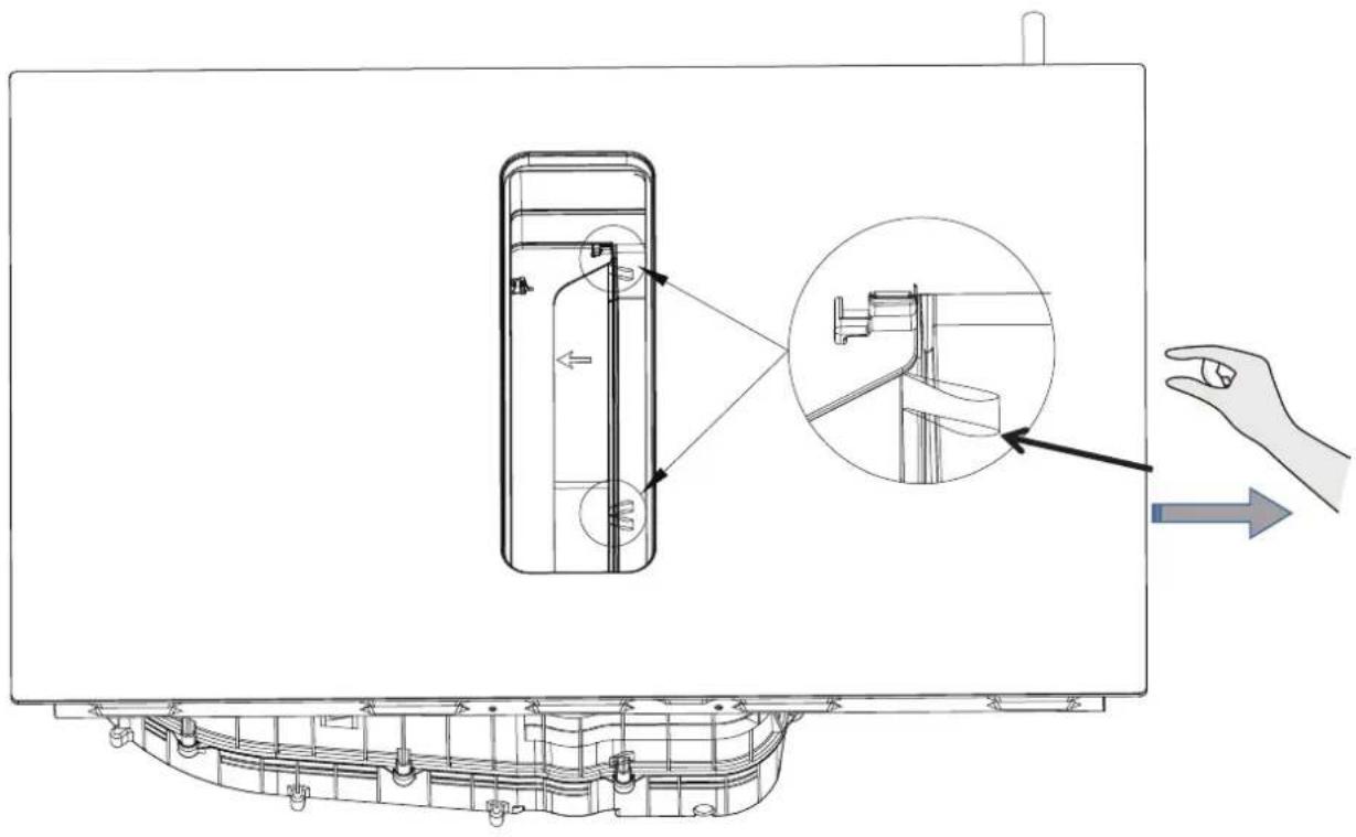
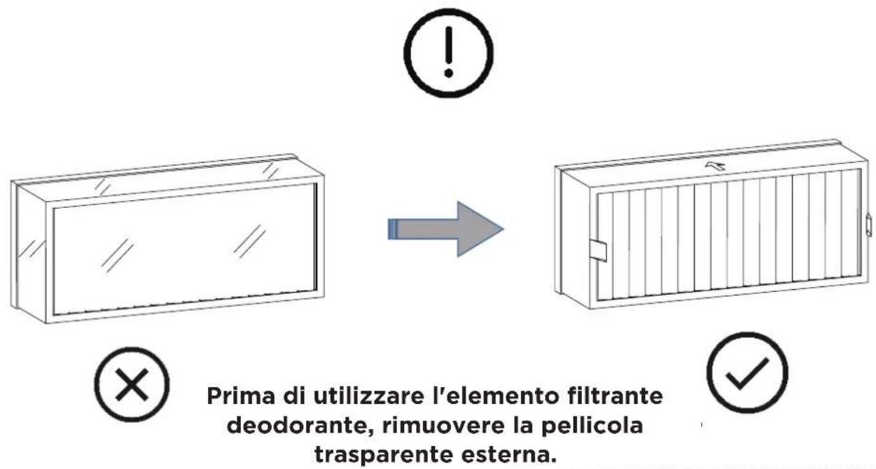
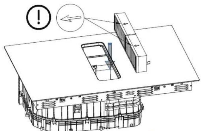
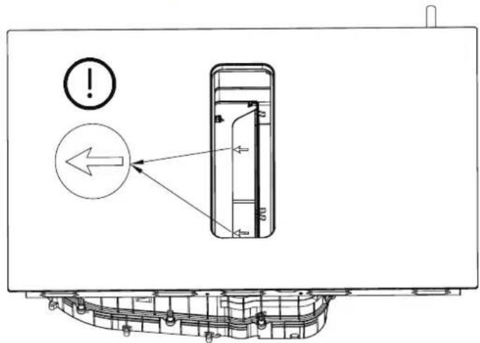
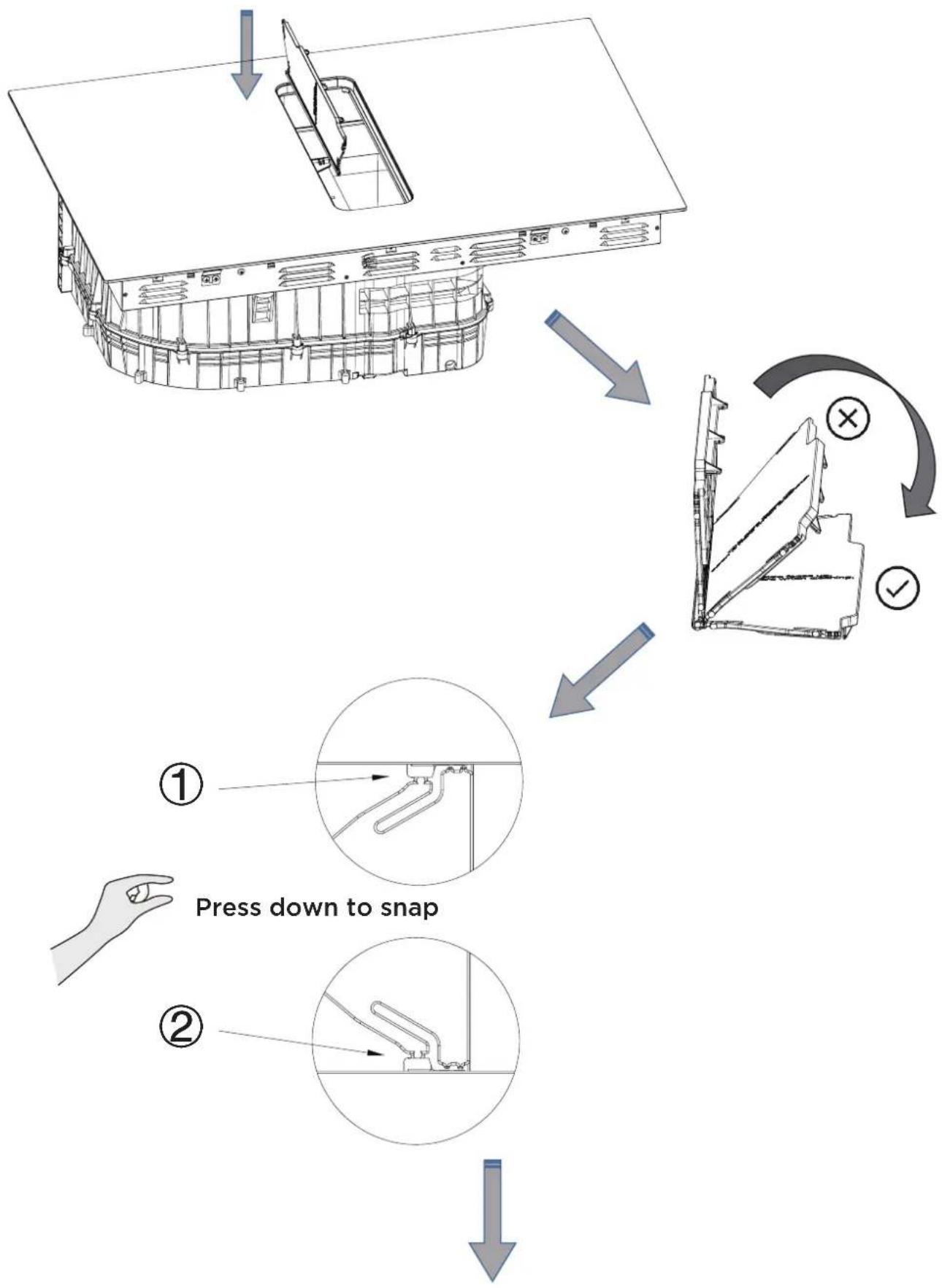
Before using the deodorizing filter element, tear off the outer transparent film.
flowchart
graph TD
    A["Press down to snap"] --> B["Step ①"]
    B --> C["Step ②"]
    C --> D["Step ③"]
    D --> E["Checkmark with X and ✓"]
    style A fill:#f9f,stroke:#333
    style B fill:#ccf,stroke:#333
    style C fill:#cfc,stroke:#333
    style D fill:#fcc,stroke:#333
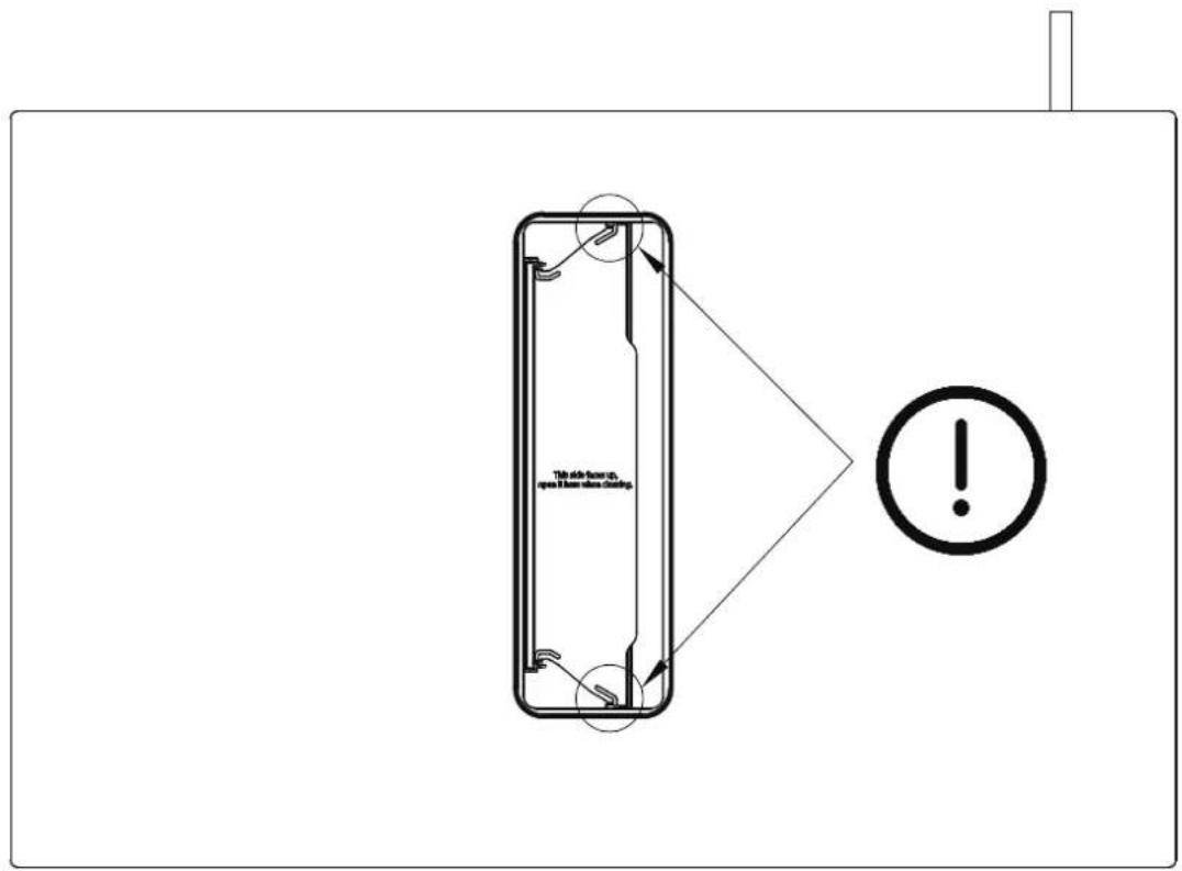
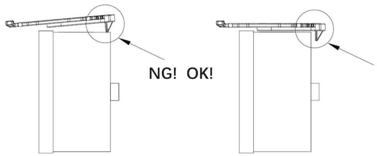
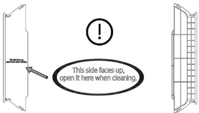
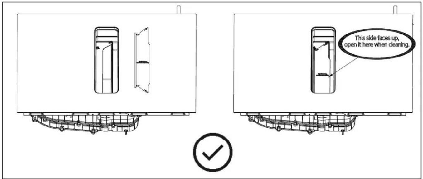
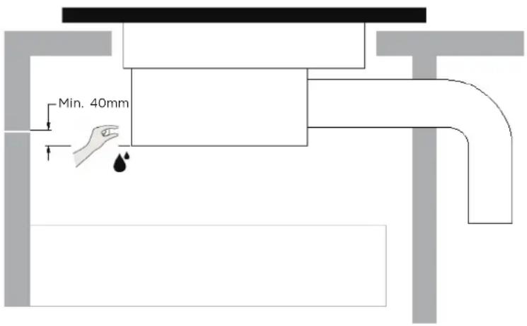
WARNING: Ensuring Adequate Ventilation
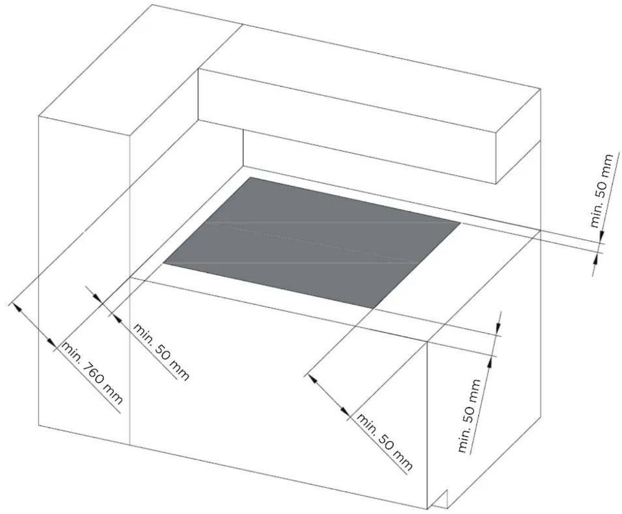
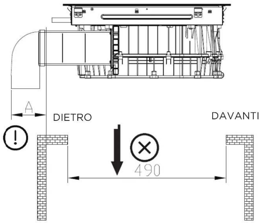
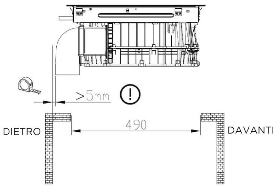
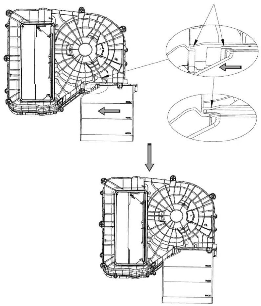
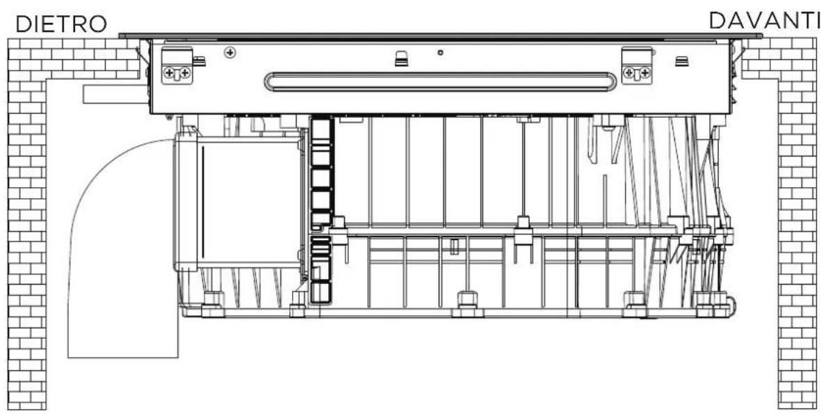
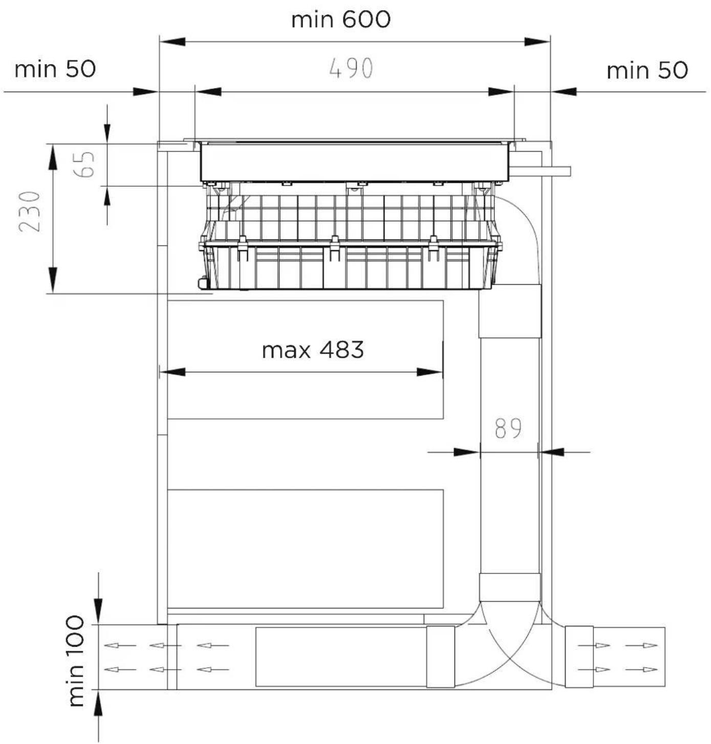
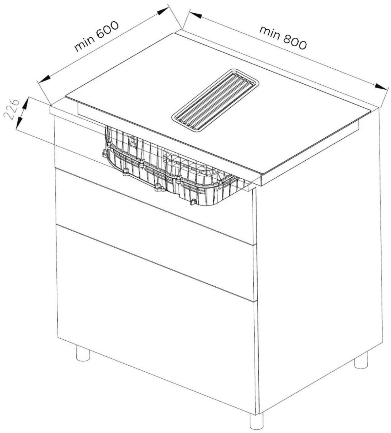
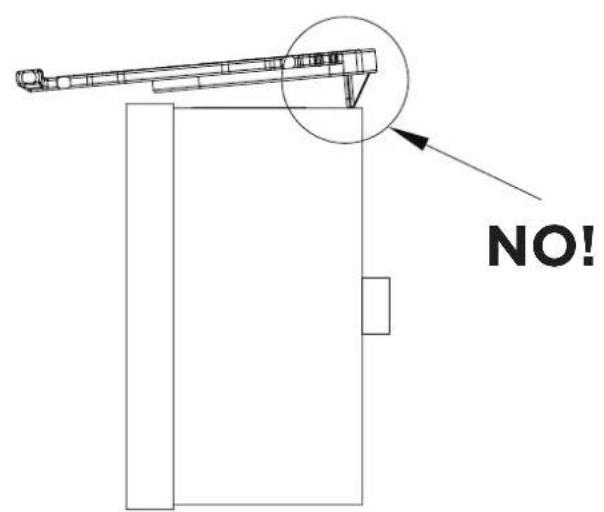
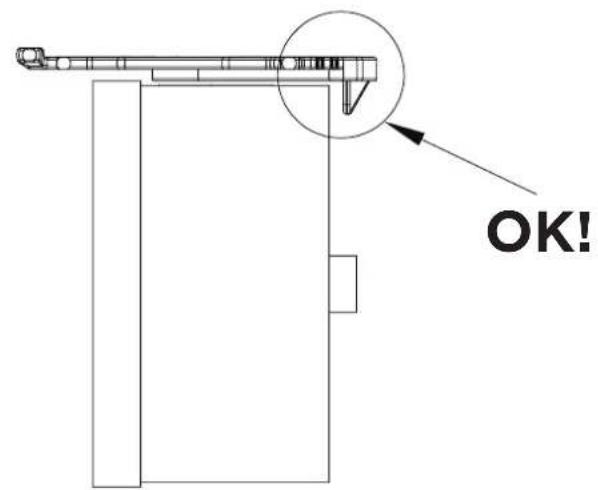
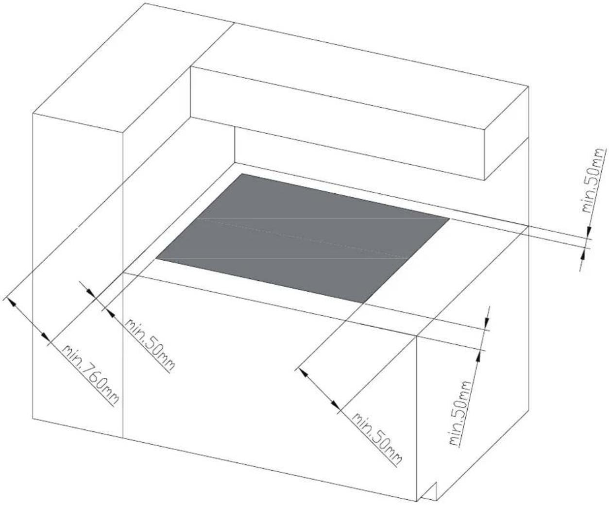
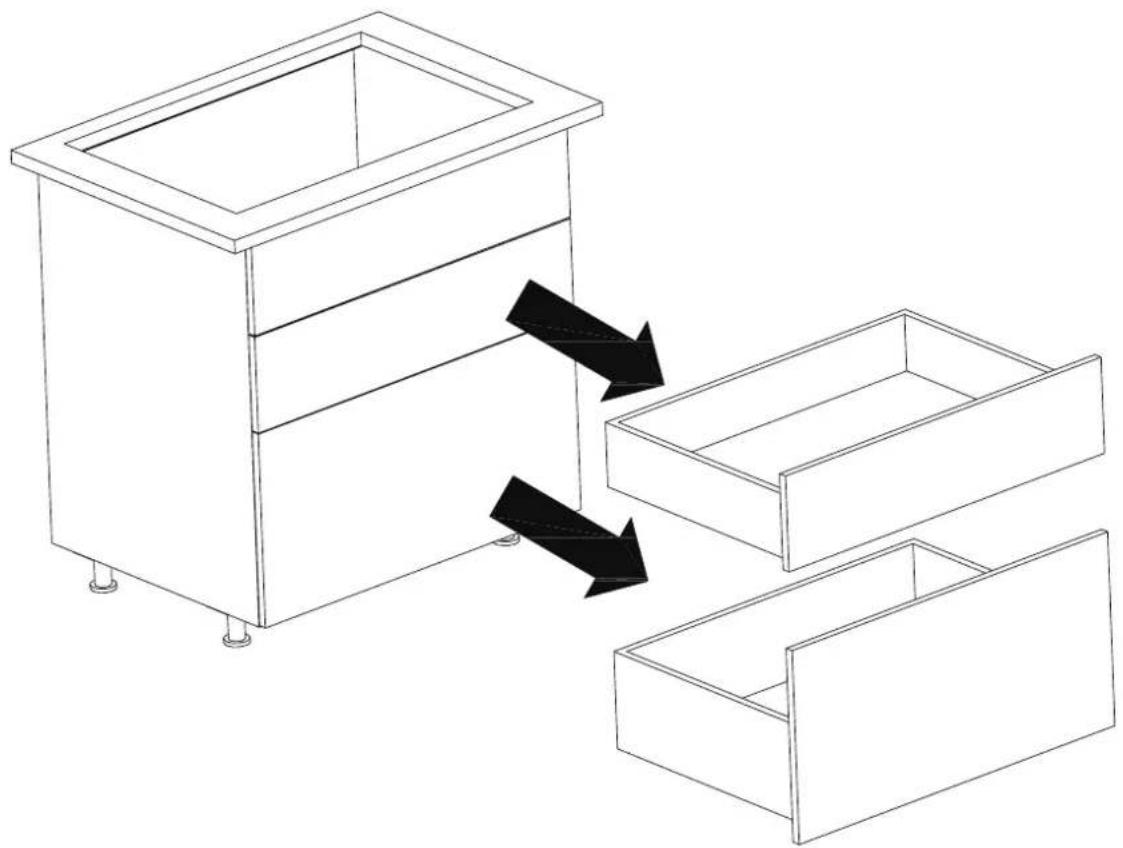
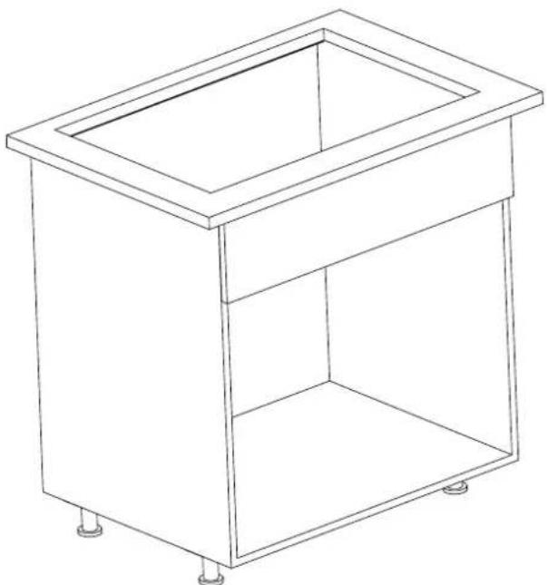
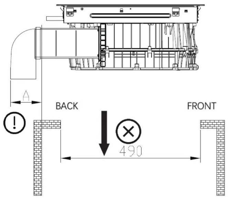
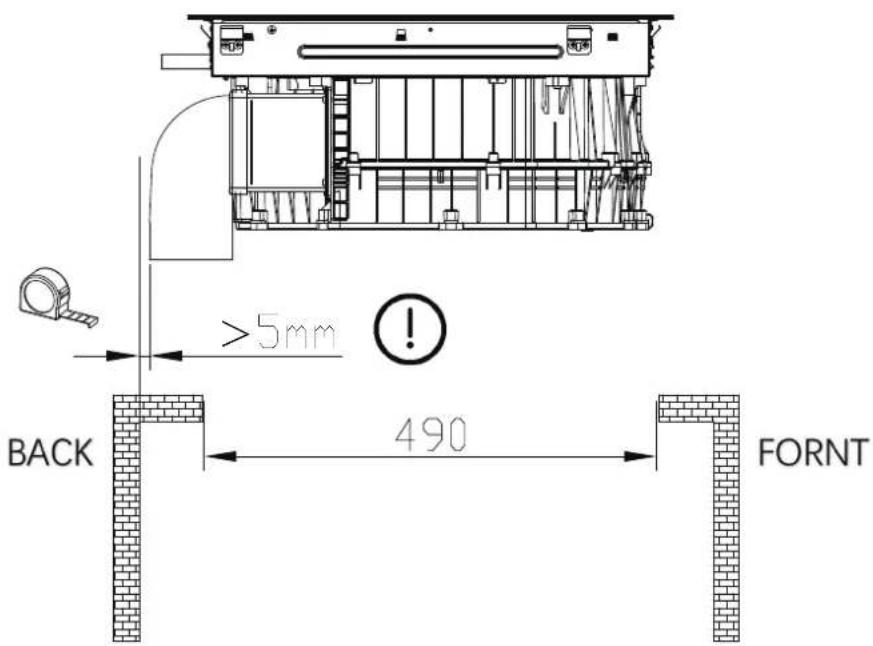
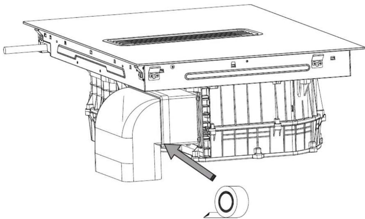
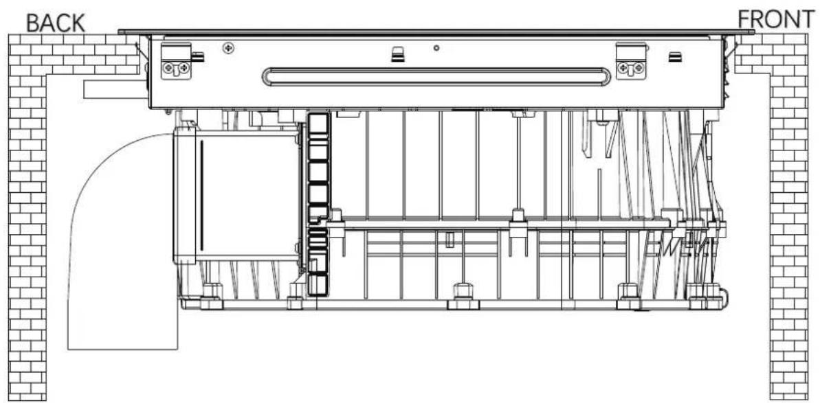
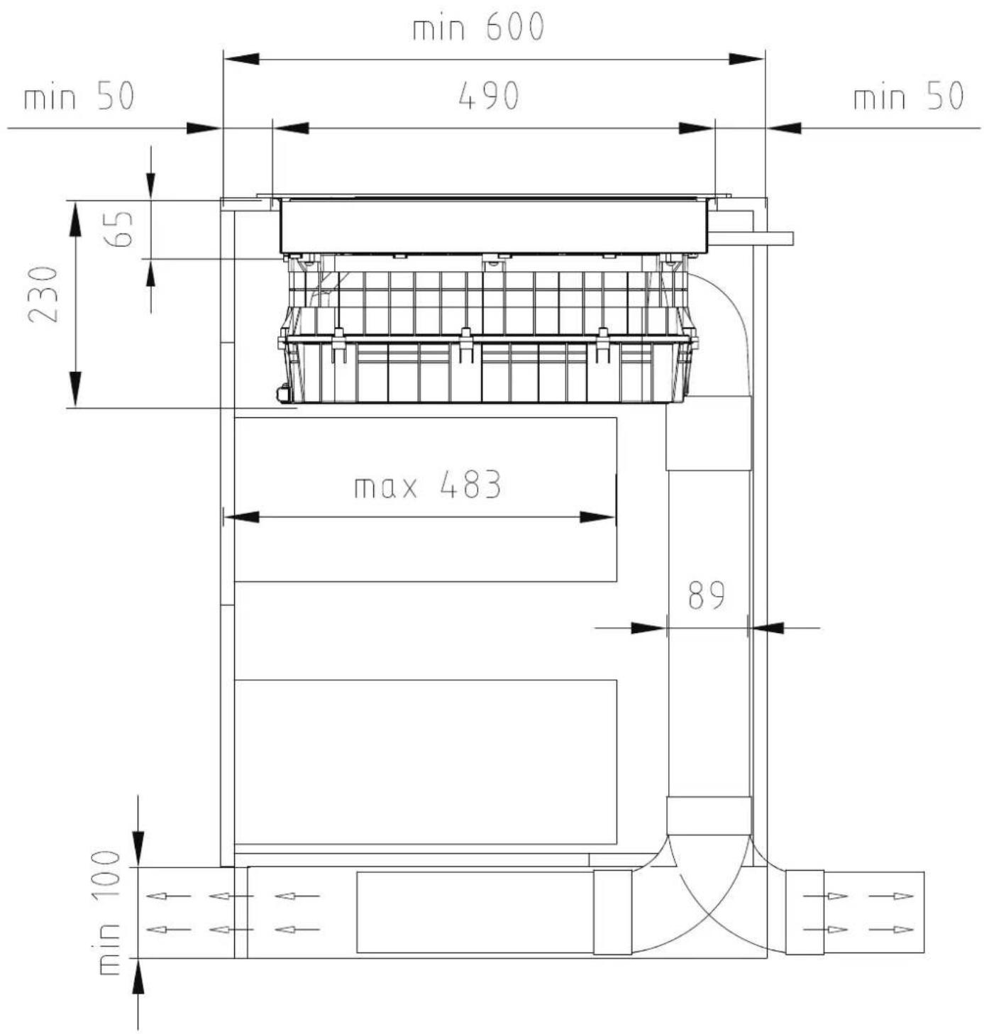
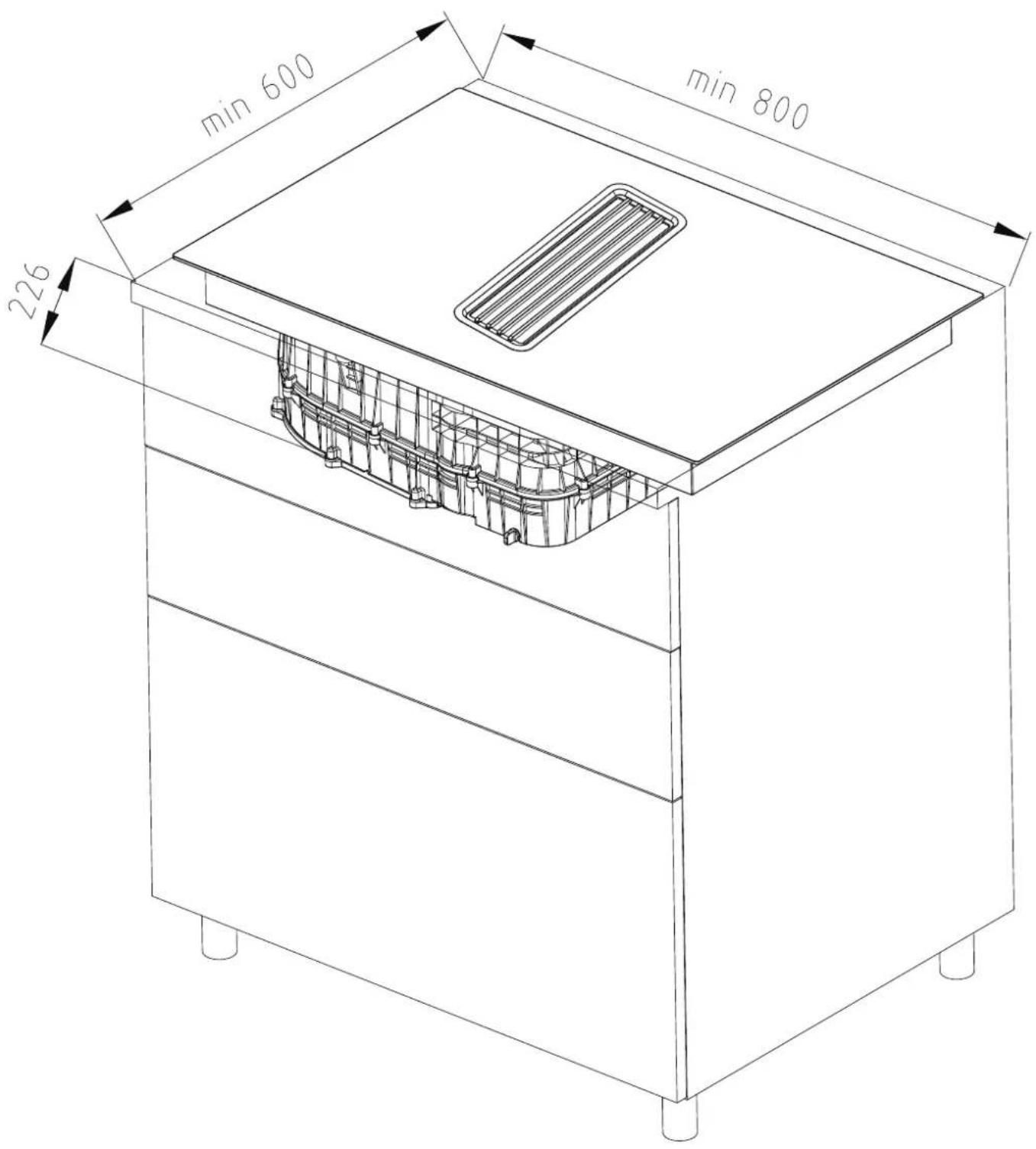
In order to drain liquids conveniently, it is necessary to keep a minimum distance of 40mm between the baffle and the bottom of the hob. Follow the requirements below.
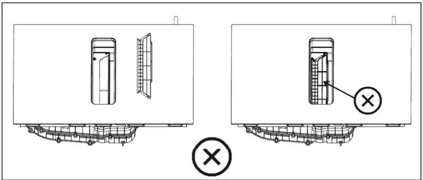
There are ventilation holes around outside of the hob. YOU MUST ensure these holes are not blocked by the worktop when you put the hob into position.
- Be aware that the glue that join the plastic or wooden material to the furniture, has to resist to temperature not below 150°C, to avoid the unstuck of the paneling. - The rear wall, adjacent and surrounding surfaces must therefore be able to withstand an temperature of 90°C.
Before Installing the Hob, Make Sure That
- The work surface is square and level, and no structural members interfere with space requirements.
- The work surface is made of a heat-resistant and insulated material.
- If the hob is installed above an oven, the oven has a built-in cooling fan.
- The installation will comply with all clearance requirements and applicable standards and regulations.
- A suitable isolating switch providing full disconnection from the mains power supply is incorporated in the permanent wiring, mounted and positioned to comply with the local wiring rules and regulations.
- The isolating switch must be of an approved type and provide a 3 mm air gap contact separation in all poles (or in all active [phase] conductors if the local wiring rules allow for this variation of the requirements).
- The isolating switch will be easily accessible to the customer with the hob installed.
- You consult local building authorities and by-laws if in doubt regarding installation.
- You use heat-resistant and easy-to-clean finishes (such as ceramic tiles) for the wall surfaces surrounding the hob.
After Installing the Hob, Make Sure That
- The power supply cable is not accessible through cupboard doors or drawers.
- There is adequate flow of fresh air from outside the cabinetry to the base of the hob.
- If the hob is installed above a drawer or cupboard space, a thermal protection barrier is installed below the base of the hob.
- The isolating switch is easily accessible by the customer.
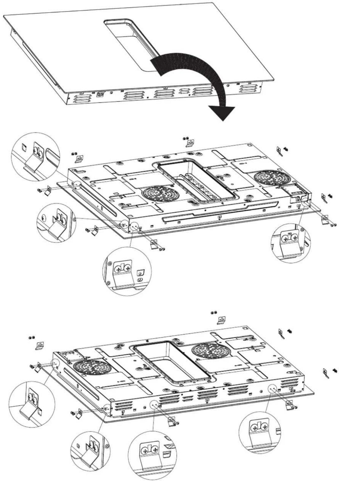
Before Locating the Fixing Brackets
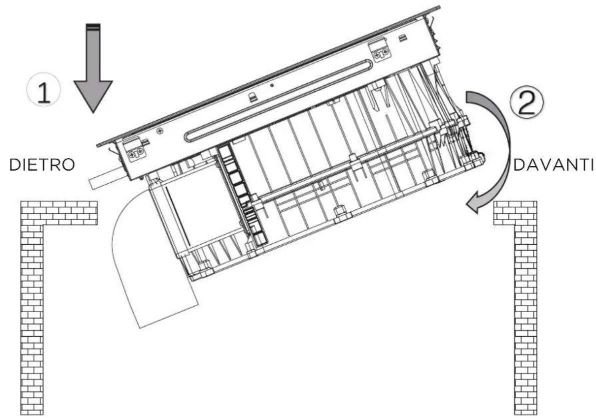
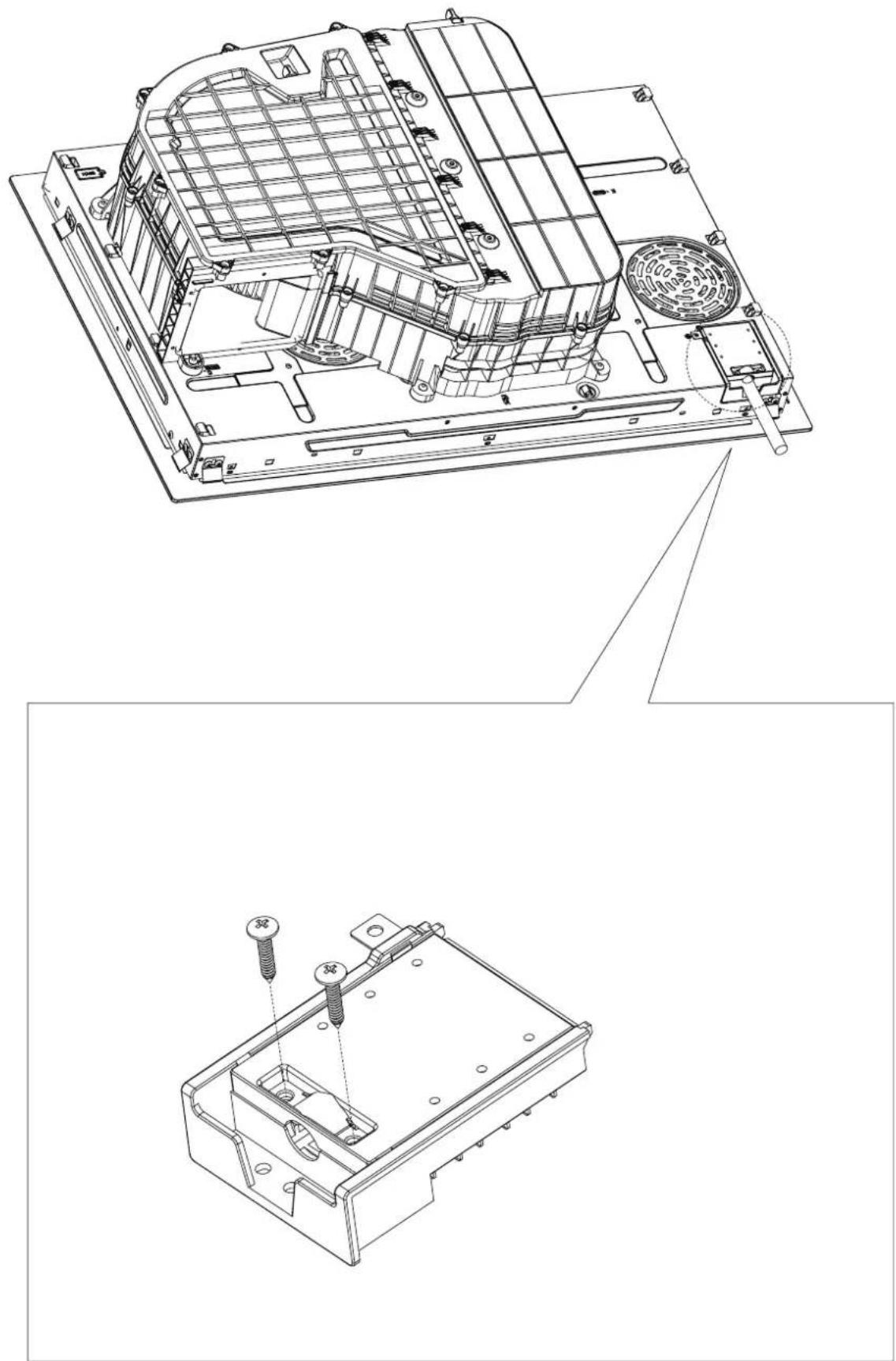
The unit should be placed on a stable, smooth surface (use the packaging). Do not apply force onto the controls protruding from the hob.

CAUTIONS
- The induction hotplate must be installed by qualified personnel or technicians. We have professionals at your service. Please never conduct the operation by yourself.
- The hob will not be installed directly above a dishwasher, fridge, freezer, washing machine or clothes dryer, as the humidity may damage the hob electronics
- The induction hotplate shall be installed such that better heat radiation can be ensured to enhance its reliability.
- The wall and induced heating zone above the table surface shall withstand heat.
- To avoid any damage, the sandwich layer and adhesive must be resistant to heat.
- A steam cleaner is not to be used.
Connecting the Hob to the Mains Power Supply

This hob must be connected to the mains power supply only by a suitably qualified person. Before connecting the hob to the mains power supply, check that:
- The domestic wiring system is suitable for the power drawn by the hob.
- The voltage corresponds to the value given in the rating plate
- The power supply cable sections can withstand the load specified on the rating plate.
To connect the hob to the mains power supply, do not use adapters, reducers, or branching devices, as they can cause overheating and fire.
The power supply cable must not touch any hot parts and must be positioned so that its temperature will not exceed 75^ C at any point.

Check with an electrician whether the domestic wiring system is suitable without alterations. Any alterations must only be made by a qualified electrician.

- If the total number of heating unit of the appliance you choose is not less than 4, the appliance can be connected directly to the mains by single-phase electric connection, as shown below.
- If the cable is damaged or to be replaced, the operation must be carried out the by after-sale agent with dedicated tools to avoid any accidents.
- If the appliance is being connected directly to the mains an omnipolar circuit-breaker must be installed with a minimum opening of 3mm between contacts.
- The installer must ensure that the correct electrical connection has been made and that it is compliant with safety regulations.
• The cable must not be bent or compressed. - The cable must be checked regularly and replaced by authorised technicians only.
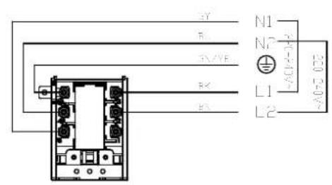
220-240V-/380-415V 3N-
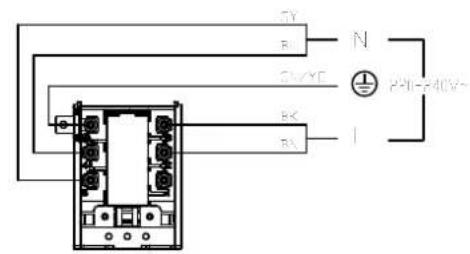
220-240V 1N-
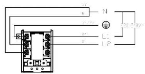
220-240V-/380-415V 3N-

The bottom surface and the power cord of the hob are not accessible after installation.
OPERATION INSTRUCTIONS
Touch Controls
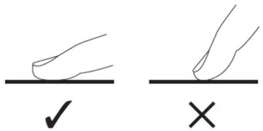
- The controls respond to touch, so you don't need to apply any pressure.
- Use the ball of your finger, not its tip.
- You will hear a beep each time a touch is registered.
- Make sure the controls are always clean, dry, and that there is no object (e.g. a utensil or a cloth) covering them. Even a thin film of water may make the controls difficult to operate.
Choosing the Right Cookware

- Only use cookware with a base suitable for induction cooking.
Look for the induction symbol on the packaging or on the bottom of the pan.
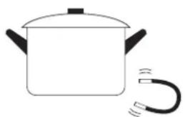
- You can check whether your cookware is suitable by carrying out a magnet test.
Move a magnet towards the base of the pan. If it is attracted, the pan is suitable for induction.
- If you do not have a magnet:
-
Put some water in the pan you want to check.
-
If U does not flash in the display and the water is heating, the pan is suitable.
- Cookware made from the following materials is not suitable: pure stainless steel, aluminium or copper without a magnetic base, glass, wood, porcelain, ceramic, and earthenware.
natural_image
Simple line drawing of a cooking pot with a coiled tube (no text or symbols)- Do not use cookware with jagged edges or a curved base.
natural_image
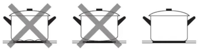
Three identical cooking pots with crossed-out kitchen panes, no text or symbols present- Make sure that the base of your pan is smooth, sits flat against the glass, and is the same size as the cooking zone. Use pans whose diameter is as large as the graphic of the zone selected. Using a pot a slightly wider energy will be used at its maximum efficiency. If you use smaller pot efficiency could be less than expected. Pot less than 140 mm could be undetected by the hob. Always centre your pan on the cooking zone.

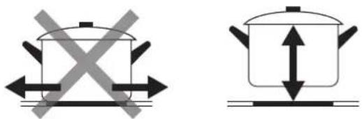
• Always lift pans off the Induction hob – do not slide, or they may scratch the glass.
natural_image
Two cooking pots with crossed arrows indicating heating or resistance, one above and one below (no text or symbols)How to Use
Start Cooking
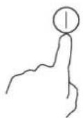
Touch the ON/OFF control for 1 seconds. After power on, the buzzer beeps once, all displays show “-”, indicating that the induction hob has entered the state of standby mode.
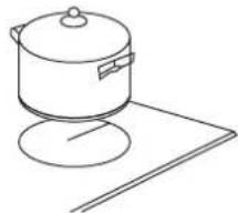
Place a suitable pan on the cooking zone that you wish to use.
• Make sure the bottom of the pan and the surface of the cooking zone are clean and dry.
natural_image
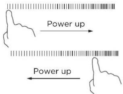
Line drawing of a cooking pot on a stand (no text or symbols)Select a heat setting by touching the slider control
- You can modify the heat setting at any time during cooking.
If the display flashes ÷ alternately with the heat setting
This means that:
- you have not placed a pan on the correct cooking zone or,
- the pan you're using is not suitable for induction cooking or,
- the pan is too small or not properly centered on the cooking zone.
No heating takes place unless there is a suitable pan on the cooking zone.
The display will automatically turn off after 1 minutes if no suitable pan is placed on it.
Manual ventilation control
You can control the ventilation setting manually.

NOTE
Using tall items of cookware may prevent the ex-traction system from working at optimum power. You can improve the extraction power by placing the lid on the cookware at an angle.
Activating the manual ventilation control
- In the power-on state, touch key to activate the ventilation system;
- Short press the hood key to switch levels from 0-3, long press the hood key for 3s to close the hood.
- Touch Ⓑ to switch to boost level.
The ventilation system is activated.
Changing or deactivating manual ventilation control
-
Power off
-
Using the hood key 📋 to adjust the level to 0
Finish Cooking
Turn the cooking zone off by touching the slider to "O". Make sure the display shows "O".
Turn the whole cooktop off by touching the ON/OFF control.
0
Run-on function for the ventilation system
ventilation system is divided into manual and automatic modes.
The automatic mode can be enabled after all the hob is enabled. It will be automatically disabled two minutes after the hob is all shut down.
Manually
In power on states, touch 🎨 or Ⓐ. digital screen display level 0-3 or b.
Automatically
In power on states, Touch Ⓐ, digital screen display A.
The appliance deactivates the run-on function when:
• 2 minutes after all hobs are shut down.
- press power key.
Using the Boost function Activate the boost function
Touching the max button. Make sure the display shows the marquee action.
B
Cancel the Boost function
Touching the heating zone slider control that you wish to cancel the boost function.
0 15
Turn the whole cooktop off by touching the ON/OFF control.
- The function can work in any cooking zone.
- The cooking zone returns to its original setting after 5 minutes.
- If the original heat setting equals 0, it will return to max digital level after 5 minutes.
- If the LF hob is set to boost and then the LR hob is set to boost, the LF LR is set to 15 level.
Intensive ventilation setting
- The ventilation system has intensive modes. If you activate the intensive settings, the ventilation systemworks at maximum output.
- Activating the intensive ventilation setting.
• 1. Touch Ⓑ.
• 2. Display "b" on the digital tube. - Changing or deactivating the intensive ventilation setting.
- Using key to select the required performance level in the settings area or set it to 0.
Automatic start for the ventilation system
If you select a power level for a cooking zone and the auto-matic start switches on.
The ventilation system switches on at a power level in accordance with the respective power level for the cooking zones.
Flexible Area
- This area can be used as a single zone or as two different zones, accordingly to the cooking needs anytime.
- Flexible area is made of two independent inductors that can be controlled separately. When working as a single zone, the part that is not covered by cookware is automatically switched off after 8 seconds.
- To grant a correct pan detection and a even heat distribution, the cookware should be correctly placed:
- In the front or rear side of the flexible zone when the cookware is smaller than 21 cm.
- Anywhere with bigger cookware.
As big zone
To activate the flexible area as a single big zone, simply press the Flexible Area control.
I
The power setting works as any other normal area.
To add a further pot, press again the dedicated keys, in order to detect the cookware.
As two independent zones
To use the flexible area as two different zones with different power settings, press the Flexible Area control.
Locking the Controls
- You can lock the controls to prevent unintended use (for example children accidentally turning the cooking zones on).
- When the controls are locked, all the controls except the ON/OFF control are disabled.
To lock the controls
Touch and hold the Lock control for 3 seconds.
The digital tube displays "Lo"
To unlock the controls
Touch and hold the Lock control for 3 seconds.

When the hob is in the lock mode, all the controls are disable except the ON/OFF ⏻, you can always turn the induction hob off with the ON/OFF ⏻ control in an emergency, but you shall unlock the hob first in the next operation.
Power Management Function
- it is possible to set a maximum power absorption level for the induction hob, choosing up to different power ranges.
- Induction hobs are able to limit themselves automatically in order to work at lower power level, to avoid the risk of overloading.
To enter Power Management Function
State: Set Child Lock in power off state Entry conditions:
1) LR max Burner MAX select key 3 seconds(+Buzzer sound)
2) LF max BurnerMAX select key 3 seconds(+Buzzer sound)
Set working:
Set working:


To switch to another level
1) Select the power limit value with the lock key ☐ (the range of power limit value selection is based on Spec)
There are 5 power levels, from "2.8kW" to "7.4kW". The LF and RF digita display will show one of them.
"28 00": the maximum power is 2.8kW.
"35 00": the maximum power is 3.5kW.
"45 00": the maximum power is 4.5kW.
"58 00": the maximum power is 5.8kW.
"74 00": the maximum power is 7.4kW.
Confirmation and Exit Power Management Function
After select power limit value, use power off key ⏻ for confirmation.
Then the hob will be turned off.
Timer control
- You can set it to turn one or more cooking zones off after the set time is up.
- The maximum timing time is the default running time of the current running level, please refer to Default working times table.
Setting the timer to turn cooking zones off
Set one zone
Touching the heating zone slider control.
0 15
Set the time by touching the or control of the timer.
Hint: Touch the “-” or “+” control of the timer once will decrease or increase by 1 minute. Touch and hold the “-” or “+” control of the timer will decrease or increase by 10 minutes.
- +
When the time is set, it will begin to count down immediately. The display will show the remaining time.
When cooking timer expires, the corresponding cooking zone will be switched off automatically.
0:30
Set more zones:
The steps for setting more zones are similar to the steps of setting one zone; The timing of each heating zone is independently set and displayed The show as below:
 15 Ⓑ 8:8:8 - + ⓐ - + 8:8:8 0  15 Ⓑ • □ I 0  15 Ⓑ 8:8:8 - + 🌿 ⓑ - + 8:8:8 0  15 Ⓑ ①](/content/2026/05/915597/images/4a927ad4fa020506fe6c12e8a17b1a060d9b288cd78e1931fd7c5c600d07e873.jpg)
Cancel the timer
The timing time of the operation corresponding to the heating zone to 0:00.
- +
Touch and hold the timer control “-” and “+” for 1s, the timer will be cancel.
- +

NOTE
1) The manual timing setting cannot exceed the default timing time of the stove head. If the current level value is reduced after the maximum timing time is set, the timing time will automatically change to the default maximum time of the current level when the timing time is greater than the default closing time of the current level.
2) Under the timing display state, click the slider once to view the current heating level. After entering the display mode of level, click or slide the slider to set the level
Default working times
Auto shut down is a safety protection function for your induction hob and hood. It shut down automatically if ever you forget to turn off your cooking. The default working times for various power levels are shown in the below table:
Induction hob:
| Power level 1 | 2 | 3 | 4 | 5 | 6 | 7 | 8 | 9 | |
| Default working timer (min) | 480 | 480 | 480 | 360 | 360 | 360 | 240 | 240 | 240 |
| Power level 10 | 11 | 12 | 13 | 14 | 15 | ||||
| Default working timer (min) | 120 | 120 | 120 | 90 | 90 | 90 |
Hood:
| Power level 1 | 2 | 3 | |
| Default working timer (min) | 480 | 240 | 120 |

People with a heart pace maker should consult with their doctor before using this unit.
CLEANING AND MAINTENANCE
To keep your appliance working efficiently for a longtime, it is important to clean and maintain it carefully.
Cleaning the Hob
| What? How? Important! | ||
| Everyday soiling on glass. (fingerprints, marks, stains left by food or non-sugary spillovers on the glass) | 1. Switch the power to the cooktop off.2. Apply a cooktop cleaner while the glass is still warm (but not hot!)3. Rinse and wipe dry with a clean cloth or paper towel.4. Switch the power to the cooktop back on. | ·When the power to the cooktop is switched off, there will be no ‘hot surface’ indication but the cooking zone may still be hot! Take extreme care.·Heavy-duty scourers, some nylon scourers and harsh/abrasive cleaning agents may scratch the glass. Always read the label to check if your cleaner or scourer is suitable.·Never leave cleaning residue on the cooktop: the glass may become stained. |
| Boilovers, melts, and hot sugary spills on the glass. | Remove these immediately with a fish slice, palette knife or razor blade scraper suitable for Induction glass cooktops, but beware of hot cooking zone surfaces:1. Switch the power to the cooktop off at the wall.2. Hold the blade or utensil at a 30° angle and scrape the soiling or spill to a cool area of the cooktop.3. Clean the soiling or spill up with a dish cloth or paper towel.4. Follow steps 2 to 4 for ‘Everyday soiling on glass’ above. | ·Remove stains left by melts and sugary food or spillovers as soon as possible. If left to cool on the glass, they may be difficult to remove or even permanently damage the glass surface.·Cut hazard: when the safety cover is retracted, the blade in a scraper is razor-sharp. Use with extreme care and always store safely and out of reach of children. |
| Spillovers on the touch controls. | 1. Switch the power to the cooktop off.2. Soak up the spill3. Wipe the touch control area with a clean damp sponge or cloth.4. Wipe the area completely dry with a paper towel.5. Switch the power to the cooktop back on. | ·The cooktop may beep and turn itself off, and the touch controls may not function while there is liquid on them. Make sure you wipe the touch control area dry before turning the cooktop back on. |
Components To Be Cleaned Or Replaced
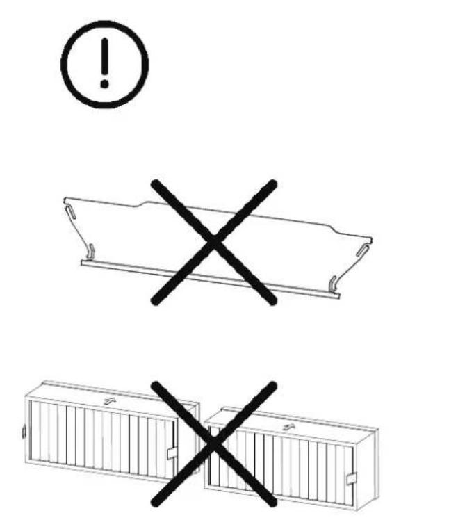
The following overview shows the components of the appliance that you either replace or clean.
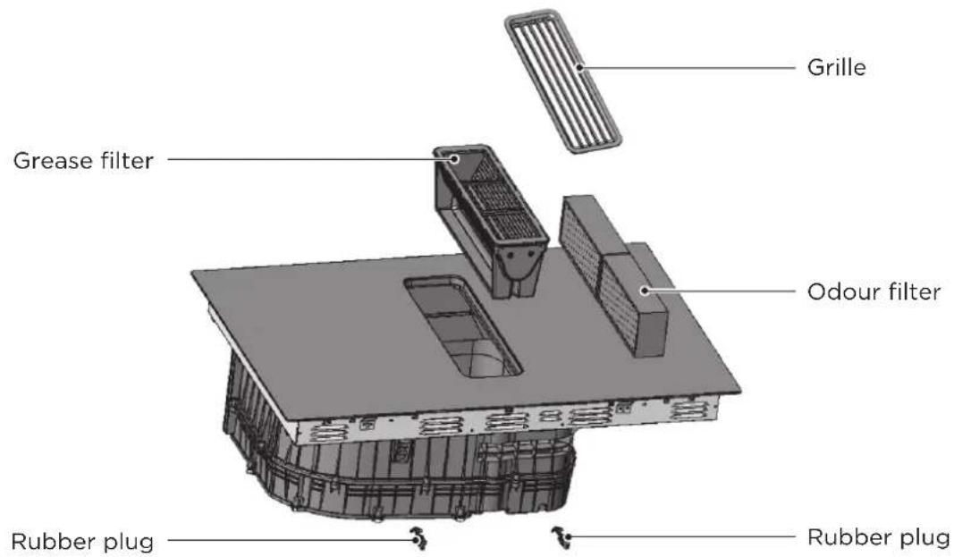
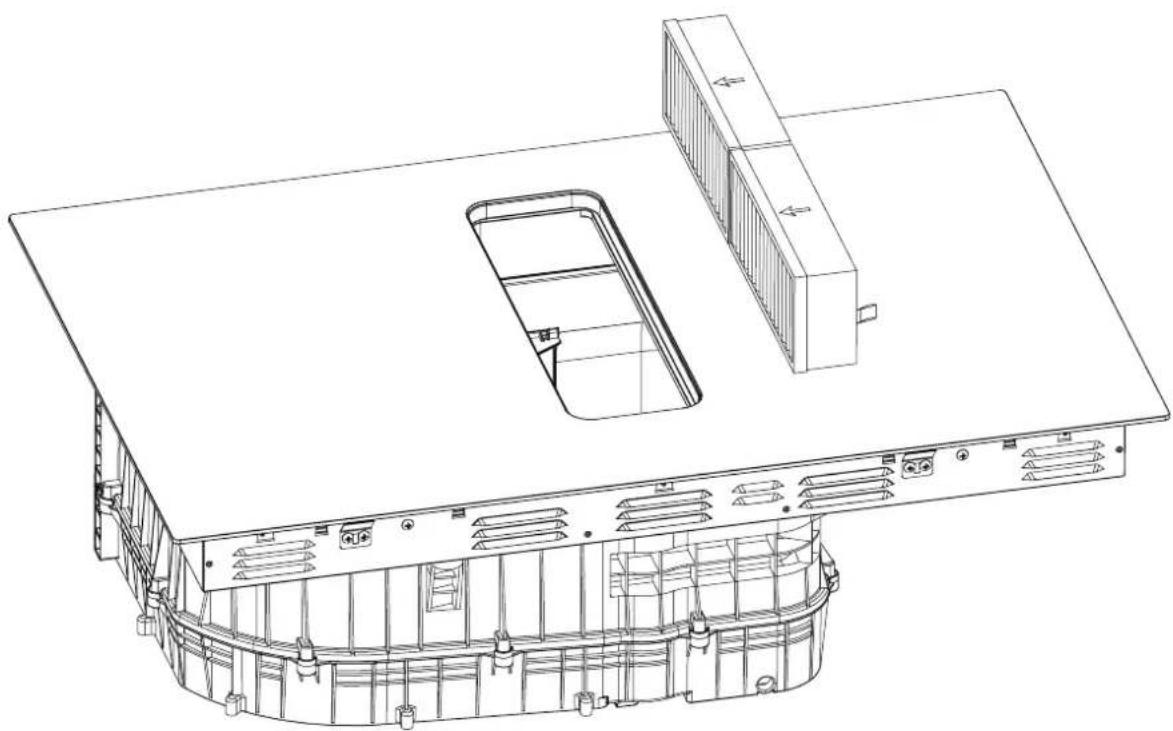
Changing The Odour Filter
Change the odour filter regularly.

NOTE
- You can obtain odour filters from specialist retailers or customer service.
- To keep them in good working order, only use genuine replacement filters.
- ATTENTION!
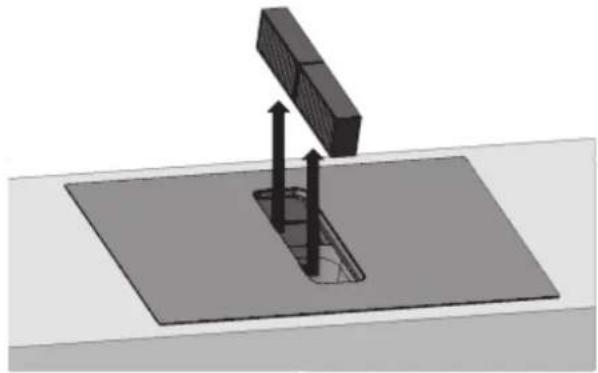
Falling grease filters and grille may damage the hob below.
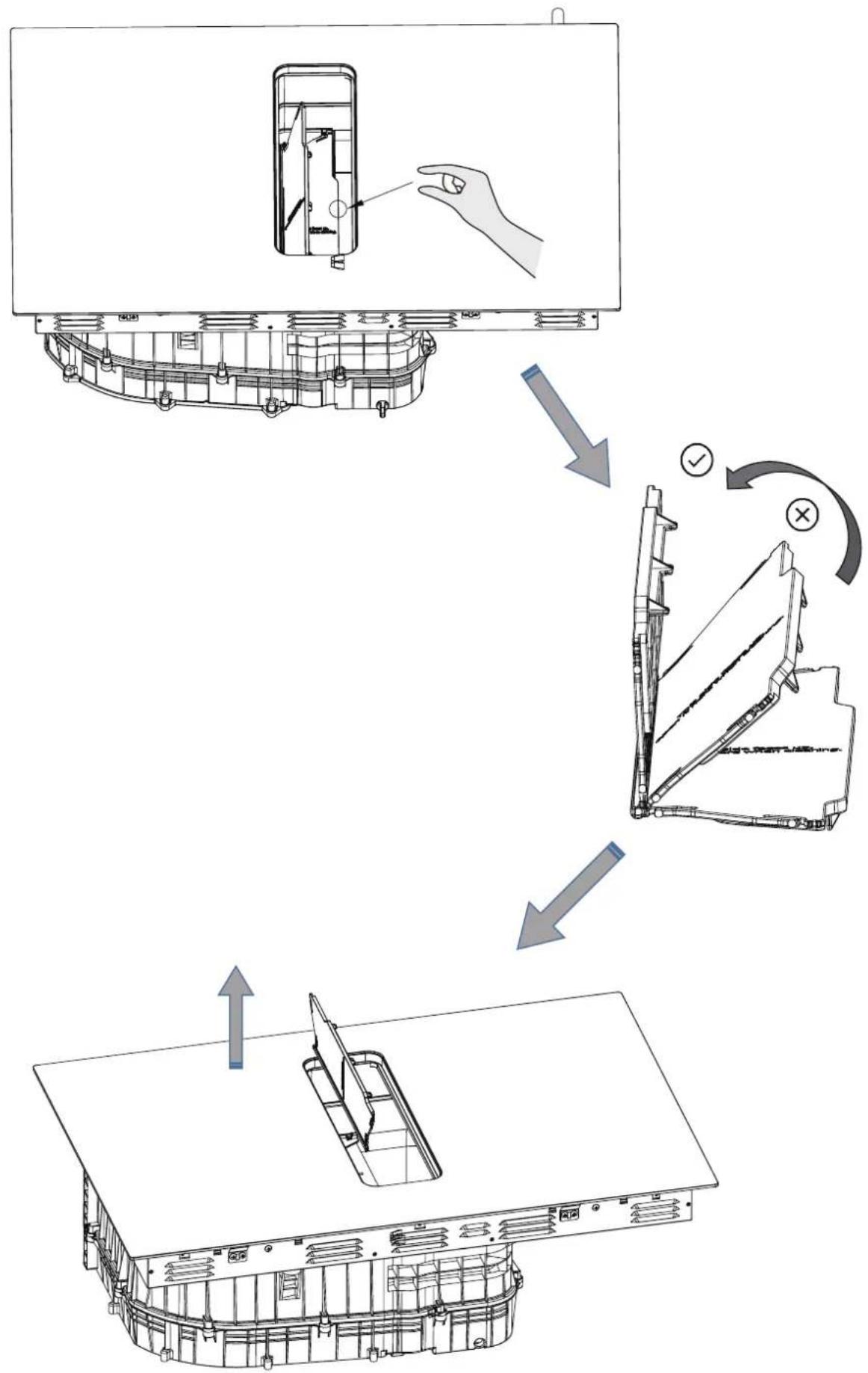
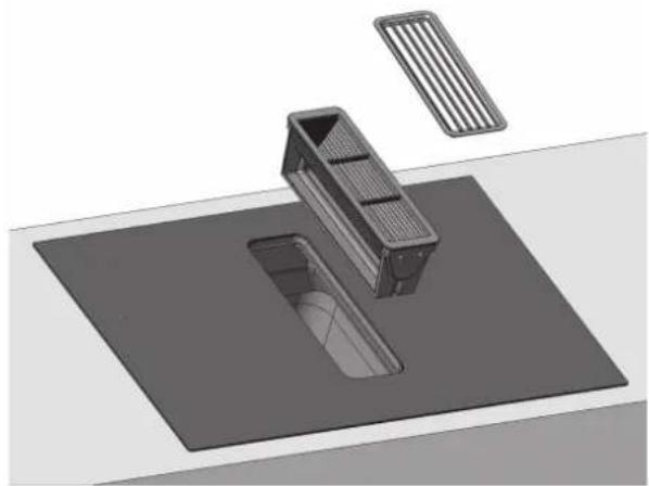
Remove the grille and the grease filter, and dispose of them properly.
- Grease may accumulate in the bottom of the container. Hold the grease filter level to prevent grease from dripping out.
natural_image
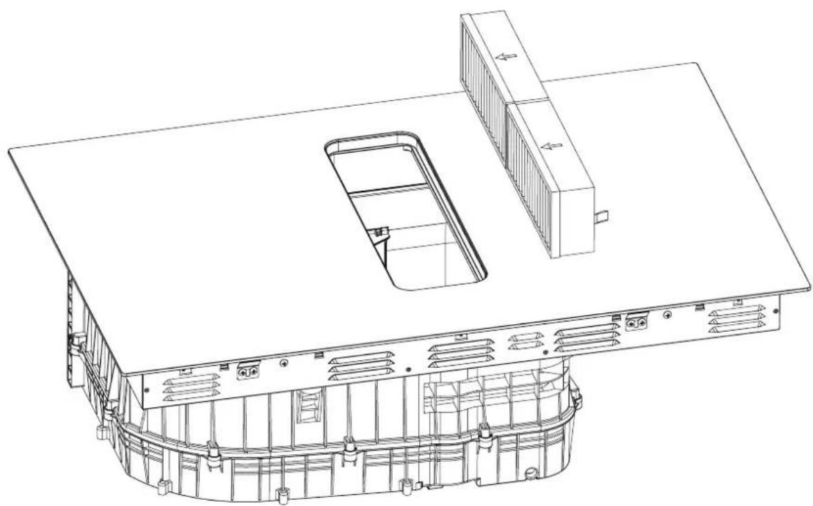
3D rendering of a mechanical component with a rectangular housing and a slatted plate, no visible text or symbols- Remove the two odour filters, and dispose of them properly.
natural_image
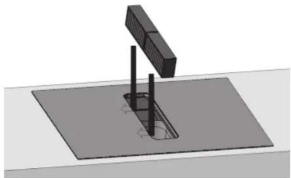
3D diagram of a mechanical assembly with a block and support structure (no text or symbols)- Insert two odour filters into the left of the appliance.
natural_image
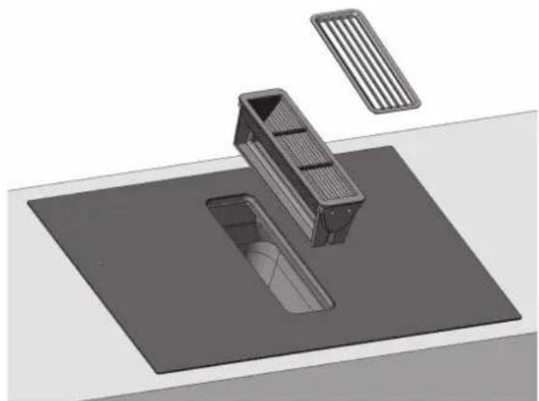
3D diagram of a mechanical assembly with a block and cylindrical components mounted on a flat base (no text or symbols)- Insert the grease filter, and Cover the grille.
natural_image
3D rendering of a mechanical assembly with a rectangular component and a flat base (no text or symbols visible)Resetting the saturation indicator
- Replace the odour filter.
- In the off state, long press lock key 3s to enter lock state.
- long press ✿ key for 3 sec to reset the odour filters, and the hood display screen show "CL"
Cleaning The Grille And Grease Filters
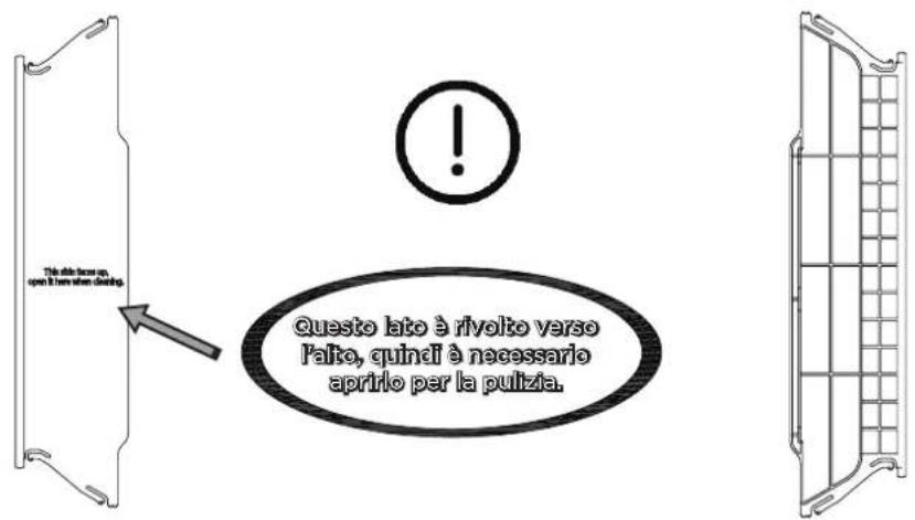
The grease filters filter the grease from the cooking vapour. To keep it in good working order, you must clean the grease filter regularly.
WARNING...Risk of fire!
Fatty deposits in the grease filters may catch fire.
- Never operate the appliance without a grease filter.
- Clean the grease filters regularly.
- Never work with naked flames close to the appli-ance (e.g. flambéing).
- Do not install the appliance near a solid fuel heating appliance (e.g. wood- or coal-burning) unless the heating appliance has a sealed, non-removable cover. There must be no flying sparks.
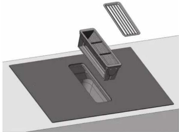
1. ATTENTION!
Falling grease filters may damage the hob below. (It is recommended to clear the grease filter every 7 days)
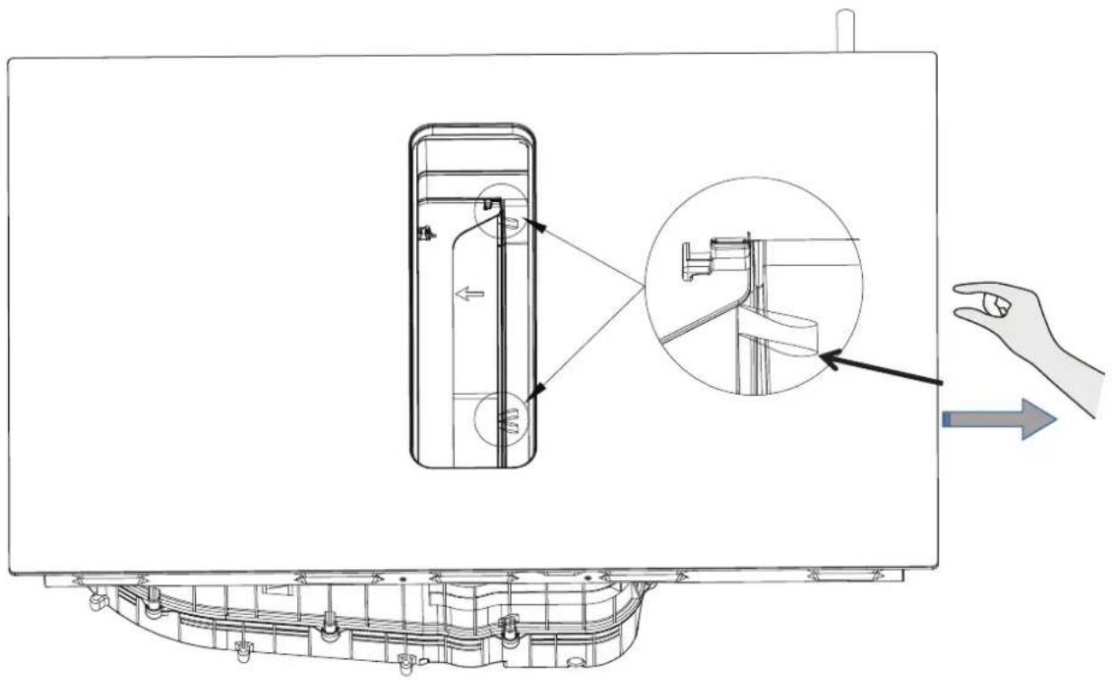
Remove the grille and the grease filter, and dispose of them properly.
- Grease may accumulate in the bottom of the container. Hold the grease filter level to prevent grease from dripping out.
natural_image
3D rendering of a mechanical component with a rectangular housing and a flat base, no visible text or symbols-
Clean the grille.
-
See chapter "Cleaning the grease filters or grille manually"
- Clean the grease filters.
• See chapter "Cleaning the grease filters or grille manually" - See chapter "Cleaning the grease filter in the dishwasher"
- If required, remove the odour filters or acoustics filters and clean the appliance from the inside.
• See chapter "Changing the odour filter" - If any objects get into the appliance, remove these objects and ensure that the supply to the overflowcontainer is not blocked.
- Wipe out the inside of the appliance with soapy water and a dish cloth.
- After cleaning, reinsert the dried metal grease filter.
Cleaning the grease filters or grille manually
- Soak the grease filter or grille in hot soapy water.
- Use a brush to clean the grease filter or grille.
Do not use aggressive, acidic or alkaline cleaning products.
Use special grease solvent for stubborn dirt. - Rinse the grease filters thoroughly.
- Allow the grease filters to drain.
Cleaning the grease filter in the dishwasher
- Place the grease filters loosely in the dishwasher and do not jam it in.
For optimum cleaning results, lay the grease filter on the filter side in the dishwasher.
Do not clean heavily soiled grease filters with utensils.
Do not use aggressive, acidic or alkaline cleaning products. - Start the dishwasher.
Select a temperature of no more than 70^ C. - Allow the grease filters to drain.
Clean The Cavity And Sewage
From the rubber plug, drain liquids or objects that come into the appliance from above.
Requirement: The appliance has cooled and the resid-ual heat indicator has gone out.
- Pull out the rubber plug with one hand and Hold the bin with the other hand, drain liquids or objects from the rubber plug
- Ensure that the supply to rubber plug is not blocked, before plugging it back into place.
Remove any objects that have entered the appliance once it has cooled down. To do this, remove the grease filter.
TROUBLESHOOTING
Operation of your appliance can lead to errors and malfunctions. The following tables contain possible causes and notes for resolving an error message or malfunction. It is recommended to read the tables carefully below in order to save your time and money that may cost for calling to the service center.
| Problem Possible causes What to do! | ||
| The cooktop cannot Be turned on. | No power. | Make sure the ceramic hob is connected to the power supply and that it is switched on. Check whether there is a power outage in your home or area. If you've checked everything and the problem persists, call a qualified technician. |
| The touch controls are unresponsive. | The controls are locked. | Unlock the controls. See section 'Using your ceramic cooktop' for instructions. |
| The touch controls are difficult to operate. | There may be a slight film of water over the controls or you may be using the tip of your finger when touching the controls. | Make sure the touch control area is dry and use the ball of your finger when touching the controls. |
| The glass is being scratched. | Rough-edged cookware.Unsuitable, abrasive scourer or cleaning products being used. | Use cookware with flat and smooth bases. See 'Choosing the right cookware'.See 'Care and cleaning'. |
| Some pans make crackling or clicking noises. | This may be caused by the construction of your cookware (layers of different metals vibrating differently). | This is normal for cookware and does not indicate a fault. |
| The induction hob makes a low humming noise when used on a high heat setting. | This is caused by the technology of induction cooking. | This is normal, but the noise should quieten down or disappear completely when you decrease the heat setting. |
| Fan noise coming from the induction hob. | A cooling fan built into your induction hob has come on to prevent the electronics from overheating. It may continue to run even after you've turned the induction hob off. | This is normal and needs no action. Do not switch the power to the induction hob off at the wall while the fan is running. |
| Pans do not become hot and appears in the display. | The induction hob cannot detect the pan because it is not suitable for induction cooking.The induction hob cannot detect the pan because it is too small for the cooking zone or not properly centred on it. | Use cookware suitable for induction cooking.See section 'Choosing the right cookware'.Centre the pan and make sure that its base matches the size of the cooking zone. |
| The induction hob or a cooking zone has turned itself off unexpectedly, a tone sounds and an error code is displayed (typically alternating with one or two digits in the cooking timer display). | Technical fault. | Please note down the error letters and numbers, switch the power to the induction hob off at the wall, and contact a qualified technician. |
The induction hob is equipped with a self diagnostic function. With this test the technician is able to check the function of several components without disassembling or dismounting the hob from the working surface.
| Problem Possible causes What to do! | ||
| E1,E2,E7 | Please contact the supplier.Temperature sensor failure. | |
| E3,E4 | Temperature sensor of the IGBT failure. | Please contact the supplier. |
| EU | The connection between the display board and the main board is fail. | Please contact the supplier. |
| EL,EH | Abnormal supply voltage | Please inspect whether power supply is normal.Power on after the power supply is normal. |
| C1 | Temperature sensor of the ceramic glass plate Is high. | Please restart after the induction hob cools down. |
| C2 | Temperature sensor of the IGBT Is high | Please restart after the induction hob cools down. |
| F5 | Cooling fan failure | Please restart after the induction hob cools down. |
| B3 | Abnormal temperature in ventilation system | Please restart after the induction motor cools down. |
| B5 | Startup of the Ventilation system fails | Check hood for foreign objects,and restart hood. |
| B7 | Startup of the Ventilation system fails | Please contact the supplier. |
| Bd | The communication between the display board and the hood driver board fails | Please contact the supplier. |
| EF | Multiple function key are pressed at the same time | Clean the operation panel. |
| FC | Filter replacement tips | Please replace the filter screen, refer to the filter screen replacement guide. |
Failure code occur during customer using & Solution;
| Failure code Problem | Solution | |
| Auto-Recovery | ||
| EL,EH | Supply voltage is above the rated voltage. | Please inspect whether power supply is normal.Power on after the power supply is normal. |
| C1 | High temperature of ceramic plate sensor. | Wait for the temperature of ceramic plate return to normal.Touch “ON/OFF” button to restart unit. |
| High temperature of IGBT C2 | Wait for the temperature of IGBT return to normal.Touch “ON/OFF” button to restart unit.Check whether the fan runs smoothly; if not , replace the fan. | |
| B3 | The current of the hood driver board is abnormal. | Touch “ON/OFF” button to restart unit. |
| B7 | Ventilation system air duct fully blocked. | Touch “ON/OFF” button to restart unit.Check hood for foreign objects,and restart hood. |
No Auto-Recovery
| E2 | Ceramic plate temperature sensor failure--short circuit. | Check the connection or replace the ceramic plate temperature sensor. | |
| E1 | Ceramic plate temperature sensor failure--open circuit. | ||
| E7 | Ceramic plate temperature sensor failure--invalid. | ||
| E4 | Temperature sensor of the IGBT failure - short circuit. | Replace the power board. | |
| E3 | Temperature sensor of the IGBT failure - open circuit. | ||
| Replace the hood driver board or motor.Ventilation syste | |||
| Bd | The communication between the display board and the hood driver board fails. | Replace the hood driver, power board, or display board, and check whether the connecting cable is damaged. | |
| Failure Problem Solution BSolution A | |||
| The LED does not come on when unit is plugged in. | No power supplied. | Check to see if plug is secured tightly in outlet and that outlet is working. | |
| The accessorial power board and the display board connected failure. | Check the connection. | ||
| The accessorial power board is damaged. | Replace the accessorial power board. | ||
| The display board is damaged. | Replace the display board. | ||
| Some buttons can't work, or the LED display is not normal. | The display board is damaged. | Replace the display board. | |
| The Cooking Mode Indicator comes on, but heating does not start. | High temperature of the hob. | Ambient temperature may be too high. Air Intake or Air Vent may be blocked. | |
| There is something wrong with the fan. | Check whether the fan runs smoothly; if not , replace the fan. | ||
| The power board is damaged. | Replace the power board. | ||
| Heating stops suddenly during operation and the display flashes “u”. | Pan Type is wrong. | Use the proper pot (refer to the instruction manual.) | Pan detection circuit is damaged, replace the power board. |
| Pot diameter is too small. | |||
| Cooker has overheated; | Unit is overheated. Wait for temperature to return to normal.Push “ON/OFF” button to restart unit. | ||
| Heating zones of the same side ( Such as the first and the second zone ) would display “u”. | The power board and the display board connected failure; | Check the connection. | |
| The display board of communicate part is damaged. | Replace the display board. | ||
| The Main board is damaged. | Replace the power board. | ||
| Fan motor sounds abnormal. | The fan motor is damaged. | Replace the fan. | |
The above are the judgment and inspection of common failures.
Please do not disassemble the unit by yourself to avoid any dangers and damages to the induction hob.
DISPOSAL AND RECYCLING
Important instructions for environment
Compliance with the WEEE Directive and Disposing of the Waster Product:
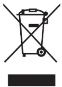
This product complies with EU WEEE Directive (2012/19/EU). This product bears a classification symbol for waster electrical and electronic equipment (WEEE).
This symbol indicates that this product shall not be disposed with other household wastes at the end of its service life. Used device must be returned to official collection point for recycling of electrical electronic devices. To find these collection systems please contact to your local authorities or retailer where the product was purchased. Each household performs important role in recovering and recycling of old appliance.
Appropriate disposal of used appliance helps prevent potential negative consequences for the environment and human health.
natural_image
Symbol of a trash bin crossed with no text or labels, accompanied by a solid black rectangle below (no text or symbols present)Compliance with RoHS Directive
The product you have purchased complies with EU RoHS Directive (2011/65/EU). It does not contain harmful and prohibited materials specified in the Directive.
Package information
Packaging materials of the product are manufactured from recyclable materials in accordance with our National Environment Regulations.
Do not dispose of the packaging materials together with the domestic or other wastes. Take them to the packaging material collection points designated by the local authorities.

natural_image
Recycling symbol with three chasing arrows forming a triangle (no text or labels)
natural_image
Abstract black geometric logo design with stylized 'M' and 'K' shapes (no text or symbols)Master Kitchen
Midea Italia srl
Made in P.R. C.
- Modalità d'uso
- THANK YOU LETTER
- CONTENTS
- SAFETY INSTRUCTIONS
- Intended Use
- Explanation of Symbols
- Safety Warnings
- Installation
- Electrical Shock Hazard
- Cut Hazard
- Important Safety Instructions
- Operation And Maintenance
- Health Hazard
- Hot Surface Hazard
- SPECIFICATIONS
- PRODUCT OVERVIEW
- Top View
- Control Panel
- NOTE
- Working Theory
- Operating Mode
- Air extraction mode
- Air recirculation mode
- Before Using Your New Induction Hob and Hood
- Enter hood mode settings
- QUICK START GUIDE
- Cooking Tips
- Simmering, cooking rice
- Searing steak
- For Stir-frying
- Detection Of Small Articles
- Heat Settings
- PRODUCT INSTALLATION
- Complete Equipment
- Installation Accessories, Outward Discharge
- Installation Accessories, Inward Discharge
- Install Baffle On The Stove
- WARNING: Ensuring Adequate Ventilation
- Before Installing the Hob, Make Sure That
- After Installing the Hob, Make Sure That
- Before Locating the Fixing Brackets
- CAUTIONS
- Connecting the Hob to the Mains Power Supply
- OPERATION INSTRUCTIONS
- Touch Controls
- Choosing the Right Cookware
- How to Use
- Start Cooking
- If the display flashes ÷ alternately with the heat setting
- Manual ventilation control
- Activating the manual ventilation control
- The ventilation system is activated.
- Finish Cooking
- Run-on function for the ventilation system
- Using the Boost function Activate the boost function
- Cancel the Boost function
- Intensive ventilation setting
- Automatic start for the ventilation system
- Flexible Area
- As big zone
- As two independent zones
- Locking the Controls
- To lock the controls
- To unlock the controls
- Power Management Function
- To enter Power Management Function
- To switch to another level
- Confirmation and Exit Power Management Function
- Timer control
- Setting the timer to turn cooking zones off
- Set one zone
- Set more zones:
- Cancel the timer
- Default working times
- CLEANING AND MAINTENANCE
- Components To Be Cleaned Or Replaced
- Changing The Odour Filter
- Cleaning The Grille And Grease Filters
- WARNING...Risk of fire!
- ATTENTION!
- Cleaning the grease filters or grille manually
- Cleaning the grease filter in the dishwasher
- Clean The Cavity And Sewage
- TROUBLESHOOTING
- DISPOSAL AND RECYCLING
- Important instructions for environment
- Compliance with RoHS Directive
- Package information
- Master Kitchen
Brand : Master Kitchen
Model : MKHI 804FH ED BK
Category : Cooker