
CNU-700 - Uncategorized SONY - Free user manual and instructions
Find the device manual for free CNU-700 SONY in PDF.


| Product Type | Camera Command Network Unit |
| Brand | Sony |
| Model | CNU-700 |
| Power Requirements | 100-240 V AC, 50/60 Hz |
| Current Consumption | 4.0 A max (with twelve RCP units and BKP-7930) |
| Dimensions (W x H x D) | 424 x 132 x 400 mm |
| Weight | 9.5 kg |
| Operating Temperature | 5°C to 40°C |
| Storage Temperature | -20°C to +60°C |
| Max Controllable Cameras/Panels | 6 units (12 with optional BKP-7930 board) |
| Control Interfaces | CCU, RCP, MSU, VCS, AUX, RS-232C |
| Reference Signal Input | VS, BS via BNC loopthrough |
| Character Output | 525/625 line black-and-white video, BNC |
| Self-Diagnostic Capability | Yes |
| Emergency Operation | Bypass mode via OPERATION switch |
| Safety Compliance | Class A digital device, FCC Part 15, CE, ICES-003 |
| Supplied Accessories | Operation Manual |
| Optional Accessories | AC power cord, plug retainer, BKP-7930 board |
Frequently Asked Questions - CNU-700 SONY
User questions about CNU-700 SONY
0 question about this device. Answer the ones you know or ask your own.
Ask a new question about this device
Download the instructions for your Uncategorized in PDF format for free! Find your manual CNU-700 - SONY and take your electronic device back in hand. On this page are published all the documents necessary for the use of your device. CNU-700 by SONY.
USER MANUAL CNU-700 SONY
OPERATION MANUAL 1st Edition (Revised 7)
Japanese/English
安全のために
Before operating the software, please read this manual thoroughly and retain it for future reference.
WARNING
To reduce the risk of fire or electric shock, do not expose this apparatus to rain or moisture.
To avoid electrical shock, do not open the cabinet. Refer servicing to qualified personnel only.
THIS APPARATUS MUST BE EARTHED.
For the customers in the U.S.A.
This equipment has been tested and found to comply with the limits for a Class A digital device, pursuant to Part 15 of the FCC Rules. These limits are designed to provide reasonable protection against harmful interference when the equipment is operated in a commercial environment. This equipment generates, uses, and can radiate radio frequency energy and, if not installed and used in accordance with the instruction manual, may cause harmful interference to radio communications. Operation of this equipment in a residential area is likely to cause harmful interference in which case the user will be required to correct the interference at his own expense.
You are cautioned that any changes or modifications not expressly approved in this manual could void your authority to operate this equipment.
All interface cables used to connect peripherals must be shielded in order to comply with the limits for a digital device pursuant to Subpart B of Part 15 of FCC Rules.
This device complies with Part 15 of the FCC Rules. Operation is subject to the following two conditions: (1) this device may not cause harmful interference, and (2) this device must accept any interference received, including interference that may cause undesired operation.

This symbol is intended to alert the user to the presence of important operating and maintenance (servicing) instructions in the literature accompanying the appliance.
WARNING: THIS WARNING IS APPLICABLE FOR USA ONLY.
If used in USA, use the UL LISTED power cord specified below.
DO NOT USE ANY OTHER POWER CORD.
Plug Cap Parallel blade with ground pin (NEMA 5-15P Configuration)
Cord Type SJT, three 16 or 18 AWG wires
Length Minimum 1.5 m (4 ft.11 in.), Less than 2.5 m (8 ft. 3 in.)
Rating Minimum 10 A, 125 V
Using this unit at a voltage other than 120V may require the use of a different line cord or attachment plug, or both. To reduce the risk of fire or electric shock, refer servicing to qualified service personnel.
WARNING: THIS WARNING IS APPLICABLE FOR OTHER COUNTRIES.
-
Use the approved Power Cord (3-core mains lead)/Appliance Connector/Plug with earthing-contacts that conforms to the safety regulations of each country if applicable.
-
Use the Power Cord (3-core mains lead)/Appliance Connector/Plug conforming to the proper ratings (Voltage, Ampere).
If you have questions on the use of the above Power Cord/Appliance Connector/Plug, please consult a qualified service personnel.
For the customers in Canada
This Class A digital apparatus complies with Canadian ICES-003.
For the customers in Europe, Australia and New Zealand
WARNING
This is a Class A product. In a domestic environment, this product may cause radio interference in which case the user may be required to take adequate measures.
For the customers in Europe
This product with the CE marking complies with the EMC Directive issued by the Commission of the European Community.
Compliance with this directive implies conformity to the following European standards:
• EN55103-1: Electromagnetic Interference(Emission)
• EN55103-2: Electromagnetic Susceptibility(Immunity)
This product is intended for use in the following Electromagnetic Environment: E4 (controlled EMC environment, ex. TV studio).
For the customers in Europe
The manufacturer of this product is Sony Corporation, 1-7-1 Konan, Minato-ku, Tokyo, Japan.
The Authorized Representative for EMC and product safety is Sony Deutschland GmbH, Hedelfinger Strasse 61, 70327 Stuttgart, Germany. For any service or guarantee matters please refer to the addresses given in separate service or guarantee documents.
This apparatus shall not be used in the residential area.
For kundene i Norge
Dette utstyret kan kobles til et IT-strømfordelingssystem.
AVERTISSEMENT
Location and Function of Parts and Controls .... 16
Specifications 18
Manuals for the BVP/HDC-series video camera system
Three types of manuals are provided for the BVP/HDC-series video camera system: an Operation Manual, a Maintenance Manual, and a System Manual. The Operation Manual is provided for each device used in the system, and the Maintenance and System Manuals are provided as options.
In the Operation Manual, specific functions and
characteristics of the device, such as features, functions of each part and specifications, are described.
In the Maintenance and System Manuals, you will find general information on the system, such as possible system configurations, the setup method, connections, and system preparations and operations.
Overview
The CNU-700 Camera Command Network Unit is designed for use with a Sony BVP/HDC-series CCD video camera system used in a studio or outdoor broadcast applications. It switches and controls commands used for controlling the video camera system. You can connect multiple CCU/HDCU-series Camera Control Units (each with a BVP/HDC-series Color Video Camera connected), RCP-series Remote Control Panels, and an MSU-900/1000 Master Setup Unit to the CNU-700, which allows you to control any video camera using any remote control panel. The CNU-700 has the following features.
Flexibility of system configuration and high-speed processing
You can control the video cameras and control panels connected to the CNU-700 in any of the three combinations listed below. The CNU-700 allows you to specify which remote control panel controls which video camera so you can easily specify the combination of camera and control panel to be controlled after installation and connection of devices.
•1-on-1 control
One remote control panel or master setup unit controls one video camera.
•N-on-1 control
Two or more remote control panels and a master setup unit control one video camera.
•1-on-N control
One master setup unit controls two or more video cameras.
External control
The CNU-700 has an RS-232C interface for control from external equipment.
Wide extendibility
A single CNU-700 can control up to six video cameras and remote control panels. When you install an optional BKP-7930 CNU IF board in the CNU-700, you can configure a system using up to 12 video cameras and remote control panels. You can connect up to two CNU-700s each other so that up to 24 video cameras and remote control panels are controllable in a system.
Self-diagnostic capability
The CNU-700 outputs the results of self-diagnostics for equipment connected to the CNU-700, such as a video camera.
Emergency correspondence
If an irregularity in the operation of the equipment occurs, the remote control panel can directly control the video camera. When you set the OPERATION switch on the internal board to EMERGENCY, the signals from the remote control panel bypass the CNU-700 and go directly to the video camera connected to the connector of the same number as the remote control panel to continue operations.
Location and Function of Parts and Controls
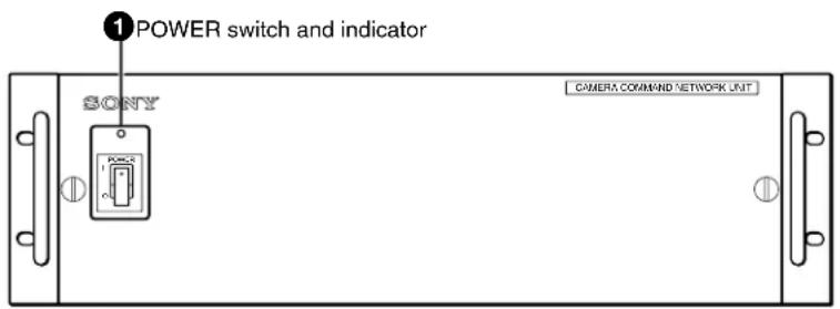
Front panel
Rear panel
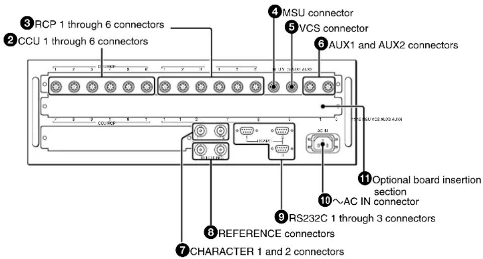
①POWER switch and indicator
Press to turn the power ON or OFF. The indicator lights when power is supplied.
②CCU (camera control unit) 1 through 6 connectors (8-pin)
Connect to the RCP/CNU REMOTE connector on a CCU/HDCU-series Camera Control Unit using a CCA-5 cable.
③RCP (remote control panel) 1 through 6 connectors (8-pin)
Connect to the CCU/CNU REMOTE connectors on an RCP-series Remote Control Panel using a CCA-5 cable.
④MSU (master setup unit) connector (8-pin)
Connect to the CCU/CNU REMOTE connector on an MSU-900/1000 Master Setup Unit using a CCA-5 cable.
⑤VCS (video selector) connector (8-pin)
Connect to the REMOTE connector of a VCS-700 Video Selector using a CCA-5 cable.
⑥ AUX1 and AUX2 (auxiliary 1 and 2) connectors (8-pin)
Connect to the AUX1 or AUX2 connector of another CNU-700 using a CCA-5 cable when controlling multiple cameras with two CNU-700s.
⑦ CHARACTER 1 and 2 connectors (BNC type)
Supply character data as a 525- or 625-line, black-and-white video signal.
The signal to be output is automatically selected according to the reference signal input to the REFERENCE connector. If no reference signal is input, the CNU-700 for the USA and Canada supplies a 525-line video signal, and the CNU-700 for other countries supplies a 625-line video signal. You can select whether to add a sync signal to the output signal with the switch (SYNC ON/OFF) on the AT board.
Refer to the System Manual for details on the board switch settings.
⑧REFERENCE (reference signal input) connectors (BNC type)
Accept a reference signal (VS, BS, etc.). The signal output from the CHARACTER connector is synchronized with the input signal.
⑨RS232C 1 through 3 connectors (D-sub 9-pin)
Used for the RS-232C interface. The function of these connectors depends on whether or not an optional BKP-7930 board is installed in the CNU-700 as shown below.
| Connector No. not | With BKP-7930 With installed installed | BKP-7930 |
| 1 Reserved for ISR system | ||
| 2 Reserved for RS232C interface | ||
| 3 Not used | Reserved for RS232C interface | |
10\~ AC IN (AC power input) connector
Connect to an AC power source using the AC power cord (optional). The power cord can be fixed to the CNU-700 using the plug retainer (optional).
⑪ Optional board insertion section
For attaching the connector panel of an optional BKP-7930. When you attach the BKP-7930 to the CNU-700, it can control up to 12 video cameras and remote control panels.
Specifications
General
Power requirements 100 to 240 V AC, 50/60 Hz
Current consumption When connecting twelve RCP-series units using a BKP-7930: 4.0 A max.
Peak inrush current
(1)Power ON, current probe method: 10 A (100 V), 70 A (240V)
(2) Hot switching inrush current, measured in accordance with European standard EN55103-1: 14 A (230 V)
Operating temperature
5^ to 40^ (41^ to 104^)
Storage temperature
-20^ to +60^ (-4^ to +140^
Dimensions 424 × 132 × 400 mm (w/h/d) (16^3/4 × 5^1/4 × 15^3/_4 inches)
Mass 9.5 kg (20 lb 15 oz)
Input and output connectors
CCU 1 through 6 8-pin multiconnector (1 each)
RCP 1 through 6 8-pin multiconnector (1 each)
MSU 8-pin multiconnector (1)
VCS 8-pin multiconnector (1)
AUX 1 and 2 8-pin multiconnector (1 each)
CHARACTER BNC type (2) video: 0.7 Vp-p, sync: 0.3 Vp-p
REFERENCE BNC type (2) 0.3 Vp-p with loopthrough output
RS232C D-sub 9-pin (3)
AC IN 3-pin (1)
Supplied accessories
Operation Manual (1)
Optional accessories
AC power cord
- For customers in the USA and Canada Power cord (125 V, 10 A, 2.4 m (8 feet)) (Part No. 1-551-812-1X)
Plug retainer (Part No. 2-990-242-0X)
- For customers in the European countries Power cord (250 V, 10 A, 2.5 m (8.3 feet)) (Part No. 1-782-929-1X) Plug retainer (Part No. 2-990-242-0X)
Design and specifications are subject to change without notice.
Note
Always verify that the unit is operating properly before use. SONY WILL NOT BE LIABLE FOR DAMAGES OF ANY KIND INCLUDING, BUT NOT LIMITED TO, COMPENSATION OR REIMBURSEMENT ON ACCOUNT OF THE LOSS OF PRESENT OR PROSPECTIVE PROFITS DUE TO FAILURE OF THIS UNIT, EITHER DURING THE WARRANTY PERIOD OR AFTER EXPIRATION OF THE WARRANTY, OR FOR ANY OTHER REASON WHATSOEVER.
The material contained in this manual consists of information that is the property of Sony Corporation and is intended solely for use by the purchasers of the equipment described in this manual.
Sony Corporation expressly prohibits the duplication of any portion of this manual or the use thereof for any purpose other than the operation or maintenance of the equipment described in this manual without the express written permission of Sony Corporation.
For Customer in China
- 安全のために
- WARNING
- THIS APPARATUS MUST BE EARTHED.
- For the customers in the U.S.A.
- WARNING: THIS WARNING IS APPLICABLE FOR USA ONLY.
- WARNING: THIS WARNING IS APPLICABLE FOR OTHER COUNTRIES.
- For the customers in Canada
- For the customers in Europe, Australia and New Zealand
- For the customers in Europe
- For kundene i Norge
- AVERTISSEMENT
- Manuals for the BVP/HDC-series video camera system
- Overview
- Flexibility of system configuration and high-speed processing
- •1-on-1 control
- •N-on-1 control
- •1-on-N control
- External control
- Wide extendibility
- Self-diagnostic capability
- Emergency correspondence
- Location and Function of Parts and Controls
- ①POWER switch and indicator
- ②CCU (camera control unit) 1 through 6 connectors (8-pin)
- ③RCP (remote control panel) 1 through 6 connectors (8-pin)
- ④MSU (master setup unit) connector (8-pin)
- ⑤VCS (video selector) connector (8-pin)
- ⑥ AUX1 and AUX2 (auxiliary 1 and 2) connectors (8-pin)
- ⑦ CHARACTER 1 and 2 connectors (BNC type)
- ⑧REFERENCE (reference signal input) connectors (BNC type)
- ⑨RS232C 1 through 3 connectors (D-sub 9-pin)
- 10\~ AC IN (AC power input) connector
- ⑪ Optional board insertion section
- Specifications
- General
- Input and output connectors
- Supplied accessories
- Optional accessories
- Note
Brand : SONY
Model : CNU-700
Category : Uncategorized