
FWUI5152G - Wine cellar VIKING - Free user manual and instructions
Find the device manual for free FWUI5152G VIKING in PDF.


| Product Type | Wine Cellar (Undercounter) |
| Model | FWUI5152G |
| Brand | Viking |
| Capacity | 24 bottles (6 shelves × 4 bottles) |
| Shelf Configuration | 6 adjustable wire racks |
| Interior Light | LED, adjustable color (white/blue) and intensity |
| Door Style | Reversible; compatible with custom integrated panels |
| Dimensions (Width) | 15" (38.1 cm) |
| Dimensions (Height) | 33 3/4" to 34 3/4" (85.7 – 88.3 cm) adjustable |
| Dimensions (Depth) | 22 7/8" (58.1 cm) |
| Weight | 105 lbs (47.6 kg) |
| Electrical Requirements | 115 V, 60 Hz, 15 A dedicated circuit |
| Refrigerant | R600a (Isobutane) |
| Temperature Control | Electronic touch controls with actual temperature display |
| Special Modes | Sabbath mode, door open alert, high/low temperature alarms |
| Warranty | 2 years full; 6 years sealed system; 12 years limited on sealed system |
| Installation | Built-in/undercounter; requires front grille ventilation |
| Safety Features | Anti-tip bracket, child safety warnings |
| Care and Cleaning | Mild soap and water; avoid abrasive cleaners; disconnect power before cleaning |
| Service Information | Contact authorized service; need model/serial number; (888) 845-4641 |
Frequently Asked Questions - FWUI5152G VIKING
User questions about FWUI5152G VIKING
0 question about this device. Answer the ones you know or ask your own.
Ask a new question about this device
Download the instructions for your Wine cellar in PDF format for free! Find your manual FWUI5152G - VIKING and take your electronic device back in hand. On this page are published all the documents necessary for the use of your device. FWUI5152G by VIKING.
USER MANUAL FWUI5152G VIKING
Install / Use & Care
MANUAL

Professional Undercounter Wine Cellars
FWUI5152G
CONTENTS
Contents:
Important Safety Instructions ....2
Unpacking Your Appliance 3
Installing Your Appliance 4
Door Reversal 6
Product Dimensions 7
Installing the Anti-Tip Device 9
Integrated Panel Dimensions ......11
Integrated Panel Installation 12
Using Your Electronic Control 16
Interior Adjustments 17
Shelving Configurations ......18
Care and Cleaning 19
Energy Saving Tips 19
Service Information......20
Troubleshooting 21
Warranty 22
Important Safety Instructions
Warnings and safety instructions appearing in this guide are not meant to cover all possible conditions and situations that may occur. Common sense, caution, and care must be exercised when installing, maintaining, or operating this appliance.
Recognize Safety Symbols, Words, and Labels.

WARNING
WARNING - You can be killed or seriously injured if you do not follow these instructions.

CAUTION
CAUTION-Hazards or unsafe practices which could result in personal injury or property / product damage.
NOTE
NOTE-Important information to help assure a problem free installation and operation.

WARNING
State of California Proposition 65 Warning:
This product contains one or more chemicals known to the State of California to cause cancer.

WARNING
State of California Proposition 65 Warning: This product contains one or more chemicals known to the State of California to cause birth defects or other reproductive harm..

WARNING
WARNING - This unit contains R600a (Isobutane) which is a flammable hydrocarbon. It is safe for regular use. Do not use sharp objects to expedite defrosting. Do not damage refrigerant circuit.

WARNING
EXCESSIVE WEIGHT HAZARD
Use two or more people to move product. Failure to do so can result in personal injury.
Remove Interior Packaging
Your appliance has been packed for shipment with all parts that could be damaged by movement securely fastened. Remove internal packing materials and any tape holding internal components in place. The owners manual is shipped inside the product in a plastic bag along with the warranty registration card, and other accessory items.
Important
Keep your carton and packaging until your appliance has been thoroughly inspected and found to be in good condition. If there is damage, the packaging will be needed as proof of damage in transit. Afterwards please dispose of all items responsibly.

WARNING
WARNING - Dispose of the plastic bags which can be a suffocation hazard.
Note to Customer
This merchandise was carefully packed and thoroughly inspected before leaving our plant. Responsibility for its safe delivery was assumed by the retailer upon acceptance of the shipment. Claims for loss or damage sustained in transit must be made to the retailer.
NOTE
DO NOT RETURN DAMAGED MERCHANDISE TO THE MANUFACTURER - FILE THE CLAIM WITH THE RETAILER.

CAUTION
If the appliance was shipped, handled, or stored in other than an upright position for any period of time, allow the appliance to sit upright for a period of at least 24 hours before plugging in. This will assure oil returns to the compressor. Plugging the appliance in immediately may cause damage to internal parts.
Warranty Registration
It is important you send in your warranty registration card immediately after taking delivery of your appliance or you can register online at www.vikingrange.com.
The following information will be required when registering your appliance.
Service Number
Serial Number
Date of Purchase
Dealer's name and address
Online registration available at
www.vikingrange.com
The service number and serial number can be found on the serial plate which is located inside the cabinet on the left side near the top. See figure 1.
VIKING RANGE, LLC
GREENWOOD, MS 38930
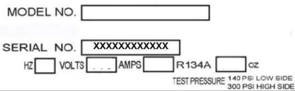
Figure 1

WARNING
WARNING - Help Prevent Tragedies
Child entrapment and suffocation are not problems of the past. Junked or abandoned refrigerators are still dangerous - even if they sit out for "just a few hours".
If you are getting rid of your old refrigerator, please follow the instructions below to help prevent accidents.
Before you throw away your old refrigerator or freezer:
• Take off the doors or remove the drawers.
- Leave the shelves in place so children may not easily climb inside.
Select Location
The proper location will ensure peak performance of your appliance. We recommend a location where the unit will be out of direct sunlight and away from heat sources. To ensure your product performs to specifications, the recommended installation location temperature range is from 55 to 100°F (13 to 38°C).
Cabinet Clearance
Ventilation is required from the bottom front of the appliance. Keep this area open and clear of any obstructions. Adjacent cabinets and counter top can be installed around the appliance as long as the front grille remains unobstructed. All Professional models with articulated hinges are intended for built-in applications only.

CAUTION
Front Grille
Do not obstruct the front grille. The openings within the front grille allow air to flow through the condenser heat exchanger. Restrictions to this air flow will result in increased energy usage and loss of cooling capacity. For this reason it is important this area to not be obstructed and the grille openings kept clean. Viking Range, LLC does not recommend the use of a custom made grille as air flow may be restricted. (See Figure 2).
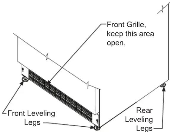
Figure 2
Leveling Legs
Adjustable legs at the front and rear corners of the appliance should be set so the unit is firmly positioned on the floor and level from side to side and front to back. The overall height of your appliance may be adjusted higher (by turning the leveling leg out, CCW) and lower (by turning the leveling leg in, CW) dimensions as shown in Table "A".
To adjust the leveling legs, place the appliance on a solid surface and protect the floor beneath the legs to avoid scratching the floor. With the assistance of another person, lean the appliance back to access the front leveling legs. Raise or lower the legs to the required dimension by turning the legs. Repeat this process for the rear by tilting the appliance forward using caution. On a level surface check the appliance for levelness and adjust accordingly.
The front grille screws may be loosened and the grille adjusted to the desired height. When adjustment is complete tighten the two front grille screws. (See Figure 5).
| Model | Door Style | Minimum Height | Maximum Height |
| FWUI5152 | (G) | 33 3/4"(85.7 cm) | 34 3/4"(88.3 cm) |
Table A
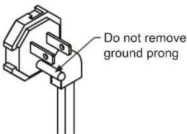
Figure 3
natural_image
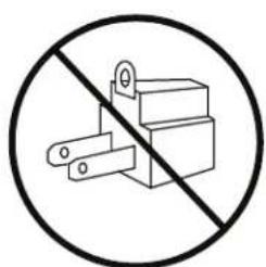
Prohibition sign showing a crossed-out electrical component with no text or symbolsFigure 4
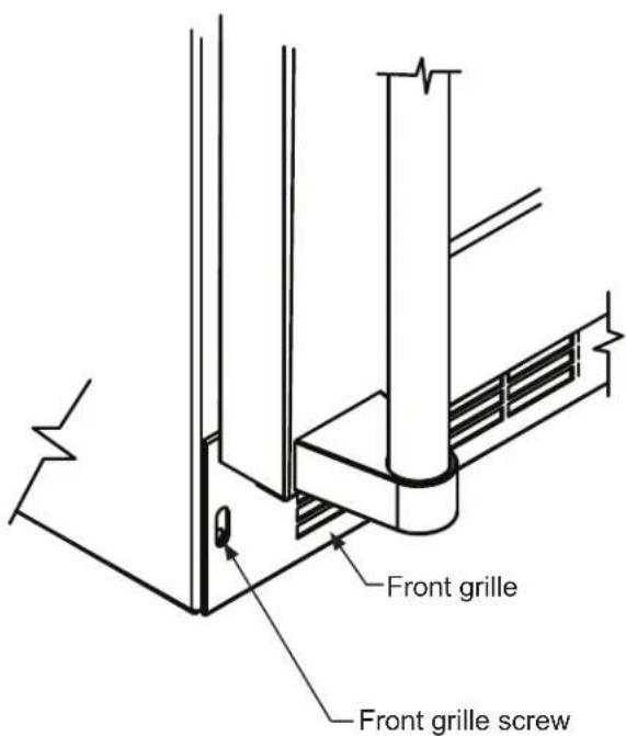
Figure 5

WARNING
Electrical Shock Hazard
- Do not use an extension cord with this appliance. They can be hazardous and can degrade product performance.
- This appliance should not, under any circumstances, be installed to an un-grounded electrical supply.
- Do not remove the grounding prong from the power cord. (See Figure 3).
- Do not use an adapter. (See Figure 4).
- Do not splash or spray water from a hose on the appliance. Doing so may cause an electrical shock, which may result in severe injury or death.
Electrical Connection
A grounded 115 volt, 15 amp dedicated circuit is required.
This product is factory equipped with a power supply cord that has a three-pronged, grounded plug. It must be plugged into a mating grounding type receptacle in accordance with the National Electrical Code and applicable local codes and ordinances (see Figure 6). If the circuit does not have a grounding type receptacle, it is the responsibility and obligation of the customer to provide the proper power supply. The third ground prong should not, under any circumstances, be cut or removed.

natural_image
Electrical outlet diagram showing two socket plugs connected to a terminal block (no text or symbols)Figure 6
NOTE
Ground Fault Circuit Interrupters (GFCI) are prone to nuisance tripping which will cause the appliance to shut down. GFCI's are generally not used on circuits with power equipment that must run unattended for long periods of time, unless required to meet local building codes and ordinances.
DOOR REVERSAL
Door Reversing Instructions
-
Open door.
-
Loosen screw #1 and #2 using a Philips Screwdriver on top and bottom hinge. Slide door and remove the door from the unit.

Figure 7
- Once door is removed, using a Philips Screwdriver remove screws from magnet actuator located on inside and bottom of door. (On Integrated Models magnet actuator will be located on bottom of door.

natural_image
Technical line drawing of a device rear panel with ports and connectors (no text or symbols)Figure 8

natural_image
Technical line drawing of a mechanical assembly with mounting holes and a bracket (no text or symbols)Figure 9
- Remove caps from top of door. Using a Philips Screwdriver, install magnet actuator on opposite side. Install caps into opposite side.
- Remove caps from screw holes on opposite side (2 on top and bottom). Using a Philips Screwdriver remove the 4 screws that you previously loosened.
- Reinstall screws and caps on opposite side.
- Once screws are partially installed, rotate the door 180^ , align the hinge over screw #1 and slide into position. Tighten screws on top and bottom.
- Door is now reversed.
PRODUCT DIMENSIONS
| ROUGH-IN OPENING DIMENSIONS CABINET DIMENSIONS | ||||||||
| “A” “B” | “C” “D” “E” “F” “G” | “H” “J” | ||||||
| 15"(38.1 cm) | 34" to 35"(86.4 cm to 88.9 cm) | 24"(61 cm) | 14 7/8"(37.8 cm) | 33 3/4" to 34 3/4"(85.7 cm to 88.3 cm) | 22 7/8"(58.1 cm) | - | 38 7/8"(98.7 cm) | - |
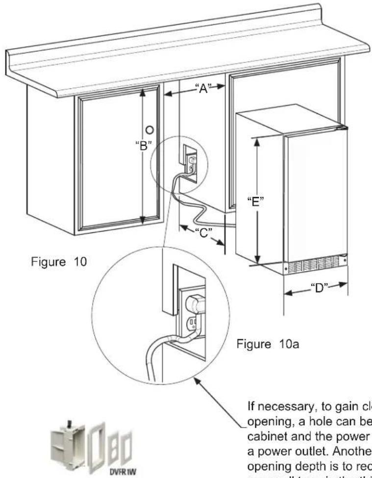
Figure 11
If necessary, to gain clearance inside the rough-in opening, a hole can be cut through the adjacent cabinet and the power cord routed through this hole to a power outlet. Another way to increase the available opening depth is to recess the power outlet into the rear wall to gain the thickness of the power cord plug. Not all recessed outlet boxes will work for this application as they are too narrow, but a recessed outlet box equivalent to Arlington #DVFR1W us recommended for this application (see figure 11).
PRODUCT DIMENSIONS
| PRODUCT DATA | |
| ELECTRICAL REQUITEMENTS # | PRODUCT WEIGHT |
| 115V/60Hz/15A | 105 lbs(47.6 kg) |
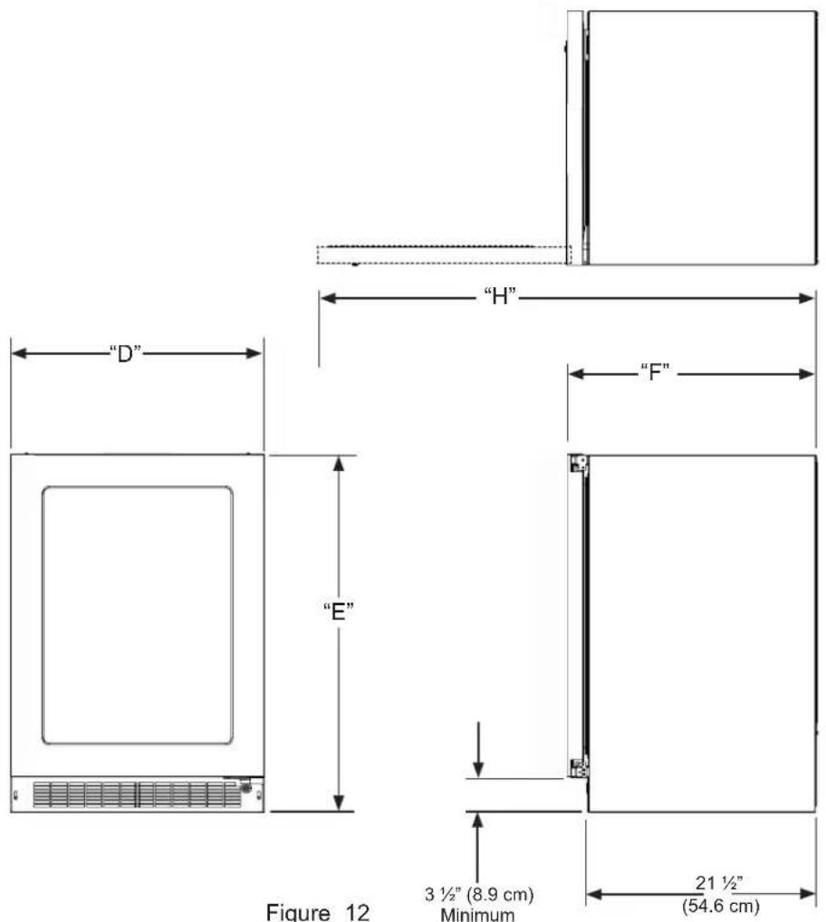
Minimum rough-in opening is required to be larger than the adjusted height of the cabinet.
A grounded 15-amp dedication circuit us required. Follow all local building codes when installing electrical and appliance.

WARNING

• ALL APPLIANCES CAN TIP RESULTING IN INJURY.
• INSTALL THE ANTI-TIP BRACKET PACKED WITH THE APPLIANCE.
• FOLLOW THE INSTRUCTIONS BELOW
Anti-Tip Device

Figure 13

WARNING
If your appliance is not located under a counter top (freestanding), you must use an anti-tip device installed as per these instructions. If the appliance is removed from its location for any reason, make sure that the device is properly engaged with the anti-tip bracket when you push the appliance back into the original location. If the device is not properly engaged, there is a risk of the appliance tipping over, with the potential for property damage or personal injury.
NOTE
If installing on a concrete floor, concrete fasteners are required, (not included with the anti-tip kit).

CAUTION
Any finished flooring should be protected with appropriate material to avoid damage when moving the unit.
Floor Mount Installation
The anti-tip bracket is to be located on the floor in the left or right rear corner of the wine cellar as shown in Figure 13.
Step by step instructions for locating the position of the bracket:
1) Decide where you want to place the appliance. Slide it into place, being careful not to damage the floor, leaving 1" (2.5 cm) of clearance from the rear wall to allow room for the anti-tip bracket.
2) Raise the rear leveling legs approximately/ ^4 (6 mm) to allow engagement with the anti-tip bracket. Level the unit by adjusting all the leveling legs as required. Turning the leveling leg counterclockwise will raise the unit and clockwise will lower the unit.
3) Make sure the appliance is in the desired location, then mark on the floor the rear and side corner of the cabinet where the anti-tip bracket will be installed. If the installation does not allow marking the rear corner of the cabinet, then make temporary lines on the floor marking the front corner of the cabinet, excluding the door. Slide the appliance out of the way. From the temporary line extend the sidewall line back 21½" (54.6 cm) as shown in Figure 14.
4) Align the anti-tip bracket to the marks on the floor so the side of the bracket lines up with the side of the cabinet mark, and the "V" notches on the anti-tip bracket line up with the end of the 21½" (54.6 cm) line (Rear of cabinet line).
5) Fasten the anti-tip bracket to the floor using the supplied screw. (See Figure 14).
6) Slide the cabinet back into position, making sure the rear cabinet leveling leg slides under the anti-tip bracket engaging the slot.
NOTE
When the floor mounted anti-tip bracket is used the minimum adjusted height of the cabinet is increased by 38 " (9 mm).

INTEGRATED PANEL DIMENSIONS
Figure 15
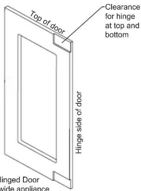
Left Hand Hinged Door 15" (38.1 cm) wide appliance

Figure 16
![3-3/4" [9.5cm] 2" [5.1cm] 3" [7.6cm] 30-7/16" [77.3cm] 2" [5.1cm] 3-3/4" [9.5cm] 4" [10.1cm] 4" [7.6cm] 4" [10.1cm]](/content/2026/05/915326/images/09f45d0e54b87d469e6097b70bd8b9e6a8c0acbd2e03364d90ada18a6b631e10.jpg)
Left Hand Hinged Door 15" (38.1 cm) wide appliance

Figure 17
Right Hand Hinged Door 15" (38.1 cm) wide appliance
![14-3/4" [37.5cm] 1/4' [0.6cm]](/content/2026/05/915326/images/31b5152116a63ffc54eab03c68ac6140e851e69f5d7ae38d8cd57308a96dc5a2.jpg)
Figure 18
![4' [10.1cm] 3-3/4" [9.5cm] 2" [5.1cm] 3" [7.6cm] 30-7/16" [77.3cm] 2" [5.1cm] 4" [10.1cm] 3-3/4" [9.5cm]](/content/2026/05/915326/images/545f2b2c7b02d1dc36fab8b4876d785e5dc54cb7a2202bf64f505e7a1c457023.jpg)
Right Hand Hinged Door 15" (38.1 cm) wide appliance
Integrated door panel installation:
Your unit is equipped with articulated hinges to allow fully integrated built-in installations. Custom panel thicknesses of 5/8" (15 mm) and 3/4" (18 mm) are accommodated.

AUTION
It is important to use the factory provided grille that came with the product to assure proper air flow is maintained through the condenser. The use of a custom grille is not recommended and will void the warranty.

WARNING
Integrated panel models are designed for use with built-in installations only. Use in freestanding installations could result in personal injury.
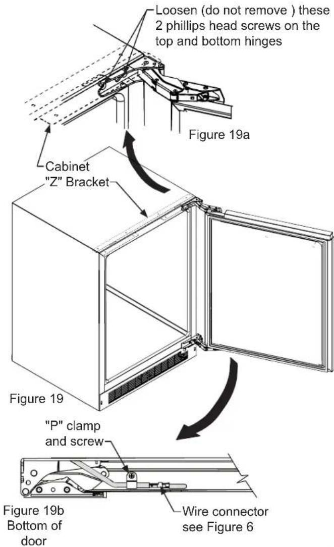
Step 1: Removing the Door
Open the door and loosen the screws holding the hinges to the cabinet (2 at the top and 2 at the bottom hinge). Do not remove the screws but loosen them enough so the hinges can be slipped off of the screws when sliding the door to the side.

WARNING
The articulated hinges have many pinch points. Carefully close / collapse the hinges as soon as the door is removed from the cabinet.
With a helper, and being careful not to scratch the cabinet or the door, slide the door to the side about 12 inch and remove the hinges and door from the unit.

WARNING
Use extreme caution with the articulated hinges. The hinge is self closing and many pinch points exist prior to built-in installation. Do not remove the cabinet "Z" bracket from the top of the cabinet.
Step 2: Remove the door gasket
With the door laying on a flat surface and starting at a corner of the door remove the magnetic door gasket from the interior side of the door, see Figure 21. Set the gasket aside on a flat surface.
There are 10 holes in the gasket retainer extrusions, (3 on each side and 2 at the top and bottom which are used to fasten the panel to the front of the door. The screws are provided in the literature pack along with the door lock, which is provided on certain models.

Step 3: Cut and drill the integrated panel
Depending on your model cut the integrated door panel to the dimensions shown in Figures 15 to 18. The window cut out is for glass door models only. If your appliance has a lock also drill the lock hole in the panel, see Figure 21.

CAUTION
Weight of integrated door panel must not exceed 15 pounds (6.8 kg) for a solid door model or 10 pounds (4.5 kg) for a glass door model.
| Material Type #10 Wood Screw | |
| Hardwood | 12'' (3.2 mm) Diameter. Pilot Hole |
| Softwood | 14'' (2.8 mm) Diameter. Pilot Hole |
Table A
Step 4: Assemble the panel to the door
The preferred method of attaching the panel to the door is to clamp the panel to the door so it cannot move while drilling the screw pilot holes. Use bar clamps or "C" clamps with pads on the clamping surfaces that will not mar the panel or the door. The custom integrated panel should be flush with the top of the door and centered along the width of the door. See Figure 20a. Drill holes through the gasket extrusion using the 10 holes as pilot holes. Use the drill size from the chart in Table "A", being careful not to drill through the front surface of the panel. If the integrated panel is thinner than 58 " (16 mm) thick shorter screws will have to be obtained. Fasten the panel to the door with the 10 screws provided in the literature pack. (See Figure 21a). Remove the clamps and replace the gasket in the gasket extrusion channels of the door. Some force may be required to seat the gasket into the channels. Be sure the gasket corners are seated properly.
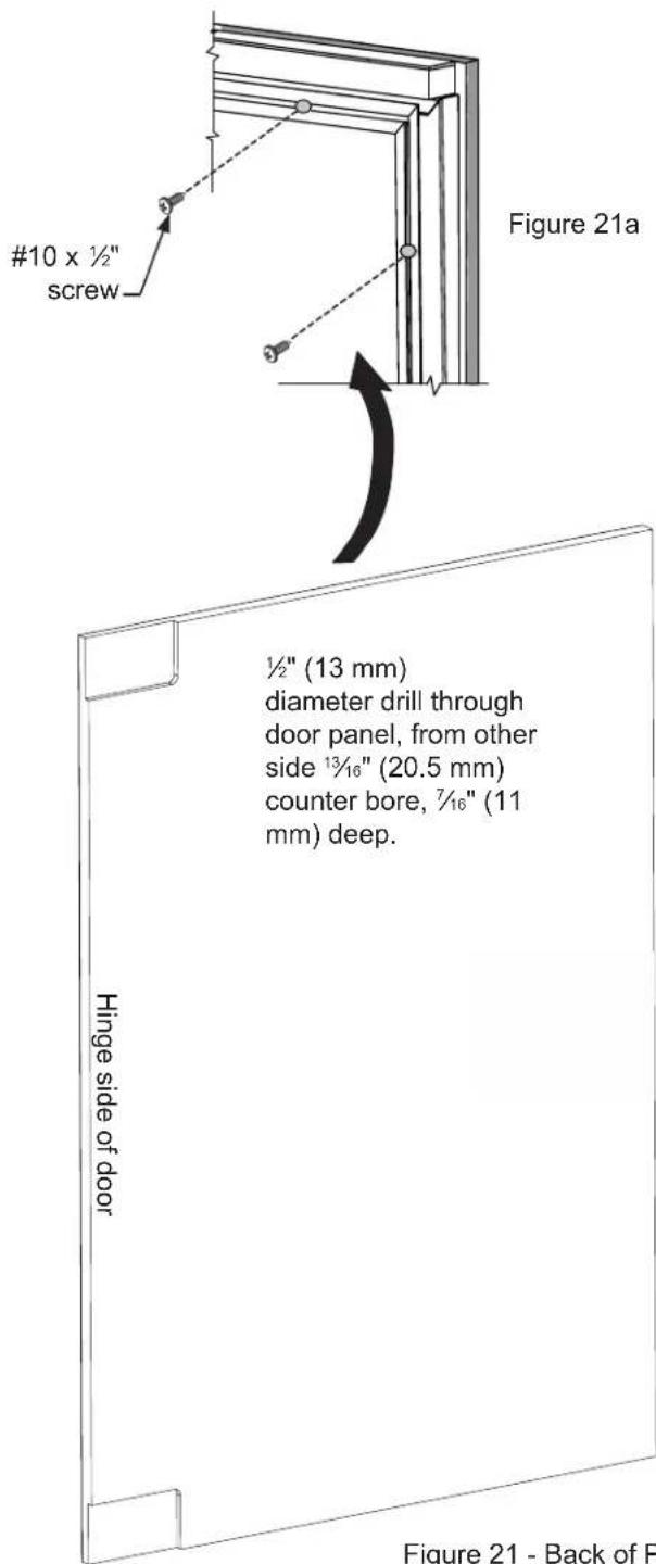
Figure 21 - Back of Panel
INTEGRATED PANEL INSTALLATION
Step 5: Install the door
Carefully open the top and bottom hinges on the door being careful as there are many pinch points. Place the hinges over the 4 screws in the cabinet, 2 at the top and 2 at the bottom and slide the door into position. Tighten the 4 hinge screws with a phillips screwdriver.
Step 6: Secure the cabinet
Use the #8 x 3/4" black screws from the literature pack to secure the counter top to the cabinet top through the holes in the cabinet "Z" bracket.

USING YOUR ELECTRONIC CONTROL




Figure 25
Control Function Guide
| Function Command Notes | ||
| ON/OFF Press and release. | Unit will immediately turn ON or OFF. | |
| Adjust Temperature Press or | and release. | When the display is flashing, pressorto adjust the set point temperature. Note: temperature displayed is the actual temperature inside unit. |
| Toggle Between ^oF / ^oC | Holdandfor 5 seconds. | The display will change units. |
| Leave Interior Light On | Pressand release to leave interior light on for 12 hours; press again to deactivate. | After 12 hours, factory default is restored; light will turn on when door is open. |
| Adjust Light Color | While holding=, press and releaseto scroll through lighting options. | Option Open Door Closed DoorWhite WhiteBlue BlueWhite BlueLight will be set at full intensity when door is open, and 50% intensity when door is closed. |
| Enable Sabbath Mode Press | and hold for 5 seconds and release. | The ^oF / ^oC symbol will flash briefly after 5 seconds. Interior light and display will go dark and remain so until user resets mode - unit continues to operate. |
| Disable Sabbath Mode | Pressand release. | Display and interior light return to normal operation. |
Door Alert Notification
When the door is left open for more than 30 minutes:
• A tone will sound for several seconds every minute
- dr: will appear in display
- Close door to silence alert and reset
High/Low Temp. Notifications
When the compartment temperature exceeds the control setting for an extended amount of time:
• "HH" will appear in display (High Temp)
- "LL" will appear in display (Low Temp)
Contact service dept. for further instructions.
NOTE
Temperature displayed reflects actual temperature inside unit. If the temperature displayed is different than selected, the unit is progressing towards the selected temperature. Time to reach set point varies based upon ambient temperature, temperature of product loaded, door openings, etc. Viking recommends allowing the unit to reach set points before loading.

CAUTION
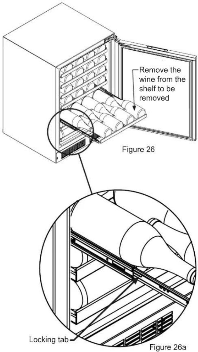
Never try to remove a loaded shelf, remove everything from the shelf before removing. Use both hands when removing the shelf.
To remove a shelf:
Extend the shelf out of the cabinet until it stops.
Unload the shelf (see Figure 26).
Depress the locking tabs on both sides of the shelf and pull the shelf straight out (see Figure 26a). When the shelf is removed, push the extended cabinet mounted shelf extensions back into the cabinet.
To re-install a shelf:
Pull out the cabinet mounted shelf extensions to assist the engagement with the wire rack shelf.
Insert the wire rack side track into the cabinet mounted shelf extensions on both sides.
Push the wire rack completely into the cabinet to engage the locking tabs.
Pull the shelf out, (unloaded), to verify the wire rack is locked into the side rails. If the wire rack falls out, the locking tabs are not engaged; repeat the installation.
Load the shelf as required.

natural_image
Line drawing of a refrigerator with open door and side compartments (no text or symbols)FWUI5152G:
15" (38.1 cm) Wide Models:
(6) 4 bottle wire racks
Front Grille
Be sure that nothing obstructs the required air flow openings in front of the cabinet. At least once or twice a year, brush or vacuum lint and dirt from the front grille area (see page 4).

CAUTION
SHOCK HAZARD: Disconnect electrical power from the appliance before cleaning with soap and water.
Cabinet
The painted cabinet can be washed with either a mild soap and water and thoroughly rinsed with clear water. NEVER use abrasive scouring cleaners.
Interior
Wash interior compartment with mild soap and water. Do NOT use an abrasive cleaner, solvent, polish cleaner or undiluted detergent.
Care of Appliance
- Avoid leaning on the door, you may bend the door hinges or tip the appliance.
- Exercise caution when sweeping, vacuuming or mopping near the front of the appliance. Damage to the grille can occur.
- Periodically clean the interior of the appliance as needed.
- Periodically check and/or clean the front grille as needed.
In the Event of a Power Failure
If a power failure occurs, try to correct it as soon as possible. Minimize the number of door openings while the power is off so as not to adversely affect the appliance's temperature.
Light assembly replacement
All models use an LED to illuminate the interior of the appliance. This component is very reliable, but should it fail, contact a qualified service technician for replacement of the LED.
The following suggestions will minimize the cost of operating your refrigeration appliance.
- Do not install your appliance next to a hot appliance (cooker, dishwasher, etc.), heating air duct, or other heat sources.
- Install product out of direct sunlight.
- Ensure the front grille vents at front of appliance beneath door are not obstructed and kept clean to allow ventilation for the refrigeration system to expel heat.
- Plug your appliance into a dedicated power circuit. (Not shared with other appliances).
- When initially loading your new product, or whenever large quantities of warm contents are placed within refrigerated storage compartment, minimize door openings for the next 12 hours to allow contents to pull down to compartment set temperature.
- Maintaining a relatively full storage compartment will require less appliance run time than an empty compartment.
- Ensure door closing is not obstructed by contents stored in your appliance.
- Allow hot items to reach room temperature before placing in product.
- Minimize door openings and duration of door openings.
- Use the warmest temperature control set temperature that meets your personal preference and provides the proper storage for your stored contents.
- When on vacation or away from home for extended periods, set the appliance to warmest acceptable temperature for the stored contents.
- Set the control to the "off" position if cleaning the appliance requires the door to be open for an extended period of time.
- For wine storage products: When serving temperatures are not required, return the compartment(s) set temperature to the ideal red and white wine long term storage temperature of 13^ C / 55^ F.
SERVICE INFORMATION
If service is required, call your authorized service agency.
Have the following information readily available:
- Model number
- Serial number
- Date purchased
• Name of dealer from whom purchased
Clearly describe the problem that you are having. If you are unable to obtain the name of an authorized service agency, or if you continue to have service problems, contact Viking Range, LLC at (888) 845-4641 or write to:
VIKING RANGE, LLC
PREFERRED SERVICE
111 Front Street
Greenwood, Mississippi 38930 USA
Record the information indicated below. You will need it if service is ever required. The serial number and model numbers for your refrigerator are located on the upper wall, behind the lighting:
Model No. ____
Serial No. ____
Date of Purchase ____
Date Installed
Dealer's Name ____
Address
If service requires installation of parts, use only authorized parts to insure protection under the warranty.
Keep this manual for future reference.
Before You Call for Service
If the appliance appears to be malfunctioning, read through this manual first. If the problem persists, check the troubleshooting guide below. Locate the problem in the guide and refer to the cause and its remedy before calling for service. The problem may be something very simple that can be solved without a service call. However, it may be required to contact your dealer or a qualified service technician.

WARNING
Electrocution Hazard
- Never attempt to repair or perform maintenance on the appliance until the main electrical power has been disconnected. Turning the appliance control "OFF" does not remove electrical power from the units wiring.
- Replace all parts and panels before operating.

CAUTION
In the unlikely event you lose cooling in your unit, do not unplug the product from the electric supply, but do call a qualified service technician immediately. It is possible that the loss of cooling capacity is a result of excessive frost build-up on the evaporator cooling coil. In this case, removing power to the unit will result in the melting of this excessive quantity of ice, which could generate melt water that exceeds the capacity of the defrost drain system and could result in water damage to your home. The end-user will be ultimately responsible for any water damage caused by prematurely turning the unit off without appropriately managing the excess water run-off.
| Problem Possible Cause Remedy | ||
| Appliance not cold enough(See “Adjusting the temperature” on page 9) | • Control set too warm• Content temperature not stabilized. | • Adjust temperature colder. Allow 24 hours for temperature to stabilize. |
| • Excessive usage or prolonged door openings. | • Allow temperature to stabilize for at least 24 hours. | |
| • A i r flow to front grille blocked. | • A i r flow must not be obstructed to front grille. See “clearances” on page 4. | |
| • Door gasket not sealing properly. | • Check door alignment and/or replace door gasket. | |
| Appliance too cold(See “Adjusting the Temperature” on page 9) | • Control set too cold | • Adjust temperature warmer.Allow 24 hours for temperature to stabilize. |
| • Door gasket not sealing properly. | • Check door alignment and/or replace door gasket. | |
| No interior light. • Failed LED light assembly or light switch. | • Contact a qualified service technician. | |
| Light will not go out when door is closed | • Display light is turned on. (Glass door models only. | • Turn off display light, shut door. |
| • Door not activating light switch. | • Appliance not level, level appliance, (See page 4, “leveling legs”) | |
| • Failed light switch | • Contact a qualified service technician. | |
| Noise or Vibration • Appliance not level | • Level appliance, see “Leveling Legs” on page 4. | |
| • Fan hitting tube obstruction. | • Contact a qualified service technician. | |
| Appliance will not run. • Appliance turned off | • Turn appliance on. See “Starting your appliance” on page 8. | |
| • Power cord not plugged in. | ||
| • Plug in power cord. | ||
| • No power at outlet. | ||
UNDERCOUNTER REFRIGERATOR / BEVERAGE CENTER WARRANTY
TWO YEAR FULL WARRANTY
Undercounter refrigerators / Beverage Centers and all of their component parts, except as detailed below*†, are warranted to be free from defective materials or workmanship in normal residential use for a period of two (2) years from the date of original retail purchase. Viking Range, LLC, warrantor, agrees to repair or replace, at its option, any part which fails or is found to be defective during the warranty period.
*FULL NINETY (90) DAY COSMETIC WARRANTY: Product is warranted to be free from cosmetic defects in materials or workmanship (such as scratches on stainless steel, paint/porcelain blemishes, etc.) for a period of ninety (90) days from the date of original retail purchase or closing date for new construction, whichever period is longer. Any defects must be reported to the selling dealer within ninety (90) days from date of original retail purchase. Viking Range, LLC uses high quality processes and materials available to produce all color finishes. However, slight color variation may be noticed because of the inherent differences in painted parts and porcelain parts as well as differences in kitchen lighting, product locations, and other factors. Therefore, this warranty does not apply to color variation attributable to such factors.
†FULL NINETY (90) DAY WARRANTY IN "RESIDENTIAL PLUS" APPLICATIONS: Viking products are designed and certified for residential use only. They are not intended for use in commercial applications. Viking products should only be used in accordance to national and local codes. Viking is not responsible for property damage or injury resulting from use in a commercial application. To support the manufacturing quality of its appliance's Viking will provide a full 90 day warranty for products used in "Residential Plus" applications. This "Residential Plus" warranty applies to applications where use of the product extends beyond residential use but is in compliance with national and local code. In some jurisdictions these applications are zoned as residential. Examples of, but not limited to, such applications covered by this warranty are bed and breakfasts, fire stations, private clubs, churches, condominium/apartment common areas etc. Under this "Residential Plus" warranty, the product, its components and accessories are warranted to be free from defective material or workmanship for a period of ninety (90) days from the date of original retail purchase. Viking Range, LLC, warranter, agrees to repair or replace, at its option, any part which fails or is found to be defective during the warranty period. This warranty covers parts and labor. This warranty excludes use of the product in all commercial locations such as restaurants, food service locations and institutional food service locations.
SIX YEAR FULL WARRANTY ON SEALED REFRIGERATION PARTS AS LISTED
Any sealed refrigeration system component, as listed below, is warranted to be free from defective materials or workmanship in normal household use during the third through the sixth year from the date of original retail purchase. Viking Range, LLC, warranter, agrees to repair or replace, at its option, any part which fails or is found to be defective during the warranty period.
Sealed Refrigeration System Components: Compressor, Evaporator Condenser, Connecting Tubing, Dryer/Strainer
TWELVE YEAR LIMITED WARRANTY ON SEALED REFRIGERATION PARTS AS LISTED
Any sealed refrigeration system component, as listed above, which fails due to defective materials or workmanship in normal household use during the seventh through the twelfth year from the date of original retail purchase will be repaired or replaced, free of charge for the part itself, with the owner paying all other costs, including labor.
WARRANTY TERMS
This warranty extends to the original retail purchaser of the product warranted hereunder and to each transferee owner of the product during the term of the original purchaser's warranty. the warranty is transferable by the original retail purchaser via home sale only. If a transferee owner is unable to provide proof of purchase from the original purchaser and the product has not been previously registered, the production date of the product, located in the serial number of the product, will serve as the effective warranty start date.
The activation date of the warranty begins from the date of original retail purchase. In the case of new product purchase via building development sales, activation begins from the earlier date of either certificate of occupancy or 24 months from date of manufacture. Note date of manufacture is identified by serial tag on product.
This warranty does not cover units purchased as b-stock, liquidation, salvage, seconds, refurbished, as-is, used products.
This warranty shall apply to products purchased in the United States and Canada. Products must be purchased in the country where service is requested. Warranty service must be performed by a Viking Range LLC authorized service agency or representative. Warranty shall not apply to damage resulting from abuse, accident, natural disaster, loss of electrical power to the product for any reason, alteration, improper installation, improper operation, or repair service of the product by anyone other than a Viking Range LLC authorized service agency or representative. This warranty does not apply to commercial usage. Warrantor is not responsible for consequential or incidental damage whether arising out of breach of warranty, breach of contract or otherwise. Some jurisdictions do not allow the exclusion or limitation of incidental or consequential damages, so the above limitations do not apply to you.
Owner shall be responsible for proper installation, providing normal care and maintenance, providing proof of purchase upon request, and making the product reasonably accessible for service. If the product or one of its component parts contains a defect or malfunction during the warranty period, after a reasonable number of attempts by the warrantor to remedy the defects or malfunctions, the owner is entitled to either a refund or replacement, at the warrantor's discretion of the product or its component part or parts. Warrantor's liability on any claim of any kind, with respect to the goods or services covered hereunder, shall in no case exceed the price of the goods or service or part thereof which gives rise to the claim.
WARRANTY SERVICE
Under the terms of this warranty, service must be performed by a Viking Range LLC authorized service agent or representative. Service will be provided during normal business hours Labor performed at overtime or premium rates shall not be covered by the warranty. To obtain warranty service contact Viking Range LLC Customer Care at 1-888-845-4641. Please have model number, serial number, and date of original purchase available when calling. IMPORTANT: Retain proof of original purchase to establish warranty period. The return of the owner registration card is not a condition of warranty coverage. You should, however, return the owner registration card so Viking Range LLC can contact you should any question of safety arise which could affect you. Any implied warranties of merchantability and fitness applicable to the above described burner assemblies, infrared rotisserie burners, grill grates, and stainless steel parts are limited in duration to the period of coverage of the applicable express written limited warranties set forth above. Some jurisdictions do not allow limitations on how long an implied warranty lasts, so the above limitations may not apply to you. This warranty gives you specific legal rights, and you may also have other rights which may vary from jurisdiction to jurisdiction.
Specifications subject to change without notice.
Viking Range, LLC
111 Front Street
Greenwood, Mississippi 38930 USA
(662) 455-1200
For product information,
call 1-888-(845-4641)
or visit our web site at vikingrange.com

- Install / Use & Care
- MANUAL
- CONTENTS
- Contents:
- Important Safety Instructions
- Recognize Safety Symbols, Words, and Labels.
- WARNING
- CAUTION
- NOTE
- EXCESSIVE WEIGHT HAZARD
- Remove Interior Packaging
- Important
- Note to Customer
- Warranty Registration
- WARNING - Help Prevent Tragedies
- Select Location
- Cabinet Clearance
- Front Grille
- Leveling Legs
- Electrical Shock Hazard
- Electrical Connection
- DOOR REVERSAL
- Door Reversing Instructions
- PRODUCT DIMENSIONS
- Anti-Tip Device
- Floor Mount Installation
- Step by step instructions for locating the position of the bracket:
- INTEGRATED PANEL DIMENSIONS
- Integrated door panel installation:
- AUTION
- Step 1: Removing the Door
- Step 2: Remove the door gasket
- Step 3: Cut and drill the integrated panel
- Step 4: Assemble the panel to the door
- INTEGRATED PANEL INSTALLATION
- Step 5: Install the door
- Step 6: Secure the cabinet
- USING YOUR ELECTRONIC CONTROL
- Door Alert Notification
- High/Low Temp. Notifications
- To remove a shelf:
- To re-install a shelf:
- FWUI5152G:
- Cabinet
- Interior
- Care of Appliance
- In the Event of a Power Failure
- Light assembly replacement
- The following suggestions will minimize the cost of operating your refrigeration appliance.
- SERVICE INFORMATION
- VIKING RANGE, LLC
- PREFERRED SERVICE
- Front Street
- Greenwood, Mississippi 38930 USA
- Before You Call for Service
- Electrocution Hazard
- UNDERCOUNTER REFRIGERATOR / BEVERAGE CENTER WARRANTY
- TWO YEAR FULL WARRANTY
- SIX YEAR FULL WARRANTY ON SEALED REFRIGERATION PARTS AS LISTED
- TWELVE YEAR LIMITED WARRANTY ON SEALED REFRIGERATION PARTS AS LISTED
- WARRANTY TERMS
- WARRANTY SERVICE
Brand : VIKING
Model : FWUI5152G
Category : Wine cellar