
ESS 9000-T - Temperature regulator EINHELL - Free user manual and instructions
Find the device manual for free ESS 9000-T EINHELL in PDF.


| Product Type | Sauna Controller |
| Brand | Einhell |
| Model | ESS 9000-T |
| Article Number | 500.0602.00.00 |
| Dimensions (approx.) | 34 cm x 19 cm x 19 cm |
| Mains Voltage | 400 V 3~50 Hz |
| Maximum Power | 9 kW (with 2.5 mm² cable) |
| Heat Cycle Limit | 6 hours |
| Control Range | 40°C to 125°C (sensor) |
| Temperature Regulation Range | 40°C to 110°C (adjustable) |
| Max Light Output | 300 W |
| Sensor Type | KTY sensor with 136°C overtemp cut-out |
| Mounting Location | External sauna wall near heater at eye level |
| Key Features | Heater switch, light switch, temperature regulator (70-110°C), timer, standby and heating diodes |
| Safety Features | Overtemperature cut-out at 127°C, VDE 0100 compliance, splash-proof light required |
| Warranty | 1 year from date of sale |
| Included Items | Central control unit, sauna sensor (temp sensor + overtemp cut-out), bag of assembly parts |
| Repairability | Replacement parts available, see diagram in manual |
Frequently Asked Questions - ESS 9000-T EINHELL
User questions about ESS 9000-T EINHELL
0 question about this device. Answer the ones you know or ask your own.
Ask a new question about this device
Download the instructions for your Temperature regulator in PDF format for free! Find your manual ESS 9000-T - EINHELL and take your electronic device back in hand. On this page are published all the documents necessary for the use of your device. ESS 9000-T by EINHELL.
USER MANUAL ESS 9000-T EINHELL
Assembly and Operating Instructions Sauna Controller

natural_image
Technical line drawing of a control panel with buttons and dials (no text or symbols)Art.-No.: 500.0602.00.00 37.460.48
ESS 9000-T
Electrical connection 3
Assembly of sensor cable 3
Operation 4
Troubleshooting 4
Declaration of EC Conformity 8
Warranty 9
Safety precautions:
Electrical connection work may only be performed by a qualified electrician in accordance with VDE 0100.
All regulations issued by your local power supply company are to be observed.
Only a qualified electrician is allowed to make repairs to the electrical unit.
Risk of fatal accident.
Always follow the instructions listed in the assembly and operating instructions.
The sauna light must be splash proof and be able to withstand a temperature of 140^ C.
Technical data:
Mains voltage 400 V 3\~50 Hz
Heat cycle limit 6 hours
Light max. 300 W
Sensor KTY sensor with 136°C temperature cut-out
Control range 40°C to 125°C
Delivery Items supplied:
Central control unit
Sauna sensor (temperature sensor and
overtemperature cut-out)
Bag of assembly parts
Assembly:
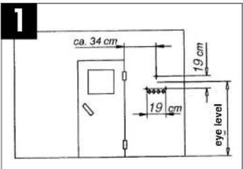
The controller should be mounted on one of the external sauna walls near the heater as is shown in Fig. 1. In most cases, the mounting location is already determined by empty cable conduits. The controller with the cable bushings is then fastened over the conduits.
Disassembling the case cover
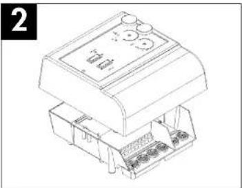
The fixing screws can be undone using a recessed head screwdriver through the side holes in the front cover.
After removing both fixing screws and pulling off the rotary knobs, the case cover can be detached (Fig. 2).
natural_image
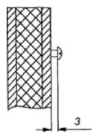
Line drawing of a mechanical device with control panel and base components (no text or symbols)Turn in the first screw (4x20 mm) approximately 3 mm as is shown in Figure 3 and hook on the case. Position the case horizontally and fasten with the left and right screws.
Use a sharp knife to enlarge the cable holes to the size required for the electrical cables.
3
Electrical connection:
Ensure that electrical connection work is performed exclusively by an authorized electrician and that it is in accordance with the guidelines set by the local power supply company as well as the applicable VDE standard for sauna heaters.
It is essential for the controller to be soundly connected to the power supply. The customer is responsible for installing a disconnecting device that disconnects all poles from the power supply at a minimum distance of 3 mm. It also important to ensure that all electrical components, such as cables, lamps, etc. are able to withstand a minimum temperature of 140°C. All flexible cables must have connector sleeves.
Cable cross sections depend on the heater being used and are described in the operating manual of the respective heater. A cross section of 2.5 mm_ should be used in order to obtain the maximum output (9 KW) from the sauna controller.
Important note:
- The neutral conductor (N) of the heater must always be connected to the sauna controller, otherwise malfunctions could occur.
Connecting the sauna heater:
Position the sauna heater in front of the air intake opening as per the assembly instructions provided by the manufacturer and feed the silicon cables through the empty cable conduits up to the controller. Note: If there are no empty cable conduits inside the sauna, drill a hole next to the air intake opening and feed the silicon cable along the outside to the controller through a suitable wiring conduit or cable duct. Connect the stripped ends of the various wires (PE, N, U, V, W) as per the terminal diagram glued inside the controller case.
Connecting the sauna light:
The sauna light must be able to withstand temperatures of at least 140^ and has to be splash proof (IP54). Ensure that the sauna light is never mounted near the heater but always in the place stipulated by the sauna manufacturer.
The power cable must also be able to withstand temperatures of at least 140^ C. Connect the stripped ends of the various wires (N, L1, PE) as per the terminal diagram glued inside the controller case.
Important note:
After installation, all cables must be checked for short circuits. The cable for the overtemperature cut-out is especially important or there will be no guarantee that the controller is switched off in the event of a malfunction.
Connecting the temperature sensor and
overtemperature cut-out
Never place cables designed to withstand 140°C next to the mains cables, otherwise malfunctions could eventually occur.
Note:
The measurements in the diagram below are taken from those listed in device testing regulation EN 60335-53-2. It is essential that the heater sensor is mounted in the part of the sauna where the highest temperatures are to be expected.
Assembly in a sauna measuring 2m x 2m - Figure 4 Assembly in a sauna bigger than 2m x 2m - Figure 5

Fig. 4
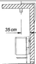
Fig. 5
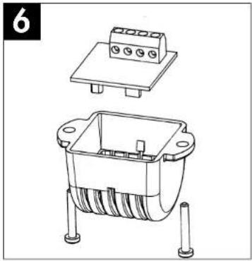
Insert the power cable of the temperature sensor (terminals marked „white“ 1 and 2) and the overtemperature sensor (red 1 and red 2) through the pre-drilled 8 mm hole in the ceiling. Now clamp one of the two wires of the white cable to white
terminal 1 (Fig. 6) and the other wire to white terminal 2 (Fig. 6) of the sensor circuit board. Repeat this process for the red cable by clamping its wires to red terminals 1 and 2 (Fig. 6). Finally, clamp the white cable to the terminals marked "white 1" and "white 2" and the red cable to the terminals marked "red 1" and "red 2" as per the terminal diagram found in the controller case. You can now snap the printed circuit board into the protective case and affix it to the ceiling with the two 3 × 16 mm screws.
natural_image
Technical line drawing of an electronic component with a top panel and base housing (no text or symbols)Operation and functions

Refer to Figure 7 for the layout of the operator controls.
1 = Heater switch
2 = Light switch
3 = Regulator knob for temperatures of
70°C to 110°C
4 = Regulator knob for timer
5 = Standby diode
6 = Heating mode diode
Operation:
Set switch No. 1 to HEAT, which illuminates the green LED. You can alter the temperature inside the sauna to the desired temperature using the regulator knob. Depending on the temperature in the sauna at the time, the red LED will illuminate to indicate that heating is in process. Turning the regulator clockwise increases the temperature; turning the regulator counterclockwise decreases the temperature. The controllable temperature range is between approx. 40°C and 110°C. Please take into account that the reading you see on the thermometer in the sauna may deviate from the temperature you programmed into the sauna controller as the regulating sensor is located directly in the hot air current of the heater. However, the regulation mechanism is configured so that normal spa temperatures are achieved in the sauna.
Use of the timer:
To set a time when the heating process should begin, turn the timer regulator knob (Fig. 7, Item 1) to the desired time interval.
Timer function:
The power switch (Fig. 7. Item 1) must be turned off. Enter the desired amount of time before heating begins.
Turn on the power switch [timer activation is signified by a flashing heat diode (Item 6)].
Note that, for safety reasons, the time can only be altered when the unit is switched off. Adjusting the regulator (Fig. 7, Item 4) has no effect on the previously entered time. If you would like to alter the previously entered time, you must first turn off the power switch, change the time, then turn the switch on again. The time registered when switching the power on is the new starting time for the timer.
Malfunctions:
If the green operating diode does not illuminate after switching on, check that all 3 phases contact the 230 V neutral conductor on the incoming wire.
The device can be switched on (i.e. green LED is lit), the heater warms up, but the preset temperature is not reached.
- Check the sensor cable.
- Check the power supply to the heater (all 3 phases must contact the zero conductor.)
- The regulator knob must stop when turned all the way to the right and to the left and must not rotate around its axis.
The unit can be switched on, but the heater does not warm up.
- Check the overtemperature cut-out in the sensor
case. Resistance is approximately 0 ohms. - Check the KTY sensor in the sensor case.
Resistance is approximately 1 kOhm at 21°C. Check the cables leading to the sensor case for short circuits and disconnections. - The unit cannot be switched on but the LED flashes.
- Check the timer. If necessary, turn the timer knob to the left, switch off the controller, then switch it back on.
Check the overtemperature cut-out:
The controller is equipped with an overtemperature cut-out in the sensor case which in the event of overtemperature, e.g. due to a defective controller, forces the system to cut out at 127°C. A tripped overtemperature cut-out is defective and the sensor circuit board must be replaced.
Note for the electrician:
Bridge the overtemperature cut-out (strictly for testing purposes only)
- Measure the voltage at the connector terminals. A defective overtemperature cut-out reads approx. 24 V \~.
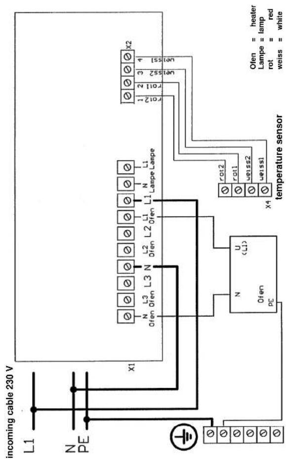
Terminal diagram for 7.5 kW and 9 kW heaters

Terminal diagram for 3.3 kW heaters
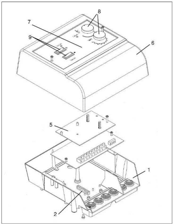
Replacement parts diagram for the ESS 9000-T model
B
Internationals Service Center
Eschenstraße 6
D-94405 Landau/Isar
Description of machinery: Sauna Controller
Typ
Type of machinery: ESS 9000-T
IEC 1000-4-2; IEC 1000-4-4; IEC 1000-4-5; IEC 1000-4-6; IEC 1000-4-11
The guarantee period begins on the sales date and is valid for 1 year. Responsibility is assumed for faulty construction or material or functional defects. Any necessary replacement parts an necessary repair work are free of charge. We do not assume responsibility for consequential damage.
Your customer service partner
GB Einhell UK Ltd
Brook House, Brookway
North Chesire Trading Estate
Prenton, Wirral, Chesire
CH 43 3DS
Tel. 0151 6084802, Fax 0151 6086339
Technical changes subject to change
58.547.92 - wegm. 11/2000
- Assembly and Operating Instructions Sauna Controller
- Safety precautions:
- Technical data:
- Delivery Items supplied:
- Assembly:
- Electrical connection:
- Important note:
- Connecting the sauna heater:
- Connecting the sauna light:
- Connecting the temperature sensor and
- overtemperature cut-out
- Note:
- Operation:
- Use of the timer:
- Timer function:
- Malfunctions:
- Check the overtemperature cut-out:
- Note for the electrician:
Brand : EINHELL
Model : ESS 9000-T
Category : Temperature regulator