DFG 20K X - Measurement PCE Instruments - Free user manual and instructions
Find the device manual for free DFG 20K X PCE Instruments in PDF.


| Product Type | Digital Force Gauge |
| Model | DFG 20K X |
| Brand | PCE Instruments |
| Measurement Range | 0 - 20 kN (0 - 2000 kg) |
| Resolution | 0.001 kN (0.1 kg) |
| Accuracy | ±0.1% of full scale |
| Display | Backlit LCD, 5 digits |
| Units | N, kN, kg, lb, oz |
| Data Output | USB, RS-232, analog output |
| Memory | Up to 1000 measurements |
| Sampling Rate | 1000 Hz |
| Overload Protection | 150% of full scale |
| Power Supply | Rechargeable Li-ion battery (3.7V, 3400 mAh) or AC adapter |
| Battery Life | Approx. 12 hours continuous use |
| Dimensions | 200 x 80 x 40 mm (7.9 x 3.1 x 1.6 in) |
| Weight | Approx. 650 g (1.43 lb) |
| Operating Temperature | 0°C to 40°C (32°F to 104°F) |
| Housing Material | Aluminum and ABS plastic |
| Included Accessories | AC adapter, USB cable, carrying case, hook, flat tip, chisel tip, extension rod |
| Functions | Peak hold, real-time, average, preset limits, data logging, auto shut-off |
| Maintenance | Clean with dry cloth; calibrate annually; avoid moisture and dust |
| Safety | Do not exceed maximum load; wear safety goggles during high-force tests |
| Spare Parts | Available: battery, AC adapter, load cells, adapters |
| Repairability | Repairs by certified PCE service center recommended |
| User Manual | Downloadable PDF from PCE Instruments website |
Frequently Asked Questions - DFG 20K X PCE Instruments
User questions about DFG 20K X PCE Instruments
0 question about this device. Answer the ones you know or ask your own.
Ask a new question about this device
Download the instructions for your Measurement in PDF format for free! Find your manual DFG 20K X - PCE Instruments and take your electronic device back in hand. On this page are published all the documents necessary for the use of your device. DFG 20K X by PCE Instruments.
USER MANUAL DFG 20K X PCE Instruments
User manuals in various languages (français, italiano, español, português, nederlands, türk, polski, русский, 中文) can be found by using our product search on: www.pce-instruments.com
1 Safety notes....42
2 Specifications....43
2.1 Force gauge with internal load cell 43
2.2 Force gauge with external load cell 43
2.3 Delivery scope....44
2.4 Accessories....45
3 System description 45
3.1 Device....45
3.2 Model with external load cell 45
3.3 Model with internal load cell 46
3.4 Keypad....46
3.5 Display....47
3.6 Function keys....54
4 Preparation 55
4.1 Power supply ....55
4.2 Start-up....55
5 Operation 0
5.1 Measurements....0
5.2 Main menu 0
5.3 Software....39
6 Contact....40
7 Disposal 40
natural_image
Close-up of a black electronic device with a circular connector and ventilation grille (no visible text or symbols)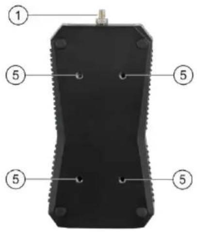
line
| Time (s) | Value | | -------- | ----- | | 02:11:23 | 30 | | 13:22 | 46 |3.5.1.4 Schieber
natural_image
Simple red battery icon on black background (no text or symbols)5.3 Software
Please read this user manual carefully and completely before operating the unit for the first time. The appliance may only be used by carefully trained personnel. Damage caused by non-observance of the instructions in the user manual is exempt from any liability.
- This meter may only be used in the manner described in this instruction manual. If the meter is used in any other way, dangerous situations may arise.
- Only use the measuring device if the ambient conditions (temperature, humidity, ...) are within the limits specified in the specifications. Do not expose the device to extreme temperatures, direct sunlight, extreme humidity or moisture.
- Do not subject the unit to shocks or strong vibrations.
- The device housing may only be opened by qualified personnel of PCE Deutschland GmbH.
- Never use the meter with wet hands.
- No technical modifications may be made to the unit.
- The unit should only be cleaned with a cloth. Do not use scouring agents or cleaning agents containing solvents.
- The device may only be used with the accessories offered by PCE Deutschland GmbH or equivalent replacements.
- Check the housing of the meter for visible damage before each use. If there is any visible damage, the unit must not be used.
- The measuring device must not be used in an explosive atmosphere.
- The measuring range given in the specifications must not be exceeded under any circumstances.
- Failure to observe the safety instructions may result in damage to the unit and injury to the operator.
We accept no liability for printing errors and mistakes in the content of these instructions. We expressly refer to our general warranty conditions, which you will find in our General Terms and Conditions.
2 Specifications
2.1 Force gauge with internal load cell
2.1.1 Technical specifications
| Specification | Explanation | |||||
| Model | PCE-DFG 5 X | PCE-DFG 10 X | PCE-DFG 20 X | PCE-DFG 200 X | PCE-DFG 500 X | PCE-DFG 1000 X |
| Measurement range | 0...5 N | 0...10 N | 0...20 N | 0...200 N | 0...500 N | 0...1000 N |
| Resolution | 0.001 N | 0.005 N | 0.01 N | 0.1 N | 0.1 N | 0.5 N |
| Accuracy | 0.05 % FS | |||||
| Dimensions | 165 x 85 x 32 mm | |||||
| Weight | approx. 540 g | |||||
2.2 Force gauge with external load cell
2.2.1 Technical specifications
| Specification | Explanation | ||||
| Model | PCE-DFG 1K X | PCE-DFG 2K5 X | PCE-DFG 5K X | PCE-DFG 10K X | |
| Measurement range | 1,000 N / 100 kg | 2,500 N / 250 kg | 5,000 N / 500 kg | 10,000 N / 1 t | |
| Resolution | 0.5 N | 1 N | 1 N | 2 N | |
| Weight (load cell only) | 520 g | 520 g | 524 g | 658 g | |
| Model | PCE-DFG 20K X | PCE-DFG 50K X | PCE-DFG 100K X | ||
| Measurement range | 20,000 N / 2 t | 50,000 N / 5 t | 100,000 N / 10 t | ||
| Resolution | 0.002 kN / 2 N | 0.005 kN / 5 N | 0.01 kN / 10 N | ||
| Weight (load cell only) | 1294 g | 1374 g | 5200 g | ||
| Accuracy | 0.05 % FS | ||||
| Safe overload | 150 % FS | ||||
| Ultimate overload | 300 % FS | ||||
| Operating temperature | -35 ... +65 °C | ||||
| Storage temperature | -40 ... +70 °C | ||||
| Material | nickel plated alloy steel | ||||
| Protection class | IP67 | ||||
2.2.2 Dimensions
| Model | Load | L | H | W1 | W | H1 | Thread |
| PCE-DFG 1K X | 100 kg / 1000 N | 50.8 | 76.2 | 19 | 22.4 | 15.3 | M10 x 1.5 |
| PCE-DFG 2K5 X | 250 kg / 2000 N | 50.8 | 76.2 | 19 | 22.4 | 14.4 | M12 x 1.75 |
| PCE-DFG 5K X | 500 kg / 5000 N | 50.8 | 76.2 | 19 | 22.4 | 14.4 | M12 x 1.75 |
| PCE-DFG 10K X | 1000 kg / 10,000 N | 50.8 | 76.2 | 25.4 | 28.8 | 12.5 | M12 x 1.75 |
| PCE-DFG 20K X | 2500 kg / 20,000 N | 76.2 | 101.6 | 25.4 | 28.8 | 20 | M20 x 1.5 |
| PCE-DFG 50K X | 5000 kg / 50,000 N | 76.2 | 101.6 | 25.4 | 28.8 | 20 | M20 x 1.5 |
| PCE-DFG 100K X | 10,000 kg / 100,000 N | 125 | 175 | 50 | 40.2 | M33 x 3 |
Other versions on request
2.2.3 General technical data
| Specification | Explanation |
| Display | 2.8" LCD |
| Alarm modes | Overrun, Undercutting, Window mode, Inverse window mode |
| Units | g, kg, t, lb, N, kN, Pa, kPa, Nm, Ncm, lb ft |
| Alarm type | visual, acoustic |
| Sampling rate | 1 ... 7200 Hz |
| Unit system | metric / imperial |
| Calibration | mV/V; individually up to 15 measuring points |
| Menu languages | English, German, French, Spanish, Italian, Dutch, Portuguese, Turkish, Polish, Russian, Chinese, Japanese, Danish |
| Operating and storage conditions | -20 ... +65 °C, 10 ... 95 % RH, non-condensing |
| Data logger | 32 GB storage capacity30 x 1 million data points |
| Sampling rate data logger | 1 ... 7200 Hz |
| Interface | USB-C (for online measurement and readout of the internal memory) |
| Protection class cell | IP 67 |
| Protection class | IP52 |
| Auto power off | user selectable: 1, 5, 15 min |
| Power supply | internal: LiPo battery (7.4 V DC, 2200 mAh)external: USB 5 V DC, 500 mA |
| Operating time | approx. 13 h |
| Dimensions | 165 x 85 x 32 mm |
| Weight | 255 g (model with external load cell only handheld) |
2.3 Delivery scope
Variant with internal cell:
1 x force gauge PCE-DFG X
5 x test head adaptor (pointed head, notched head, chisel head, flat head, hook)
1 x extension pole incl. adaptor
1 x carrying case
1 x USB-C cable
1 x PC software
Variant with external cell:
1 x force gauge PCE-DFG X
1 x load cell
2 x eyebolt (only up to 10 kN cells)
1 x carrying case
1 x USB-C cable
1 x PC software
1 x user manual

PCE
INSTRUMENTS
1 x user manual
2.4 Accessories
USB mains adaptor: NET-USB-EU
3 System description
3.1 Device
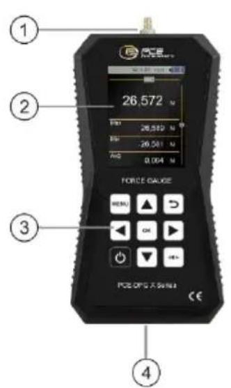
3.2 Model with external load cell
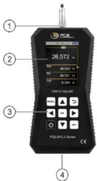
- Load cell connector
- Display
- Keyboard
- USB-C port
natural_image
Close-up of a black electronic device with a circular connector and ventilation grille (no visible text or symbols)3.3 Model with internal load cell
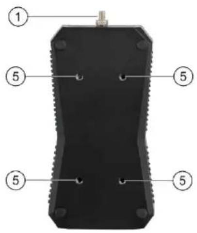
- Load cell with M6 thread connector
- Display
- Keyboard
- USB-C port
- 4 x M5 mounting holes
3.4 Keypad
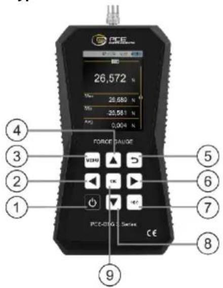
- On/off key
- Left key
- MENU key
- Up key
- Back key
- Right key
- Down key
- OK key
3.5 Display
3.5.1 Display modes
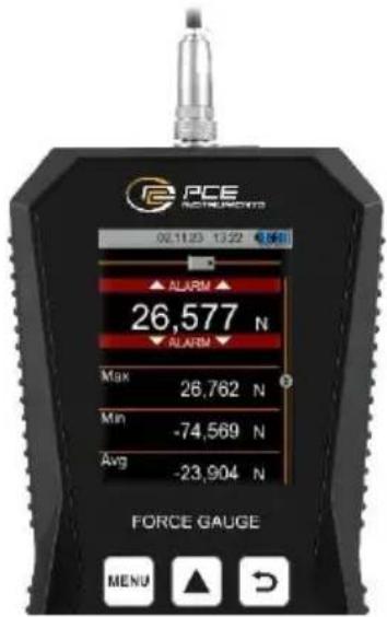
The ▲/▼ keys are used to switch between the individual display modes. Depending on the display mode, the position of the page is marked on the vertical scroll bar. If you are on the top level and press the ▲ key, you will reach the lowest level. If you are on the lowest level and press the ▼ key, you will reach the top level.
| Level | Display type | Description |
| 1 | Numerical display | Numerical display of the current measured value. Above the numerical value, a slider is displayed which shows the measured value as a deflection depending on the measuring direction. |
| 2 | Statistical display | In this display, statistical measured values are shown in the selected unit in addition to the numerical value. The maximum, minimum and average measured values of the current measurement are displayed. |
| 3 | Graphical display | In addition to the numerical view, a graph of the current measurement is displayed. The graph always shows the last 15 seconds of the ongoing measurement. |
3.5.1.1 Numerical display
The numerical display shows the measurement value in the set unit. When no load cell is connected, no number will be displayed, only five horizontal lines.
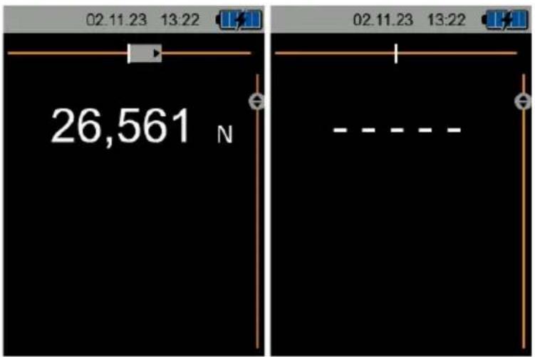
3.5.1.2 Statistical display
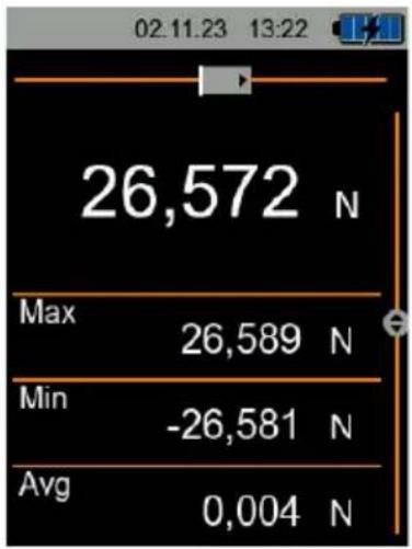
other
| Metric | Value | | :--- | :--- | | Max | 26,589 | | Min | -26,581 | | Avg | 0,004 | 26,572 N (top value) 26,572 N (bottom value)3.5.1.3 Graphical display
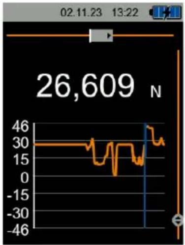
line
| Time (s) | Value | | -------- | ----- | | 02.11.23 | 30 | | 13:22 | 46 |3.5.1.4 Slider
The slider shows the current measured value within the measurement range. You can select which direction for the applied force (tension or compression) is positive. The slider moves to the right when a value is positive and moves to the left when a value is negative.
| Force type | Display | |
| Tensile force | ||
| Compressive force | ||
3.5.2 Alarm
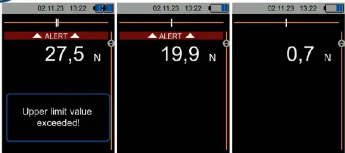
When an alarm event occurs, a dialogue box appears, indicating that a measured value is above or below or inside or outside the alarm window. The frame changes colours at intervals of one second and the beeper beeps at the same interval. In addition, depending on the alarm type, an alarm visualization is displayed above or below the numerical display.
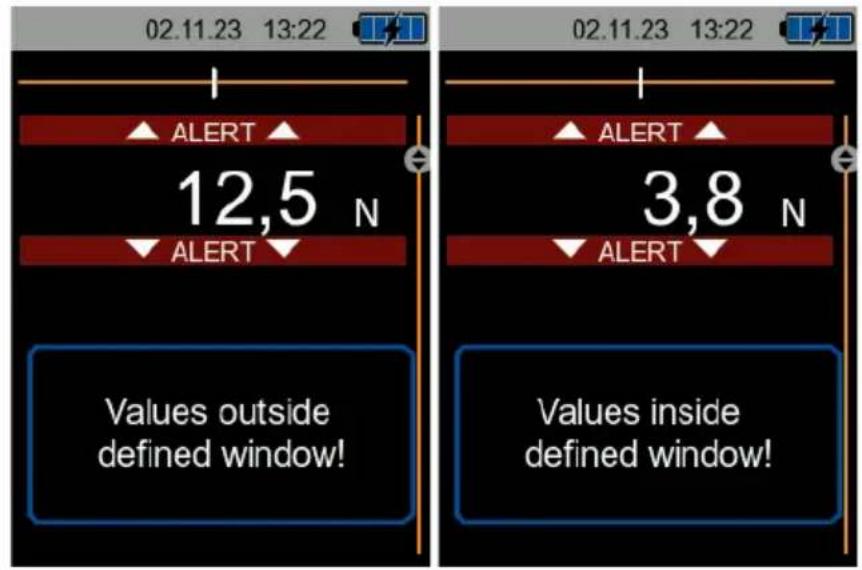
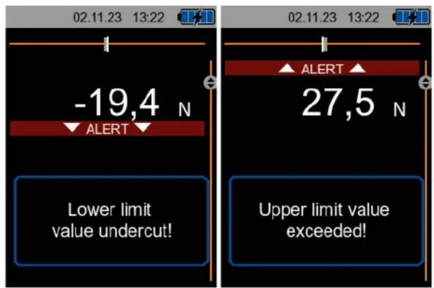
If the back key is pressed, the dialogue box will disappear and then, the alarm banner will disappear if the conditions for the alarm are no longer fulfilled.

PCE
INSTRUMENTS
3.5.3 Top bar
The top bar provides some information which is explained in more detail in the following section.
3.5.3.1 Date / time
The date and time are displayed centrally in the set date and time format.
18.10.22 07:42

3.5.3.2 Battery status
The battery display shows the current battery level. The battery voltage is measured by the microcontroller at 5-minute intervals and converted to the nominal voltage of the battery as a percentage.
| Battery status | Representation |
| 0 % | 18.10.22 07:42 |
| 20 % | 18.10.22 07:42 |
| 40 % | 18.10.22 07:42 |
| 60 % | 18.10.22 07:42 |
| 80 % | 18.10.22 07:42 |
| 100 % | 18.10.22 07:42 |
3.5.3.3 Charging indicator
When the meter is connected to a USB charger or PC, the battery indicator is animated. The animation of the charging progress starts at the current battery level and continues to 100% and then starts again at the current charge level until the battery is fully charged.
| Charge status | Representation |
| 0 % | 18.10.22 07:42 |
| 20 % | 18.10.22 07:42 |
| 40 % | 18.10.22 07:42 |
| 60 % | 18.10.22 07:42 |
| 80 % | 18.10.22 07:42 |
| 100 % | 18.10.22 07:42 |
3.5.3.4 PC connection
When the meter is connected with a PC, the connection symbol is displayed in the top bar. The battery continues to be charged when the PC connection is active and the animation described above is displayed. If there is no active connection with the software, the normal charging display is shown, see below.
| Charge status | Representation |
| 0 % | 18.10.22 07:42 |
| 20 % | 18.10.22 07:42 |
| 40 % | 18.10.22 07:42 |
| 60 % | 18.10.22 07:42 |
| 80 % | 18.10.22 07:42 |
| 100 % | 18.10.22 07:42 |
3.5.3.5 Data logger
Two different statuses for the data logger can be displayed in the top bar.
| Data logger status | Description | Representation |
| Triggered | Indicates that a data recording is scheduled, either by date/time or by limit value | |
| Active | Represents an active data recording. The red dot flashes at one second intervals during recording. |
3.6 Function keys
| Key | Designation | Function in the measurement screen | Menu function | Function in the settings |
 | On/Off | press and hold: turns off the device | ||
 | MENU | opens the main menu | ||
 | Back | short keystroke: back to numerical view press and hold: reset statistics | cancel, back | cancel, back |
 | OK | press and hold: opens data logger dialogue | confirm | confirm |
 | Zero | short keystroke: sets current measured value to 0 | ||
 | Up | selects previous display screen | navigate ▲ | increase digit value scroll ▲ in selected option |
 | Down | selects next display screen | navigate ▼ | decrease digit value scroll ▼ in selected option |
 | Right | freezes measured value | navigate ▶ | move cursor ▶ |
 | Left | no function | navigate ◀ | move cursor ◀ |
4 Preparation
4.1 Power supply
An internal LiPo battery serves as the power supply. With a fully charged battery, a runtime of approx. 8 ... 10 hours is possible, depending on the display brightness. The battery is charged via the USB port at the bottom of the meter and appropriate USB chargers can be used. The charging process can be shortened by switching off the meter during the charging process.
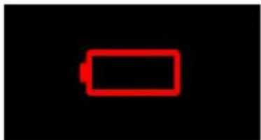
The current battery charge level is displayed in the status bar at the top right. As soon as the battery charge level is no longer sufficient for proper operation of the instrument, it switches off automatically and the screen shown below is displayed.
natural_image
Simple red battery icon on black background (no text or symbols)Fig. 1 Automatic Power Off
4.2 Start-up
4.2.1 Switch on
The meter is switched on by holding down the on/off key for approx. 5 seconds. When the meter is switched on, the start screen with the PCE logo appears for approx. 1 second and then the device switches to the measurement screen.
4.2.2 Switch off
To switch off the meter, press and hold the on/off key for approx. 3 seconds. A dialogue appears on the screen with a countdown that announces that the meter is to be switched off.
4.2.3 Sensor connection (for force gauges with external measuring cell)
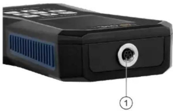
The load cell is screwed to the meter by means of the test cable. Connect the test cable to the meter via the plug connection and then secure it with the knurled nut.
4.2.4 Sensor disconnection
The load cell and the meter are disconnected by unlocking the knurled nut and then removing the plug of the test cable from the meter. Then loosen the screw connection between the load cell and the test cable.

5 Operation
5.1 Measurements
If the force gauge is connected, it will start displaying the measured data at a refresh rate that can be configured in the menu.
5.2 Main menu
In the main menu, you can view or change the following parameters: Measurement (settings for the measurement), Data logger, Settings, Calibration, Manual and Info.
| Menu item | Level 1 | Level 2 | Level 3 | Setting |
| Measurement | Units | Measurement units | GramKilogramTonPoundNewtonKilonewtonPascalKilopascalNewton metreNewton centimetrePound foot | |
| Surface units | m^2 cm^2 ft^2 | |||
| Surface | Surface value | |||
| Alert | Mode | OffOverrunUndercuttingWindow modeInverse window mode | ||
| Alarm limits | Upper limit | Upper limit | ||
| Lower limit | Lower limit |

PCE INSTRUMENTS
| Alarm sound | OnOff | |||
| Gravity value | Gravity value | |||
| Zero's threshold | Value range of the measurement that means zero | |||
| Measuring direction | CompressionTension | |||
| Data logger | Start condition | Manual | OK/NOK | |
| Date & time | Date and time | |||
| Limit | Limit value | |||
| Stop condition | Manual | OK/NOK | ||
| Date & time | Date and time | |||
| Limit | Limit value | |||
| Duration | Duration of recording | |||
| Sampling rate | Hz | |||
| Records | View the saved data | |||
| Delete all | Delete the records | |||
| Settings | Decimal separator | Comma | OK/NOK | |
| Dot | OK/NOK | |||
| Date & time | Set time | Time | ||
| Set date | Date | |||
| Date format | Date format | |||
| Time format | Time format | |||
| Display | Brightness | Brightness in % | ||
| Display rotation | Rotation of the display in ^9 | |||
| Screen saver | Brightness | Brightness in % | ||
| Time | Time until the display darkens | |||
| Update interval | Amount of time that it takes to display a new measurement on the display | |||
| Language | EnglishGermanFrenchSpanish | OK/NOK |

| ItalianDutchPortugueseTurkishPolishRussianChineseDanishJapanese | ||||
| Auto power off | Off | OK/NOK | ||
| 1 minute | OK/NOK | |||
| 5 minutes | OK/NOK | |||
| 15 minutes | OK/NOK | |||
| Key tones | OnOff | |||
| Factorysettings | OK/NOK | |||
| Calibration | Calibration info | Last calibration date | ||
| Next calibration date | ||||
| Factory calibration | Indicates if the device has PCE factory calibration | |||
| Calibration number | Indicates how many times the device has been calibrated | |||
| Calibrationreminder | Reminder | OK/NOK | ||
| Reminder period | Indicates how much time before the calibration date the reminder is shown | |||
| Calibration interval | Indicated after how much time the device has to be calibrated | |||
| Calibrationparameters fortechnicians | Sensitivity (mV/V) | Maximum load units | Unit selected for the maximum load and the calibration curves | |
| Maximum load | Typical maximum load the gauge can support in newton | |||
| Sensitivity | Sensitivity of the gauge in mV/V | |||
| Zero offset | Setting the zero offset |

PCE INSTRUMENTS
| Characteristics | Mode | New: creates a new calibration tableEdit: modifies the current calibration table | ||
| Calibration points | Number of calibration points for the table | |||
| Table | Table of points for the calibration | |||
| Gravity value | Gravity value in m/s^2 used for the calibration | |||
| High resolution | OnOffEnables adding another decimal place to the measurement | |||
| Calibration mode | Lets the technician select the calibration mode used for the measurements between "Curves" mode and "Sensitivity" mode | |||
| Clear all the memory | Clears the memory, even the stored calibration | |||
| Reset | Resets the calibration | |||
| Calibration parameters for customers (code 1703) | Sensitivity (mV/V) | Maximum load units | Unit selected for the maximum load and the calibration curves | |
| Maximum load | Typical maximum load the gauge can support in newton | |||
| Sensitivity | Sensitivity of the gauge in mV/V | |||
| Zero offset | Setting the zero offset | |||
| Gravity value | Gravity value in m/s^2 used for the calibration | |||
| High resolution | OnOffEnables adding another decimal place to the measurement | |||
| Reset to factory loadcell | Restores the first calibration stored in the device | |||
| Manual | Displays a QR code with the manual of the device | |||
| Info | Displays the name, the serial number and the firmware version of the device along with the website |
5.2.1 Main menu
Press the MENU key to enter the main menu. When you navigate to the main menu from the measurement screen using the MENU key, the Measurement item is selected by default. When you return to the main menu from a submenu using the back key, the previously selected menu item is highlighted. Use the ▲/▼ keys to select a submenu item and press the OK key to enter the selected submenu.
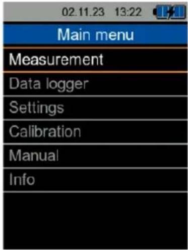
To exit the main menu and return to the measurement screen, press the back key.
The individual submenus and settings are described in more detail below.
5.2.2 Measurement
In the submenu Measurement, the options relevant for the measurement can be set. In the main menu, use the ▲/▼ keys to select the Measurement menu item and press the OK key to enter it.
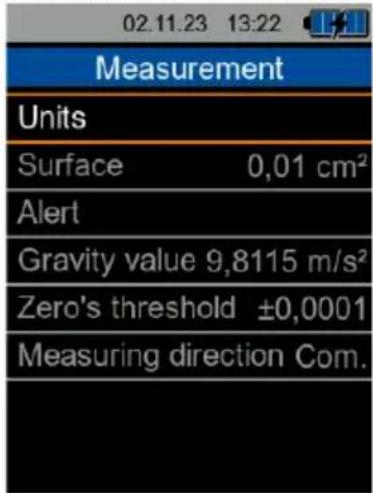
The following options can be set in this submenu:
| Menu item | Description |
| Units | Units for force, weight, pressure and torque are adjustable. |
| Surface | To measure the pressure in Pa, the area can be set here. |
| Alarm | The configuration for the visual and acoustic alarm of the meter is carried out in the Alarm menu. |
| Gravity value | Relevant gravitational value at the measuring point in m/s ^2 |
| Zero's threshold | The adjustable threshold value is the measured value up to which the force gauge displays 0 until the actual measured value is to be shown on the display. |
| Measuring direction | Specifies whether a positive measured value should be displayed for tensile tests or for compression tests. |
5.2.2.1 Unit
In the Unit menu, the force and surface units can be set.
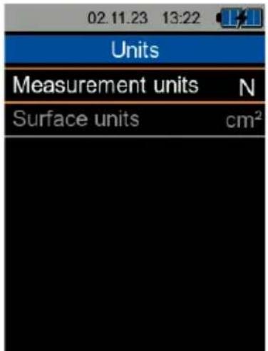
The following units are available for the measurement:
| Measured variable | Unit | Abbreviation |
| Force | Newton, kilonewton | N, kN |
| Weight | Gramme, kilogramme, ton | g, kg, t |
| Pound | lb | |
| Pressure^3 | Kilopascal | kPA |
| Torque^4 | Newton centimetre, newton metre, pound feet | Ncm, Nm, lb ft |
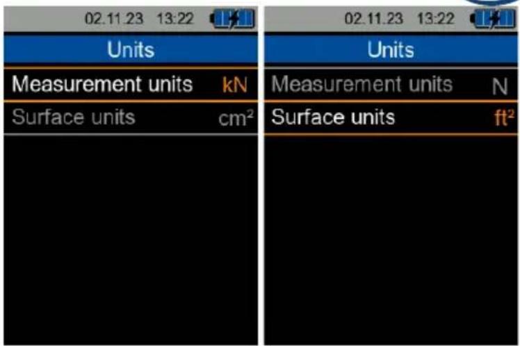
In the Measurement submenu, select the Unit menu item. Here, select Measurement units and use the ▲ or ▼ key to select the desired unit and press OK to confirm it.
In the Surface units menu item, you can select the unit for the surface value that has to be entered in order to calculate the pressure. You can select the unit m^2 , cm^2 or ft^2 .
5.2.2.2 Surface
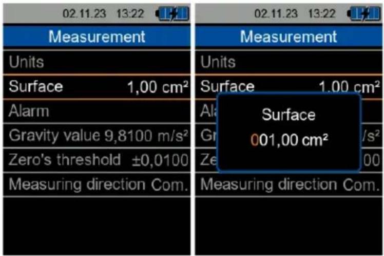
It is also possible to set the surface value. The surface value can be set to a value from 0.01 cm² to 999.99 cm² and is used for the calculation of the pressure if the display unit "kPA" or "Pa" has been selected.
Use the ▲ or ▼ key to select the menu item Surface and press the OK key to change the value via the input dialogue. To change the value, use the ▶ key to select the digit to be adjusted. The digit to be changed is highlighted in orange. With the ▲/▼ keys, the selected digit can now be changed within the range 0 ... 9. To confirm the set value for the force area, press the OK key again and the device will go back to the Measurement menu automatically. To abort the setting, press the back key.
5.2.2.3 Alert
The configuration for the visual and acoustic alarm of the measurement is carried out in the Alert menu.
| Menu item | Description |
| Mode | Setting the alarm mode |
| Alert limits | Setting the lower and upper limits |
| Alert sound | Enabling or disabling the alarm sound |
In the Measurement menu, navigate to the menu item Alert with the ▲/▼ keys and press the OK key. The following display then appears.
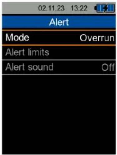
Press the back key to return to the measurement menu.
5.2.2.3.1 Select alert mode
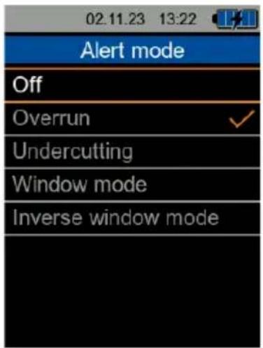
5 different alarm modes are available
| Mode | Description |
| Off | The alarm is deactivated. |
| Overrun | The alarm is triggered as soon as the measured variable exceeds the upper limit value. |
| Undercutting | The alarm is triggered as soon as the measured variable falls below the lower limit value. |
| Window mode | The alarm is triggered as soon as the measured variable is within the range between the upper and lower limit values. |
| Inverse window mode | The alarm is triggered as soon as the measured variable is outside the range between the upper and lower limit values. |
To select the mode, navigate to the Mode menu item with the ▲/▼ keys and press the OK key. In the following submenu, you can now select the mode with the ▲/▼ keys and confirm with the OK key. An orange tick is then displayed next to the selected setting. You can now return to the Alarm menu with the help of the back key.
5.2.2.3.2 Set alert limits
The alarm limits can be set under the menu item Alert limits. Use the ▲ or ▼key to select the menu item Alert limits and press the OK key to enter the submenu.
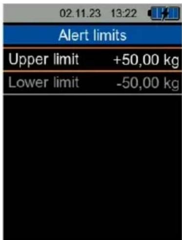
Use the ▲ or ▼key to select the menu item Upper limit or Lower limit and press the OK key to change the value in the input dialogue. To change the value, use the ▶ key to select the digit to be adjusted. The digit to be changed is highlighted in orange. With the ▲/▼keys, the selected digit can now be changed within the range 0 ... 9. To confirm the value set for the selected limit, press the OK key again. You can now return to the Alert menu by pressing the back key.
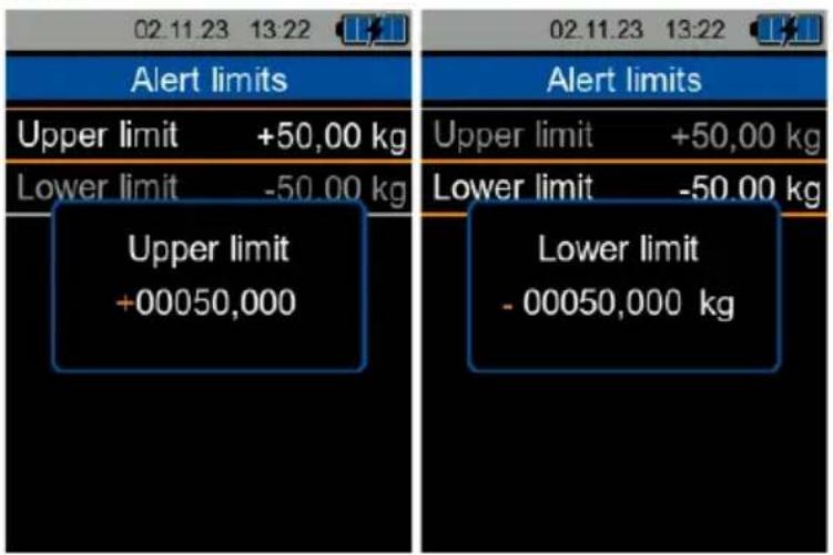
5.2.2.3.3 Alert sound
The alarm sound can be set or turned off. If it is turned off, the visual alarm will still be displayed. Use the ▲ or ▼ key to select the menu item Alert sound and press the OK key to enter the submenu.
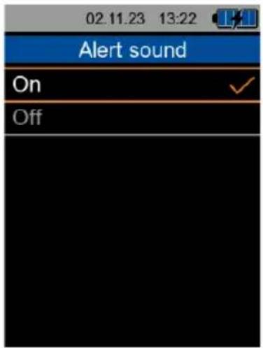
Use the ▲ or ▼ key to select the desired option and press the OK key to confirm. You can now return to the Alert menu by pressing the back key.
5.2.2.4 Gravity value
In this menu item, the gravitational value at the measuring point is entered with 4 decimal places with the ▲ key, e. g. 9.8115.
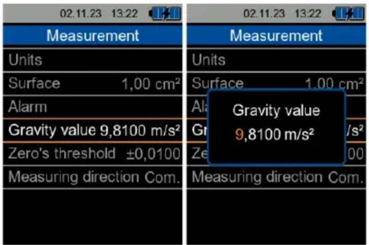
To change the value via the input dialogue, navigate to the Gravity value item using the ▲/▼ keys and press the OK key. Use the ▶ key to select the digit to be changed. The digit to be changed is highlighted in orange. Use the ▲/▼ keys to change the selected digit within the range 0 ... 9. To confirm the set value for the selected acceleration due to gravity, press the OK key again. You can now return to the Measurement menu by pressing the back key.
5.2.2.5 Zero's threshold
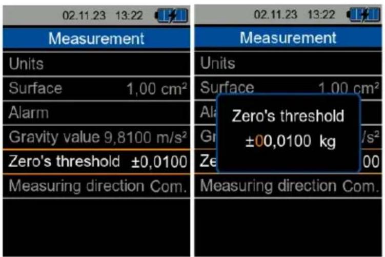
The adjustable threshold value is the measured value up to which the force gauge displays 0 until the actual measured value is to be shown on the display.
To change the value via the input dialogue, navigate to the Zero's threshold item using the ▲/▼ keys and press the OK key. Use the ▶ key to select the digit to be adjusted. The digit to be changed is highlighted in orange. Use the ▲/▼ keys to change the selected digit within the range 0 ... 9. To confirm the set value, press the OK key again. You can now return to the Measurement menu by pressing the back key.
5.2.2.6 Measuring direction
The measuring direction indicates whether the measured value for tensile tests or for compression tests is to be displayed as a positive value on the measuring screen.
To change the measuring direction between tension and compression, select the menu item Measuring direction with the ▲/▼ keys and press the OK key. You can now use the ▲/▼ keys to switch between the word Ten. (tension) and Com. (compression) marked in orange. Confirm the selection with the OK key. You can now return to the previous menu by pressing the back key.
| 02.11.23 13:22 | 02.11.23 13:22 | 02.11.23 13:22 |
| Measurement | Measurement | Measurement |
| Units | Units | Units |
| Surface 1,00 cm² | Surface 1,00 cm² | Surface 1,00 cm² |
| Alarm | Alarm | Alarm |
| Gravity value 9,8100 m/s² | Gravity value 9,8100 m/s² | Gravity value 9,8100 m/s² |
| Zero's threshold ±0,0100 | Zero's threshold ±0,0100 | Zero's threshold ±0,0100 |
| Measuring direction Com. | Measuring direction Com. | Measuring direction Ten. |
5.2.3 Data logger
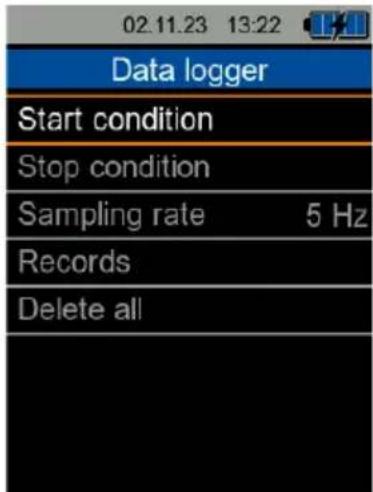
The data logger of the meter enables the recording of all measured values. The time period as well as the storage interval can be freely configured with the help of this menu. The menu contains the following items.
| Menu item | Description |
| Start condition | Sets the start condition for data logging |
| Stop condition | Sets the stop condition for data logging |
| Sampling rate | Sets the storage rate. This also corresponds to the sampling rate in the measurement settings. |
| Records | Listing of the saved measurement data in the meter |
| Delete all | Deletes all saved records |
Select the menu item Data logger in the main menu with the ▲/▼ keys and press the OK key. You can now use the ▲/▼ keys to mark the desired submenu in orange. Confirm your selection with the OK key.
5.2.3.1 Start condition
In the Start condition menu, you can set the conditions under which the data logger is started.
| Start condition | Description |
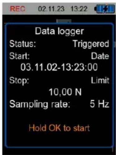
| Manual | Manual start of the data logger via the data logger dialogue in the measuring screen |
| Date & time | Automatic storage when a start date and time is reached |
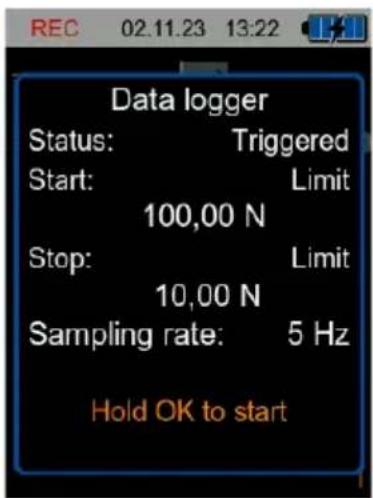
| Limit value | Automatic storage when a preset limit value is exceeded |
5.2.3.1.1 Starting the data logger manually
Use the ▲/▼ keys to select Manual as the start condition for the data logger and confirm the selection with the OK key. A tick appears next to the selection as confirmation. Manual is the factory default setting. You can now return to the previous menu by pressing the back key.
5.2.3.1.2 Start by date and time
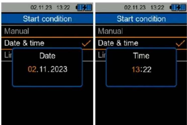
Select the Date & time item with the ▲/▼ keys and confirm the selection with the OK key to set a start date and time via the input dialogue.
An input dialogue will now open where you must first set the date. To change the date, use the ▶ key to select the digit to be changed. The digit to be changed is highlighted in orange. With the ▲/▼ keys, you can now select the day within the range 01 ... 31 (depending on the month), the month within the range 01 ... 12 and the year within the range 2023 ... 2060. To confirm the set value, press the OK key again.
The start time is then set. A new dialogue window opens automatically. To change the time, use the ▶ key to select the digit to be changed. The digit to be changed is highlighted in orange. The ▲/▼ keys can now be used to change the hours within the range 00 ... 24 (depending on the time format) and the minutes within the range 00 ... 59. To confirm the set value, press the OK key again.
The setting is accepted and an orange tick appears next to "Date & time". You can now return to the previous menu by pressing the back key.
Note:
At least the stop time must be in the future. Otherwise, the meter will give an error message.
5.2.3.1.3 Starting the data logger when the limit value is exceeded
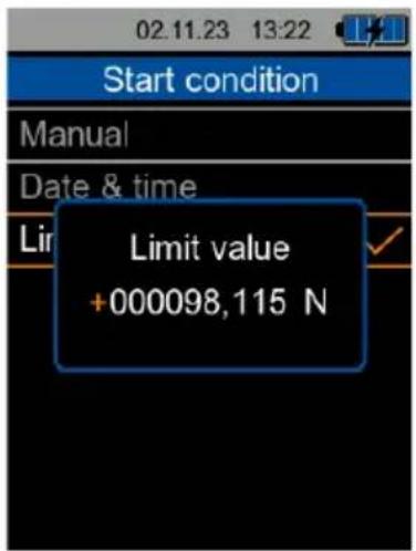
To change the value via the input dialogue, use the ▲/▼ keys to navigate to the item Limit value and press the OK key. To change the value, use the ▶ key to select the digit to be adjusted. The digit to be changed is highlighted in orange. Use the ▲/▼ keys to change the selected digit within the range 0 ... 9. To confirm the value set as the limit value, press the OK key again. Now the setting for the limit value is saved and the limit value is displayed in orange. You can now return to the previous menu by pressing the back key.
Note:
Ensure correct selection of Measuring direction for tensile and compression tests.
5.2.3.2 Stop condition
Three different options are available for stopping the data logger. Either the stop can be done manually via the data logger dialogue by pressing a key, on a date and time, below a limit or after an adjustable time interval.
| Stop condition | Description |
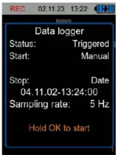
| Manual | Stopping the data logger manually via the data logger dialogue in the measuring screen |
| Date and time | Automatic termination when a stop date and time is reached |
| Limit value | Data logger is stopped when the value falls below the limit value |
| Duration | Stop of the data logger after a defined amount of time recording |
5.2.3.2.1 Stopping the data logger manually
Select Manual with the ▲/▼ keys to select manual as the stop condition for the data logger and confirm the selection with the OK key. A tick appears next to the selection as confirmation. Manual is the factory default setting. You can now return to the previous menu by pressing the back key.
5.2.3.2.2 Stop by date and time
Use the ▲/▼ keys to select Date & time and confirm the selection with the OK key to set a stop date and time via the input dialogue.
An input dialogue will now open where you must first set the date. Use the ▶ key to select the digit to be changed. The digit to be changed is highlighted in orange. With the ▲/▼ keys, you can now select the day within the range 01 ... 31 (depending on the month), the month within the range 01 ... 12 and the year within the range 2023 ... 2060. To confirm the set value, press the OK key again.
A new dialogue window opens automatically. Use the ▶ key to select the digit to be adjusted. The digit to be changed is highlighted in orange. The ▲/▼ keys can now be used to change the hour within the range 00 ... 24 (depending on the time format) and the minute within the range 00 ... 59. To confirm the set value, press the OK key again.
The setting is accepted and an orange tick appears next to "Date & time". You can now return to the previous menu by pressing the back key.
Note:
At least the stop time must be in the future and, if applicable, be later than the start date and time. Otherwise, the meter will give an error message.
5.2.3.2.3 Stopping the data logger when the value falls below the limit value
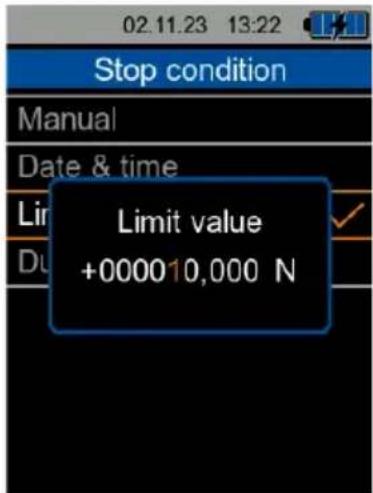
To change the value via the input dialogue, navigate to the item Limit value with the ▲/▼ keys and press the OK key. Use the ▶ key to select the digit to be adjusted. The digit to be changed is highlighted in orange. Use the ▲/▼ keys to change the selected digit within the range 0 ... 9. To confirm the value set as the limit value, press the OK key again. Now the setting for the limit value is saved and the limit value is displayed in orange. You can now return to the previous menu by pressing the back key.
Note:
Ensure correct selection of the Measuring direction for tension and compression tests. By default, the meter sets the limit value for the stop condition equal to the limit value of the start condition (if set).
5.2.3.2.4 Duration
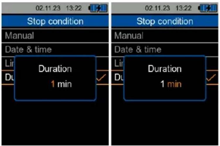
To change the value via the input dialogue, navigate to the item Duration with the ▲/▼ keys and press the OK key. Once the dialogue has opened, use the ▲/▼ keys to change the time value or the time unit, depending on which one is highlighted in orange. Use the ▶/◀ keys to change between the selection of the time value and the time unit. The value can be set in the range of 0 ... 59 seconds, 0 ... 59 minutes or 0 ... 12 hours. To confirm that value, press the OK key again. Now the setting for the duration is saved. You can now return to the previous menu by pressing the back key.
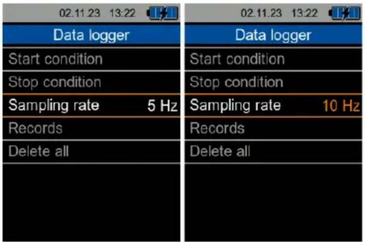
5.2.3.3 Sampling rate
Select Sampling rate with the ▲/▼ keys in the Data logger menu to select the desired sampling rate for the session and press the OK key. The sampling rate value is highlighted in orange. By pressing the ▲/▼ keys, the value can be changed and to confirm the set value, press the OK key again. You can now return to the previous menu by pressing the back key. When you are in the main screen and data is being displayed without datalogging running, the sampling rate is automatically set to 5 Hz but when a datalogging session is launched, it is automatically switched to this value.
5.2.3.4 Records
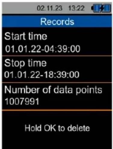
In this menu, all saved records are displayed and by selecting a record, information on the start and stop time as well as the number of saved data points is displayed. One data point corresponds to the one-time storage of all measured variables.
Use the ▲/▼ keys to select the item Records and confirm the selection with the OK key to view the overview of all data sets. The last record saved is automatically highlighted.
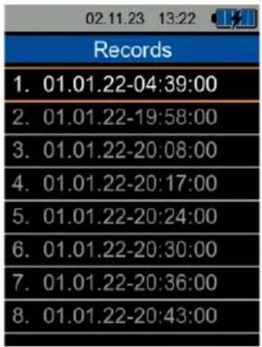
Now select the record using the ▲/▼ keys and confirm the selection with the OK key. The file information is now displayed as follows. Press the back key to return to the previous view.
5.2.3.5 Delete all
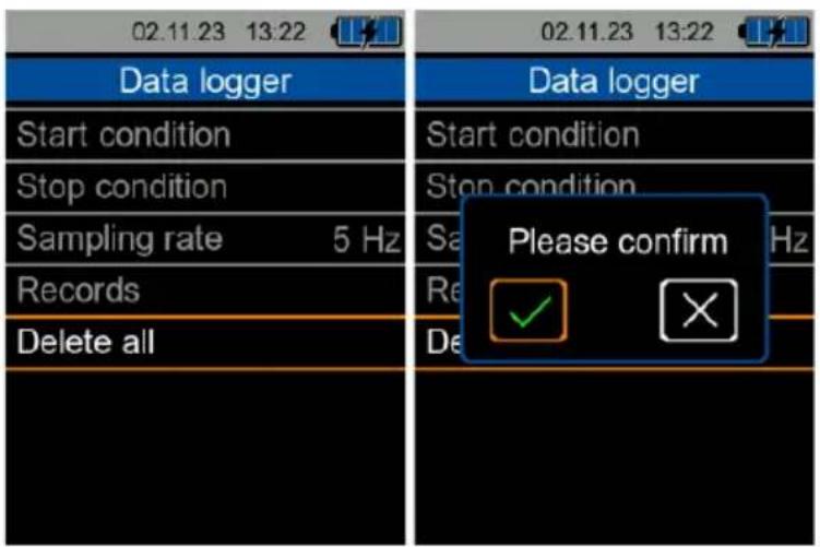
Use the ▲ or ▼ key to select the menu item Delete all and press the OK key to delete all measurement data. A dialogue window opens in which the deletion can be confirmed again with the tick or cancelled with the cross. Select the tick or the cross with the ◀/▶ keys and confirm the selection with the OK key.
5.2.3.6 Data logger dialogue
The data logger dialogue can be opened in any measuring screen by pressing and holding the OK key (3 seconds) and shows the current settings and the status of the data logger. When the dialogue is open, a recording can be started or stopped at any time by pressing and holding OK. In addition, the data logger menu opens when the dialogue is open and the MENU key is pressed.
5.2.4 Settings
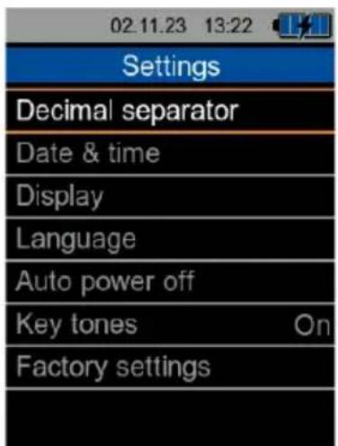
In the Settings menu, the general settings for the PCE-DFG X can be made. The Settings menu contains the following items for setting:
| Menu item | Description |
| Decimal separator | Switching the decimal separator between point and comma |
| Date & time | Setting the date and time as well as the time format |
| Display | Setting the display brightness and the display orientation |
| Language | Selecting the language |
| Auto power off | Setting the time for automatic power off |
| Key tones | Enabling or disabling the key tones |
| Factory settings | Resetting the meter to its factory settings |
In the main menu, use the ▲ or ▼ key to select the menu item Settings and press the OK key to enter the selected submenu. Press the back key to return to the main menu.
5.2.4.1 Decimal separator
Either a point or a comma can be selected as the decimal separator for measured values.
Use the ▲ or ▼ key to select the menu item Decimal separator and then press the OK key to make the setting for the decimal separator. The currently selected decimal separator is displayed with a tick next to it. Use the ▲ or ▼ key to select the desired decimal separator and then press the OK key to save the decimal separator setting. Press the back key to return to the previous menu item.
![02.11.23 13:22 Decimal separator Comma [.] Dot [.]](/content/2026/05/914743/images/8b7f8ba735290aebdecd92fd3d9ceda4a01ecefab28c38629325ed05da0b5381.jpg)

5.2.4.2 Date & time
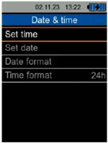
The date and time can be set in this menu. In addition, the date and time format can be selected. The following submenu items are included here:
| Menu item | Description |
| Set time | Dialogue sets the time |
| Set date | Dialogue sets the date |
| Date format | The date format can be selected in the submenu |
| Time format | Switches the time format between 12h and 24h |
Use the ▲ or ▼ key to select the Date & time menu item and then press the OK key to make the settings.
5.2.4.2.1 Set time
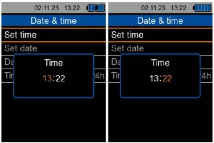
Use the ▲ or ▼ key to select the menu item Set time and press the OK key to change the time via the input dialogue. To change the time, use the ▶ key to select the digit to be changed. The digit to be changed is highlighted in orange. The ▲/▼ keys can now be used to change the hour within the range 00 ... 23 (depending on the time format) and the minute within the range 00 ... 59. To confirm the set value, press the OK key again.
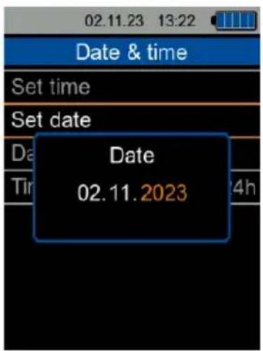
5.2.4.2.2 Set date
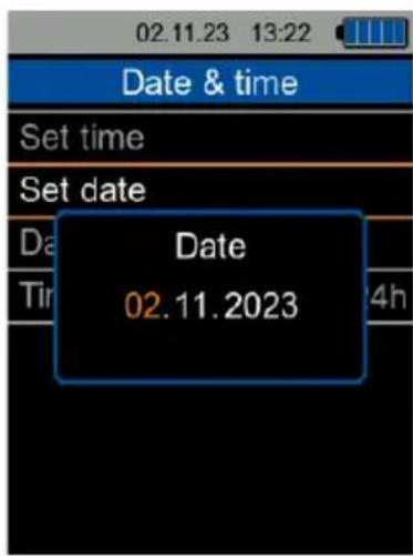
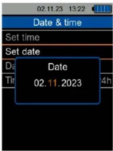
Use the ▲ or ▼ key to select the menu item Set date and press the OK key to change the date via the input dialogue. To change the date, use the ▶ key to select the digit to be changed. The digit to be changed is highlighted in orange. With the ▲/▼ keys, you can now select the day within the range 01 ... 31 (depending on the month), the month within the range 01 ... 12 and the year within the range 2023 ... 2060. To confirm the set value, press the OK key again.
5.2.4.2.3 Date format
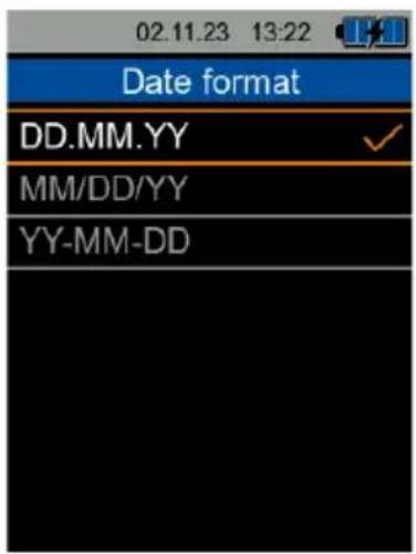
Use the ▲ or ▼ key to select the menu item Date format and press the OK key to adjust the date format in the next submenu. Now use the ▲/▼ keys to choose between DD.MM.YYYY, MM/DD/YYYY or YYYY-MM-DD and confirm the orange selection with the OK key. You can now return to the previous menu by pressing the back key.
5.2.4.2.4 Time format
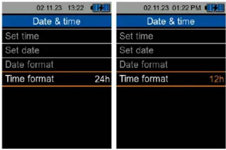
Use the ▲ or ▼ key to select the menu item Time format and press the OK key to adjust the time format in the next step. The currently set format is now highlighted in orange. Now use the ▲ or ▼ key to select between 12h and 24h and confirm the setting with the OK key. You can then return to the previous menu with the back key.
5.2.4.3 Display
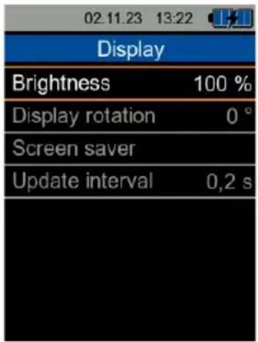
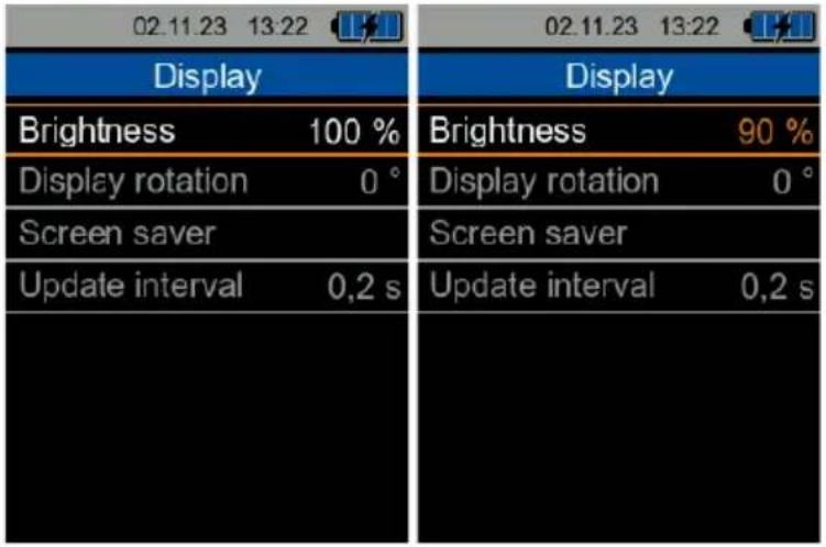
In this menu, the screen brightness can be adjusted between 50 and 100 %. In addition, an automatic dimming function can be set. After the set time, the display is dimmed to a lower brightness to save power. Pressing any key returns the brightness to the originally set value.
5.2.4.3.1 Brightness
Use the ▲ or ▼ key to select the Brightness menu item and press the OK key to change the brightness. The currently set brightness is now marked in orange. You can now use the ▲ or ▼ key to change the brightness within the range 50 ... 100 % in 10 % steps. Confirm the setting with the OK key.
5.2.4.3.2 Display rotation
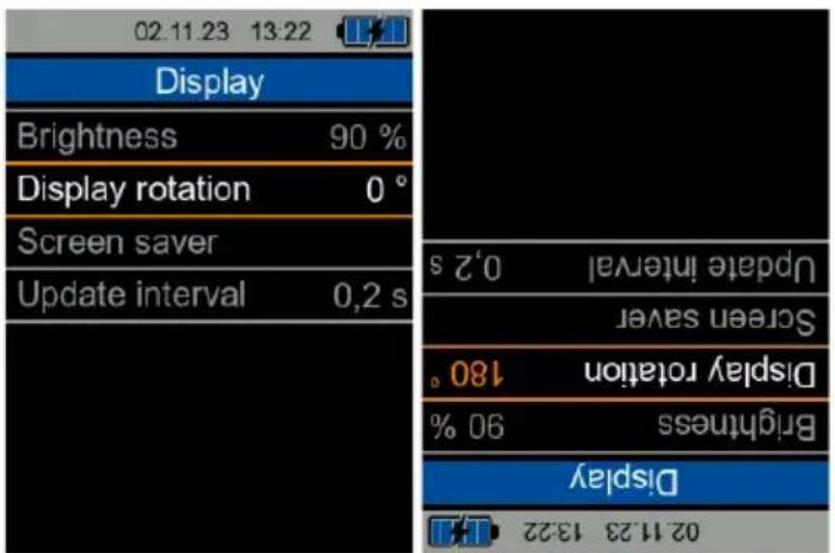
The display rotation parameter lets you rotate the screen from 0^ to 180^ and swap the key ▲ with the ▼ key and the key ▶ with the ◀ key. This is very useful when you need to place the device in a test bench.
Use the ▲ or ▼ key to select the menu item Display rotation and press the OK key to be able to select the desired rotation. Use ▲ and ▼ keys to select the rotation value and press the OK key to confirm it. The device screen will then rotate automatically. The options are 0° and 180°.
Note:
The ▲ and ▼ keys will also work in the opposite way when display rotation is at 180°.
5.2.4.3.3 Screen saver
The screen saver or the automatic dimming of the display serves to save battery power. The display automatically dims to the preset brightness value after the set time of inactivity.
Use the ▲ or ▼ key to select the menu item Screen saver and press the OK key to adjust the screen saver in the next submenu.
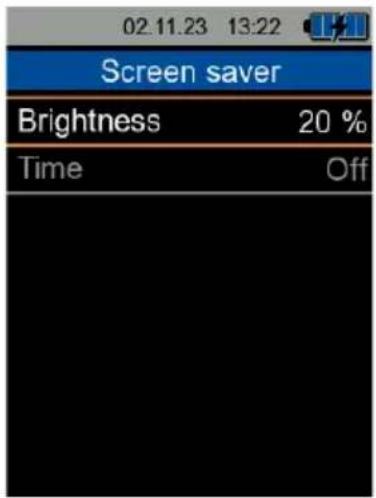
Use the ▲ or ▼ key to navigate to the Brightness menu item to set the display brightness to which the meter should automatically dim. Confirm the selection with the OK key. The currently set brightness is now highlighted in orange. You can now use the ▲ or ▼ key to change the brightness within the range 20 ... 60 % in 10 % steps. Confirm the setting with the OK key.

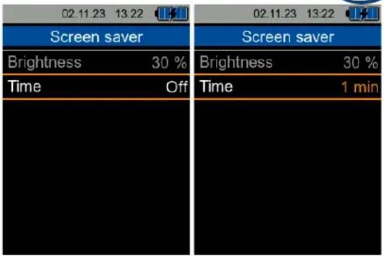
Use the ▲ or ▼ keys to navigate to the Time menu item to set how long it should take for the display to dim automatically. Confirm the selection with the OK key. The currently set time is now highlighted in orange. You can now use the ▲ or ▼ key to select between Off, 1 min, 3 min and 5 min. Confirm the setting with the OK key.
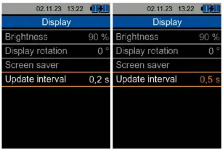
5.2.4.3.4 Update interval
Use the ▲ or ▼ key to select the Update interval menu item and press the OK key to change the update interval of the data in the measurement screen. The currently set update interval is now marked in orange. You can now use the ▲ or ▼ key to change the interval to one of the values 0.2 s, 0.5 s, 1.0 s or 2.0 s. Confirm the setting with the OK key.
5.2.4.4 Language
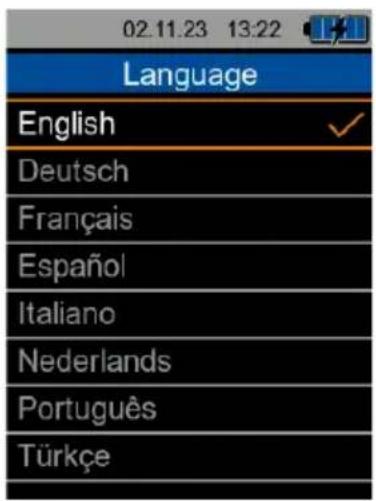
The available menu languages are English, German, French, Spanish, Italian, Dutch, Portuguese, Turkish, Polish, Russian, Chinese, Danish and Japanese.
In the settings menu, use the ▲ or ▼ key to navigate to the Language menu item to set the language in the following submenu. Select one of the listed languages with the ▲ or ▼ key and confirm the setting with the OK key. The meter switches directly to the selected language and a tick is displayed next to the selected language.
Note:
To reset an incorrectly set language, switch off the meter with the on/off key. Then switch on the meter while pressing and holding the back key. You will automatically be taken to the language settings and the meter will set to English as default.
5.2.4.5 Auto power off
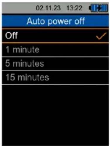
This option can be used to set an automatic power off time of the meter. The device switches off when the energy-saving mode is activated if no key has been pressed for a certain period of time. You can select between 1 minute, 5 minutes and 15 minutes. In addition, the automatic power off can be completely deactivated.
In the settings menu, use the ▲ or ▼ key to navigate to the Auto power off menu item in order to set the time until switch-off in the following submenu. Use the ▲ or ▼ key to select one of the listed options and confirm the setting with the OK key. A tick is displayed next to the selected setting.
5.2.4.6 Key tones
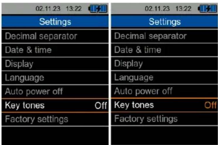
With this option, the sound of the keys when pressed is enabled or disabled. Use the ▲ or ▼ key to select the menu item Key tones and press the OK key. Now, the option to be set is highlighted in orange. Now use the ▲ or ▼ key to change the set value. Finally, press the OK key to save the setting.
5.2.4.7 Factory settings
With the help of this option, the device can be reset to the factory settings. When resetting the device settings, the default values for the measurement parameters and the remaining menu options are restored.
Use the ▲ or ▼ key to select the menu item Factory settings and press the OK key to reset the device. This setting is protected against access with the code 1402. This is entered in a pop-up dialogue. The entry always starts at the first digit.
To enter the code, use the ◀/▶ keys to select the digit to be adjusted. The digit to be changed is highlighted in orange. Use the ▲/▼ keys to change the selected digit within the range 0 ... 9. To confirm the entered code, press the OK key again. If the code was entered correctly, you will be taken to the submenu, otherwise an error message will appear.
A dialogue window now opens in which the reset can be confirmed again via the tick or cancelled via the cross. Select the tick or the cross with the ◀/▶ keys and confirm the selection with the OK key. A dialogue window appears which confirms the reset. Close this window with the OK key.
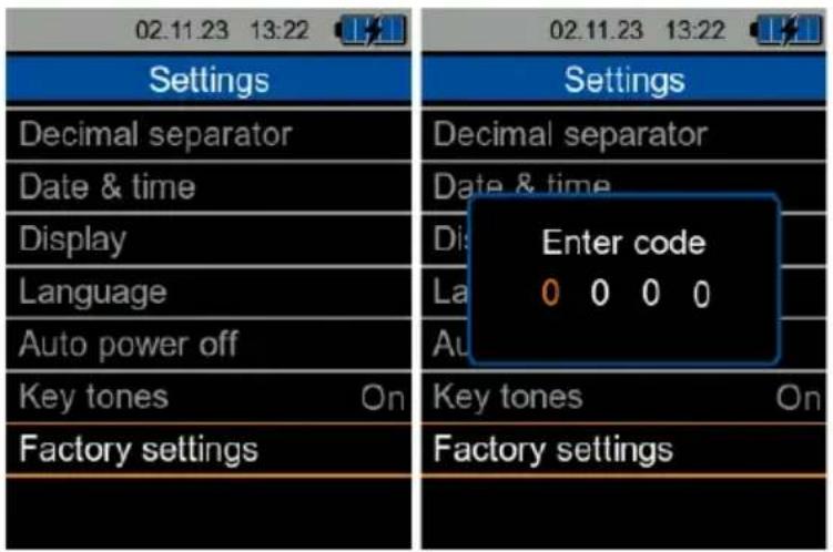
The factory settings are as follows:
| Setting | Factory setting |
| Unit | N or kN (depending on the force gauge maximum value) |
| Alarm | Overrun |
| Gravity value | 9.8115 |
| Threshold | ±0.01 |
| Measuring direction | Compression |
| Decimal separator | Comma [,] |
| Display brightness | 80 % |
| Screen saver brightness | 20 % |
| Update interval | 0.2 s |
| Time screensaver | Off |
| Language | English |
| Auto power off | Off |
| Start condition data logger | Manual |
| Stop condition data logger | Manual |
| Sampling rate | 5 Hz |
| High resolution | Disabled |
Note:
Calibration data is not lost!
5.2.5 Calibration
To open the Calibration menu, press the MENU key in the measurement screen, then use the ▲ or ▼ key to navigate to the Calibration menu item and confirm your selection with the OK key.
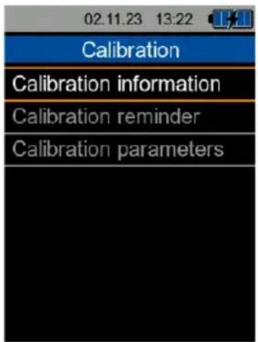
Note:
If your force gauge needs calibration or adjustment, please contact PCE Instruments. You will find the contact details at the end of this manual.
5.2.5.1 Calibration information
By selecting the menu item Calibration information, the date of the last calibration is shown. This menu item is purely an information display without any input options. The menu shows the last calibration date, the next calibration date, if the factory calibration has been carried out and the calibration number to give you some control over the calibrations.
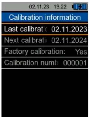
To view the calibration information, navigate to the Calibration information menu item using the ▲ or ▼ key and confirm the selection with the OK key.
5.2.5.2 Calibration reminder
In this menu, a reminder for a pending calibration can be set. The calibration reminder appears as a pop-up dialogue when the meter is switched on until the meter has been calibrated again by the PCE Instruments laboratory. To set the calibration reminder, navigate to the Calibration reminder menu item using the ▲ or ▼ key and confirm the selection with the OK key. A submenu now opens in which the settings are to be made as follows.
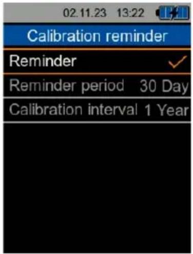

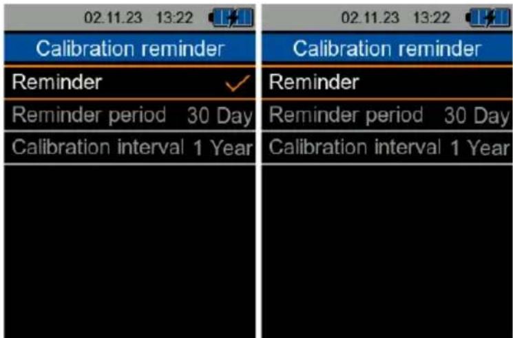
5.2.5.2.1 Reminder
To enable or disable the reminder, the tick next to the word "Reminder" can be set or removed using the OK key. Navigate to the Reminder item using the ▲ or ▼ key and activate or deactivate Reminder with the OK key.
5.2.5.2.2 Reminder period
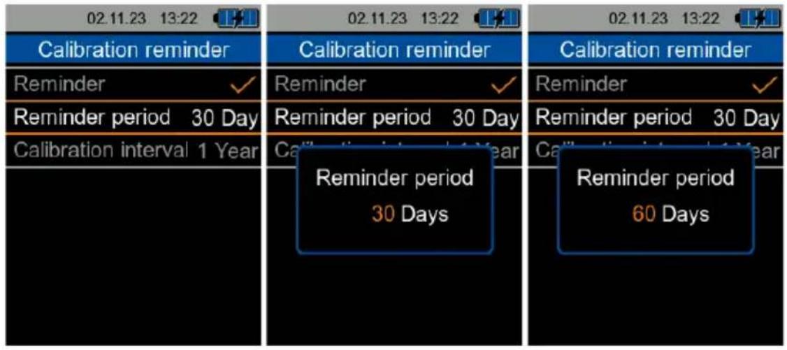
You can set the reminder to 30/60/90 days before the calibration expires. Use the ▲ or ▼ key to navigate to the menu item Reminder period and confirm the highlighted selection with the OK key. You can now use the ▲ or ▼ key to change the reminder period step by step. Confirm the selection with the OK key.
5.2.5.2.3 Calibration interval
This is the calibration interval on the basis of which the date of the next calibration is calculated in the calibration information. It can be set in this menu item and it is protected by a code for the PCE technicians to set it to the adequate time. The interval can be set from 1 to 10 years.
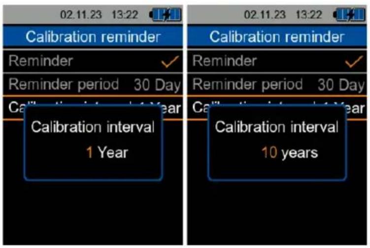
Use the ▲ or ▼ key to navigate to the Calibration interval menu item and confirm the highlighted selection with the OK key. You can now use the ▲ or ▼ key to change the interval by year. Confirm the selection with the OK key.
5.2.5.3 Calibration parameters
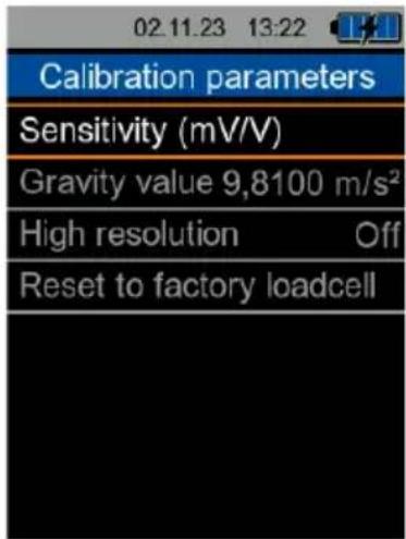
Here, all the parameters related to the calibration of the force gauge can be set. This menu is protected against access by the code 1703. This can be entered in a pop-up dialogue. The entry always starts at the first digit. To enter the code, use the ▶ key to select the digit to be adjusted. The digit to be changed is highlighted in orange. Use the ▲ or ▼ key to change the selected digit within the range 0 ... 9. To confirm the entered code, press the OK key again. If the code was entered correctly, you will enter the calibration menu, otherwise an error message will appear.
5.2.5.3.1 Sensitivity (mV/V)
Here, you can set the maximum load units, the maximum load value that the force gauge can support, the sensitivity of the gauge and the zero offset. In order to change any of these parameters, use the ▲ and ▼ keys to move to the desired item and press OK key to select it.
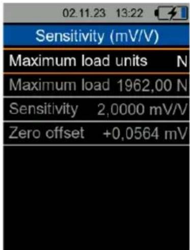
5.2.5.3.1.1 Maximum load unit
The maximum load unit determines the units for the maximum load value and the calibration weights of the calibration curves. The available options are kg, N and Nm. If a torque unit is selected, the units regarding weights or pressure will not be displayed in the Units submenu in the Measurement menu, and vice versa. Press OK to start selecting the unit and use ◀ and ▶ to choose between the options. Confirm the option with the OK key and use the back key to stop changing the option and restore the original.
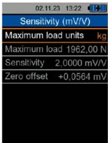
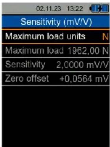
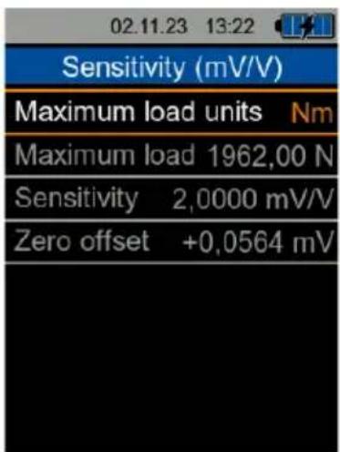
5.2.5.3.1.2 Maximum load
Depending on the maximum load unit selected, the maximum load value has to be entered in that unit. Once you have selected this item, a popup will appear. Here, you can select the digit to modify with the ◀ and ▶ keys and with the ▲ and ▼ keys, you can increase and reduce the value of the digit. Once the value is set, it can be saved by pressing the OK key. Press the back key to return to the sensitivity menu or discard the set value as long as the popup is visible.
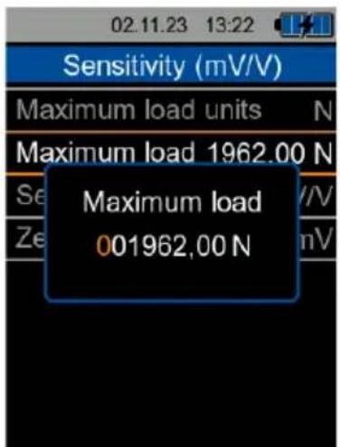
5.2.5.3.1.3 Sensitivity
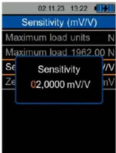
The sensitivity of the force gauge can be set here in mV/V. Once you have selected this item, a popup will appear. Here, you can select the digit to modify with the ◀ and ▶ keys and with the ▲ and ▼ keys, you can increase and reduce the value of the digit. Once the value is set, it can be saved by pressing the OK key. Press the back key to return to the Sensitivity menu or discard the set value as long as the popup is visible.
Attention:
Do not change this parameter when using the PCE-DFG X with internal load cell.
5.2.5.3.1.4 Zero offset
The zero offset of the force gauge can be set here. When the item is selected, a popup will appear and continuously display the reading of the force gauge in mV. In order to set the offset, the force gauge has to have no weight or force applied and once the value displayed has stabilized, press the OK key to store that value as zero offset.
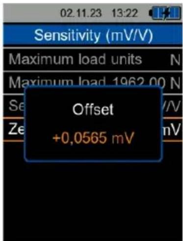
To return to the calibration menu, press the back key.
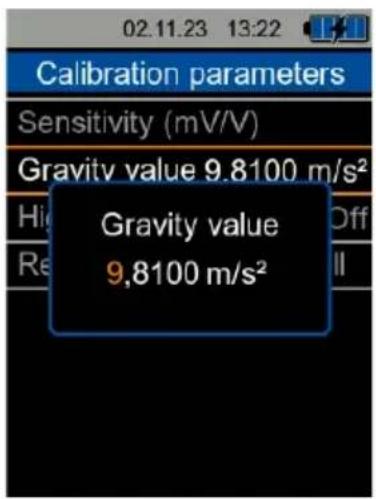
5.2.5.3.2 Gravity value
This parameter is used to adjust the measured values by the gravity value the user is experiencing and the gravity value used for the applied calibration. Once you have selected this item, a popup will appear. Here, you can select the digit to be modified with the ◀ and ▶ keys and with the ▲ and ▼ keys, you can increase and reduce the value of the digit. Once the value is set, it can be saved by pressing the OK key. Press the back key to return to the calibration menu or discard the set value as long as the popup is visible.
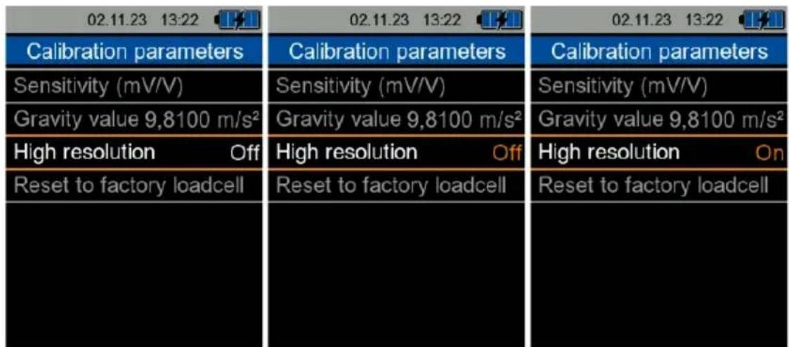
5.2.5.3.3 High resolution
This item allows you to select whether another decimal is to be displayed or not. This extra decimal will be more unstable than the others. Once this item is selected, you can use ▲ and ▼ to set it to On or Off. Once the item is set, press OK to save the selection.
5.2.5.3.4 Reset to factory load cell
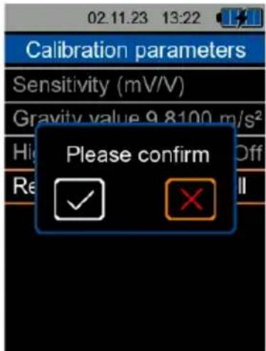
If you want to use a different load cell than the one that comes whit the device, the calibration for that should be configured by the calibration department of PCE Instruments. Once you want to go back to the original load cell, you can select this item to restore its calibration without the need of sending the device back to the calibration department. Once the item is selected, a popup asking for confirmation will appear.

5.2.6 Manual
A QR code is displayed in this menu. The QR code can be scanned with an appropriate reader such as a mobile phone and leads directly to these operating instructions.
When you are in the main menu, use the ▲ or ▼ key to navigate to the Manual item. If you now press the OK key, a QR code is shown on the display. Scan this code with your smartphone and your smartphone browser will open the detailed operating instructions as a PDF. Press the back key to return to the main menu.

5.2.7 Info
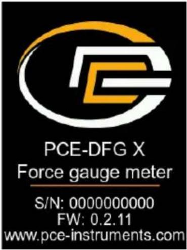
The Info menu displays the PCE Instruments logo, model number and name, serial number, firmware version and website.
In the main menu, use the ▲ or ▼ key to navigate to the Info menu item and then press the OK key. The device-specific information is now displayed. Press the back key to return to the main menu.
5.3 Software
The operation of the PC software is explained in a separate operating manual for the software. This can be downloaded from the PC software.
6 Contact
If you have any questions, suggestions or technical problems, please do not hesitate to contact us. You will find the relevant contact information at the end of this user manual.
7 Disposal
For the disposal of batteries in the EU, the 2006/66/EC directive of the European Parliament applies. Due to the contained pollutants, batteries must not be disposed of as household waste. They must be given to collection points designed for that purpose.
In order to comply with the EU directive 2012/19/EU we take our devices back. We either re-use them or give them to a recycling company which disposes of the devices in line with law.
For countries outside the EU, batteries and devices should be disposed of in accordance with your local waste regulations.
If you have any questions, please contact PCE Instruments.


PCE Instruments contact information
Germany France Spain
PCE Deutschland GmbH PCE Instruments France EURL PCE Ibérica S.L.
Im Langel 26 23, rue de Strasbourg Calle Mula, 8
D-59872 Meschede 67250 Soultz-Sous-Forets 02500 Tobarra (Albacete)
Chester Rd, Old Trafford
Manchester M32 0RS
United Kingdom
Tel: +44 (0) 161 464902 0
Fax: +44 (0) 161 464902 9
info@pce-instruments.co.uk
www.pce-instruments.com/english
Italy
PCE Italia s.r.l.
Via Pesciatina 878 / B-Interno 6
55010 Loc. Gragnano Pehlivan Sok. No.6/C
Capannori (Lucca)
Italia
www.pce-instruments.com/turkish
The Netherlands
PCE Brookhuis B.V.
Institutenweg 15
7521 PH Enschede
Nederland
Telefoon: +31 (0)53 737 01 92
info@pcebenelux.nl
www.pce-instruments.com/dutch Fax: +1 (561) 320-9176
info@pce-americas.com
www.pce-instruments.com/us
United States of America
PCE Americas Inc.
1201 Jupiter Park Drive, Suite 8
Jupiter / Palm Beach
33458 FL
USA
Tel: +1 (561) 320-9162
Denmark
PCE Instruments Denmark ApS
Birk Centerpark 40
7400 Herning
Denmark
Specifications are subject to change without notice.
- Schieber
- Software
- Specifications
- Force gauge with internal load cell
- Technical specifications
- Force gauge with external load cell
- Technical specifications
- Delivery scope
- Variant with internal cell:
- Variant with external cell:
- Accessories
- System description
- Device
- Model with external load cell
- Model with internal load cell
- Keypad
- Display
- Display modes
- Numerical display
- Statistical display
- Graphical display
- Slider
- Alarm
- Top bar
- Date / time
- Battery status
- Charging indicator
- PC connection
- Data logger
- Preparation
- Power supply
- Start-up
- Switch on
- Switch off
- Sensor connection (for force gauges with external measuring cell)
- Sensor disconnection
- Operation
- Measurements
- Main menu
- Main menu
- Measurement
- Unit
- Surface
- Alert
- Select alert mode
- Set alert limits
- Alert sound
- Gravity value
- Zero's threshold
- Measuring direction
- Data logger
- Start condition
- Starting the data logger manually
- Start by date and time
- Note:
- Starting the data logger when the limit value is exceeded
- Stop condition
- Stopping the data logger manually
- Stop by date and time
- Stopping the data logger when the value falls below the limit value
- Duration
- Sampling rate
- Records
- Delete all
- Data logger dialogue
- Settings
- Decimal separator
- Date & time
- Set time
- Set date
- Date format
- Time format
- Display
- Brightness
- Display rotation
- Screen saver
- Update interval
- Language
- Auto power off
- Key tones
- Factory settings
- Calibration
- Calibration information
- Calibration reminder
- Reminder
- Reminder period
- Calibration interval
- Calibration parameters
- Sensitivity (mV/V)
- Maximum load unit
- Maximum load
- Sensitivity
- Attention:
- Zero offset
- Gravity value
- High resolution
- Reset to factory load cell
- Manual
- Info
- Contact
- Disposal
- PCE Instruments contact information
- Germany France Spain
- Italy
- The Netherlands
- United States of America
- Denmark
Brand : PCE Instruments
Model : DFG 20K X
Category : Measurement