
CAS 60 - TV Antenna KATHREIN - Free user manual and instructions
Find the device manual for free CAS 60 KATHREIN in PDF.


| Product Type | Offset parabolic satellite antenna (domestic use) |
| Model | CAS 60 (order no. 20010006) |
| Reflector Material | Aluminum, powder coated |
| Feed Support Material | Galvanized sheet steel, plastic coated |
| Mast Clamp Material | Sheet steel, hot-dip galvanized |
| Available Colors | White (RAL 9002) or Graphite (RAL 7012) |
| Reflector Diameter | 57 cm |
| Dimensions (W x H x D) | 599 x 759 x 528 mm (without feed system) |
| Net Weight | 4.8 kg |
| Gross Weight (packed) | 5.6 kg |
| Packing Dimensions | 800 x 655 x 200 mm |
| Reception Frequency Range | 10.70 – 12.75 GHz |
| Antenna Gain (mid-band) | 34.9 – 35.9 dBi (depending on frequency) |
| Half-Power Beamwidth | < 2.8° |
| Cross-Polarisation Decoupling | > 27 dB |
| Wind Load | 300 N (at 800 N/m² dynamic pressure) |
| Max. Allowable Wind Speed | 157 km/h |
| Mast Clamp Range | 38 – 60 mm |
| Elevation Adjustment Range | 5° – 45° |
| Azimuth Adjustment Range | 360° |
| Figure of Merit (G/T) – Single Feed | 14.7/15.7 dB/K (UAS 571/572/584/585) or 14.0/15.0 dB/K (UAS 481) |
| Multi-Feed Capability | Up to 2 feeds (6° or 9° spacing) or 3 with optional ZAS 90 adapter |
| Intended Use | Domestic satellite signal reception only |
| Safety Compliance | DIN EN 60728-11 (installation and grounding) |
| Warranty | 10 years corrosion resistance (conditions apply) |
| Included Accessories | Reflector, mast and feed support, hexagon key (size 5) |
| Maintenance | Clean with soft damp cloth; do not use solvents or abrasives |
| Spare Parts | Use only genuine Kathrein accessories (e.g., ZAS 90, feed systems) |
| Repairability | No user-serviceable parts; modifications void warranty |
Frequently Asked Questions - CAS 60 KATHREIN
User questions about CAS 60 KATHREIN
0 question about this device. Answer the ones you know or ask your own.
Ask a new question about this device
Download the instructions for your TV Antenna in PDF format for free! Find your manual CAS 60 - KATHREIN and take your electronic device back in hand. On this page are published all the documents necessary for the use of your device. CAS 60 by KATHREIN.
USER MANUAL CAS 60 KATHREIN
natural_image
Close-up of a SatAn satellite dish mounted on a stand, showing its logo and metallic components (no readable text beyond branding)c. Speisesystem (LNB)
natural_image
Diagram of two satellites with solar panels and a central antenna, no text or symbols present
natural_image
Diagram of two satellites receiving signals from a central tower, no text or symbols presentAntenne ausrichten
natural_image
Technical line drawing of a mechanical assembly with an inset showing a close-up of a component detail (no text or symbols present)natural_image
Illustration of a hand fastening a mechanical component with a curved arrow indicating motion (no text or symbols)
■ Reflector made of aluminium, powder coated
■ Feed system support made of galvanised sheet steel, plastic coated
■ Mast clamp made of sheet steel, hot-dip galvanised
■ Optimal electrical data combined with very compact mechanical dimensions due to offset feed
■ Available in graphite or white
■ Items supplied: Reflector, mast and feed system support, hexagon key (size 5)
■ Without additional components, two universal feed systems to receive signals of satellites 6° (e.g. ASTRA/EUTELSAT-HOTBIRD) or 9° apart can be mounted on the boom

natural_image
Satellite dish mounted on a stand, showing brand logo and text (no readable document text beyond branding)Intended Use
The CAS 06/CAS 60 parabolic antenna is intended solely for the reception of satellite signals and for use only as a domestic antenna.
DIN 4131 specifies that a domestic antenna should have no more than 6 m free mast length and a fixed-end moment up to 1650 Nm.
It is unsuitable for mounting on structures that are liable to vibration.
Make absolutely sure that the values for the maximum load listed in the Technical Data (on the last page) are complied with. If this load is exceeded, parts could break away!
The CAS 06/CAS 60 parabolic antenna is designed for use with a feed system (LNB) for reception of the signals from one satellite position, or two feed systems for multi-feed applications for reception of the signals from two satellite positions 6° or 9° apart.
If the additional ZAS 90 multi-feed adapter plate accessory is used, the parabolic antenna is also suitable for three feed systems. The feed systems and instructions for their installation are not included in the scope of supply of the parabolic antenna.

Do not use the parabolic antenna for purposes other than those listed in this manual! Any use other than that specified above will invalidate the warranty or guarantee.
In particular, never
• modify any of its components or
- fit any components other than those expressly intended by the manufacturer for use with the antenna.
Breach of these rules may lead to the antenna no longer being sufficiently stable and safe!
Basic Safety Instructions
Before you install, connect or use the parabolic antenna, make sure that you comply with the instructions in this manual! If you disregard these instructions,
- malfunctions may arise, creating risks to your life and health,
- defects in the installation or the connection may cause damage to the antenna or to the attachment point,
- the manufacturer will not accept liability for malfunctions and damage arising!

- Under no circumstances install antennas in the vicinity of overhead power cables, otherwise the required clearances, which are absolutely essential, may no longer be satisfied. Maintain a clearance of at least 1 m from all other electrical equipment in all directions! If you or metal parts of the antenna touch any electrical device there is a serious risk of a fatal electric shock!
- Never work on antenna systems during a thunderstorm or when a thunderstorm is approaching. There is a risk of a fatal electric shock!
- Never install antennas on buildings with easily flammable roof coverings such as straw, rushes or similar materials! Otherwise there is a risk of fire due to atmospheric over-voltages (static charges) or lightning discharges (e.g. during thunderstorms).
- The installation operations described here assume good craftsmanship capabilities and knowledge of the behaviour of materials under the effects of wind. Therefore if you do not possess the required skills, have this work performed by a specialist.
- The person doing the work must wear strong non-slip footwear, must not be liable to dizziness, must be able to move around safely on the roof and have a secure standing and attachment position (if necessary, wear a safety harness when on the roof).
- Make sure that the roof is able to bear your weight. Never walk on fragile or unstable surfaces! In case of doubt, contact a qualified specialist dealer or specialist roofing contractor to find an appropriate installation location.
- Do not go on to roofs or other high places without a correctly attached safety harness that is in good condition. Otherwise use a work platform.
- Ladders or other means of climbing must be in faultless condition (dry, clean and non-slip). Never build any irresponsible “scrambling towers”!
- If there is a risk that passers-by may be injured by items falling from above during installation, you must close off the risk area using barriers! Make sure that no-one is underneath the installation location. Risk of death or injury due to falling from the roof, falling through the roof and falling parts, plus the possibility of damage to the roof.
- The respective national safety regulations and current standards such as DIN EN 60728-11 should be complied with.
- Any other use or failure to comply with these instructions will result in voiding of warranty coverage.

When working on antenna systems, please remember your duty of care towards your fellow human beings!
Keep the manual for any questions that arise later, and if the building passes to another owner, pass it on to the new owner!
Selecting the Installation Site
It is essential to select the correct installation site. This determines whether your parabolic antenna can be erected safely and perform to its optimum capabilities.
When selecting the installation site, take account of special features of the structure of the building. If the installation is at the edge of the roof or the building or on a cylindrical structure, DIN 1055, parts 4 and 4131 specifies the increased wind and vibration loadings that should be allowed for. The dynamic properties of the antenna and the structure can mutually influence each other and cause detrimental changes.
Disregarding these considerations can lead to the maximum load or vibration fatigue stress listed in the Technical Data being exceeded. The parabolic antenna need not necessarily be mounted on the roof, since the requirement is not height as such but an unobstructed “view” of the satellite. For this reason, an appropriate installation site might also be found for instance in the garden, on the terrace, on the face of the building or on a garage.
In fact if other sites are possible it is better to avoid the roof. This will result in less work for you and will reduce the hazards associated with installation work on the roof!
- For good reception, an unobstructed "view" to the south (± 20irc) must be ensured, at an elevation of about 30irc . The following satellites are then available for selection:
1 TÜRKSAT 42° East
6 EUTELSAT HOTBIRD
13irc East
2 ASTRA 2 group 28.2° East
3 ASTRA 3 group 23.5° East
7 EUTELSAT W 1 10° East
4 ASTRA 1 group 19.2° East
8 HISPA-Sat 30° West
5 EUTELSAT W 2 16° East
- Do make sure that there are no obstacles between the parabolic antenna and the respective satellite (such as trees, roofs, house eaves or other antennas). Such items can impair reception to the extent that during unfavourable stormy weather the signal is lost altogether.

Installing the Antenna
When installing the antenna carrier (mast or wall boom), ensure that it is standing upright. Otherwise, there may be problems with the alignment of the antenna to the satellites.
a. Requirements on the antenna carrier
Use only masts or support tubes that are specially designed for installation of antennas. Other tubes generally do not have the strength required to withstand the forces of wind and weather.
- For mast installation, select a tube diameter between 48 and 90 mm , with a wall thickness at least 2mm . For wall installation, Kathrein recommends the use of ZAS 60 or ZAS 61 wall brackets.
- For mast installation on a roof, the mast must be clamped for at least 1/6 of its free length (in the example bottom right this is 0.7m ).
b. Several antennas on a single antenna carrier:
- Install the parabolic antenna as far down the mast as possible, so as to minimise the bending moment at the clamping point.
- Under no circumstances exceed the maximum value for the loading on the mast or mast support, as stated in the Technical Data. Sufficient cognizance of the maximum loading is achieved if you arrange your antenna system as shown in example bottom right and use conventional domestic antennas together with mast components from a specialist supplier (tube in steel grade St 52 with outer diameter 60 mm and wall thickness 2.5mm at the mast clamping point - e.g. ZSH 59 from Kathrein).


If you arrange the structure differently you must calculate wind loading and bending moment at the clamping point as specified in DIN EN 60728-11 (or have a specialist do the calculation for you).
c. Assembly of the boom and parabolic antenna
- Fit the reflector to the preassembled rear part on the antenna boom. Alternately tighten the wing nuts on the mast clip finger-tight (①).
- Plug in the feed system boom and tighten the securing bolts (②). Use a hexagon key to tighten both the bolts on the boom to 4 - 5 Nm, see the two inset drawings in the illustration on the right.

d. Feed system (LNB)
The feed system(s) and instructions for their installation are not included in the scope of supply of the parabolic antenna.
For more detailed information on their correct installation please refer to the manuals supplied with the respective feed system.
- Using the multi-feed adapter plate on the carrier arm you can install one or two Kathrein universal feed systems. The markings on the adapter plate are as follows:
-
3 the installation position for one single feed system,
-
2 and 4 the installation positions for two multi-feed feed systems at 6° satellite spacing,
- 1 and 5 the installation positions for two multi-feed feed systems at 9irc satellite spacing.

See example on the next page
- Example for the installation positions for a multi-feed application with 6° satellite spacing:
Item 2 Item 4
ASTRA 19.2° East EUTELSAT 13° East
EUTELSAT 16° East EUTELSAT 10° East
EUTELSAT 13° East EUTELSAT 7° East
Tip
For multi-feed applications the antenna should be aligned towards the satellite which is transmitting the weakest signal level.
- Example for the installation positions for a multi-feed application with 9° satellite spacing:
Item 1 Item 5
ASTRA 19.2° East EUTELSAT 10° East
EUTELSAT 16° East EUTELSAT 7° East
Tip
For multi-feed applications the antenna should be aligned towards the satellite which is transmitting the weakest signal level.

natural_image
Diagram of two satellites with dish antennas and a central sensor array, no text or symbols present
natural_image
Diagram of two satellites receiving signals from a ground station (no text or labels)Aligning the Antenna
The antenna must be exactly aligned towards the satellite in respect of both the direction (azimuth) and also the inclination (elevation). For multi-feed applications the antenna should be aligned towards the satellite which is transmitting the weakest signal.
a. Adjusting the inclination (elevation)
- Use the hexagon key supplied with the parabolic antenna (①) to slacken the two screws on each side of the inclination scale (elevation) on the left and right of the clamp.
- Then adjust the inclination (elevation) – the exact elevation angle for your location can be found in the manual for the feed system (LNB).
- When doing this, retighten first just one of the bolts on the inclination scale finger-tight.

natural_image
Technical line drawing of a mechanical assembly with an inset showing a close-up of a component (no text or symbols present)b. Setting the direction (azimuth)
If you yourself are unable whilst performing the adjustments to read the results of the alignment work on an antenna meter or screen connected to the satellite receiver, you may need an assistant for the following steps. The precise alignment of the antenna can be achieved only if a digital antenna meter is used. Ask your dealer about this.
- Set the satellite receiver to a known channel so that you can check that you have really "locked on" to the desired satellite.
- Now slightly loosen the wing nuts on the mast clamp.
- Twist the antenna so that it faces roughly south. Then slowly twist the antenna about its central axis to left and right until the best reception is obtained for the selected channel.
- Then tighten the wing nuts initially just enough to prevent the antenna turning.
c. Fine adjustment
- Once again slacken the bolt on the inclination scale and tilt the antenna lightly upwards and downwards until either the antenna meter shows the strongest antenna signal or visual assessment is judged to achieve the best picture: To do this, tilt the antenna far enough upwards and downwards to get to the limits when the first "little fish" (analogue) or "little blocks" (digital) appear on the screen. Position the antenna midway between the two limit points.
- Now alternately correct the direction (azimuth) and inclination (elevation) until the measured results or the picture quality show no further improvement.
Note: Tightening the nuts at the clamping piece can cause the antenna to turn slightly! You should allow for this at the fine adjustment stage (and if necessary make use of it when starting the adjustment operation all over again).
d. Finally tightening the antenna clamps
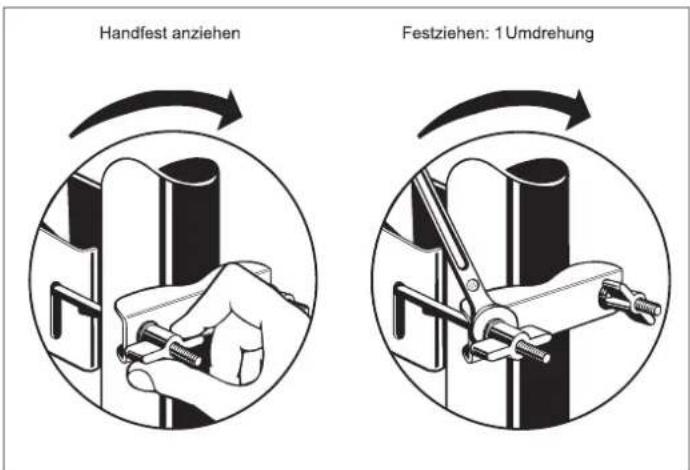
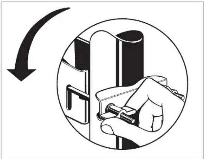
- Then tighten the nuts at the clamping piece by hand, working across diagonals. Then use a 13 AF open-ended spanner to tighten up each of the wing nuts one turn.
- After this, tighten the bolts on the left and right of the clamp of the inclination scale, using the hexagon key first with the short end to tighten them finger-tight and then with the long end tighten them a further 1/4 - 1/2 turn (torque wrench: 4 - 5Nm ).
- Finally check once again that the bolted connections are secure.
- Attach the cables to the carrier arm by clipping them into the cable clips within the carrier arm and use cable ties to secure them all along the antenna carrier, so that they cannot chafe and suffer damage in the wind.
natural_image
Illustration of a hand using a tool to adjust or install a mechanical component, enclosed in a circular arrow (no text or symbols)

Antenna Grounding/Lightning Protection
Because of the serious consequences if the work is not done properly, grounding and lightning protection work may be performed only by specially trained electricians!

Never perform grounding and lightning protection work if you are not a specialist with the appropriate skills!
The instructions printed here are not an invitation to non-specialists to perform grounding and lightning protection work on their own account; they are meant solely as additional information for the specialists whom you employ!
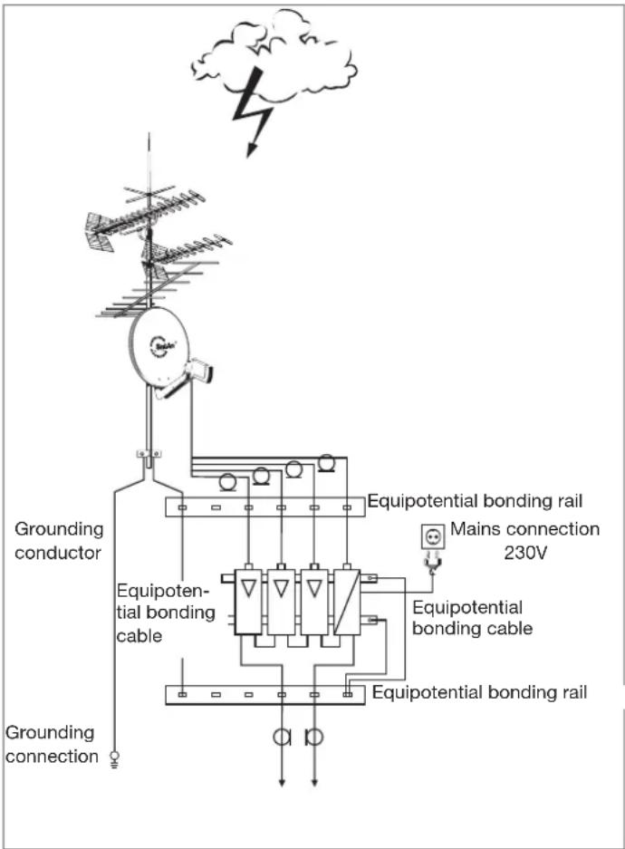
The antenna must be erected to DIN EN 60728-11 and grounded as specified. The grounding requirement is inapplicable only to those antennas:
- more than 2 m below the edge of the roof
• and at the same time less than 1.5 m from buildings.
For grounding, the mast must be connected by means of a suitable ground conductor to the lightning protection system of the building, using the shortest route. If no lightning protection system is available: to the building's ground conductor.
Connection to the lightning protection system may be made only by a qualified lightning protection system installation engineer.
a. Suitable as ground conductors are
- a single solid wire with a cross-section of at least 16mm2 copper, at least 25mm2 aluminium or at least 50mm2 steel.
b. Unsuitable as ground conductors are
– the outer conductor of the antenna cable
- metallic domestic installations (such as the metal pipework of a water or heating system), since the permanence of the electrical connection cannot be guaranteed
- or the shielding conductor or neutral conductor of the mains power supply.
c. Routing of ground conductors
- Antenna cables and grounding conductors must not be routed through rooms used for storing easily flammable substances (such as hay or straw) or in which an explosive atmosphere can develop (such as gases, vapours).
- If the parabolic antenna is used in an integrated antenna system (e.g. a distribution system), the grounding measures must also be designed in such a way that grounding protection is still maintained if individual units are removed or replaced.
flowchart
graph TD
    A["Grounding conductor"] --> B["Equipotential bonding cable"]
    B --> C["Equipotential bonding rail"]
    C --> D["Mains connection 230V"]
    D --> E["Grounding connection"]
    F["Wind Turbine"] --> G["Cloud with Down Arrow"]
    style A fill:#f9f,stroke:#333
    style B fill:#ccf,stroke:#333
    style C fill:#cfc,stroke:#333
    style D fill:#fcc,stroke:#333
    style E fill:#ffc,stroke:#333
    style F fill:#cff,stroke:#333

Hazards may be caused not only by thunderstorms (lightning), but also by static charges and short circuits in the connected units.
For safety reasons therefore in general for all antenna systems an equipotential bonding conductor of 4 mm2 copper should be provided.
The cable screens of all coaxial antenna downlink cables must be connected to the mast with an equipotential bonding conductor.
Technical Data
| Type CAS 06 CAS 60 | ||||
| Order no. | 20010005 20010006 | |||
| Diameter cm | 57 57 | |||
| Colour | White (similar to RAL 9002) | Graphite (similar to RAL 7012) | ||
| Reception range GHz | 10.70 – 12.75 | |||
| Antenna gain at 10.70 – 11.70 GHz/11.70 – 12.50 GHz/12.50 – 12.75 GHz dBi | 34.9/35.5/35.9 | |||
| Half-power beam width 1 | ° | < 2.8 | ||
| Figure of merit 2 Central feed system | UAS 571/572/584/585UAS 481 | dB/K | 14.7/15.714.0/15.0 | |
| Figure of merit 2 Feed system spacing 6 irc | UAS 571/572/584/585UAS 481 | dB/K | 14.3/15.313.6/14.3 | |
| Figure of merit 2 Feed system spacing 9 irc | UAS 571/572/584/585UAS 481 | dB/K | 13.6/14.412.9/13.7 | |
| Cross-polarisation decoupling dB | >27 | |||
| Wind load 3 | N | 300 | ||
| Max. allowable wind speed km/h | 157 | |||
| Mast clamp range mm | 38 – 60 | |||
| Setting range Elevation/Azimuth ° | 5 – 45/360 | |||
| Dimensions(width x height max. x protrusion max. from mast centre without feed system) | mm | 599 x 759 x 528 | ||
| Packing unit dimensions mm | 800 x 655 x 200 | |||
| Weight approx. net/gross kg | 4.8/5.6 | |||
1) At mid-band
2) G/T at 11.3/12.5 GHz under standard ambient conditions (clear sky)
3) At a dynamic pressure of 800 N/m² to EN 60728-11

All figures are typical values!
If the maximum load is exceeded, parts could break away!
Warranty Conditions for the Antenna Corrosion Resistance
Important instructions relating to the warranty conditions for the corrosion resistance of Kathrein offset parabolic antennas:
- The antenna must be assembled and mounted professionally, following the steps described in the enclosed instruction sheet.
• The antenna must not be modified (e.g. by drilling). - The antenna must not be damaged mechanically (e.g. deformation, deep or extensive damage, or abrasion of the powder coating and surface coating).
- The antenna must not be damaged due to exposure to chemicals (e.g. solvents, lacquers, detergents or the like).
- Only genuine Kathrein accessories may be used for the antenna.

These warranty conditions are effective from the date of purchase.
Only the original sales slip is acceptable as proof of purchase for warranty claims.
Furthermore, corrosion resistance is not warranted for the consequences of force majeure, e.g. lightning strike, or if the antenna is used in regions where frequently occurring, abrasive weather conditions may wear off the protective coating within a short period of time (e.g. sandstorms).
Waste Disposal
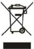
Electronic equipment is not household waste in accordance with directive 2002/96/EC OF THE EUROPEAN PARLIAMENT AND THE COUNCIL dated 27 th January 2003 on used electrical and electronic equipment, it must be disposed of properly.
At the end of its service life, take this unit for disposal to an appropriate official collection point.



- c. Speisesystem (LNB)
- Antenne ausrichten
- Intended Use
- Basic Safety Instructions
- Selecting the Installation Site
- Installing the Antenna
- a. Requirements on the antenna carrier
- b. Several antennas on a single antenna carrier:
- c. Assembly of the boom and parabolic antenna
- d. Feed system (LNB)
- Item 2 Item 4
- Tip
- Item 1 Item 5
- Aligning the Antenna
- a. Adjusting the inclination (elevation)
- b. Setting the direction (azimuth)
- c. Fine adjustment
- d. Finally tightening the antenna clamps
- Antenna Grounding/Lightning Protection
- a. Suitable as ground conductors are
- b. Unsuitable as ground conductors are
- c. Routing of ground conductors
- Warranty Conditions for the Antenna Corrosion Resistance
- Waste Disposal
Brand : KATHREIN
Model : CAS 60
Category : TV Antenna